JP3810285B2 - Half-mating prevention connector - Google Patents
Half-mating prevention connector Download PDFInfo
- Publication number
- JP3810285B2 JP3810285B2 JP2001177292A JP2001177292A JP3810285B2 JP 3810285 B2 JP3810285 B2 JP 3810285B2 JP 2001177292 A JP2001177292 A JP 2001177292A JP 2001177292 A JP2001177292 A JP 2001177292A JP 3810285 B2 JP3810285 B2 JP 3810285B2
- Authority
- JP
- Japan
- Prior art keywords
- fitting
- detection member
- connector
- connector housing
- protrusion
- Prior art date
- Legal status (The legal status is an assumption and is not a legal conclusion. Google has not performed a legal analysis and makes no representation as to the accuracy of the status listed.)
- Expired - Fee Related
Links
Images


Classifications
-
- H—ELECTRICITY
- H01—ELECTRIC ELEMENTS
- H01R—ELECTRICALLY-CONDUCTIVE CONNECTIONS; STRUCTURAL ASSOCIATIONS OF A PLURALITY OF MUTUALLY-INSULATED ELECTRICAL CONNECTING ELEMENTS; COUPLING DEVICES; CURRENT COLLECTORS
- H01R13/00—Details of coupling devices of the kinds covered by groups H01R12/70 or H01R24/00 - H01R33/00
- H01R13/62—Means for facilitating engagement or disengagement of coupling parts or for holding them in engagement
- H01R13/627—Snap or like fastening
- H01R13/6271—Latching means integral with the housing
- H01R13/6272—Latching means integral with the housing comprising a single latching arm
-
- H—ELECTRICITY
- H01—ELECTRIC ELEMENTS
- H01R—ELECTRICALLY-CONDUCTIVE CONNECTIONS; STRUCTURAL ASSOCIATIONS OF A PLURALITY OF MUTUALLY-INSULATED ELECTRICAL CONNECTING ELEMENTS; COUPLING DEVICES; CURRENT COLLECTORS
- H01R13/00—Details of coupling devices of the kinds covered by groups H01R12/70 or H01R24/00 - H01R33/00
- H01R13/62—Means for facilitating engagement or disengagement of coupling parts or for holding them in engagement
- H01R13/639—Additional means for holding or locking coupling parts together, after engagement, e.g. separate keylock, retainer strap
-
- H—ELECTRICITY
- H01—ELECTRIC ELEMENTS
- H01R—ELECTRICALLY-CONDUCTIVE CONNECTIONS; STRUCTURAL ASSOCIATIONS OF A PLURALITY OF MUTUALLY-INSULATED ELECTRICAL CONNECTING ELEMENTS; COUPLING DEVICES; CURRENT COLLECTORS
- H01R13/00—Details of coupling devices of the kinds covered by groups H01R12/70 or H01R24/00 - H01R33/00
- H01R13/64—Means for preventing incorrect coupling
- H01R13/641—Means for preventing incorrect coupling by indicating incorrect coupling; by indicating correct or full engagement
Landscapes
- Details Of Connecting Devices For Male And Female Coupling (AREA)
Description
【0001】
【発明の属する技術分野】
本発明は、一組の雌雄コネクタハウジング相互を嵌合させた際に、一方のコネクタハウジングに装着された嵌合検知部材の適正嵌合検知位置へのスライド移動の可否によって、雌雄コネクタハウジング相互の中途嵌合状態を検知する半嵌合防止コネクタに関するものである。
【0002】
【従来の技術】
従来の半嵌合防止コネクタは、図7及び図8に示したように雄コネクタハウジング1と雌コネクタハウジング9との一組の雌雄コネクタハウジング1,9相互を嵌合させた際に、一方の雄コネクタハウジング1に装着された嵌合検知部材2の適正嵌合検知位置へのスライド移動の可否によって、雌雄コネクタハウジング1,9相互の中途嵌合状態を検知するものである。(特開平8−31517号公報参照)
【0003】
図8に示したように雄コネクタハウジング1は、上壁3の前端側から立ち上がってハウジング後方に延びる可撓ロックアーム4を有しており、この可撓ロックアーム4の中間部上面にはロック部6が突設されている。
また、雄コネクタハウジング1の後端寄りに位置する可撓ロックアーム4の自由端には、雌雄コネクタハウジング相互の嵌合時に可撓ロックアーム4を可撓変位させる操作部である押圧板部7が設けられている。
【0004】
また、前記雌コネクタハウジング9は、雌雄コネクタハウジング1,9相互の嵌合の際に前記可撓ロックアーム4の上に被さる上壁の内面側前端に係合部10を有している。
図9及び図10に示したように、前記係合部10は、雌雄コネクタハウジング1,9相互の嵌合時の嵌合長が適正値に達する時に、前記可撓ロックアーム4の可撓変位を介して前記ロック部6を乗り越える。そして、雌雄コネクタハウジング1,9相互の嵌合長が適正値に達した時に、前記ロック部6の後方の凹部6aに上方から係合することでロック部6を係止して、雌雄コネクタハウジング相互の嵌合状態をロックする。
【0005】
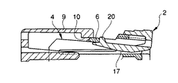
図7及び図8に示したように、前記嵌合検知部材2は、前記雌雄コネクタハウジング相互の嵌合方向に沿ってスライド可能に前記押圧板部7に係合する操作板部16と、この操作板部16の後端部から雌雄コネクタハウジングの前端側に向かって延出した弾性片17と、この弾性片17の先端に突設された位置決め係止部20とを一体形成したものである。なお、前記弾性片17は、前記可撓ロックアーム4を構成する一組の側板部5,5間の空間を挿通可能な棒状を呈している。
【0006】
また、図7に示すように、前記位置決め係止部20は、前記弾性片17による付勢力で前記ロック部6の前後の凹部6a,6bに下側から嵌入可能な突起で、雌雄コネクタハウジング相互の嵌合前は、ロック部6の後方の凹部6aに嵌合した状態で、ロック部6の後縁に係止されて前方への移動が規制される。
【0007】
前記位置決め係止部20がロック部6の後縁に当接して前方への変位が規制された位置が、雄コネクタハウジング1に装着された嵌合検知部材2の初期位置である。
また、前記押圧板部7と操作板部16との間のスライド可能な係合は、前記初期位置よりも前方に設定された適正嵌合検知位置と前記初期位置との間を嵌合検知部材2がスライド可能となるようにスライド可能な範囲が設定されている。
【0008】
図10に示したように、一組の雌雄コネクタハウジング1,9相互を嵌合させた際、雌雄コネクタハウジング1,9相互の嵌合長が適正値に達して、ロック部6の後方の凹部6aに雌コネクタハウジング9の係合部10が嵌入する。
これにより、前記凹部6aに嵌合していた嵌合検知部材2の位置決め係止部20が、係合部10によって下方に押し出されて、位置決め係止部20に対する初期位置への位置規制が解除される。その結果、嵌合検知部材2は、図中に矢印Aで示したように、操作板部16を前方に押すとスライド可能となる。
【0009】
図11に示したように、前記位置決め係止部20は、初期位置への位置規制が解除された状態で嵌合検知部材2を前方に移動操作すると、係合部10及びロック部6の下面を摺接して前方に進む。そして、前記位置決め係止部20は、前記ロック部6の前縁を越えたときに、弾性片17の付勢力で上方に変位してロック部6の前方の凹部6bに嵌入する。
これにより、前記凹部6bに嵌入した位置決め係止部20は、その後端面がロック部6の前端面によって係止され、後方へのスライド移動が規制されたロック状態となる。
【0010】
ところが、前記雌雄コネクタハウジング1,9相互を嵌合させた際に、前記雌雄コネクタハウジング1,9相互の嵌合長が適正値に到達せずに、中途嵌合状態の場合には、雌コネクタハウジング9の係合部10がロック部6の後方の凹部6aに嵌入しない。
そのため、前記位置決め係止部20が、前記係合部10によって凹部6aから押し出されることがなく、前記ロック部6による嵌合検知部材2の初期位置への位置規制が解除されない。
従って、雌雄コネクタハウジング相互の中途嵌合時には、嵌合検知部材2の操作板部16を前方に押しても、前記嵌合検知部材2が前方に移動することはなく、この嵌合検知部材2の前方への移動の可否によって中途嵌合状態を検知することができる。
【0011】
【発明が解決しようとする課題】
ところで、前記雌雄コネクタハウジング1,9相互を嵌合させた後、嵌合検知部材2の操作板部16が露出しているため、設定以上の外力が操作板部16の上方から作用すると、可撓ロックアーム4と雄コネクタハウジング1との間に撓みスペースが存在するため、可撓ロックアーム4が撓んで雌雄コネクタハウジング1,9相互のロックが解除されてしまうという問題があった。
【0012】
本発明は、上記課題に鑑みてなされたものであり、完全嵌合時におけるロックアームの撓みを防止し、安定した嵌合状態を保持するための半嵌合防止コネクタを提供することを目的とする。
【0013】
【課題を解決するための手段】
上記目的を達成するための本発明の請求項1に係る半嵌合防止コネクタは、可撓ロックアームを有する一方のコネクタハウジングと、
前記可撓ロックアームのロック部に係合する係合部を有して前記一方のコネクタハウジングに嵌合させた際に前記ロック部と前記係合部との係合によって前記一方のコネクタハウジングに連結される他方のコネクタハウジングと、
前記一方のコネクタハウジングに該コネクタハウジング相互の嵌合方向に沿ってスライド可能に装着され、スライド移動の可否によって前記コネクタハウジング相互の中途嵌合状態を検知する嵌合検知部材とを備えた半嵌合防止コネクタであって、
前記嵌合検知部材は、前記コネクタハウジング相互の嵌合方向に沿ってスライド可能に前記一方のコネクタハウジングの外周に嵌合する検知部材本体と、前記ロック部との係合によって前記検知部材本体を初期位置に規制する位置決め係止部と、後端に完全嵌合時に前記ロックアームの撓みを防止する撓み防止リブとを備え、
前記コネクタハウジング相互の完全嵌合時は、前記係合部の前記ロック部への係合に伴って前記位置決め係止部が前記ロック部から押し出されて前記ロック部との係合状態が解除され、前記検知部材本体が前記初期位置から前記一方のコネクタハウジングの前端寄りの適正嵌合検知位置にスライド移動することで、
前記位置決め係止部が前記ロックアーム先端の検知部材係止部に係合され、前記嵌合検知部材が前記適正嵌合検知位置に位置規制されると共に、
前記撓み防止リブが前記ロックアームの下方に入り込んで前記ロックアームの撓みを防止することを特徴とする。
【0014】
上記構成の半嵌合防止コネクタによれば、一方のコネクタハウジングに装着された嵌合検知部材の後端に完全嵌合時にロックアームの撓みを防止する撓み防止リブを備えており、完全嵌合時に撓み防止リブがロックアームの下方に入り込んで前記ロックアームの撓みを防止する。そのため、ロックアームに荷重が掛かってもロックが解除されてしまうことはなく、安定した嵌合状態を保持することができる。
なお、前記撓み防止リブは、ロックアームの可撓空間を埋めるものであればよく、嵌合検知部材の両側壁間に渡設される必要はない。すなわち、前記撓み防止リブは、嵌合検知部材の両側壁間で分離し、それぞれが片持ち梁となっていても良い。
【0015】
また、上記目的を達成するための本発明の請求項2に係る半嵌合防止コネクタは、請求項1記載の半嵌合防止コネクタであって、前記一方のコネクタハウジングが前記可撓ロックアームの反対側の外周に第1突部を有すると共に、前記コネクタハウジング相互の完全嵌合時に前記第1突部に係合する第2突部を前記嵌合検知部材の内周に有し、前記他方のコネクタハウジングとの完全嵌合に伴って前記嵌合検知部材が前記一方のコネクタハウジングの前方に移動することで、前記第2突部が前記第1突部を乗り越えて係合することを特徴とする。
【0016】
前記構成の半嵌合防止コネクタによれば、一方のコネクタハウジングが可撓ロックアームの反対側の外周に第1突部を有すると共に、コネクタハウジング相互の完全嵌合時に前記第1突部に係合する第2突部を嵌合検知部材の内周に有し、他方のコネクタハウジングとの完全嵌合に伴って前記嵌合検知部材が前記一方のコネクタハウジングの前方に移動することで、前記第2突部が前記第1突部を乗り越えて係合する。そのため、前記位置決め係止部と前記ロックアーム先端の検知部材係止部との係合に加え、前記第1突部と前記第2突部が係合することにより、完全嵌合時の前記嵌合検知部材と前記一方のコネクタハウジングの係止力が向上して、前記嵌合検知部材の前記適正嵌合検知位置への位置規制をさらに強固に保持することができる。また、前記第1突部と前記第2突部が係合するときにクリック感が発生し、コネクタハウジング相互の完全嵌合状態をこのクリック感によっても検知することができる。
【0017】
【発明の実施の形態】
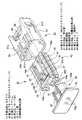
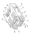
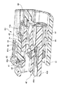
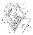
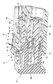
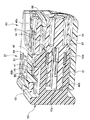
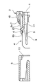
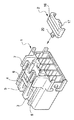
以下、本発明に係る半嵌合防止コネクタの好適な一実施形態を図1乃至図6に基づいて詳細に説明する。図1は本発明の半嵌合防止コネクタの一実施形態を示す分解斜視図、図2は図1における雌コネクタハウジングに嵌合検知部材を組み付けた状態を示す斜視図、図3は図2における縦断面図、図4は図1における雌雄コネクタハウジング相互の嵌合中の状態を示す斜視図、図5は図4における縦断面図、図6は図5における雌雄コネクタハウジング相互の完全嵌合状態を示す縦断面図である。
【0018】
図1に示すように本実施形態の半嵌合防止コネクタ31は、可撓ロックアーム41を有する一方のコネクタハウジングである雌コネクタ40と、前記可撓ロックアーム41上に設けられたロック部である係止孔42に係合する係合部である係合突起51を有する他方のコネクタハウジングである雄コネクタ50と、雌コネクタ40に嵌合方向に沿ってスライド可能に装着される略筒状の嵌合検知部材60とから構成されている。
図2乃至図3に示すように、前記嵌合検知部材60は、雌雄コネクタ40,50相互の嵌合前は前記係止孔42との係合によって初期位置に位置規制される。そして、図5乃至図6に示すように、雌雄コネクタ40,50相互の完全嵌合時には、前記係止孔42による位置規制が係合突起51の係止孔42への係合動作によって解除され、前記初期位置から所定距離離れた適正嵌合検知位置にスライド移動する。従って、この嵌合検知部材60の適正嵌合検知位置へのスライド移動の可否によって、雌雄コネクタ40,50相互の中途嵌合状態を検知することができる。
【0019】
本実施形態の雌コネクタ40は、図示していない雌形接続端子を収容保持する端子収容室40aが形成されたハウジング本体40bと、該ハウジング本体の上面に形成された前記可撓ロックアーム41と、嵌合検知部材60をスライド可能に支持するためのガイド部43とが一体成形された構造である。
【0020】
前記可撓ロックアーム41は、ハウジング本体40b上面の略中央に立設された支柱部44の上端に、ハウジング本体40bの前後方向に沿って延びるアーム部45を連設したもので、該アーム部45が支柱部44を支点に上下方向に可撓変位可能になっている。
【0021】
また、前記可撓ロックアーム41の係止孔42は、アーム部45の前端寄りの位置に設けられている。また、アーム部45の後端寄りの上面は、アーム部45の前端を上方に変位させるための解除操作部45aが設けられている。
従って、雌雄コネクタ40,50が嵌合して、雄コネクタ50の係合突起51が係止孔42に係合している状態で、解除操作部45aを押下してアーム部45の前端を上方に変位させると、係止孔42と係合突起51との係合状態を解除することができる。
【0022】
また、前記ガイド部43は、可撓ロックアーム41を挟むように、ハウジング本体40b上面の両側に形成されている。この各々ガイド部43は、外側面部にハウジング本体40bの前後方向に沿って延在するガイド溝43aを有している。
【0023】
また、図3に示すように、本実施形態の雌コネクタ40は、可撓ロックアーム41の反対側の外周に嵌合方向に対して直交する横方向に延設されたリブ状の第1突部48を有する。また、第1突部48の形状においては、緩やかな傾斜面を有する断面三角形状や半円形状が望ましい。
【0024】
また、本実施形態の雄コネクタ50は、雄形接続端子を収容する端子収容室50aが形成されたハウジング本体50bの上面に、前記係止孔42に係合する前記係合突起51と、前記可撓ロックアーム41と前記ガイド部43との間の隙間47に挿通する突条部53とを備えている。
前記端子収容室50aは、雌コネクタ40の端子収容室40aに収容された前記雌形接続端子と接続する図示していない雄形接続端子を収容保持するもので、端子収容室40aと同じ配列ピッチに形成されている。
【0025】
また、前記係合突起51は、ハウジング本体50b上面の前端寄りの位置に突設されており、雌雄コネクタ40,50相互を嵌合させた際に、可撓ロックアーム41のアーム部45下面に摺接して進む。そして、該雌雄コネクタ相互の嵌合長が規程長に達すると、アーム部45の下方から係止孔42に嵌入して、該係止孔内に係合する。
【0026】
また、前記突条部53は、雌コネクタ40側の隙間47に挿通することで、雌雄コネクタ40,50相互の嵌合方向や嵌合位置を規制して、雌雄コネクタ40,50相互の嵌合動作を円滑にする。
【0027】
また、本実施形態の嵌合検知部材60は、雌雄コネクタ40,50相互の嵌合方向に沿ってスライド可能に雌コネクタ40の外周に嵌合して前記ハウジング本体40bの周囲を覆う略筒状の検知部材本体61と、前記係止孔42との係合によって前記検知部材本体61を初期位置に規制する位置決め係止部である係止突起63と、検知部材本体61の後端に完全嵌合時に前記可撓ロックアーム41の撓みを防止する撓み防止リブ66と、内周に完全嵌合時に第1突部48に係合するボス状の第2突部67とを備えている。
【0028】
前記検知部材本体61は、ガイド部43のガイド溝43aに摺動自在に嵌合するガイド突起61aが内側面に形成されていると共に、ガイド溝43aとガイド突起61aとの嵌合によって、雌雄コネクタ40,50の嵌合方向に沿ってスライド自在に雌コネクタ40に装着される。
また、前記検知部材本体61の外側面には、検知部材本体61をスライド移動させる際に、手指で掴む滑り止め部61bが設けられている。
【0029】
前記係止突起63は、検知部材本体61の上壁の一部をなす弾性片である係止アーム64の先端下部に突設されており、上方に弾性変位可能である。この係止突起63は、その前端面を係止孔42の前端面42a(図3参照)に当接した状態で該係止孔42内に上方から嵌入され、嵌合検知部材60を初期位置に係合する。
【0030】
また、前記係止突起63の両側には、アーム突起63aが突設されており、嵌合検知部材60の雌コネクタ40への係合時に、前記係止孔42両側のハウジング本体40bに設けられた係止凹部43bに係合される。これにより、雄コネクタ50との嵌合前に可撓ロックアーム41前端が下方に撓んで係止孔42と係止突起63との係合状態が解除されても嵌合検知部材60が雌コネクタ40から外れるようなことはない。
【0031】
本実施形態において、嵌合検知部材60をスライド移動させる適正嵌合検知位置は、係止突起63が係止孔42によって係止される初期位置に対して、雌コネクタ40の前端寄りの位置に設定している。そのため、雌コネクタ40には、前記嵌合検知部材60が初期位置から前方の適正嵌合検知位置までスライド移動した時に、前記嵌合検知部材60のスライド移動を規制する検知部材係止部49が設けられている。
前記検知部材係止部49は、可撓ロックアーム41のアーム部45前端縁で、嵌合検知部材60が適正嵌合検知位置までスライド移動した時に、係止突起63の後方緩斜面63b(図6参照)を係止することで、嵌合検知部材60を適正嵌合検知位置に位置決め固定する。この時、前記係止突起63が前記検知部材係止部49に係止されるときにクリック感を発生することで、雌雄コネクタ40,50相互の完全嵌合状態を検知することができる。
【0032】
前記撓み防止リブ66は、検知部材本体61の後端付近に位置し、検知部材本体61の両側壁間に渡設されており、完全嵌合時に可撓ロックアーム41の下方に入り込む。これにより、可撓ロックアーム41に荷重が掛かっても撓み防止リブ66により撓みスペースは埋まり、撓みを防止することができる。
なお、前記撓み防止リブ66は、可撓ロックアーム41の可撓空間を埋めるものであればよく、検知部材本体61の両側壁間に渡設される必要はない。すなわち、前記撓み防止リブ66は、検知部材本体61の両側壁間で分離し、双方が片持ち梁となっていても良い。
【0033】
また、図5に示すように、雌コネクタ40の後方付近にも完全嵌合時に撓み防止リブ66を収容するための嵌合方向に沿った溝が設けられている。該溝の深さは、完全嵌合時に検知部材本体61の後端と雌コネクタ40の後端が略一致するように設定されている。また、該溝の高さは、撓み防止リブ66が嵌合された時雌コネクタ40に対してガタ付きを防止するために、撓み防止リブ66の高さと略一致するように設定されている。
【0034】
また、前記第2突部67は前記検知部材本体61の内周に位置し、完全嵌合に伴って嵌合検知部材60が雌コネクタ40の前方に移動することで、第1突部48を乗り越えて係合する。嵌合検知部材60が前記初期位置から前記適正嵌合検知位置へ移動する際の第1突部48と第2突部67の接触面は、係合しやすいよう互いに緩やかな傾斜面となっていると共に、完全嵌合後に嵌合検知部材60の後方への戻りを防ぐため、嵌合検知部材60が前記適正嵌合検知位置から後方へ移動しようとする際の第1突部48と第2突部67の接触面は、互いに急な傾斜面であることが望ましい。
これにより、嵌合検知部材60と雌コネクタ40の係止力が向上して、嵌合検知部材60の前記適正嵌合検知位置への位置規制をさらに強固に保持することができる。また、第1突部48と第2突部67が係合するときにクリック感が発生し、雌雄コネクタ40,50相互の完全嵌合状態をこのクリック感によっても検知することができる。
【0035】
次に、図3乃至図6に基づいて雌雄コネクタ40,50及び嵌合検知部材60の嵌合作用を説明する。まず、図3に示すように、雌雄コネクタ40,50相互の嵌合前は、検知部材本体61の上壁の一部をなす弾性片である係止アーム64の先端下部に突設された係止突起63がその前端面を係止孔42の前端面42aに当接した状態で該係止孔42内に上方から嵌入し、前記嵌合検知部材60を初期位置に係合し、位置規制される。
【0036】
雌雄コネクタ40,50相互を嵌合させる際は、図4乃至図5に示すように、ハウジング本体50b上面の前端寄りの位置に突設された係合突起51が可撓ロックアーム41のアーム部45下面に摺接して進む。そして、該雌雄コネクタ相互の嵌合長が規程長に達すると、アーム部45の下方から係止孔42に嵌入して、該係止孔内に係合する。
この時、図5中矢印Bで示すように、係止孔42に係合していた嵌合検知部材60の係止突起63が係合突起51によって上方に押し出されて、嵌合検知部材60の初期位置への位置規制が解除される。従って、嵌合検知部材60は、雌コネクタ40のハウジング前方に移動可能になる。
【0037】
そして、図6に示すように、前記嵌合検知部材60が適正嵌合検知位置までスライド移動した時に、アーム部45の前端縁である検知部材係止部49が係止突起63の後端面63bを係止することで、嵌合検知部材60を適正嵌合検知位置に位置決め固定する。
【0038】
完全嵌合される際、前記嵌合検知部材60が適正嵌合検知位置までスライド移動することにより、検知部材本体61後端付近の両側壁間に渡設された撓み防止リブ66が可撓ロックアーム41の下方に入り込み、撓みスペースを埋める。これにより、可撓ロックアーム41に荷重が掛かっても撓み防止リブ66により撓みスペースは埋まり、撓みを防止することができる。
【0039】
更に、完全嵌合される際、嵌合検知部材60が雌コネクタ40の前方に移動することで、第2突部67が第1突部48を乗り越えて係合し、嵌合検知部材60の前記適正嵌合検知位置への位置規制をさらに強固に保持する。
【0040】
雌雄コネクタ40,50が完全嵌合し、嵌合検知部材60が適正嵌合検知位置に位置決め固定された状態で、図6から図5のように嵌合検知部材60を後方へスライド移動させると共に、嵌合検知部材60の撓み防止リブ66を可撓ロックアーム41下方の撓みスペースから脱出させた後、解除操作部45aを押下してアーム部45の前端を上方に変位させると、係止孔42と係合突起51との係合状態を解除することができ、雌雄コネクタ40,50の嵌合状態が解除される。なお、嵌合検知部材60の後方移動に際しては係止突起63の後方緩斜面63bが検知部材係止部49に摺接してスライドを行わせる。
【0041】
上述したように、本実施形態の半嵌合防止コネクタ31においては、撓み防止リブ66が検知部材本体61後端付近の両側壁間に渡設されており、完全嵌合時に可撓ロックアーム41の下方に入り込む。これにより、可撓ロックアーム41に荷重が掛かっても撓み防止リブ66により撓みスペースは埋まり、撓みを防止することができる。これにより、外力が解除操作部45aに作用しても、可撓ロックアーム41が撓んで雌雄コネクタ40,50の嵌合が解除されることはなく、安定した嵌合状態を保持することができる。
【0042】
更に、完全嵌合される際、嵌合検知部材60が雌コネクタ40の前方に移動することで、第2突部67が第1突部48を乗り越えて係合する。これにより、嵌合検知部材60と雌コネクタ40の係止力が向上して、嵌合検知部材60の前記適正嵌合検知位置への位置規制をさらに強固に保持することができる。また、第1突部48と第2突部67が係合するときにクリック感が発生し、雌雄コネクタ40,50相互の完全嵌合状態をこのクリック感によっても検知することができる。
【0043】
【発明の効果】
以上説明したように本発明の半嵌合防止コネクタによれば、嵌合検知部材は、コネクタハウジング相互の嵌合方向に沿ってスライド可能に一方のコネクタハウジングの外周に嵌合する検知部材本体と、ロック部との係合によって検知部材本体を初期位置に規制する位置決め係止部と、後端に完全嵌合時にロックアームの撓みを防止する撓み防止リブとを備え、コネクタハウジング相互の完全嵌合時は、係合部のロック部への係合に伴って位置決め係止部がロック部から押し出されてロック部との係合状態が解除され、検知部材本体が初期位置から一方のコネクタハウジングの前端寄りの適正嵌合検知位置にスライド移動することで、位置決め係止部がロックアーム先端の検知部材係止部に係合され、嵌合検知部材が適正嵌合検知位置に位置規制されると共に、撓み防止リブがロックアームの下方に入り込んでロックアームの撓みを防止する。
【0044】
前記構成の半嵌合防止コネクタによれば、一方のコネクタハウジングに装着された嵌合検知部材の後端に完全嵌合時にロックアームの撓みを防止する撓み防止リブを備えており、完全嵌合時に撓み防止リブがロックアームの下方に入り込んで前記ロックアームの撓みを防止する。そのため、ロックアームに荷重が掛かってもロックが解除されてしまうことはなく、安定した嵌合状態を保持することができる。
【0045】
また、本発明半嵌合防止コネクタは、上記構成の半嵌合防止コネクタであって、前記一方のコネクタハウジングが前記可撓ロックアームの反対側の外周に第1突部を有すると共に、前記コネクタハウジング相互の完全嵌合時に前記第1突部に係合する第2突部を前記嵌合検知部材の内周に有し、前記他方のコネクタハウジングとの完全嵌合に伴って前記嵌合検知部材が前記一方のコネクタハウジングの前方に移動することで、前記第2突部が前記第1突部を乗り越えて係合する。
【0046】
前記構成の半嵌合防止コネクタによれば、一方のコネクタハウジングが可撓ロックアームの反対側の外周に第1突部を有すると共に、コネクタハウジング相互の完全嵌合時に前記第1突部に係合する第2突部を嵌合検知部材の内周に有し、他方のコネクタハウジングとの完全嵌合に伴って前記嵌合検知部材が前記一方のコネクタハウジングの前方に移動することで、前記第2突部が前記第1突部を乗り越えて係合する。そのため、前記位置決め係止部と前記ロックアーム先端の検知部材係止部との係合に加え、前記第1突部と前記第2突部が係合することにより、完全嵌合時の前記嵌合検知部材と前記一方のコネクタハウジングの係止力が向上して、前記嵌合検知部材の前記適正嵌合検知位置への位置規制をさらに強固に保持することができる。また、前記第1突部と前記第2突部が係合するときにクリック感が発生し、コネクタハウジング相互の完全嵌合状態をこのクリック感によっても検知することができる。
【図面の簡単な説明】
【図1】本発明の半嵌合防止コネクタの一実施形態を示す分解斜視図である。
【図2】図1における雌コネクタハウジングに嵌合検知部材を組み付けた状態を示す斜視図である。
【図3】図2における縦断面図である。
【図4】図1における雌雄コネクタハウジング相互の嵌合中の状態を示す斜視図である。
【図5】図4における縦断面図である。
【図6】図5における雌雄コネクタハウジング相互の完全嵌合状態を示す縦断面図である。
【図7】従来の半嵌合防止コネクタの嵌合前の状態を示す縦断面図である。
【図8】図7における雄コネクタハウジングと嵌合検知部材の分解斜視図である。
【図9】図7における嵌合途中の状態を示す要部の部分縦断面図である。
【図10】図7における一方のコネクタハウジングのロック部に他方のコネクタハウジングの係合部が係合した状態を示す部分縦断面図である。
【図11】図7におけるコネクタハウジング相互の嵌合が完了して、嵌合検知部材の適正嵌合検知位置へのスライド移動が完了した状態を示す部分縦断面図である。
【符号の説明】
31 半嵌合防止コネクタ
40 雌コネクタ(一方のコネクタハウジング)
41 可撓ロックアーム
42 係止孔(ロック部)
43 ガイド部
48 第1突部
49 検知部材係止部
50 雄コネクタ(他方のコネクタハウジング)
51 係合突起(係合部)
60 嵌合検知部材
61 検知部材本体
63 係止突起(位置決め係止部)
64 係止アーム(弾性片)
66 撓み防止リブ
67 第2突部[0001]
BACKGROUND OF THE INVENTION
According to the present invention, when a pair of male and female connector housings are fitted to each other, depending on whether or not the fitting detection member mounted on one connector housing can be slid to an appropriate fitting detection position, The present invention relates to a half-fitting prevention connector for detecting a halfway fitting state.
[0002]
[Prior art]
As shown in FIGS. 7 and 8, when a pair of male and
[0003]
As shown in FIG. 8, the male connector housing 1 has a
Further, a
[0004]
The
As shown in FIGS. 9 and 10, the
[0005]
As shown in FIGS. 7 and 8, the
[0006]
Further, as shown in FIG. 7, the
[0007]
The initial position of the
Further, the slidable engagement between the
[0008]
As shown in FIG. 10, when the pair of male and
As a result, the
[0009]
As shown in FIG. 11, when the
As a result, the
[0010]
However, when the male and female connector housings 1 and 9 are fitted to each other, the
Therefore, the
Therefore, when the male and female connector housings are fitted to each other halfway, even if the
[0011]
[Problems to be solved by the invention]
By the way, after the male and
[0012]
The present invention has been made in view of the above problems, and an object of the present invention is to provide a half-fitting prevention connector for preventing the bending of the lock arm at the time of complete fitting and maintaining a stable fitting state. To do.
[0013]
[Means for Solving the Problems]
In order to achieve the above object, a half-fitting prevention connector according to claim 1 of the present invention includes one connector housing having a flexible lock arm,
When the engagement portion engages with the lock portion of the flexible lock arm and is fitted to the one connector housing, the engagement between the lock portion and the engagement portion causes the one connector housing to The other connector housing to be coupled;
A half-fitting provided to the one connector housing so as to be slidable along a fitting direction between the connector housings, and to detect a halfway fitting state between the connector housings depending on whether or not sliding movement is possible. A joint prevention connector,
The fitting detection member is configured to engage the detection member body by engagement with a detection member body that fits on an outer periphery of the one connector housing so as to be slidable along the fitting direction between the connector housings. A positioning locking portion for restricting to the initial position, and a bending prevention rib for preventing the locking arm from bending when fully fitted to the rear end;
When the connector housings are completely fitted to each other, the positioning locking portion is pushed out of the lock portion as the engagement portion is engaged with the lock portion, and the engagement state with the lock portion is released. The detection member body slides from the initial position to a proper fitting detection position near the front end of the one connector housing,
The positioning locking portion is engaged with the detection member locking portion at the tip of the lock arm, and the position of the fitting detection member is restricted to the proper fitting detection position.
The bend preventing rib may enter under the lock arm to prevent the lock arm from being bent.
[0014]
According to the half-fitting prevention connector having the above-described configuration, the rear end of the fitting detection member attached to one of the connector housings is provided with the bending prevention rib for preventing the lock arm from being bent at the time of complete fitting. Sometimes the anti-bending ribs enter under the lock arm to prevent the lock arm from bending. Therefore, even if a load is applied to the lock arm, the lock is not released, and a stable fitting state can be maintained.
In addition, the said bending prevention rib should just fill the flexible space of a lock arm, and does not need to be provided between the both-sides walls of a fitting detection member. That is, the bending prevention ribs may be separated between both side walls of the fitting detection member, and each may be a cantilever.
[0015]
In order to achieve the above object, a half-fitting prevention connector according to
[0016]
According to the half-fitting prevention connector having the above-described configuration, one connector housing has the first protrusion on the outer periphery opposite to the flexible lock arm, and is engaged with the first protrusion when the connector housings are completely fitted to each other. The fitting detection member moves to the front of the one connector housing along with the complete fitting with the other connector housing. The second protrusion gets over and engages with the first protrusion. Therefore, in addition to the engagement between the positioning locking portion and the detection member locking portion at the tip of the lock arm, the first protrusion and the second protrusion are engaged, so that the fitting at the time of complete fitting is performed. The locking force between the mating detection member and the one connector housing is improved, and it is possible to hold the position regulation of the fitting detection member to the proper fitting detection position more firmly. Further, a click feeling is generated when the first protrusion and the second protrusion are engaged, and the completely fitted state between the connector housings can be detected also by this click feeling.
[0017]
DETAILED DESCRIPTION OF THE INVENTION
Hereinafter, a preferred embodiment of the half-fitting prevention connector according to the present invention will be described in detail with reference to FIGS. 1 is an exploded perspective view showing an embodiment of the half-fitting prevention connector of the present invention, FIG. 2 is a perspective view showing a state where a fitting detection member is assembled to the female connector housing in FIG. 1, and FIG. 4 is a perspective view showing a state in which the male and female connector housings in FIG. 1 are engaged with each other, FIG. 5 is a longitudinal sectional view in FIG. 4, and FIG. 6 is a state in which the male and female connector housings in FIG. FIG.
[0018]
As shown in FIG. 1, the half-fitting
As shown in FIGS. 2 to 3, the
[0019]
The
[0020]
The
[0021]
The locking
Accordingly, in a state where the male and
[0022]
The
[0023]
Further, as shown in FIG. 3, the
[0024]
Further, the
The terminal
[0025]
The engaging
[0026]
Further, the protruding
[0027]
Further, the
[0028]
The detection member
The outer surface of the detection member
[0029]
The locking
[0030]
Further,
[0031]
In the present embodiment, the proper fitting detection position for slidingly moving the
The detection
[0032]
The bending
The
[0033]
Further, as shown in FIG. 5, a groove along the fitting direction is also provided in the vicinity of the rear of the
[0034]
Further, the
Thereby, the latching force of the
[0035]
Next, the fitting action of the male and
[0036]
When the male and
At this time, as indicated by an arrow B in FIG. 5, the locking
[0037]
As shown in FIG. 6, when the
[0038]
When the fitting is completely engaged, the
[0039]
Furthermore, when fully fitted, the
[0040]
While the male and
[0041]
As described above, in the half-fitting
[0042]
Furthermore, when completely fitted, the
[0043]
【The invention's effect】
As described above, according to the half-fitting prevention connector of the present invention, the fitting detection member includes a detection member main body fitted to the outer periphery of one connector housing so as to be slidable along the fitting direction between the connector housings. A positioning locking portion for restricting the detection member main body to an initial position by engagement with the lock portion, and a bending prevention rib for preventing the lock arm from being bent at the rear end when the detection member is completely fitted, When the engagement portion is engaged with the lock portion, the positioning locking portion is pushed out of the lock portion and the engagement state with the lock portion is released, and the detection member body is moved from the initial position to one connector housing. By sliding to the proper fitting detection position near the front end, the positioning locking portion is engaged with the detection member locking portion at the tip of the lock arm, and the fitting detection member is positioned at the proper fitting detection position. While being, preventing rib deflection preventing the deflection of the lock arm enters below the lock arm.
[0044]
According to the half-fitting prevention connector having the above-described configuration, the rear end of the fitting detection member attached to one of the connector housings is provided with a bending prevention rib that prevents the locking arm from being bent at the time of complete fitting. Sometimes the anti-bending ribs enter under the lock arm to prevent the lock arm from bending. Therefore, even if a load is applied to the lock arm, the lock is not released, and a stable fitting state can be maintained.
[0045]
The half-fitting prevention connector of the present invention is a half-fitting prevention connector having the above-described configuration, wherein the one connector housing has a first protrusion on the outer periphery on the opposite side of the flexible lock arm, and the connector A second protrusion that engages with the first protrusion when the housings are completely fitted to each other is provided on the inner periphery of the fitting detection member, and the fitting detection is performed with the complete fitting with the other connector housing. When the member moves forward of the one connector housing, the second protrusion is engaged with the first protrusion.
[0046]
According to the half-fitting prevention connector having the above-described configuration, one connector housing has the first protrusion on the outer periphery opposite to the flexible lock arm, and is engaged with the first protrusion when the connector housings are completely fitted to each other. The fitting detection member moves to the front of the one connector housing along with the complete fitting with the other connector housing. The second protrusion gets over and engages with the first protrusion. Therefore, in addition to the engagement between the positioning locking portion and the detection member locking portion at the tip of the lock arm, the first protrusion and the second protrusion are engaged, so that the fitting at the time of complete fitting is performed. The locking force between the mating detection member and the one connector housing is improved, and it is possible to hold the position regulation of the fitting detection member to the proper fitting detection position more firmly. Further, a click feeling is generated when the first protrusion and the second protrusion are engaged, and the completely fitted state between the connector housings can be detected also by this click feeling.
[Brief description of the drawings]
FIG. 1 is an exploded perspective view showing an embodiment of a half-fitting prevention connector of the present invention.
2 is a perspective view showing a state in which a fitting detection member is assembled to the female connector housing in FIG. 1. FIG.
FIG. 3 is a longitudinal sectional view in FIG.
4 is a perspective view showing a state in which the male and female connector housings in FIG. 1 are being fitted to each other. FIG.
5 is a longitudinal sectional view in FIG. 4. FIG.
6 is a longitudinal sectional view showing a completely fitted state between the male and female connector housings in FIG. 5. FIG.
FIG. 7 is a longitudinal sectional view showing a state before fitting of a conventional half-fitting prevention connector.
8 is an exploded perspective view of the male connector housing and the fitting detection member in FIG. 7. FIG.
9 is a partial longitudinal sectional view of a main part showing a state in the middle of fitting in FIG.
10 is a partial longitudinal sectional view showing a state in which the engaging portion of the other connector housing is engaged with the lock portion of one connector housing in FIG. 7;
11 is a partial vertical cross-sectional view showing a state in which the fitting between the connector housings in FIG. 7 is completed, and the sliding movement of the fitting detection member to the proper fitting detection position is completed.
[Explanation of symbols]
31 Half-mating prevention connector
40 Female connector (one connector housing)
41 Flexible lock arm
42 Locking hole (locking part)
43 Guide section
48 1st protrusion
49 Detection member locking part
50 Male connector (other connector housing)
51 Engagement protrusion (engagement part)
60 Fitting detection member
61 Detection member body
63 Locking projection (positioning locking part)
64 Locking arm (elastic piece)
66 Deflection prevention rib
67 2nd protrusion
Claims (2)
前記可撓ロックアームのロック部に係合する係合部を有して前記一方のコネクタハウジングに嵌合させた際に前記ロック部と前記係合部との係合によって前記一方のコネクタハウジングに連結される他方のコネクタハウジングと、
前記一方のコネクタハウジングに該コネクタハウジング相互の嵌合方向に沿ってスライド可能に装着され、スライド移動の可否によって前記コネクタハウジング相互の中途嵌合状態を検知する嵌合検知部材とを備えた半嵌合防止コネクタであって、
前記嵌合検知部材は、前記コネクタハウジング相互の嵌合方向に沿ってスライド可能に前記一方のコネクタハウジングの外周に嵌合する検知部材本体と、前記ロック部との係合によって前記検知部材本体を初期位置に規制する位置決め係止部と、後端に完全嵌合時に前記ロックアームの撓みを防止する撓み防止リブとを備え、
前記コネクタハウジング相互の完全嵌合時は、前記係合部の前記ロック部への係合に伴って前記位置決め係止部が前記ロック部から押し出されて前記ロック部との係合状態が解除され、前記検知部材本体が前記初期位置から前記一方のコネクタハウジングの前端寄りの適正嵌合検知位置にスライド移動することで、
前記位置決め係止部が前記ロックアーム先端の検知部材係止部に係合され、前記嵌合検知部材が前記適正嵌合検知位置に位置規制されると共に、
前記撓み防止リブが前記ロックアームの下方に入り込んで前記ロックアームの撓みを防止することを特徴とする半嵌合防止コネクタ。One connector housing having a flexible locking arm;
When the engagement portion engages with the lock portion of the flexible lock arm and is fitted to the one connector housing, the engagement between the lock portion and the engagement portion causes the one connector housing to The other connector housing to be coupled;
A half-fitting provided to the one connector housing so as to be slidable along a fitting direction between the connector housings, and to detect a halfway fitting state between the connector housings depending on whether or not sliding movement is possible. A joint prevention connector,
The fitting detection member is configured to engage the detection member body by engagement with a detection member body that fits on an outer periphery of the one connector housing so as to be slidable along the fitting direction between the connector housings. A positioning locking portion for restricting to the initial position, and a bending prevention rib for preventing the locking arm from bending when fully fitted to the rear end;
When the connector housings are completely fitted to each other, the positioning locking portion is pushed out of the lock portion as the engagement portion is engaged with the lock portion, and the engagement state with the lock portion is released. The detection member body slides from the initial position to a proper fitting detection position near the front end of the one connector housing,
The positioning locking portion is engaged with the detection member locking portion at the tip of the lock arm, and the position of the fitting detection member is restricted to the proper fitting detection position.
The half-fitting prevention connector characterized in that the bending prevention rib enters below the locking arm to prevent the locking arm from bending.
前記他方のコネクタハウジングとの完全嵌合に伴って前記嵌合検知部材が前記一方のコネクタハウジングの前方に移動することで、前記第2突部が前記第1突部を乗り越えて係合することを特徴とする請求項1記載の半嵌合防止コネクタ。The one connector housing has a first protrusion on an outer periphery opposite to the flexible lock arm, and a second protrusion that engages with the first protrusion when the connector housings are completely fitted to each other. On the inner circumference of the joint detection member,
When the fitting detection member moves to the front of the one connector housing along with the complete fitting with the other connector housing, the second projecting portion gets over and engages with the first projecting portion. The half-fitting prevention connector according to claim 1.
Priority Applications (4)
| Application Number | Priority Date | Filing Date | Title |
|---|---|---|---|
| JP2001177292A JP3810285B2 (en) | 2001-06-12 | 2001-06-12 | Half-mating prevention connector |
| DE10225970A DE10225970A1 (en) | 2001-06-12 | 2002-06-11 | Plug connection to prevent an incompletely connected state |
| US10/166,081 US6579118B2 (en) | 2001-06-12 | 2002-06-11 | Half-fitting prevention connector |
| GB0213382A GB2376576B (en) | 2001-06-12 | 2002-06-11 | Half-fitting prevention connector |
Applications Claiming Priority (1)
| Application Number | Priority Date | Filing Date | Title |
|---|---|---|---|
| JP2001177292A JP3810285B2 (en) | 2001-06-12 | 2001-06-12 | Half-mating prevention connector |
Publications (2)
| Publication Number | Publication Date |
|---|---|
| JP2002367731A JP2002367731A (en) | 2002-12-20 |
| JP3810285B2 true JP3810285B2 (en) | 2006-08-16 |
Family
ID=19018152
Family Applications (1)
| Application Number | Title | Priority Date | Filing Date |
|---|---|---|---|
| JP2001177292A Expired - Fee Related JP3810285B2 (en) | 2001-06-12 | 2001-06-12 | Half-mating prevention connector |
Country Status (4)
| Country | Link |
|---|---|
| US (1) | US6579118B2 (en) |
| JP (1) | JP3810285B2 (en) |
| DE (1) | DE10225970A1 (en) |
| GB (1) | GB2376576B (en) |
Cited By (1)
| Publication number | Priority date | Publication date | Assignee | Title |
|---|---|---|---|---|
| KR20150135507A (en) | 2013-05-08 | 2015-12-02 | 스미토모 덴소 가부시키가이샤 | Connector |
Families Citing this family (41)
| Publication number | Priority date | Publication date | Assignee | Title |
|---|---|---|---|---|
| JP3976134B2 (en) * | 2001-09-05 | 2007-09-12 | 矢崎総業株式会社 | Half-mating prevention connector |
| US6896538B2 (en) * | 2002-10-31 | 2005-05-24 | Tyco Electronics Corporation | Self-cleaning CPA device for high-debris applications |
| JP4031374B2 (en) * | 2003-01-16 | 2008-01-09 | 矢崎総業株式会社 | Half-mating prevention connector |
| EP1443610A1 (en) * | 2003-02-03 | 2004-08-04 | Delphi Technologies, Inc. | Electrical Connector |
| JP2004241275A (en) * | 2003-02-06 | 2004-08-26 | Yazaki Corp | Half-fitting preventing connector |
| DE10313667B3 (en) * | 2003-03-26 | 2004-12-02 | Yazaki Europe Ltd., Hemel Hempstead | Plug with slide for connecting to a socket |
| DE10326834B4 (en) * | 2003-06-14 | 2012-05-10 | Leopold Kostal Gmbh & Co. Kg | Connectors |
| DE10348576B4 (en) * | 2003-10-20 | 2006-01-12 | Fci | Connectors |
| US6827609B1 (en) * | 2003-11-12 | 2004-12-07 | Tyco Electronics Corporation | Electrical connector having improved terminal positioning assurance member |
| JP2005251540A (en) * | 2004-03-03 | 2005-09-15 | Japan Aviation Electronics Industry Ltd | Connector device |
| JP4444077B2 (en) * | 2004-11-15 | 2010-03-31 | タイコエレクトロニクスジャパン合同会社 | Waterproof connector assembly, waterproof connector and waterproof connector housing |
| DE102004055297B4 (en) | 2004-11-16 | 2007-07-19 | Fci | Connector arrangement with secondary locking |
| DE102005013633B4 (en) | 2005-03-24 | 2012-11-08 | Amphenol-Tuchel Electronics Gmbh | Plug-in system for electrical connectors |
| DE102005028037A1 (en) * | 2005-06-17 | 2006-12-28 | Kostal Kontakt Systeme Gmbh | Electrical connector for a motor vehicle |
| EP1775800A1 (en) * | 2005-10-14 | 2007-04-18 | Fahrzeugelektrik Pirna GmbH & Co. KG | Connector for electrical plug-in connections |
| JP4500245B2 (en) * | 2005-10-27 | 2010-07-14 | 矢崎総業株式会社 | connector |
| JP2007200767A (en) * | 2006-01-27 | 2007-08-09 | Yazaki Corp | Connector |
| DE102006060238A1 (en) * | 2006-12-20 | 2008-06-26 | Hirschmann Automotive Gmbh | Plug connection, consisting of a plug and a coupler with a contact carrier and a protective collar |
| DE102007004065B4 (en) * | 2007-01-26 | 2010-01-28 | Tyco Electronics Amp Gmbh | plug |
| US7381084B1 (en) * | 2007-04-17 | 2008-06-03 | Chrysler Llc | Connector position assurance arrangement |
| EP1986284B1 (en) * | 2007-04-23 | 2014-08-20 | Sumitomo Wiring Systems, Ltd. | A connector and an assembling method therefor |
| JP5119909B2 (en) * | 2007-12-26 | 2013-01-16 | 住友電装株式会社 | connector |
| JP5486859B2 (en) * | 2009-07-09 | 2014-05-07 | 矢崎総業株式会社 | connector |
| DE102009057688A1 (en) * | 2009-12-09 | 2011-06-16 | Kostal Kontakt Systeme Gmbh | Electrical zero force connector |
| US8323046B1 (en) * | 2011-05-23 | 2012-12-04 | Delphi Technologies, Inc. | Bi-directional CPA member to prevent unmating of multiple connectors |
| DE102011051291A1 (en) * | 2011-06-23 | 2012-12-27 | Tyco Electronics Amp Gmbh | Plug connector with chamber block and contact protection |
| US8926355B2 (en) | 2012-06-29 | 2015-01-06 | Lear Corporation | Connector position assurance device for a connector assembly |
| DE102012020767A1 (en) * | 2012-10-23 | 2014-04-24 | Kostal Kontakt Systeme Gmbh | Electrical zero force connector |
| US9318836B2 (en) * | 2014-02-06 | 2016-04-19 | Dai-Ichi Seiko Co., Ltd. | Electric connector |
| JP6465334B2 (en) * | 2014-08-20 | 2019-02-06 | ヒロセ電機株式会社 | Electrical connector |
| JP6417370B2 (en) * | 2016-07-29 | 2018-11-07 | 矢崎総業株式会社 | connector |
| JP6417369B2 (en) * | 2016-07-29 | 2018-11-07 | 矢崎総業株式会社 | connector |
| JP6792797B2 (en) * | 2017-03-01 | 2020-12-02 | 株式会社オートネットワーク技術研究所 | Terminal unit |
| CN109616829B (en) * | 2017-10-04 | 2020-04-24 | 矢崎总业株式会社 | Connector with a locking member |
| US10355414B1 (en) | 2018-02-08 | 2019-07-16 | Delphi Technologies, Llc | Connector with a connector position assurance device |
| US11189953B2 (en) * | 2018-08-28 | 2021-11-30 | Aptiv Technologies Limited | Connector-assembly with primary-lock-reinforcement device |
| JP6774471B2 (en) * | 2018-10-02 | 2020-10-21 | 矢崎総業株式会社 | connector |
| ES1222987Y (en) * | 2018-10-15 | 2019-04-09 | Valco Melton S L U | CONNECTOR TO SUPPLY ELECTRICAL POWER |
| JP2021005519A (en) * | 2019-06-27 | 2021-01-14 | 住友電装株式会社 | connector |
| FR3098028A1 (en) * | 2019-06-28 | 2021-01-01 | Aptiv Technologies Limited | Set of connectors with locking device |
| US11309660B1 (en) * | 2020-10-21 | 2022-04-19 | Aptiv Technologies Limited | Anti-vibration stabilized connected system with self-rejecting ergonomic feedback mechanism |
Family Cites Families (14)
| Publication number | Priority date | Publication date | Assignee | Title |
|---|---|---|---|---|
| US5507666A (en) | 1993-12-28 | 1996-04-16 | Yazaki Corporation | Lock securing mechanism for connectors |
| JP2921645B2 (en) | 1994-07-12 | 1999-07-19 | 矢崎総業株式会社 | Connector mating detection structure |
| JP3036419B2 (en) | 1995-11-17 | 2000-04-24 | 住友電装株式会社 | Half mating detection connector |
| JP3180016B2 (en) | 1996-02-08 | 2001-06-25 | 矢崎総業株式会社 | Half mating prevention connector |
| JP3285307B2 (en) | 1996-03-07 | 2002-05-27 | 矢崎総業株式会社 | Half mating prevention connector |
| JP3235478B2 (en) * | 1996-07-23 | 2001-12-04 | 住友電装株式会社 | connector |
| JPH10112356A (en) | 1996-10-07 | 1998-04-28 | Yazaki Corp | Semi-fitting preventing connector |
| JP3498886B2 (en) | 1997-04-11 | 2004-02-23 | 矢崎総業株式会社 | Connector mating structure |
| US5947763A (en) * | 1997-11-17 | 1999-09-07 | General Motors Corporation | Bi-directional staged CPA |
| JP3496803B2 (en) * | 1997-12-04 | 2004-02-16 | 矢崎総業株式会社 | Connector mating detection mechanism |
| JPH11224728A (en) | 1998-02-04 | 1999-08-17 | Yazaki Corp | Half-fitting preventive connector |
| JP3427743B2 (en) | 1998-08-20 | 2003-07-22 | 住友電装株式会社 | Mating detection connector |
| JP2001185290A (en) * | 1999-12-27 | 2001-07-06 | Sumitomo Wiring Syst Ltd | Connector |
| JP3593959B2 (en) * | 2000-08-10 | 2004-11-24 | 住友電装株式会社 | connector |
-
2001
- 2001-06-12 JP JP2001177292A patent/JP3810285B2/en not_active Expired - Fee Related
-
2002
- 2002-06-11 GB GB0213382A patent/GB2376576B/en not_active Expired - Fee Related
- 2002-06-11 US US10/166,081 patent/US6579118B2/en not_active Expired - Lifetime
- 2002-06-11 DE DE10225970A patent/DE10225970A1/en not_active Ceased
Cited By (1)
| Publication number | Priority date | Publication date | Assignee | Title |
|---|---|---|---|---|
| KR20150135507A (en) | 2013-05-08 | 2015-12-02 | 스미토모 덴소 가부시키가이샤 | Connector |
Also Published As
| Publication number | Publication date |
|---|---|
| GB2376576B (en) | 2003-06-18 |
| DE10225970A1 (en) | 2003-01-23 |
| US6579118B2 (en) | 2003-06-17 |
| GB0213382D0 (en) | 2002-07-24 |
| US20030003792A1 (en) | 2003-01-02 |
| JP2002367731A (en) | 2002-12-20 |
| GB2376576A (en) | 2002-12-18 |
Similar Documents
| Publication | Publication Date | Title |
|---|---|---|
| JP3810285B2 (en) | Half-mating prevention connector | |
| JP4457927B2 (en) | connector | |
| JP4088189B2 (en) | connector | |
| US5711684A (en) | Connector housing locking mechanism | |
| JP3841389B2 (en) | Connector mating structure | |
| JP3920055B2 (en) | Method of assembling half-fitting prevention connector and half-fitting prevention connector | |
| JP3767779B2 (en) | Connector locking mechanism | |
| JP4616152B2 (en) | connector | |
| JP2001102131A (en) | Connector | |
| JP2007080621A (en) | Connector | |
| JP2003007388A (en) | Connector | |
| JP3683516B2 (en) | Connector locking mechanism | |
| JP2009043648A (en) | Connector | |
| JP5947662B2 (en) | connector | |
| WO2021010262A1 (en) | Connector | |
| JP2007059130A (en) | Locking device | |
| JP4504801B2 (en) | connector | |
| JP7209192B2 (en) | connector | |
| JP5217602B2 (en) | connector | |
| WO2021010261A1 (en) | Connector | |
| JP7202531B2 (en) | connector | |
| JP5947661B2 (en) | connector | |
| JP7389407B2 (en) | card edge connector | |
| JP5397124B2 (en) | connector | |
| JP7243551B2 (en) | connector |
Legal Events
| Date | Code | Title | Description |
|---|---|---|---|
| A621 | Written request for application examination |
Free format text: JAPANESE INTERMEDIATE CODE: A621 Effective date: 20041026 |
|
| RD04 | Notification of resignation of power of attorney |
Free format text: JAPANESE INTERMEDIATE CODE: A7424 Effective date: 20060324 |
|
| A977 | Report on retrieval |
Free format text: JAPANESE INTERMEDIATE CODE: A971007 Effective date: 20060428 |
|
| TRDD | Decision of grant or rejection written | ||
| A01 | Written decision to grant a patent or to grant a registration (utility model) |
Free format text: JAPANESE INTERMEDIATE CODE: A01 Effective date: 20060517 |
|
| A61 | First payment of annual fees (during grant procedure) |
Free format text: JAPANESE INTERMEDIATE CODE: A61 Effective date: 20060523 |
|
| R150 | Certificate of patent or registration of utility model |
Free format text: JAPANESE INTERMEDIATE CODE: R150 |
|
| FPAY | Renewal fee payment (event date is renewal date of database) |
Free format text: PAYMENT UNTIL: 20100602 Year of fee payment: 4 |
|
| FPAY | Renewal fee payment (event date is renewal date of database) |
Free format text: PAYMENT UNTIL: 20110602 Year of fee payment: 5 |
|
| FPAY | Renewal fee payment (event date is renewal date of database) |
Free format text: PAYMENT UNTIL: 20120602 Year of fee payment: 6 |
|
| FPAY | Renewal fee payment (event date is renewal date of database) |
Free format text: PAYMENT UNTIL: 20130602 Year of fee payment: 7 |
|
| R250 | Receipt of annual fees |
Free format text: JAPANESE INTERMEDIATE CODE: R250 |
|
| LAPS | Cancellation because of no payment of annual fees |