JP3802653B2 - Stereoscopic image display device - Google Patents
Stereoscopic image display device Download PDFInfo
- Publication number
- JP3802653B2 JP3802653B2 JP14730097A JP14730097A JP3802653B2 JP 3802653 B2 JP3802653 B2 JP 3802653B2 JP 14730097 A JP14730097 A JP 14730097A JP 14730097 A JP14730097 A JP 14730097A JP 3802653 B2 JP3802653 B2 JP 3802653B2
- Authority
- JP
- Japan
- Prior art keywords
- image
- area
- depth
- stereoscopic image
- change
- Prior art date
- Legal status (The legal status is an assumption and is not a legal conclusion. Google has not performed a legal analysis and makes no representation as to the accuracy of the status listed.)
- Expired - Fee Related
Links
Images


Classifications
-
- G—PHYSICS
- G02—OPTICS
- G02B—OPTICAL ELEMENTS, SYSTEMS OR APPARATUS
- G02B27/00—Optical systems or apparatus not provided for by any of the groups G02B1/00 - G02B26/00, G02B30/00
- G02B27/01—Head-up displays
- G02B27/017—Head mounted
-
- G—PHYSICS
- G02—OPTICS
- G02B—OPTICAL ELEMENTS, SYSTEMS OR APPARATUS
- G02B30/00—Optical systems or apparatus for producing three-dimensional [3D] effects, e.g. stereoscopic images
- G02B30/20—Optical systems or apparatus for producing three-dimensional [3D] effects, e.g. stereoscopic images by providing first and second parallax images to an observer's left and right eyes
- G02B30/34—Stereoscopes providing a stereoscopic pair of separated images corresponding to parallactically displaced views of the same object, e.g. 3D slide viewers
- G02B30/35—Stereoscopes providing a stereoscopic pair of separated images corresponding to parallactically displaced views of the same object, e.g. 3D slide viewers using reflective optical elements in the optical path between the images and the observer
-
- G—PHYSICS
- G06—COMPUTING; CALCULATING OR COUNTING
- G06T—IMAGE DATA PROCESSING OR GENERATION, IN GENERAL
- G06T7/00—Image analysis
- G06T7/20—Analysis of motion
- G06T7/215—Motion-based segmentation
-
- G—PHYSICS
- G06—COMPUTING; CALCULATING OR COUNTING
- G06T—IMAGE DATA PROCESSING OR GENERATION, IN GENERAL
- G06T7/00—Image analysis
- G06T7/20—Analysis of motion
- G06T7/285—Analysis of motion using a sequence of stereo image pairs
-
- H—ELECTRICITY
- H04—ELECTRIC COMMUNICATION TECHNIQUE
- H04N—PICTORIAL COMMUNICATION, e.g. TELEVISION
- H04N13/00—Stereoscopic video systems; Multi-view video systems; Details thereof
- H04N13/10—Processing, recording or transmission of stereoscopic or multi-view image signals
- H04N13/106—Processing image signals
- H04N13/111—Transformation of image signals corresponding to virtual viewpoints, e.g. spatial image interpolation
- H04N13/117—Transformation of image signals corresponding to virtual viewpoints, e.g. spatial image interpolation the virtual viewpoint locations being selected by the viewers or determined by viewer tracking
-
- H—ELECTRICITY
- H04—ELECTRIC COMMUNICATION TECHNIQUE
- H04N—PICTORIAL COMMUNICATION, e.g. TELEVISION
- H04N13/00—Stereoscopic video systems; Multi-view video systems; Details thereof
- H04N13/10—Processing, recording or transmission of stereoscopic or multi-view image signals
- H04N13/106—Processing image signals
- H04N13/167—Synchronising or controlling image signals
-
- H—ELECTRICITY
- H04—ELECTRIC COMMUNICATION TECHNIQUE
- H04N—PICTORIAL COMMUNICATION, e.g. TELEVISION
- H04N13/00—Stereoscopic video systems; Multi-view video systems; Details thereof
- H04N13/30—Image reproducers
- H04N13/332—Displays for viewing with the aid of special glasses or head-mounted displays [HMD]
- H04N13/344—Displays for viewing with the aid of special glasses or head-mounted displays [HMD] with head-mounted left-right displays
-
- H—ELECTRICITY
- H04—ELECTRIC COMMUNICATION TECHNIQUE
- H04N—PICTORIAL COMMUNICATION, e.g. TELEVISION
- H04N13/00—Stereoscopic video systems; Multi-view video systems; Details thereof
- H04N13/30—Image reproducers
- H04N13/366—Image reproducers using viewer tracking
- H04N13/383—Image reproducers using viewer tracking for tracking with gaze detection, i.e. detecting the lines of sight of the viewer's eyes
-
- G—PHYSICS
- G06—COMPUTING; CALCULATING OR COUNTING
- G06T—IMAGE DATA PROCESSING OR GENERATION, IN GENERAL
- G06T2207/00—Indexing scheme for image analysis or image enhancement
- G06T2207/10—Image acquisition modality
- G06T2207/10016—Video; Image sequence
- G06T2207/10021—Stereoscopic video; Stereoscopic image sequence
-
- H—ELECTRICITY
- H04—ELECTRIC COMMUNICATION TECHNIQUE
- H04N—PICTORIAL COMMUNICATION, e.g. TELEVISION
- H04N13/00—Stereoscopic video systems; Multi-view video systems; Details thereof
- H04N13/10—Processing, recording or transmission of stereoscopic or multi-view image signals
-
- H—ELECTRICITY
- H04—ELECTRIC COMMUNICATION TECHNIQUE
- H04N—PICTORIAL COMMUNICATION, e.g. TELEVISION
- H04N13/00—Stereoscopic video systems; Multi-view video systems; Details thereof
- H04N13/10—Processing, recording or transmission of stereoscopic or multi-view image signals
- H04N13/189—Recording image signals; Reproducing recorded image signals
-
- H—ELECTRICITY
- H04—ELECTRIC COMMUNICATION TECHNIQUE
- H04N—PICTORIAL COMMUNICATION, e.g. TELEVISION
- H04N13/00—Stereoscopic video systems; Multi-view video systems; Details thereof
- H04N13/20—Image signal generators
- H04N13/286—Image signal generators having separate monoscopic and stereoscopic modes
- H04N13/289—Switching between monoscopic and stereoscopic modes
-
- H—ELECTRICITY
- H04—ELECTRIC COMMUNICATION TECHNIQUE
- H04N—PICTORIAL COMMUNICATION, e.g. TELEVISION
- H04N13/00—Stereoscopic video systems; Multi-view video systems; Details thereof
- H04N13/30—Image reproducers
- H04N13/366—Image reproducers using viewer tracking
-
- H—ELECTRICITY
- H04—ELECTRIC COMMUNICATION TECHNIQUE
- H04N—PICTORIAL COMMUNICATION, e.g. TELEVISION
- H04N13/00—Stereoscopic video systems; Multi-view video systems; Details thereof
- H04N2013/0074—Stereoscopic image analysis
- H04N2013/0081—Depth or disparity estimation from stereoscopic image signals
-
- H—ELECTRICITY
- H04—ELECTRIC COMMUNICATION TECHNIQUE
- H04N—PICTORIAL COMMUNICATION, e.g. TELEVISION
- H04N13/00—Stereoscopic video systems; Multi-view video systems; Details thereof
- H04N2013/0074—Stereoscopic image analysis
- H04N2013/0085—Motion estimation from stereoscopic image signals
-
- H—ELECTRICITY
- H04—ELECTRIC COMMUNICATION TECHNIQUE
- H04N—PICTORIAL COMMUNICATION, e.g. TELEVISION
- H04N13/00—Stereoscopic video systems; Multi-view video systems; Details thereof
- H04N2013/0074—Stereoscopic image analysis
- H04N2013/0096—Synchronisation or controlling aspects
-
- H—ELECTRICITY
- H04—ELECTRIC COMMUNICATION TECHNIQUE
- H04N—PICTORIAL COMMUNICATION, e.g. TELEVISION
- H04N5/00—Details of television systems
- H04N5/14—Picture signal circuitry for video frequency region
- H04N5/144—Movement detection
- H04N5/145—Movement estimation
-
- H—ELECTRICITY
- H04—ELECTRIC COMMUNICATION TECHNIQUE
- H04N—PICTORIAL COMMUNICATION, e.g. TELEVISION
- H04N5/00—Details of television systems
- H04N5/74—Projection arrangements for image reproduction, e.g. using eidophor
- H04N5/7475—Constructional details of television projection apparatus
- H04N5/7491—Constructional details of television projection apparatus of head mounted projectors
Landscapes
- Engineering & Computer Science (AREA)
- Physics & Mathematics (AREA)
- Multimedia (AREA)
- General Physics & Mathematics (AREA)
- Signal Processing (AREA)
- Optics & Photonics (AREA)
- Computer Vision & Pattern Recognition (AREA)
- Theoretical Computer Science (AREA)
- Testing, Inspecting, Measuring Of Stereoscopic Televisions And Televisions (AREA)
Description
【0001】
【発明の属する技術分野】
本発明は、入力手段により入力した立体画像を表わす信号について画像の奥行きに係る奥行き量を制御したのち、立体画像表示を行なう立体画像表示装置に関する。
【0002】
【従来の技術】
視覚表示装置やそのシステムとして、画像を立体視できるように表示する立体視ディスプレイは既知であり、種々のものが提案されている。
しかし、従来の立体視ディスプレイでは、画像表示面の奥行き位置と融像奥行き位置とが異なるために、観察者の眼球の輻輳とピント調節とに矛盾した状態が起こることがあった。この矛盾量が大きくなると、人間は立体画像を一つのものとして知覚できなくなる。
【0003】
この問題を解決する手段として、従来から幾つかの提案がなされている。特開平3-292093号(セイコーエプソン)には、視線検出器を用いて観察者の注視点を検出し、この注視点での奥行き情報からレンズを動かして視度を変える手段が示されている。この手段は、画像表示面の奥行き位置と融像奥行き位置とが一致するように、「画像表示面の奥行き位置」を制御するものである。
【0004】
また、特開平7-167633号(松下電器産業)には、視線検出器を用いて観察者の注視点を検出し、この注視点での奥行きが立体画像表示部の表面もしくは表面から指定された距離だけ離れた位置に再現するように視差を制御する手段が示されている。この手段は、画像表示面の奥行き位置と融像奥行き位置とが一致するように、「融像奥行き位置」を制御するものである。
【0005】
【発明が解決しようとする課題】
上記従来の技術は、両者とも観察者の注視点を検出し、注視点での奥行き情報から立体画像の奥行き位置を制御するという点で共通している。しかしながら上記のようなものでは、観察者の注視点を正確に検出する必要があるため、検出精度の高い視線検出器を必要とし、装置が高価格なものになってしまうと言う問題がある。更に、視線検出器の重量分だけ重くなるため、立体画像表示装置として例えば頭部装着型表示装置(以下HMDと略称する)を適用する場合には、軽量であることが強く望まれているHMDの重量を大きくしてしまうという問題が生じる。
【0006】
尚、特開平6-225197号「ビデオカメラによる監視装置」(日本電信電話)には、監視領域内にある対象物を自動認識し、注目すべき対象を自動的に追跡する装置が開示されている。しかしながら上記の監視装置は、立体画像の奥行きを調整するために注目すべき対象を自動認識するものではなく、このような構成を有する立体画像表示装置はこれまでに存在していない。
【0007】
そこで、本発明の目的は、格別に検出精度の高い視線検出器を用いなくても、観察者が注視するであろう注視点(画像領域)が予測され、その予測された注視点における画像の奥行き情報に基づいて立体画像の奥行き制御が行なわれ、極めて見やすい立体画像を安定に得ることのできる立体画像表示装置を提供することにある。
【0008】
【課題を解決するための手段】
本発明による立体画像表示装置は、立体画像を表わす信号の供給を受けるための入力手段と、上記入力手段により受けた信号による立体画像の経時的な変化を検出する画像変化検出手段と、上記画像変化検出手段による検出結果に基づいて画像領域中の特定の部分領域を観察者が注視する蓋然性の高い領域として指定する注視予測領域決定手段と、上記注視予測領域決定手段によって指定される特定の部分領域内に表示される画像の奥行きを表わす情報を得る奥行き検出手段と、上記奥行き検出手段により得た画像の奥行きを表わす情報に基づいて上記入力手段により受けた信号による立体画像の奥行きに係る量についてこの立体画像の虚像位置までの視距離と左右画像の視差量に依存して決定される融像位置までの輻輳距離とが一致する奥行き量を算出し、当該算出結果に基づいて表示を行う際の画像の奥行き量を決定する奥行き制御手段と、上記奥行き制御手段によって上記奥行きに係る量が制御された立体画像を表わす信号を、適用された立体画像表示手段に被表示立体画像信号として出力し得る出力手段とを備えて構成される。…………(1)
【0009】
ここで、前記(1)に記載の装置であり、加えて、上記注視予測領域決定手段は、上記画像変化検出手段による検出結果に基づいて被検出画像全体の中で特異な検出結果が得られる特定の部分領域が存在するときには該特定の部分領域を当該注視予測領域として指定し、特異な検出結果が得られる特定の部分領域が存在しないときには予め設定した所定領域を当該注視予測領域として指定するように構成される。 …………(2)
【0010】
また、前記(2)に記載の装置であり、加えて、複数の各小領域毎に、画像の経時変化を検出する画像動き量検出手段を有してなり、且つ、上記注視予測領域決定手段は、上記複数の小領域のうち画像変化検出手段によって検出される画像の経時変化の値が特異な値を示す小領域を、当該注視予測領域として指定するように構成される。 …………(3)
【0011】
更に、前記(1)に記載の装置であり、加えて、複数の各小領域毎に画像の経時変化を表わす動きベクトルを検出する動きベクトル検出手段を有してなり、且つ、上記注視予測領域決定手段は、上記複数の小領域のうち上記画像変化検出手段によって検出される自己の動きベクトルが適用された視線検出手段によって検出された観察者の視点の動きを表わす視点動きベクトルに、実質的に等しい小領域を当該注視予測領域として指定するように構成される。…………(4)
【0012】
更にまた、前記(1)に記載の装置であり、加えて、上記画像変化検出手段は、上記被検出画像全体の中で画像の経時変化が認められる変化領域と該経時変化が認められない無変化領域とに区分する画像領域区分手段を備えてなり、且つ、上記注視予測領域決定手段は、上記変化領域と無変化領域とを比較してこれら双方の領域のうち何れかの領域を当該注視予測領域として指定するように構成されている。 …………(5)
【0013】
【発明の実施の形態】
(第1実施形態)
本実施形態は、画面中において一部だけ画像の変化が異なる領域を求め、その求めた領域を観察者が注視するであろうと予測し、その予測した当該領域内にある画像の奥行き距離を求め、これに基づいて立体画像の観察における視距離と輻輳距離とが合致するように制御するものである。尚、本実施形態では視差のある左画像と右画像とを総称して立体画像と呼ぶことにする。
【0014】
図1は本発明の第1実施形態に係る立体画像表示装置の構成(概要)を示す図である。図1に示す如くこの立体画像表示装置は、立体画像生成装置1と、立体画像処理装置2と、立体画像表示器3とからなる。立体画像生成装置1は、立体画像信号SA(左画像信号,右画像信号)を生成し、左右の音声信号と共に出力する装置であり、これにはビデオ再生機、立体画像信号受信器、コンピュータ等の画像生成装置、ステレオカメラなどが含まれる。
【0015】
立体画像処理装置2は、立体画像生成装置1からの立体画像信号SAを受信し所定の画像処理を行なう。この画像処理には、受信した立体画像の経時的変化から観察者の注視点を予測する注視予測処理と、その予測した注視点に存在する画像の奥行き距離を検出する奥行き検出処理と、立体画像の奥行きを制御する奥行き制御処理とが含まれている。この立体画像処理装置2によって奥行き制御された立体画像SBは、電力と共に立体画像表示器3へ送られる。
【0016】
立体画像表示器3は、入力した奥行き制御済みの立体画像の表示を行なうものであり、本実施形態においては図1に示すような頭部装着型表示装置(以下HMDと略称する)を用いている。このHMD3の内部には、観察者の左眼球及び右眼球にそれぞれ対応する左右の表示素子と、左右の接眼光学系とが組み込まれている。尚、HMD3から立体画像処理装置2に対して視線方向信号SCが必要に応じて送信され得るものとなっている。
【0017】
図2はHMD3の光学系の構成を示す図である。尚、図2に示すものは、一方の眼球(左眼球)に対する光学系であり、これと同じものが、他方の眼球(右眼球)に対しても組み込まれている。奥行き制御された左右画像信号のうちの左画像信号SLが左用LCD11に供給されると、左画像が左用LCD11の表示面上に表示される。10はバックライトである。上記表示画像は、以下の接眼光学系によって拡大されて左眼球15に導かれる。
【0018】
図2に示されている接眼光学系はプリズム型の光学系である。LCD11の表示面からの光はプリズム12に入射し、ハーフミラー13を透過し、凹面ミラー14によって反射される。この反射光はハーフミラー13の裏面で反射され、眼球15に入射する。ここで、LCD11の表示面上の画像は、図示の如く拡大虚像面16を形成する。観察者はこの虚像面16を観察することになる。この拡大虚像面16から眼球15までの距離Iは接眼光学系とLCD11の表示面までの距離によって決定される。本実施形態では拡大虚像面16から眼球15までの距離Iを視距離と呼ぶ。また、立体画像の融像位置は左右画像の持つ視差によって決定される。本実施形態では、この立体画像の融像位置から接眼レンズの主平面までの距離を輻輳距離と呼ぶ。
【0019】
尚、本実施形態では立体画像表示器としてHMD3を例示したが、必ずしもHMD3に限られるものではない。例えば『3次元画像の基礎』(1995年、泉武博監修、NHK放送技術研究所編、(株)オーム社発行、pp.130〜178 )に記載されている表示装置(シャッター切り替え方式やレンチキュラー方式等の各種立体TV)等を、立体画像表示器として適用可能である。
【0020】
これらの立体TVにおける視距離は、CRT等の表示画面から観察者の眼球までの距離となり、輻輳距離は融像位置から観察者の眼球までの距離となる。
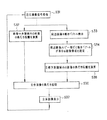
図3は本実施形態の動作を示すフロー図である。このフロー図は、図1に示す立体画像生成装置1から左右画像が出力されたのち、立体画像処理装置2による画像処理、およびHMD3による画像表示動作までを示すものである。以下、図4以降の図も適時参照しながら本実施形態の装置の動作を説明する。
【0021】
[ステップS1]
立体画像生成生装置1から出力された立体画像信号SAである左右画像信号が立体画像処理装置2に順次入力し受信される。今、図4の(a)に示す左画像フレームm−1(L)と図4の(b)に示す右画像フレームm−1(R)とを受信したのち、同図(c)に示す左画像フレームm(L)と同図(d)に示す右画像フレームm(R)とを受信したとする。
【0022】
ここに示す画像例は、図面上、右方向に走行している自動車を追尾してステレオ撮影した場合の画像例である。したがって同図(a)に対する同図(c)の自動車画像位置は変化していない。一方、背景画像は左方向に変化している。以上のことは同図(b)と同図(d)との間でも同じことが言える。
【0023】
また、カメラ近方に位置していると想定される自動車は、同図(a)に示す左画像の画像位置よりも、同図(b)に示す右画像の画像位置が左にずれている。つまり視差を持っている。一方、背景はカメラから無限遠に位置していると想定されるため、同図(a)と同図(b)の画像位置は一致している。つまり視差が0となっている。同図(c)と(d)についても同じことが言える。
【0024】
[ステップS2]
時刻の異なる画像間の動きベクトルを検出する。ここでは、左画像フレームまたは右画像フレームのいずれかを用いる。例えば左画像を用いるものとし、図4では同図(a)の画像に対する同図(c)の画像の動きベクトルを検出する。動きベクトルの検出法としては、それぞれの画像を小領域のブロックに分割し、各ブロック毎にテンプレートマッチング処理を行なう。このような処理を行なうことにより、結果として同図(e)に示す如き動きベクトルが求まる。
【0025】
この図4の(e)は、自動車の画像が位置している領域が動きベクトル0、つまり動きがなく、その他の画像が位置している領域は左方向の動きベクトルつまり左方向へ画像が変化していることを表している。
【0026】
[ステップS3]
観察者が注視するであろうと予測される画像領域(注視予測領域と呼ぶ)が決定される。具体的には、画面中にある多数の動きベクトルの中で一部だけ動きベクトルが異なる領域が選定される。図4の(e)の場合は点線枠で囲った部分だけが他の動きベクトルとは異なる。したがって、この領域が注視予測領域であると判断する。
【0027】
図4の(e)の場合とは逆に、例えば図5のように画面の一部だけが動きベクトルを有し、その他の動きベクトルが0である場合には、動きベクトルを有する領域を注視予測領域とする。
【0028】
また、図6のように、画面の一部の画像自体が変化した場合には、その変化した領域のみが動きベクトルが得られない異常値となる。この場合は、その異常値を呈した領域を注視予測領域とする。
【0029】
上記した例は、いずれも画面中に存在する多数の動きベクトルの中で、一部だけ動きベクトルが他とは異なる領域が存在している例であり、その一部だけ動きベクトルが異なる領域を注視予測領域として選定する。
【0030】
尚、図7のように、一つの画面中に一部だけ動きベクトルの異なる領域が複数(図7の場合は2箇所)存在する場合には、画面の中央に近い方を注視予測領域として選択する。また、画像がほとんど変化しない場合、動きベクトルの違いが相対的に小さく略0値となる。このような場合には、画面中央部の所定面積の領域を注視予測領域とする。
【0031】
更に、図8のように、例えば車窓から見た風景のように、画面全体が一様に一方の側から他方の側へ変化している場合には、動きベクトルが全て同じベクトル値を有する。このような場合には、画面の中央位置から動きベクトル量とは逆方向に一定幅だけシフトした位置を注視予測領域とする。すなわち観察者は動きに関して、いわば上流側(図示例では新たな画像が出現してくる左側)に注目する傾向をもつ。したがって上記の如く「動きベクトル量とは逆方向に一定幅シフトした位置」を注視予測領域とすることが妥当と言える。
【0032】
図9は、上述したステップS3における「注視予測領域決定」の判断過程を示すフロー図である。
【0033】
[ステップS4]
注視予測領域内の画像の奥行き距離を求める。画像の奥行き距離を求める方法には幾つかあるが、その代表的なもの三つを以下に例示する。
(1)相関方式;注視予測領域において左画像フレームと右画像フレームとの相関計算を行ない、視差を導出する。
(2)距離信号付加方式;画像領域毎に予め奥行き距離を表す信号を付加しておく。そして注視予測領域を選定することで、その領域に対応した奥行き距離信号を特定する。
(3)測距方式;注視予測領域の方向にある物体の奥行き距離を検出する。この検出には、ステレオカメラに設けられている測距センサや、コンピュータグラフィックスのZバッファ値を用いる。
【0034】
ここでは、上記(1)の相関方式で奥行き距離を求める場合について、前述の図4を用いて説明する。同図(f)に示すように、フレームm(L)の左画像における注視予測領域は、ステップS3で既に定まっている。そこで点線で囲った領域に対応する部分が右画像m(R)のどの位置に存在するかを相関演算することによって求める。相関演算の例としては、同図(f)の点線で囲った画像をテンプレートとし、同図(g)に示すフレームm(R)の点線で囲った画像に対してテンプレートマッチングを行なう。ここで、同図(g)の点線の領域は、同図(f)に示すように、点線の領域を中心として左右方向に拡大した領域となっている。
【0035】
相関演算した結果、例えば図10の(a)に示すように、ある相関ピーク値を有する相関シフト量から対応部分がわかる。結果として、図4の(g)の斜線を施した領域が、同図(f)の点線枠で囲った画像と対応していることがわかる。次に、同図(f)の点線領域の中心位置のX座標xLと同図(g)の斜線領域の中心位置のX座標xRとのずれ(xLーxR)を求める。ここで、X座標とは、画像の横方向の位置を示す。このずれ(xLーxR)がいわゆる視差であり、奥行き距離を表している。図10の(a)の場合においては、相関ピーク値の相関シフト量がそのまま視差(xLーxR)を示す。
【0036】
ところで図4の(f)の中に奥行きの異なる複数の画像が含まれている場合もあり得る。この場合には、相関演算の結果、複数の視差値が出力される。このような場合においては、以下のようにして最終的な視差を決定する。
(1)視差の大きい方を最終的な視差とする。つまり近方の視差を選択する。図10の(b)のように、二つある相関ピークのうち、相関シフト量の大きい方を選択する。
(2)複数の視差の平均値を最終的な視差とする。図10の(c)のように、二つある相関ピークの相関シフト量の平均値とする。
(3)視差を求める際の相関ピークの大きい方の視差を最終的な視差とする。コントラストの低い画像の場合には、左右画像の相関ピークは小さくなる。一方、コントラストがはっきりしている画像領域や、一箇所にデータ値が集まっている場合には相関ピークは高くなる。よって観察者は、後者の方を注視するものと予測し、相関ピークの高い方の画像の視差を最終的な視差とする。図10の(d)のように相関ピーク値の高い方の相関シフト量を視差とする。
【0037】
[ステップS5]
奥行き距離の信号に基づいて視距離と輻輳距離とが一致するように、立体画像の奥行き制御を行なう。この奥行き制御の制御方式は、大きく分けると次の2通りとなる。
(1)輻輳距離制御方式;左右画像を水平方向にシフトすることにより、輻輳距離が目標の輻輳距離(=視距離)となるように制御する方式。
(2)視距離制御方式;視距離が奥行き距離と一致するように視距離を制御する方式(例えば、HMD3の接眼光学系における表示素子とレンズとの距離を制御するもの等)。
【0038】
ここでは、上記 (1)輻輳距離制御方式について説明する。まず、立体画像観察時の視差と輻輳距離Lとの関係について説明する。
【0039】
図11に示すように、左表示面21の水平位置XL と右表示面22の水平位置XR とに像を表示したとき、点Bの位置でXL とXR の像は一致する。この点Bから左右の接眼レンズ23,24の主平面までの距離を輻輳距離Lとする。このときのXL とXR は次式(1)(2)で表される。
XL ={ d+(−H)}/L・tanθ …(1)
XR ={−d+(−H)}/L・tanθ …(2)
dは左右レンズの中間点(原点)から左右レンズのそれぞれの中心点(左右の主点C,E)までの距離である(右眼側は正、左眼側は負の値となる)。θはレンズの半画角である。また、−Hは、点Bの水平位置である。
【0040】
ここで、左表示面21の水平位置XL と右表示面22の水平位置XR とは、表示領域における光軸との交差点を0として、図12に示すように表示領域の水平長さを「2」として規格化している。式(1)は、図11における点A、点B及び点Cによって作られる三角形と、左表示面21での原点0と点XL と点Cとによって作られる三角形とが相似であることから導くことができる。式(2)も同様に、点D、点B及び点Eによって作られる三角形と、右表示面22での原点0と点XR と点Eとによって作られる三角形とが相似であることから導くことができる。
上記二つの式から次式が導かれる。
XL −XR =2d/L・tanθ …(3)
上式(3)は視差(XL-XR )と輻輳距離Lとの関係を表している。よって輻輳距離Lと視距離Iとが一致するための視差の条件は次式(4)で表せる。
XL −XR =2d/I・tanθ …(4)
【0041】
前記奥行き制御方式のうち、 (1)輻輳距離制御方式では、視差(XL-XR )が常に上式(4)を満たすように視差制御が行なわれる。その制御の仕方としてはステップS5で求めた視差(XL-XR )と、式(4)の差分だけ画像全体を水平方向にシフトする。その左画像のシフト量SLと右画像のシフト量SRとは例えば次式となる。
SL=−(XL −XR )+d/I・tanθ …(5)
SR=−(XL −XR )−d/I・tanθ …(6)
【0042】
ここで、SLとSRの符号「−」は左水平方向シフトを示し、符号「+」は右水平方向シフトを示している。視差(XL−XR )が目標視差よりも大きい時、つまり輻輳距離Lが視距離Iよりも近方にあるときは、左画像を右方向へシフトし右画像を左方向へシフトして、輻輳距離Lと視距離Iとを一致させる。これとは逆に視差(XL−XR )が目標視差よりも小さい時、つまり輻輳距離Lが視距離Iよりも遠方にあるときは、左画像を左方向へシフトし右画像を右方向へシフトして、輻輳距離Lと視距離Iとを一致させる。
【0043】
このステップS5ではステップS4で求めた自動車画像の視差(XL−XR )に基づいて式(5)(6)の演算を実行し、シフト量SLとSRとを求め、画像シフトを行なう。図4の例では、自動車画像の視差(XL−XR )が目標視差よりも大きい時は、同図(h)(i)に示すように左画像を左方向へシフトさせ、右画像を右方向へシフトさせる。
【0044】
[ステップS6]
立体画像処理装置2で奥行き制御された左右画像信号がHMD3に供給され、HMD3によって上記奥行き制御された左右画像信号の表示が行なわれる。
以下、これらのステップS1〜S6までが繰り返される。
【0045】
図13は、図4に示した画像例について上述した如く処理した立体画像を観察する場合の状況を示す図である。図13に示すように、自動車像が虚像面上で融像し、背景が遠方に融像した状態で、左方向へ流れていく立体画像を観察することができる。
【0046】
図14は第1実施形態における立体画像処理装置2の内部構成を示すブロック図である。尚、図14の左上に、二点鎖線で囲ったブロック60(視線検出器61からの信号を視線ベクトル演算部62で演算して出力するブロック)は、第4実施形態の構成を示すために付加された部分であり、第1実施形態の構成には直接関係がない。
【0047】
図14に示すように立体画像生成装置1からの左画像信号および右画像信号を受信すると、この左右画像信号から分離された垂直同期信号が、各ブロックの処理タイミングを制御するためのタイミング制御部31へ入力する。尚、図14に示されている符合TCは、上記垂直同期信号に相当する信号を示している。
【0048】
上記左右画像信号は、A/D変換器32,33でA/D変換された後、切換えスイッチ34,35を介してメモリ1〜メモリ5へ選択的に供給されるものとなっている。左画像信号はメモリ1とメモリ2とメモリ3のうちいずれかに記憶される。これらの各メモリへの記憶動作は、切換えスイッチ34によりフィールド毎またはフレーム毎に交互にスイッチングされながら実行される。したがって、メモリ1〜メモリ3には、1フィールド毎または1フレーム毎に異なった画像が記憶される。
【0049】
今、時刻mにおいてメモリ1には左画像m(L)が記憶され、メモリ2には左画像m−1(L)が記憶されるものとする。また、メモリ3には次のフレーム左画像m+1(L)が記憶されるものとする。
【0050】
一方、右画像もメモリ4及びメモリ5に対し、切換えスイッチ35によりスイッチングされて記憶される。ここではメモリ4には右画像m(R)が記憶され、メモリ5には右画像m+1(R)が記憶されるものとする。
【0051】
次に、メモリ1〜メモリ3のうち、二つのメモリ内に記憶されている両画像が比較され動きベクトルを演算される。時刻mではメモリ1とメモリ2とが選択され、m(L)画像信号とm-1(L)画像信号とが動きベクトル検出部へ出力される。ここで、選択されるメモリ番号は時刻に応じて順次切り替わる。(以上がステップS1に相当。尚、ステップS1では全ブロックのベクトルの各値を得てそれらの平均を求める。)
【0052】
動きベクトル検出部36は、両画像を複数のブロックに分割し、一方の画像内のブロックと相関の高いブロックをもう一方の画像内から探す。両画像におけるブロックの位置の差が動きベクトルとなる。この演算処理は各ブロック毎に行なわれ、各ベクトル信号が注視予測領域決定部37に入力する。(以上がステップ2に相当)
【0053】
注視予測領域決定部37は、前述したように図9に示すフロー図にしたがって注視予測領域の演算を行なう。以下、図9に示すフロー図について説明する。
【0054】
ステップS3ー1では、全体の動きベクトルの中で一部だけ異なるベクトルがあるか否かを判定する。この判定は先ず全体の動きベクトルの分散値を求め、その分散値が規定の値を超えるか否かを確認することによって行なわれる。ここで、分散値とは、複数に分割した各画像ブロック毎の動きベクトルのバラツキ度合をいう。
【0055】
ステップS3ー2では、ステップS3ー1で一部だけ異なるベクトルがあると判定されたとき、そのベクトル領域が一つなのか複数なのかを判定する。この判定は、動きベクトルの偏差(バラツキの幅)の90%以上偏位している動きベクトルがあるか否かを検索し、90%以上偏位している動きベクトルが存在している画面上の座標位置を見つけ、いわゆるラベリングを行ない、このラベリングを行なった数が一つか複数かで判定するものである。
【0056】
ステップS3ー3では、前記ステップS3ー2での判定結果が「一つ」である場合、当該ラベリングされた一つのブロック番号に相当する信号を注視予測領域信号として相関演算部38へ出力する。
【0057】
一方、ステップS3ー4では、ステップS3ー2での判定結果が「複数」である場合、各ラベルの中心座標を演算し、その中心座標が画面中央に近い方のラベルにおけるブロック番号に相当する信号を注視予測領域信号として相関演算部38へ出力する。
【0058】
前記ステップS3ー1において、一部だけ異なる動きベクトルは存在しないと判定された場合には、ステップS3ー5へ移る。ステップS3ー5では、全体の動きベクトルの平均値が0であるか否かを判定する。ステップS3ー6では、ステップS3ー5で全体の動きベクトルの平均値が0であると判定されたとき、予め注視予測領域決定部内に記憶されている画面中央部におけるブロック番号に相当する信号を、注視予測領域信号として相関演算部38へ出力する。ステップS3ー7では、ステップS3ー5で全体の動きベクトルの平均値が0でないと判定されたとき、上述のブロック番号を動きベクトル平均値の反対方向にシフトしたブロック番号に相当する信号を注視予測領域信号として相関演算部38へ出力する。
【0059】
以上が注視予測領域決定部37の動作である。次に相関演算部38について説明する。相関演算部38は、前記した如く注視予測領域として決定されたブロック番号を、そのままメモリ1〜メモリ3のいずれかに出力する。時刻mにおいては左画像m(L)が記憶されているメモリ1へ出力する。一方、右画像に対しては、先ほどのブロック番号に予め相関演算部38が記憶している水平冗長ブロック数分α(視差相応の見込みずれ量。これだけのマージン領域αを広げてブロック番号で特定される領域を全てカバーし得る領域Zを特定し、その上で左右のずれ量の比較を行なう必要があるからである。)を付加して、メモリ4、メモリ5のいずれかに出力する。時刻mにおいては、右画像m(R)が記憶されているメモリ4へ出力する。メモリ1とメモリ4は受信したブロック番号内の画像信号を相関演算部38に返す。そして相関演算部38は左画像信号をテンプレートにして、1ブロックづつ左画像をシフトして右画像信号との減算を行なう。ここで、減算値が小さいほど相関値は高い。相関演算部38は、各シフト量に対する減算値を視差演算部39へ出力する。
【0060】
視差演算部39では、図10に示す視差決定法に基づき、減算値を利用して最終的な視差値を求める。視差値はシフト量演算部40へ出力される。(ステップ4に相当)
【0061】
シフト量演算部40では、式(5)(6)の演算を行なって左画像用シフト量と右画像用シフト量を求める。各シフト量は左右それぞれの画像読み出し制御部41,42へ出力され、各画像読み出し制御部41,42は、各メモリ内の画像信号をシフト量だけシフトして読み出す。(ステップ5に相当)
【0062】
読み出された左右画像信号は、D/A変換器43,44によりそれぞれD/A変換されたたのち、HMD3の左右表示素子にそれぞれ供給されて表示される。(ステップ6に相当)
【0063】
上述した第1実施形態は、動きベクトルを検出し、画面中において一部だけ画像の変化が異なる領域を求め、その領域内にある画像の奥行き距離を求め、立体画像観察における視距離と輻輳距離とが合致するよう制御するものである。本実施形態によれば、視線検出器を用いる必要がないので、装置全体を小型に、しかも安価に得ることができる。
【0064】
「第2実施形態」(左右画像の動きベクトル検知)
第1実施形態では動きベクトルを左右画像の一方のみについて求めたが、この第2実施形態では、第1実施形態の一部を変形し、左右画像の双方に動きベクトルを求めるようにしたものである。
【0065】
図15に示す画像例では、同図(a)(c)に示す左画像について同図(e)に示す動きベクトルを求めると共に、同図(b)(d)に示す右画像についても同図(f)に示す動きベクトルを求める。そして、同図(g)(h)に示すように、それぞれの注視予測領域を決定する。
【0066】
次に、それぞれの注視予測領域の中心座標xL、xRを求める。そして、これらの座標xLとxRとの差(xLーxR)を視差と定める。このように第2実施形態では相関演算を行なわない。
【0067】
図16は第2実施形態における立体画像処理装置の内部構成を示すブロック図である。左右画像ともに、注視予測領域決定部37までは共通である。このため共通部分は二点鎖線で囲み一方を省略した。左右それぞれの注視予測領域決定部37からは中心座標値xLとxRとが視差演算部39へ出力される。視差演算部39では(xL−xR)を行ない、その結果をシフト量演算部40へ出力する。後の処理は第1実施形態の場合と同じなので説明は省略する。
【0068】
本実施形態では、相関演算を行なわずに視差量を求め得るので、処理時間を短くて済むというメリットがある。
【0069】
「第3実施形態」(フィールド順次対応)
第3実施形態は、第1実施形態の一部を変形し、フィールド順次(またはフレーム順次)立体映像に対して有効なものとした例である。すなわち、時刻の異なる左右画像間の動きベクトルを検出し、注視点を予測して視差を求めるようにする。
【0070】
図17は第3実施形態の処理動作を示すフロー図である。このフロー図について、図18に示す画像処理例を参照しながら説明する。尚、本実施形態では、図18の(a)(b)(c)に示すように、右画像フレーム番号m−1(R)、左画像フレームm(L)、右画像フレームm+1(R)…と言う具合に、左右画像を交互に受信するものとする。
【0071】
[ステップS11]
左画像フレームm(L)を受信する。
[ステップS12]
右画像フレーム番号m−1(R)に対する左画像フレームm(L)の動きベクトルmをブロック毎に求める。すなわち隣接フィールド区間どうしの比較(左用フィールドと右用フィールドとの間の比較)で動きベクトルを求める。したがってこの結果は左右の視差を含んだものとなる。図18の(d)は上記結果例を示す。背景画像については左方向の動きベクトルが現れる。また、車の画像領域については視差分の動きベクトルが現れる。
[ステップS13]
右画像フレームm+1(R)を受信する。
【0072】
[ステップS14]
左画像フレーム番号m(L)に対する右画像フレーム番号m+1(R)の動きベクトルをブロック毎に求める。図18の(e)はその結果例を示す。背景画像については、(d)と同様に左方向の動きベクトルが現れる。一方、車の画像領域については、(d)とは逆方向の視差分の動きベクトルが現れる。
【0073】
[ステップS15]
図18の(d)の動きベクトルと、同図(e)の動きベクトルとについて、ブロック毎の平均値を求める。等速運動をする物体については視差分がキャンセルされるためこのようにする。図18の(f)はその結果を示している。背景画像については左方向の動きベクトルが現れ、車の画像に関しては動きベクトルが0となる。
【0074】
[ステップS16]
得られた動きベクトルの平均を用いて第1実施形態と同様の注視予測領域の決定を行なう。図18の場合には、等速運動をする物体については視差分がキャンセルされるため動きベクトルが0値である領域を注視予測領域とする。
【0075】
[ステップS17]
図18の(d)の動きベクトルから同図(e)の動きベクトルをブロック毎に差分し1/2にする。こうすることにより背景に関する動きがキャンセルされ、視差ベクトルが現われる。図18の(g)はその結果を示している。図示の如く背景画像についてはベクトル値が0となり、車の画像に関しては右方向の視差ベクトルが現れる。この視差ベクトル値が車の画像の奥行き情報となる。
この後のステップは第1実施形態の場合と同じであるため説明を省略する。
【0076】
図19は第3実施形態における立体画像処理装置の内部構成を示すブロック図である。フィールド毎に交互に受信した左右画像信号はA/D変換器50によりA/D変換されたのち、メモリ1、メモリ2、メモリ3に記憶されていく。
【0077】
今、時刻mにおいて、メモリ1にはフィールド画像m(L)が記憶され、メモリ2にはフィールド画像m−1(R)が記憶されており、そして次のフィールド画像m+1(R)がメモリ3に記憶されるものとする。三つのメモリのうち二つのメモリが選択され、その内容が動きベクトル検出部36へ出力される。
【0078】
時刻mにおいては、メモリ1とメモリ2とが選択され、読み出された画像信号が動きベクトル検出部36に入力する。動きベクトル検出部36は、選択された二つのメモリの画像における動きベクトルを検出して出力する。この出力された動きベクトルは第1動きベクトルメモリ51に記憶される。次の時刻m+1になると、メモリ1とメモリ3とが選択され、両画像の動きベクトルが検出される。この検出された動きベクトルは第2の動きベクトルメモリ52に記憶される。
【0079】
次に、第1,第2の動きベクトルメモリ51,52に記憶されている各動きベクトルの信号は、動きベクトル加算器53へ出力される。動きベクトル加算器53で加算された結果は、注視予測領域決定部37へ出力される。注視予測領域決定部37は、図14に示す第1実施形態の構成ブロック図における注視予測領域決定部37と同じ働きをする。注視予測領域決定部37は、演算結果が相対的に特異な値を示す領域を識別し、その領域のブロック番号を視差演算部39へ出力する。
【0080】
一方、第1,第2の動きベクトルメモリ51,52に記憶されている各動きベクトルは、動きベクトル減算器54にも出力される。この動きベクトル減算器54による減算結果は視差演算部39へ出力される。視差演算部39では、注視予測領域決定部37から受信したブロック番号における動きベクトルと動きベクトル減算器54から受信した減算の結果とに基づいて視差を決定する。決定された視差信号は、シフト量演算部40へ出力され、シフト量が演算される。この演算されたシフト量に応じて、メモリ1〜メモリ3に記憶されている画像が、表示用読み出し制御部55によってシフトされた状態で読み出される。読み出された画像は、D/A変換器56でD/A変換された後、切替え器57によりフィールド毎に左表示素子と右表示素子への出力に切替られて送出される。
【0081】
第3実施形態においては、フィールド順次立体画像に対応する如く構成されており、第1実施形態における相関演算部38の働きを、動きベクトル検出部36が兼ねた構成となっているため、全体のブロック数が少なくて済み、安価に製作できるという利点を持つ。
【0082】
「第4実施形態」(視線動きベクトルを利用)
第4実施形態は、第1実施形態の一部を変形し、動画像間の動きベクトルと観察者の視線の動きベクトルとを検出し、両者の比較から注視予測領域を決定するようにした例である。
【0083】
観察者の視線の動きベクトルを検出する方法として、HMD3に設けた視線検出器を利用する。ただしこの視線検出器は、従来用いられていたような、視線の絶対座標を調べるのものではなく、視線の相対的な変動を検出する目的で用いるものである。よって高精度なものである必要はなく、また、視線の絶対座標を割り出すためのキャリブレーション等も不要である。
【0084】
図20は第4実施形態の動作を示すフロー図である。図3に示した第1実施形態の動作を示すフロー図との比較から分かるように、「観察者の視線の動きベクトルの検出」(ステップS23)が新たに加わったことと、「立体画像の奥行き制御」(ステップS5)の代わりに「視距離と輻輳距離との合致制御」(ステップS26)が加わったことの二点が大きく異なるだけで他はほぼ同様である。
【0085】
第1実施形態の場合と同様に、まず動きベクトルを検出し、同時に観察者の視線の動きベクトルを検出する。そして全体の動きベクトルの中で、視線の動きベクトルと同じベクトルを有する画像領域を決定し、この画像領域を注視予測領域とする。
【0086】
尚、ステップS23における「観察者の視線の動きベクトルの検出」は、視線方向角の変化Δθを精度よく検出することは比較的容易であるが、視線方向の絶対値を検出することは困難である。したがって本実施形態では、上記Δθに相応する動きベクトルが、画面内のブロックのいずれの位置に対応するかに基づいて注視予測領域を特定することにした。この結果、例えば図21の(c)に示すような動きベクトルが現れる。
【0087】
次に、フレーム間での視線の動きベクトルを検出する。その検出の結果、視線の動きベクトルが、例えば図21の(d)に示す如く右向きであれば、図21の(c)に示す如く、注視予測領域は動きベクトルが右向きの領域となる。
【0088】
第4実施形態における立体画像処理装置の内部構成を示すブロック図は、図14の左上に、一点鎖線で囲ったブロック60(視線検出器61からの信号を視線ベクトル演算部62で演算して出力するブロック)が付加された状態の全体ブロック図に相当するものとなる。
【0089】
第4実施形態は、第1実施形態のように画像のみから注視予測領域を決定するのではなく、視線の動きを検出する視線検出器61を用いて注視予測領域を決定するように構成されているので、注視する領域が観察者によって大きく変わる場合であっても、より的確に対応できるという利点を持つ。
【0090】
「第5実施形態」(周辺のみの動きベクトル)
第5実施形態は、第1実施形態の一部を変形し、動きベクトルを画像の周辺のみについて検出し、画像周辺において、一部だけ動きベクトルの異なる領域がある場合には、その領域を注視予測領域となし、ない場合には画面中央を注視予測領域とするものである。
【0091】
図22は第5実施形態の動作を示すフロー図である。また、図23は上記フロー図の説明に用いる処理画像例を示す図である。
[ステップS31]
左右画像信号を、例えば図23の(a)(b)(c)(d)の順で順次受信する。
[ステップS32]
画像中央領域内の画像に対する奥行き距離を演算する。図23の(e)(f)に示すように、左右画像の中央領域の画像を用いて相関演算を行ない、視差1を求める。
[ステップS33]
画像領域の周辺画像についてのみ、動きベクトルを検出する。図23の(g)に示すような動きベクトルが表れる。
【0092】
[ステップS34]
第1実施形態の注視予測領域決定と同じ処理を用い注視予測領域を選定する。すなわち周辺画像領域内における特異な動きベクトルを示す領域を特定(判定)する。図23の(g)における点線で囲んだ部分が注視予測領域となる。
[ステップS35]
第1実施形態の場合と同様に、上記注視予測領域に関する奥行き距離を演算する。図23の(h)(i)に示すように、相関演算を行ない視差2を求める。
[ステップS36]
ステップS32で得られた画像中央奥行き距離と、ステップS35で得られた注視予測領域奥行き距離とに基づいて、立体画像の奥行き制御値を決定する。その決定方法としては、図10に示した決定方法と同じ方法を用いる。
【0093】
尚、ステップS34で、一部だけ動きベクトルの異なる画像領域が見つからなかった場合には、画像中央の奥行き距離をもって奥行き制御を行なう。また、ステップS34で、一部だけ動きベクトルの異なる画像領域が見つかった場合には、図23に示した二つの視差値、つまり視差1と視差2とを用い、以下の三つの方法により最終視差値を求める。
(1)観察者からみて手前側にある画像を注視するであろうという判断に基づいて、視差の大きい方を最終的な視差とする。
(2)どちらも見ている場合もあり得るため、そのようなケースに対応する為、複数の視差の平均値を最終的な視差とする。
(3)相関比較においてマッチングの度合いが高い方、はっきりした画像部分に注目するであろうという判断に基づき、視差を求める際の相関ピークが大きい方の視差を最終的な視差とする。
この後の処理は第1実施形態の場合と同じである。
【0094】
図24は第5実施形態における立体画像処理装置の内部構成を示すブロック図である。図14に対して以下の点が異なっている。
【0095】
一対のA/D変換器32,33によるA/D変換後の左右画像信号がそれぞれ二つに分岐される。そして一方の左右画像信号は、図14の場合と同じ処理が行なわれる。ただし動きベクトル検出は周辺画像についてのみ行なわれる。周辺画像の動きベクトル検出部36は周辺部データの抽出と、抽出したデータ値の比較(動き検出)との双方を行なう。すなわち動きベクトル検出部36は、メモリ1〜メモリ3から周辺画像信号のみを受信し、動きベクトルを検出した後、注視予測領域決定部37へ供給される。
【0096】
他方、分岐されたもう一方の左右画像信号は、画像中央抽出部71によって画像中央の画像信号のみを抽出される。抽出された画像中央の画像信号は、相関演算部72に入力し、画像中央のみについての左右画像の相関演算が行なわれる。その結果は視差演算部39に出力される。視差演算部39では、上記相関演算部72および図14で説明した相関演算部38からの相関演算の結果を用い、前述した決定方法により最終視差値を決定する。この後の処理は第1実施形態の場合と同じである。
【0097】
本実施形態では、画像周辺部だけの動きベクトルの検出と、最も注視する確率の高い画像中央部の奥行き距離の演算とが同時平行して行なわれることから、全体の処理時間を大幅に短縮できるという利点がある。また、本実施形態においては前記最終視差値を求める三つの方法(1)(2)(3)が加味された注視予測領域の弁別が行なわれる為、より目的に合致した判別がなされ得る利点がある。
【0098】
「第6実施形態」(精度の低い視線検出器で選択)
第6実施形態は、第1実施形態の一部を変形し、注視予測領域決定において、動きベクトルの異なる領域が複数存在する場合に、視線検出器での観察者の視線信号を用いて、複数のうちどれかを決定する。ここで用いる視線検出器は、絶対座標として視線位置が可能であるが,検出角度精度が±5°程度のかなり低い精度のものでも使用可能である。
【0099】
図25の(a)〜(c)に示すように、動きベクトルの異なる二つの領域M,Nがある場合において、観察者が同図(d)に示すように、画面中央下部を見ているという情報を精度の低い視線検出器(例えば角度精度±5°程度のもの)で検出したとき、当該画面中央下部の領域内にある方の動きベクトルを選択するものである。
【0100】
本実施形態は、第1実施形態のように画像だけから注視予測領域を決定するものではないので、注視する領域が観察者によって大きく変わる場合においても、的確に対応できるという利点を持つ。
【0101】
「第7実施形態」
本実施形態では、第1実施形態で用いた動きベクトルの代わりにエッジ差分画像を用い、画面中において一部だけ画像の変化が異なる領域を求め、その領域を観察者が注視するであろうと予測する。その後、第1実施形態と同様に注視予測領域内にある画像の奥行き距離を求め、立体画像観察における視距離と輻輳距離とが合致するように制御する。
【0102】
この第7実施形態に係る立体画像表示装置の構成(概要)は、図1及び図2に示した第1実施形態の構成と同じなので、その説明は省略する。
【0103】
図26は第7実施形態の動作を示すフロー図である。このフロー図は、図1に示す立体画像生成装置1から左右画像が出力されたのち、立体画像処理装置2による画像処理、およびHMD3による画像表示動作までを示すものである。以下他の図も適時参照しながら本実施形態の装置の動作を説明する。
【0104】
[ステップS41]
立体画像生成装置1から出力された左右画像信号は、立体画像処理装置2に順次受信される。今、第1実施形態と同様に、図4の(a)(b)に示す左画像フレームm−1(L)と右画像フレームm−1(R)を受信した後、同図の(c)(d)に示す左画像フレームm(L)と右画像フレームm(R)とを受信したとする。これらの画像は既に説明したように、自動車は画面上の所定位置にあって動かず背景のみが移動する画像である。
【0105】
[ステップS42]
立体画像処理装置2は受信した画像を順次エッジ抽出を行ない、エッジ画像を生成する。図27の(a)(b)(c)(d)は、それぞれ図4の(a)(b)(c)(d)に対応するエッジ画像である。これらのエッジ画像は2値化されており、エッジ部分が「1」で、それ以外が「0」である。
[ステップS43]
フレーム間におけるエッジ画像の変形部分を検出する。検出方法として、現フレームのエッジ画像から前フレームのエッジ画像を減算し差分画像を生成する。ここで差分の結果、負の値となるものは0値とする。
【0106】
図27の場合は、同図(c)の左画像フレームm(L)のエッジ画像から同図(a)の左画像フレームm−1(L)を減算する。同図(e)は減算により得られた画像を示している。同図(e)に示す如く、静止した車の画像は消える。また、結果がマイナスになるところの画像も消える。また、右画像フレームについても同様に、同図(d)の右画像フレームm(R)のエッジ画像から同図(b)の右画像フレームm−1(R)を減算する。同図(f)は減算により得られる画像を示している。どちらも背景画像に関するエッジ画像が抽出されている。ステップS43の処理により生成される画像を、本実施形態では「変形エッジ画像」と呼ぶことにする。
【0107】
[ステップS44]
このステップS44では、フレーム間において変形していない部分の検出を行なう。その検出方法としては、現フレームのエッジ画像からステップS43で検出した変形エッジ画像を減算し、差分画像を生成する。図27の(g)(h)はそれぞれ同図(c)から(e)を減算した画像と、同図(d)から(f)を減算した画像である。どちらも自動車に関するエッジ画像が抽出されている。
ステップS44の処理によって生成される画像を、本実施形態では「固定エッジ画像」と呼ぶことにする。
【0108】
[ステップS45]
このステップS45は第1実施形態のステップS3の注視予測領域の決定に相当する。本実施形態では、ステップS43で求めた変化エッジ画像と、ステップS44で求めた固定エッジ画像のうち、どちらに観察者が注目する画像情報が入っているかを予想する。その予想は、エッジが一箇所に集中している方を注視するものと予測する方法を用いて行なう。
【0109】
具体的な処理方法としては、「1」の値を示す点の画像内での分布状況を検出する。しかるのち変形エッジ画像と固定エッジ画像のいずれの分布の広がりが小であるかを判別する。これは分布の小さい方が画面内における特異な領域である蓋然性が高いとの思想に基づいている。そこで分布の広がりの小さい方を選ぶ。分布の広がりがほぼ同じ場合には平均値がより画像中央座標に近い方を選ぶ。
【0110】
図28の場合には、同図(e)と(g)を比較し、(g)の方がエッジの分布の広がりが小さいので、固定エッジ画像である(g)を選択する。同様に右画像についても同図(f)と(h)を比較し、(h)の方がエッジの分布の広がりがが小さいので、固定エッジ画像である(h)を選択する。勿論、図28のように自動車が画面上を移動する画像の場合には、変形エッジ画像である同図(e)又は(f)を選択する。
【0111】
このように変形エッジ画像又は固定エッジ画像を選択し、選択したエッジ画像における上記平均座標値を中心とした予め定めた面積の領域を注視予測領域とする。
【0112】
図27の場合には、同図(g)(h)に示した点線で囲んだ領域を注視予測領域とする。
また、変形エッジ画像と固定エッジ画面とのいずれかのデータ数の総和(例えば小区分毎に弁別するときの全画面について「1」となる箇所の総和)が予め設定したデータ数よりも少ない場合には、他方の画像を選択する。つまり少ない方の画像は判断の基礎として用いない。これは画面全体が一様に変化している場合や静止画の場合に適応可能とする為である。
【0113】
例えば、図29に示すように、画面が一様に変化する場合には、変形エッジ画像である同図(e)(f)は、ほぼ現フレームのエッジ画像(c)(d)と同じであり、固定エッジ画像である(g)(h)はエッジが現れない。この場合には(g)(h)のデータ数の総和は小さいので変形エッジ画像である(e)(f)が選択される。
【0114】
一方、図30に示すような静止画の場合には、図29とは逆になる。すなわち変形エッジ画像である(e)(f)はエッジが現れない。この場合には、固定エッジ画像である(g)(h)が選択される。
【0115】
このように変形エッジ画像か固定エッジ画像かを選択し、選択したエッジ画像において予め定めてある画面中央領域を注視予測領域とする。前記した図29の場合は、(e)(f)の点線で囲んだ領域が注視予測領域である。
【0116】
図31は、上述したステップS45における画像選択操作を示すフロー図である。本実施形態のように変形エッジ画像と固定エッジ画像とを生成し、いずれを注視するかについて自動認識することにより、上記のような各種画像に幅広く対応できる。
【0117】
図26に説明を戻す。
[ステップS46]
ステップS45で選択した方の画像について奥行き距離を求める。奥行き距離の求め方は第1実施形態のステップS4と同様である。
[ステップS47]
奥行き距離の信号に基づいて視距離と輻輳距離とが合致するように制御する。この制御の方法は第1実施形態のステップS5と同様である。
[ステップS48]
左右画像を表示する。第1実施形態のステップS6と同じである。
以下、これらステップS41〜S48までを繰り返す。
【0118】
図32は第7実施形態における立体画像処理装置の内部構成を示すブロック図である。尚、図32において、二点鎖線枠で囲んだ左右画像に対応する前処理部は同じ構成であるため、右画像側内部構成の図示を省略した。
【0119】
立体画像生成装置1から到来した左右画像信号は、一方においてA/D変換器32,33によりA/D変換されたのち、前処理部80,90に入力する。上記左右画像信号から分離された同期信号は、各ブロックの処理タイミングを制御するためのタイミング制御部31へ供給される。
【0120】
前処理部80に入力した左画像信号は、スイッチ34により各フレーム毎にスイッチングされて、メモリ1〜メモリ3のいずれかに記憶される。このため各メモリには1フレーム毎に異なった画像が記憶される。時刻mにおいて、メモリ1には左画像m(L)が記憶され、メモリ2には左画像m−1(L)が記憶されたとする。又メモリ3には次のフレーム左画像m+1(L)が記憶されるものとする。右画像についても左画像と同じである。(ステップS41に相当)
【0121】
次に、メモリ1〜メモリ3から読み出された各画像は、スイッチ81を介してエッジ処理部82へ順次入力し、ここでエッジ画像が生成される。上記エッジ処理は、前述したようにエッジ部分を「1」、それ以外を「0」とする2値化処理である。生成されたエッジ画像は、変形エッジ画像生成部83と固定エッジ画像生成部84へと出力される。(ステップS42に相当)
【0122】
変形エッジ画像生成部83では、順次受信されるエッジ画像を用いて、エッジ画像の減算を行なう。時刻mにおいては、変形エッジ画像生成部はm−1(R)のエッジ画像を記憶しており、今受信したm(R)のエッジ画像からこのm−1(R)のエッジ画像を減算する。この減算したエッジ画像信号を固定エッジ画像生成部84と注視予測領域決定部85へ出力する。(ステップS43に相当)
【0123】
固定エッジ画像生成部84では、順次受信するエッジ画像について、変形エッジ画像生成部83から順次受信する変形エッジ画像を減算し,固定エッジ画像を生成する。生成された固定エッジ画像は注視予測領域決定部85へ出力される。(ステップS44に相当)
【0124】
注視予測領域決定部85では、変形エッジ画像と固定エッジ画像とを用いて注視予測領域を決定する。この注視予測領域決定部85では、図31に示すフローに基づいた注視予測領域の演算が行なわれる。結果として、注視予測領域のエッジ画像が相関演算部38へ出力される。右画像においても同様の処理が行なわれ右画像の注視予測領域のエッジ画像が相関演算部38へ出力される。(ステップS45に相当)
【0125】
相関演算部38では、左右のエッジ画像の相関演算が行なわれる。この相関演算は、第1実施形態の相関演算と同じであるため説明を省略する。結果として、相関シフト量に対する相関値が視差演算部39へ出力される。視差演算部39では、第1実施形態と同様の作業を行ない最終的な視差値を求める。視差値はシフト量演算部40へ出力される。(ステップS46に相当)
【0126】
シフト量演算部40は、第1実施形態と同様に、式(5)(6)の演算を行なって、左画像用シフト量と右画像用シフト量とを求め、各シフト量を左右それぞれの画像読み出し制御部41,42へ出力する。各画像読み出し制御部41,42は、各メモリ内の画像信号をシフト量分だけシフトして読み出す。(ステップS47に相当)
【0127】
この様にシフトして読み出された左右画像信号は、D/A変換器43,44によりD/A変換されたのち、HMD3内の左右表示素子に供給され表示される。(ステップS48に相当)
【0128】
第7実施形態は、エッジ画像の差分を検出し、画面中において一部だけ画像の変化が異なる領域を求め、その領域内にある画像の奥行き距離を求め、立体画像観察における視距離と輻輳距離とが合致するよう制御するものである。本実施形態によれば、視線検出器を用いる必要がないので装置全体を小型にでき、安価に製作し得る。また、本実施形態では差分演算処理を用いるので、動きベクトルを用いる第1実施形態に比べると、処理時間が速いという利点がある。
【0129】
「第8実施形態」(固定・変形ともに視差を求める)
この第8実施形態は、第7実施形態の一部を変形した例である。前記第7実施形態では、変形エッジ画像と固定エッジ画像との選択において、エッジデータ値が一箇所に集まっている方を選んだが、この第8実施形態では、変形エッジ画像に関する視差と、固定エッジ画像に関する視差とを比較し、その比較結果を最終的な視差とするものである。
【0130】
図33を用いて説明する。同図の(e)(f)で示した変形エッジ画像と、同図の(g)(h)で示した固定エッジ画像とを導くところまでは、第7実施形態と同じである。次に左右の変形エッジ画像を相関演算して視差を求めると共に、左右の固定エッジ画像を相関演算して視差を求める。そして、求めた二つの視差値を用いて最終的な視差量を決定する。その決定は以下に示す如く第7実施形態の場合と同様の決定方法による。
【0131】
(1)視差の大きい方を最終的な視差とする。つまり近方の視差を選択する。図33の場合には、固定エッジ画像の視差を最終的視差とする。
(2)変形エッジ画像の視差と固定エッジ画像の視差との平均値を最終的な視差とする。
(3)視差を求める際の相関ピークの大きい方の視差を最終的な視差とする。背景画像のようにデータ値が画面全体に散らばっている場合には、左右画像の相関ピークは小さくなる。一方、コントラストがはっきりしている画像領域や、一箇所にデータ値が集まっている場合には、相関ピークは高くなる。よって観察者は後者の方を注視すると予測し、相関ピークの高い方の画像の視差を最終的な視差とする。図33の場合には、固定エッジ画像の視差を最終的視差とする。
【0132】
図34は第8実施形態における立体画像処理装置の内部構成を示すブロック図である。尚、左右画像ともに変形エッジ画像と固定エッジ画像とを求めるまでは、第7実施形態におけるブロック図と同じである。その後、左右の変形エッジ画像を受信し相関を行なう変形エッジ画像相関演算部101と、左右の固定エッジ画像を受信し相関を行なう固定エッジ画像相関演算部102とが、第7実施形態の注視予測領域決定部65および相関演算部38の代わりに加わっている。
【0133】
第8実施形態においては、注視予測領域決定とその後の相関演算作業を行なう代わりに、二つの相関演算作業を同時に並行して行なえるので、処理時間が速くなるという利点がある。
【0134】
「第9実施形態」(太線エッジ画像を用いて変化の大きさを分別)
この第9実施形態は、第7実施形態の一部を変形したものである。この第9実施形態では、動画像の中から変化のない画像と、少し変化する画像と、大きく変化する画像との三つの画像を抽出して分割する。そして三つの画像から観察者が注視するであろう画像を選択する。その方法を実行するために、エッジ画像として新たにエッジ線の太いエッジ画像を追加生成する。
【0135】
図35はその画像例である。同図の(a)(b)(c)(d)は、それぞれ受信したm−1(L)画像、m−1(R)画像、m(L)画像、m(R)画像、の各エッジ画像である。ここで画像内の円は動きのない画像であり、自動車画像は画像間で大きな変化のある画像であり、それ以外の背景画像は画像間で少し変化する画像である。また、同図の(e)(f)(g)(h)は、同図の(a)(b)(c)(d)の各エッジ画像を、公知の太線化処理によって太線化した画像である。
【0136】
次に、通常のエッジ画像を用いて画像間で変化のないエッジ画像を生成する。生成方法としては、通常のエッジ画像間の乗算を行なう。図35の場合には、同図の(a)と(c)との乗算を行ない、結果として同図(i)を得る。変化のない画像部分は乗算しても値は「1」となり、変化のある画像部分は乗算すると値は「0」となり、結果として変化のないエッジ画像部分だけが抽出される。結局ここでは円のエッジ画像だけが残る。同様に、同図の(b)と(d)の乗算を行ない、結果として同図の(j)を得る。ここで生成した画像を固定エッジ画像と呼ぶことにする。
【0137】
次に、現フレームの太線化エッジ画像から前フレームの太線化エッジ画像を減算し、差分画像を生成する。差分の結果、負の値となるものは0値とする。図35の場合、同図(g)に示したフレームm(L)の太線化エッジ画像から,同図(e)に示したフレームm−1(L)の太線化エッジ画像を減算する。この減算の結果得られる画像は同図(k)に示すものとなる。つまり減算の結果として、動きのないエッジ画像は消去され、動きが大きい画像ほどエッジ線の太い画像が得られる。これは動きが大きいほど両画像のエッジのずれが大きくなるためである。又右画像フレームについても同様の処理を行なうことにより、同図の(l)に示す画像が得られる。
【0138】
次に、太線化エッジ画像の差分画像を、予め定めたエッジ線幅を基準として、エッジ線の幅の違いにより二つに分別する。
太線化エッジ画像による動き検出では、その線幅内での微細な動きに関しては動き幅を含んだ情報(もとの線幅に対し減算によりオーバラップ部については減じられるが、残る線幅部分があるため、この線幅で微細な動きの程度を計り知ることができる)を得ることができる。第7実施形態のように、細線のみで動き検出を行なうと、微細な動きに対しても直ちに対応するエッジ部(細線)のオーバラップ状態から抜け出るために、太線同士のオーバラップ部は生じず、動き幅(程度)に関する情報は得られないことになる。
【0139】
図35の(k)の画像の中からエッジ線の細い画像部分だけを抽出することにより、同図の(m)が得られる。また、エッジ線の画像部分だけを抽出することにより、同図の(o)が得られる。エッジ線の細い画像は、少し変化のある画像であり、ここでは小変形エッジ画像と呼ぶ。他方、エッジ線の太い画像は、大きな変化のある画像であり、ここでは大変形エッジ画像と呼ぶ。
右画像についても同様の処理を行なうことにより、同図の(n)及び(p)が得られる。
【0140】
次に、上述の如く得られた固定エッジ画像と、小変形エッジ画像と、大変形エッジ画像とを用いて、第7実施形態におけるステップS45と同じ処理を行なうことにより、注視予測領域を決定する。図35の場合には大変形エッジ画像が選択される。後の処理は第7実施形態と同じである。
【0141】
図36は第9実施形態における立体画像処理装置の内部構成を示すブロック図である。第7実施形態におけるブロック図(図32)と異なる点は、変形エッジ画像生成部83の代わりに、エッジ線太線化部111と、差分画像生成部112と、エッジ線幅検出部113と、小変形エッジ画像生成部114と、大変形エッジ画像生成部115とが組み込まれている点である。第9実施形態においては、画像を、固定エッジ画像と、小変形エッジ画像と、大変形エッジ画像との3種類に分別した例を示したが、エッジ線幅の分別判断を更に細かくし、4種類、5種類〜…と増やしても良い。すなわち図36に示されている小変形エッジ画像生成部114および大変形エッジ画像生成部115を、「小変形エッジ画像生成部」「中変形エッジ画像生成部」「大変形エッジ画像生成部」〜…という具合に増設する事により実現可能である。このようにエッジ画像の種類を増やすほど、画像の変化の大きさをより細かく分別することが可能となる。
【0142】
第9実施形態によれば、画像の変化の大きさに応じて画像を分別することができるため、注視予測領域をより正確に決定することが出来る。
【0143】
「第10実施形態」(ラインメモリ)
この第10実施形態は第7実施形態の一部を変形したものである。第10実施形態では、第7実施形態と同様のシフト量演算結果に応じて画像データ伝送路に介挿されたラインメモリの読み出しタイミングを制御する事によって、左右各出力段のD/A変換器に供給される当該画像データに対し、所要の視差に対応したシフトを与える。
【0144】
図37は第10実施形態における立体画像処理装置の内部構成を示すブロック図である。この実施形態では画像信号そのものを記憶しておく必要がないので、第7実施形態で必要としたメモリ1〜メモリ3が不要となる。その代わり画像シフトを行なう為のラインメモリ120を用意する必要がある。画像信号は二つに分岐され、一方はエッジ処理部へ供給され、もう一方はラインメモリ120へ供給される。そして第7実施形態と同様の処理が行なわれ、求めたシフト量の信号は左右表示用画像読み出し制御部41,42に出力される。ここでラインメモリ120に記憶されているのは画像mではなく数フレーム後の画像である。
【0145】
第10実施形態は、視差が大きく変化しない立体画像に対しては有効である。そしてメモリとしてはラインメモリ120だけでよいので安価に製作できるという利点をもつ。
尚、全実施形態において、立体画像処理装置2の左右画像信号を直接立体画像表示器3に出力するのみならず、一旦、記録媒体に左右画像信号を記録して、その後、この記録媒体中の左右画像信号を読み出して立体画像表示器3で表示しても良い。
【0146】
以下、前述実施形態に示された本発明の構成と効果を列挙する。
【0147】
[1](全実施形態に対応)
(構成)
立体画像を表わす信号の供給を受けるための入力手段(31,32,33,メモリ等)と、上記入力手段により受けた信号による立体画像の経時的な変化を検出する画像変化検出手段(36)と、上記画像変化検出手段による検出結果に基づいて画像領域中の特定の部分領域を観察者が注視する蓋然性の高い領域として指定する注視予測領域決定手段(37)と、上記注視予測領域決定手段によって指定される特定の部分領域内に表示される画像の奥行きを表わす情報を得る奥行き検出手段(38,39)と、上記奥行き検出手段により得た画像の奥行きを表わす情報に基づいて、上記入力手段により受けた信号による立体画像の奥行きに係る量を制御する奥行き制御手段(40)と、上記奥行き制御手段によって上記奥行きに係る量が制御された立体画像を表わす信号を適用された立体画像表示手段(3)に被表示立体画像信号として出力し得る出力手段(41,42)と、を備えてなることを特徴とする立体画像表示装置。
【0148】
(効果)
立体動画像の経時的変化が検出され、その変化に基づいて観察者が注視するであろう画像領域が決定され、その画像領域内にある像の奥行き情報から立体動画像の奥行きが制御されるので、検出精度の高い視線検出器を使うことなしに観察者にとって見やすい立体動画像が得られる。
【0149】
[2](第1〜第3実施形態および第5〜10実施形態に対応)
(構成)
前記注視予測領域決定手段は、前記画像変化検出手段による検出結果に基づいて被検出画像全体の中で特異な検出結果が得られる特定の部分領域が存在するときには当該特定の部分領域を当該注視予測領域として指定し、特異な検出結果が得られる特定の部分領域が存在しないときには予め設定した所定領域を当該注視予測領域として指定するように構成されたものであることを特徴とする[1]に記載の立体画像表示装置。
【0150】
(効果)
画像の中で像の変化が異なる領域が検出され、その領域が注目されるものと予測されるので、いろいろなシーン(画像が一部動いている、画像が一部変化していない、一様に変化する、静止画)にも適切に対応できる。
[3](第1〜第3実施形態および第5、第6実施形態に対応)
【0151】
(構成)
前記画像変化検出手段は、被検出画像全体を複数の各小領域に分割してなる該複数の各小領域毎に、画像の経時変化を検出する画像動き量検出手段を有してなり、且つ前記注視予測領域決定手段は、前記複数の小領域のうち画像変化検出手段によって検出される画像の経時変化の値が特異な値を示す小領域を当該注視予測領域として指定するように構成されたものであることを特徴とする[2]に記載の立体画像表示装置。
【0152】
(効果)
画像の中で像の変化が異なる領域を検出し、その領域を注視予測領域と定めるので、いろいろなシーン(画像が一部動いている、画像が一部変化していない)にも適切に対応できる。
【0153】
[4](第4実施形態に対応)
(構成)
前記画像変化検出手段は、被検出画像全体を複数の各小領域に分割してなる該複数の各小領域毎に画像の経時変化を表わす動きベクトルを検出する動きベクトル検出手段を有してなり、且つ、前記注視予測領域決定手段は、前記複数の小領域のうち前記画像変化検出手段によって検出される自己の動きベクトルが適用された視線検出手段によって検出された観察者の視点の動きを表わす視点動きベクトルに、実質的に等しい小領域を当該注視予測領域として指定するように構成されたものであることを特徴とする[1]に記載の立体画像表示装置。
【0154】
(効果)
観察者の視点の変化を検出する手段と、画像の変化を検出する手段とから注視領域が検出されるので、観察者の個人差にも十分適応して注視領域を決定することができる。
【0155】
[5](第7実施形態に対応)
(構成)
前記画像変化検出手段は、前記被検出画像全体の中で画像の経時変化が認められる変化領域と該経時変化が認められない無変化領域とに区分する画像領域区分手段を備えてなり、且つ、前記注視予測領域決定手段は、上記変化領域と無変化領域とを比較してこれら双方の領域のうち何れかの領域を当該注視予測領域として指定するように構成されたものであることを特徴とする[1]に記載の立体画像表示装置。
【0156】
(効果)
画像の中での像の変化量によって領域が分解され、その分解された領域のいずれを注視するかが予測されるので、いろいろなシーン(画像が一部動いている、画像が一部変化していない)にも適切に対応できる。
【0157】
以上の他、本願における種々の局面で見た発明を以下列挙する。
【0158】
(1)請求項1の「奥行きに係る量」に関して(上記記載項目「0041」に対応):
上記奥行き制御手段は、上記奥行きに係る量としての上記被表示立体画像信号による左眼用画像と右眼用画像との視差を制御対象とした制御動作を行うものであることを特徴とする請求項1記載の立体画像表示装置。
【0159】
(2)請求項1の「奥行きに係る量」に関して(上記記載項目「0037」に対応):
上記奥行き制御手段は、上記奥行きに係る量としての上記被表示立体画像信号による画像に対する視度を制御対象とした制御動作を行うものであることを特徴とする請求項1記載の立体画像表示装置。
【0160】
(3)請求項3の「画像変化検出手段」に関して(上記記載項目「0024」に対応):
上記画像変化検出手段は、テンプレート・マッチングを利用した検出動作を行うものであることを特徴とする請求項3記載の立体画像表示装置。
【0161】
(4)請求項1の「注視予測領域決定手段」に関して(図8及び上記記載項目「0031」に対応):
上記画像変化検出手段は、被検出画像全体を複数の各小領域に分割してなる該複数の各小領域毎に画像の経時変化を表わす動きベクトルを検出する動きベクトル検出手段を有してなり、且つ、上記注視予測領域決定手段は、上記複数の各小領域毎の各動きベクトルが実質的に一様であるときには、当該画像の中央位置から一つの上記ベクトルとは逆方向に所定幅だけ変位した位置にある小領域を当該注視予測領域として指定するように構成されたものであることを特徴とする請求項1記載の立体画像表示装置。
【0162】
(5)図9及び上記記載項目「0053」〜「0058」に対応;
上記画像変化検出手段は、被検出画像全体を複数の各小領域に分割してなる該複数の各小領域毎に画像の経時変化を表わす動きベクトルを検出する動きベクトル検出手段を有してなり、且つ、
上記注視予測領域決定手段は、上記複数の各小領域毎複の各動きベクトルの値のばらつきの分布域を認識し、
該分布域が所定幅以上の広がりを有するときには、
この分布域内の所定領域を逸脱した値を示す動きベクトルに対応する領域の一又は複数の連なりでなる領域群毎にラベリングを施し、このラベリングが施された領域群のうちの所定の一の領域群を当該注視予測領域として指定し、
上記分布域が所定幅以上の広がりを有しないときには、
当該画像内の所定の領域又は当該画像の中央位置から各ベクトルの平均値相応の量だけ該ベクトルとは逆方向に変位した位置にある小領域を当該注視予測領域として指定するように構成されたものであることを特徴とする請求項1記載の立体画像表示装置。
【0163】
(6)第2実施形態に関して(図15と図16及び上記記載項目「0064」〜「0068」に対応):
立体画像を表わす信号の供給を受けるための入力手段と、
上記入力手段により受けた信号による立体画像を構成する左眼用画像及び右眼用画像の各経時的な変化を夫々検出する画像変化検出手段と、
上記画像変化検出手段による検出結果に基づいて当該左眼用画像及び右眼用画像の領域中の各特定の部分領域を夫々観察者が注視する蓋然性の高い左眼用画像特定領域及び右眼用画像特定領域として各指定する注視予測領域決定手段と、
上記左眼用画像特定領域及び右眼用画像特定領域の各中心座標の位置のずれの程度に基づいて視差データを算出する視差算出手段と、
上記視差算出手段により得た視差データに基づいて上記入力手段により受けた信号による立体画像の奥行きに係る量を制御する奥行き制御手段と、
上記奥行き制御手段によって上記奥行きに係る量が制御された立体画像を表わす信号を、適用された立体画像表示手段に被表示立体画像信号として出力し得る出力手段と、
を備えてなることを特徴とする立体画像表示装置。
【0164】
(7)第3実施形態に関して(図17〜図19及び上記記載項目「0069」〜「0081」に対応):
立体画像を表わす左眼用画像及び右眼用画像の信号の供給をフィールド又はフレーム順次で受けるようになされた入力手段と、
上記入力手段により受けた信号による立体画像を構成する画像の経時的な変化を、隣接するフィールド又はフレーム時間区間での左眼用(右眼用)画像信号に対する右眼用(左眼用)画像信号を比較した比較値、及び、この比較に用いた右眼用(左眼用)画像信号に対する続く左眼用(右眼用)画像信号のを比較した比較値との両比較値の平均を求めることにより検出する画像変化検出手段と、
上記画像変化検出手段による検出結果に基づいて当該画像のうちの特定の部分領域を観察者が注視する蓋然性の高い特定領域として指定する注視予測領域決定手段と、
上記両比較値の差分に基づいて視差データを算出する視差算出手段と、
上記視差算出手段により得た視差データに基づいて上記入力手段により受けた
信号による立体画像の奥行きに係る量を制御する奥行き制御手段と、
上記奥行き制御手段によって上記奥行きに係る量が制御された立体画像を表わす信号を、適用された立体画像表示手段に被表示立体画像信号として出力し得る出力手段と、
を備えてなることを特徴とする立体画像表示装置。
【0165】
(8)第4実施形態に関して(図20、図21、図25及び上記記載項目「0082」〜「0089」、「0098」〜「0100」に対応):
立体画像を表わす信号の供給を受けるための入力手段と、
上記入力手段により受けた信号による立体画像の経時的な変化を検出する画像変化検出手段と、
観察者の視線の方向を大まかに検出する視線検出手段と、
上記画像変化検出手段による検出結果、及び、視線検出手段による検出結果に基づいて、画像領域中の特定の部分領域を観察者が注視する蓋然性の高い領域として指定する注視予測領域決定手段と、
上記注視予測領域決定手段によって指定される特定の部分領域内に関して、視距離と輻輳距離とを一致せしめるための制御動作を行う手段と、
を備えてなることを特徴とする立体画像表示装置。
【0166】
(9)第5実施形態に関して(図23と図24及び上記記載項目「0090」〜「0097」に対応):
立体画像を表わす信号の供給を受けるための入力手段と、
上記入力手段により受けた信号による立体画像の周辺部の領域について経時的な変化を検出する画像変化検出手段と、
上記画像変化検出手段による検出結果に基づいて、上記周辺部の領域についてそのうちの特定の部分領域が特異な経時的な変化を呈することが検出されたときにはその特定の部分領域を、又、上記周辺部の領域について特異な経時的な変化を呈する部分がないことが検出されたときには立体画像の中央部の領域を、観察者が注視する蓋然性の高い領域として指定する注視予測領域決定手段と、
上記注視予測領域決定手段によって指定される特定の部分領域内に表示される画像の奥行きを表わす情報を得る奥行き検出手段と、
上記検出手段により得た画像の奥行きを表わす情報に基づいて上記入力手段により受けた信号による立体画像の奥行きに係る量を制御する奥行き制御手段と、上記奥行き制御手段によって上記奥行きに係る量が制御された立体画像を表わす信号を、適用された立体画像表示手段に被表示立体画像信号として出力し得る出力手段と、
を備えてなることを特徴とする立体画像表示装置。
【0167】
(10)第7実施形態に関して(図26〜図32及び上記記載項目「0101」〜「0128」に対応):
立体画像を表わす左右のフレーム画像信号の供給を順次時系列的に受けるための入力手段と、
上記入力手段により受けた順次の左右のフレーム画像信号について各画像に関するエッジ成分を抽出して各エッジ画像を生成するエッジ画像生成手段と、
上記エッジ画像生成手段により生成された順次のエッジ画像のうち時系列的に隣接する時間区間に該当する現在の区間のものから先行する区間のものを差し引いた差分をとることによって第1の種別の画像を生成し、また、上記現在の区間のエッジ画像から第1の種別の画像を差し引いて第2の種別の画像を生成し、これら上記第1の種別の画像と第2の種別の画像についてエッジが特定の領域に集中している度合いが高い側のものが存在する画面中の部分領域を観察者が注視する蓋然性の高い領域として指定する注視予測領域決定手段と、
上記注視予測領域決定手段によって指定される特定の部分領域内に表示される画像の奥行きを表わす情報を得る奥行き検出手段と、
上記検出手段により得た画像の奥行きを表わす情報に基づいて上記入力手段により受けた信号による立体画像の奥行きに係る量を制御する奥行き制御手段と、上記奥行き制御手段によって上記奥行きに係る量が制御された立体画像を表わす信号を、適用された立体画像表示手段に被表示立体画像信号として出力し得る出力手段と、
を備えてなることを特徴とする立体画像表示装置。
【0168】
(11)第8実施形態に関して(図33、図34及び上記記載項目「0129」〜「0133」に対応):
立体画像を表わす左右のフレーム画像信号の供給を順次時系列的に受けるための入力手段と、
上記入力手段により受けた順次の左右のフレーム画像信号について各画像に関するエッジ成分を抽出して各エッジ画像を生成するエッジ画像生成手段と、
上記エッジ画像生成手段により生成された順次のエッジ画像のうち時系列的に隣接する時間区間に該当する現在の区間のものから先行する区間のものを差し引いた差分をとることによって第1の種別の画像を生成し、また、上記現在の区間のエッジ画像から第1の種別の画像を差し引いて第2の種別の画像を生成し、更にこれら上記第1の種別の画像と第2の種別の画像について立体画像としての左右画像の視差を求め、両者の視差のうち所定の規約に該当する方の視差を観察者が注視する蓋然性の高い領域に係る視差として指定する注視予測領域視差決定手段と、
上記入力手段により受けた信号による立体画像係る視差を、上記注視予測領域視差決定手段により得た視差に合わせるように制御する視差制御手段と、
上記視差制御手段によって視差が制御された立体画像を表わす信号を、適用された立体画像表示手段に被表示立体画像信号として出力し得る出力手段と、
を備えてなることを特徴とする立体画像表示装置。
【0169】
(12)第9実施形態に関して(図35、図36及び上記記載項目「0134」〜「0142」に対応):
立体画像を表わす左右のフレーム画像信号の供給を順次時系列的に受けるための入力手段と、
上記入力手段により受けた順次の左右のフレーム画像信号について各画像に関するエッジ成分を抽出して各エッジ画像を生成するエッジ画像生成手段と、
上記エッジ画像生成手段により生成された各エッジ画像に太線化処理を施して各太線化エッジ画像を生成する太線化エッジ画像生成手段と、
上記エッジ画像生成手段により生成された順次のエッジ画像のうちもの同士の2値化データを乗算することによって画像の静止部分に対応する第1のエッジ画像を生成し、また、上記太線化エッジ画像生成手段によって生成された時系列的に隣接する時間区間に該当する各太線化エッジ画像のうち現在の区間の太線化エッジ画像から先行する区間の太線化エッジ画像を差し引いて画像の動きの程度に対応した線幅の第2のエッジ画像を生成し、更にこれら上記第1のエッジ画像と第2のエッジ画像のうち所定の規約に該当する方の画像が存在する領域を観察者が注視する蓋然性の高い領域として指定する注視予測領域決定手段と、
上記注視予測領域決定手段によって指定される特定の部分領域内に表示される画像の奥行きを表わす情報を得る奥行き検出手段と、
上記検出手段により得た画像の奥行きを表わす情報に基づいて上記入力手段により受けた信号による立体画像の奥行きに係る量を制御する奥行き制御手段と、上記奥行き制御手段によって上記奥行きに係る量が制御された立体画像を表わす信号を、適用された立体画像表示手段に被表示立体画像信号として出力し得る出力手段と、
を備えてなることを特徴とする立体画像表示装置。
【0170】
(13)第10実施形態に関して(図37及び上記記載項目「0143」〜「0145」に対応):
立体画像を表わす左右のフレーム画像信号の供給を順次時系列的に受けるための入力手段と、
上記入力手段により受けた順次の左右のフレーム画像信号について各画像に関するエッジ成分を抽出して各エッジ画像を生成するエッジ画像生成手段と、
上記エッジ画像生成手段により生成された順次のエッジ画像のうち時系列的に隣接する時間区間に該当する現在の区間のものから先行する区間のものを差し引いた差分をとることによって第1の種別の画像を生成し、また、上記現在の区間のエッジ画像から第1の種別の画像を差し引いて第2の種別の画像を生成し、これら上記第1の種別の画像と第2の種別の画像についてエッジが特定の領域に集中している度合いが高い側のものが存在する画面中の部分領域を観察者が注視する蓋然性の高い領域として指定する注視予測領域決定手段と、
上記注視予測領域決定手段によって指定される特定の部分領域内に表示される画像の奥行きを表わす情報を得る奥行き検出手段と、
上記検出手段により得た画像の奥行きを表わす情報に基づいて上記入力手段により受けた信号による立体画像の奥行きに係る量を制御する奥行き制御手段と、上記奥行き制御手段によって上記奥行きに係る量が制御された立体画像を表わす信号を、適用された立体画像表示手段に被表示立体画像信号として出力し得る出力手段と、
を備えてなり、上記注視予測領域決定手段、奥行き検出手段、奥行き制御手段、及び、出力手段のうち何れか一又は複数のものは遅延要素を利用して該当する処理を実行するように構成されたものであることを特徴とする立体画像表示装置。
【0171】
【発明の効果】
本発明によれば、立体画像の経時的変化の検出結果に基づいて、観察者が注視するであろう注視点(画像領域)が予測され、その予測された注視点に存在する画像の奥行き情報に基づいて立体画像の奥行き制御が行なわれるので、格別に検出精度の高い視線検出器を用いなくてもよく、軽量で安価に製作可能な上、極めて見やすい立体画像を安定に得ることのできる立体画像表示装置を提供できる。
【図面の簡単な説明】
【図1】本発明による第1の実施形態に係る立体画像表示装置の構成(概要)を示す図である。
【図2】本発明による第1の実施形態に係る立体画像表示装置のHMD光学系の構成図である。
【図3】本発明による第1の実施形態に係る立体画像表示装置の処理動作を示すフロー図である。
【図4】本発明による第1の実施形態に係る立体画像表示装置の画像処理例を示す図である。
【図5】本発明による第1の実施形態に係る立体画像表示装置の画像処理例を示す図である。
【図6】本発明による第1の実施形態に係る立体画像表示装置の画像処理例を示す図である。
【図7】本発明による第1の実施形態に係る立体画像表示装置の画像処理例を示す図である。
【図8】本発明による第1の実施形態に係る立体画像表示装置の画像処理例を示す図である。
【図9】本発明による第1の実施形態に係る立体画像表示装置の注視予測領域決定フロー図である。
【図10】本発明による第1の実施形態に係る立体画像表示装置の視差決定法の説明図である。
【図11】本発明による第1の実施形態に係る立体画像表示装置の奥行き制御の説明図である。
【図12】本発明による第1の実施形態に係る立体画像表示装置の左右表示面の水平位置を説明するための図である。
【図13】本発明による第1の実施形態に係る立体画像表示装置の立体画像観察状況を示す図である。
【図14】本発明による第1の実施形態に係る立体画像表示装置の画像処理装置内部構成を示すブロック図である。
【図15】本発明による第2の実施形態に係る立体画像表示装置の画像処理例を示す図である。
【図16】本発明による第2の実施形態に係る立体画像表示装置の画像処理装置内部構成を示すブロック図である。
【図17】本発明による第3の実施形態に係る立体画像表示装置の処理動作を示すフロー図である。
【図18】本発明による第3の実施形態に係る立体画像表示装置の画像処理例を示す図である。
【図19】本発明による第3の実施形態に係る立体画像表示装置の画像処理装置内部構成を示すブロック図である。
【図20】本発明による第4の実施形態に係る立体画像表示装置の処理動作を示すフロー図である。
【図21】本発明による第4の実施形態に係る立体画像表示装置の画像処理例を示す図である。
【図22】本発明による第5の実施形態に係る立体画像表示装置の処理動作を示すフロー図である。
【図23】本発明による第5の実施形態に係る立体画像表示装置の画像処理例を示す図である。
【図24】本発明による第5の実施形態に係る立体画像表示装置の画像処理装置内部構成を示すブロック図である。
【図25】本発明による第6の実施形態に係る立体画像表示装置の画像処理例を示す図である。
【図26】本発明による第7の実施形態に係る立体画像表示装置の処理動作を示すフロー図である。
【図27】本発明による第7の実施形態に係る立体画像表示装置の画像処理例を示す図である。
【図28】本発明による第7の実施形態に係る立体画像表示装置の画像処理例を示す図である。
【図29】本発明による第7の実施形態に係る立体画像表示装置の画像処理例を示す図である。
【図30】本発明による第7の実施形態に係る立体画像表示装置の画像処理例を示す図である。
【図31】本発明による第7の実施形態に係る立体画像表示装置の注視予測領域決定フロー図である。
【図32】本発明による第7の実施形態に係る立体画像表示装置の画像処理装置内部構成を示すブロック図である。
【図33】発明の第8の実施形態に係る立体画像表示装置の画像処理例を示す図である。
【図34】本発明による第8の実施形態に係る立体画像表示装置の画像処理装置内部構成を示すブロック図である。
【図35】本発明による第9の実施形態に係る立体画像表示装置の画像処理例を示す図である。
【図36】本発明による第9の実施形態に係る立体画像表示装置の画像処理装置内部構成を示すブロック図である。
【図37】本発明による第10の実施形態に係る立体画像表示装置の画像処理装置内部構成を示すブロック図である。
【符号の説明】
1 立体画像生成装置
2 立体画像処理装置
3 立体画像表示器(HMD)
31 タイミング制御部
36 動きベクトル検出部
37 注視予測領域決定部
38 相関演算部
39 視差演算部
40 シフト量演算部
41 左表示用画像読み出し制御部
42 右表示用画像読み出し制御部[0001]
BACKGROUND OF THE INVENTION
The present invention relates to a stereoscopic image display apparatus that displays a stereoscopic image after controlling a depth amount related to the depth of the image representing a stereoscopic image input by an input unit.
[0002]
[Prior art]
As a visual display device and its system, a stereoscopic display that displays an image so that it can be viewed stereoscopically is known, and various types of displays have been proposed.
However, in the conventional stereoscopic display, since the depth position of the image display surface and the fusion depth position are different, an inconsistent state may occur between the eyeball vergence and focus adjustment of the observer. When this amount of contradiction increases, humans cannot perceive a stereoscopic image as one.
[0003]
Several proposals have been made as means for solving this problem. Japanese Patent Application Laid-Open No. 3-292093 (Seiko Epson) discloses means for detecting a viewer's gaze point using a gaze detector and moving the lens from the depth information at this gaze point to change the diopter. . This means controls the “depth position of the image display surface” so that the depth position of the image display surface matches the fusion depth position.
[0004]
Japanese Patent Laid-Open No. 7-167633 (Matsushita Electric Industrial Co., Ltd.) uses a line-of-sight detector to detect the observer's gaze point, and the depth at this gaze point is specified from the surface or surface of the stereoscopic image display unit. Means for controlling the parallax so as to reproduce at a position separated by a distance is shown. This means controls the “fusion depth position” so that the depth position of the image display surface matches the fusion depth position.
[0005]
[Problems to be solved by the invention]
Both of the above conventional techniques are common in that the observer's gazing point is detected and the depth position of the stereoscopic image is controlled from the depth information at the gazing point. However, in the above, since it is necessary to accurately detect the observer's gazing point, there is a problem that a gaze detector with high detection accuracy is required and the apparatus becomes expensive. Furthermore, since it becomes heavier by the weight of the line-of-sight detector, when applying a head-mounted display device (hereinafter abbreviated as HMD) as a stereoscopic image display device, it is strongly desired to be lightweight. This causes a problem of increasing the weight.
[0006]
Japanese Patent Laid-Open No. 6-225197 “Monitoring device using video camera” (Nippon Telegraph and Telephone) discloses a device for automatically recognizing an object in a monitoring area and automatically tracking an object to be noticed. Yes. However, the above monitoring device does not automatically recognize a target to be noted in order to adjust the depth of a stereoscopic image, and a stereoscopic image display device having such a configuration has not existed so far.
[0007]
Therefore, an object of the present invention is to predict a gaze point (image area) that an observer will gaze at without using a gaze detector with exceptionally high detection accuracy, and to predict the image at the predicted gaze point. An object of the present invention is to provide a stereoscopic image display device that can control the depth of a stereoscopic image based on depth information and can stably obtain an extremely easy-to-see stereoscopic image.
[0008]
[Means for Solving the Problems]
A stereoscopic image display device according to the present invention includes an input means for receiving a signal representing a stereoscopic image, an image change detecting means for detecting a temporal change of the stereoscopic image due to the signal received by the input means, and the image Gaze prediction area determining means for designating a specific partial area in the image area as a highly likely area for the observer to gaze based on a detection result by the change detection means, and a specific portion specified by the gaze prediction area determining means A depth detection means for obtaining information representing the depth of the image displayed in the area, and an amount related to the depth of the stereoscopic image by the signal received by the input means based on the information representing the depth of the image obtained by the depth detection meansA depth amount in which the viewing distance to the virtual image position of the stereoscopic image and the convergence distance to the fusion position determined depending on the parallax amount of the left and right images coincide is calculated, and display is performed based on the calculation result. The depth of the imageA depth control unit; and an output unit capable of outputting a signal representing a stereoscopic image whose amount related to the depth is controlled by the depth control unit to the applied stereoscopic image display unit as a displayed stereoscopic image signal. Is done. ………… (1)
[0009]
Here, in the apparatus according to (1), in addition, the gaze prediction area determination unit can obtain a specific detection result in the entire detected image based on the detection result by the image change detection unit. When there is a specific partial area, the specific partial area is designated as the gaze prediction area, and when there is no specific partial area where a specific detection result is obtained, a preset predetermined area is designated as the gaze prediction area. Configured as follows. ………… (2)
[0010]
In addition, in the apparatus according to (2), in addition, each of the plurality of small regions includes an image motion amount detection unit that detects a temporal change of the image, and the gaze prediction region determination unit Is configured to designate, as the gaze prediction area, a small area in which the value of the temporal change of the image detected by the image change detection means is unique among the plurality of small areas. ………… (3)
[0011]
Furthermore, the apparatus according to (1), further including a motion vector detection unit that detects a motion vector representing a temporal change of an image for each of a plurality of small regions, and the gaze prediction region The deciding means substantially converts the viewpoint motion vector representing the observer's viewpoint motion detected by the line-of-sight detection means to which the own motion vector detected by the image change detection means is applied among the plurality of small regions to the viewpoint motion vector. A small region equal to is designated as the gaze prediction region. ………… (4)
[0012]
Furthermore, in the apparatus according to (1), the image change detection means includes a change area where a change with time of the image is recognized in the entire detected image and a change where the change with time is not recognized. The image area dividing means for dividing the change area into the change area, and the gaze prediction area determination means compares the change area with the non-change area and looks at any one of these areas. It is configured to be designated as a prediction area. …………(5)
[0013]
DETAILED DESCRIPTION OF THE INVENTION
(First embodiment)
In the present embodiment, an area where the image changes only partially in the screen is obtained, the observer predicts that the obtained area will be watched, and the depth distance of the image in the predicted area is obtained. Based on this, control is performed so that the viewing distance and the convergence distance in the observation of the stereoscopic image coincide with each other. In the present embodiment, the left image and the right image with parallax are collectively referred to as a stereoscopic image.
[0014]
FIG. 1 is a diagram showing a configuration (outline) of a stereoscopic image display apparatus according to the first embodiment of the present invention. As shown in FIG. 1, this stereoscopic image display device includes a stereoscopic
[0015]
The stereoscopic
[0016]
The
[0017]
FIG. 2 is a diagram showing the configuration of the optical system of the
[0018]
The eyepiece optical system shown in FIG. 2 is a prism type optical system. Light from the display surface of the
[0019]
In addition, although HMD3 was illustrated as a three-dimensional image display in this embodiment, it is not necessarily restricted to HMD3. For example, the display devices (shutter switching method and lenticular method) described in “Basics of 3D Image” (1995, supervised by Izumi Takehiro, edited by NHK Broadcasting Technology Laboratory, published by Ohm Co., pp.130-178) Etc. can be applied as a stereoscopic image display.
[0020]
The viewing distance in these stereoscopic TVs is the distance from the display screen such as a CRT to the observer's eyeball, and the convergence distance is the distance from the fusion position to the observer's eyeball.
FIG. 3 is a flowchart showing the operation of this embodiment. This flow chart shows from the output of the left and right images from the stereoscopic
[0021]
[Step S1]
The left and right image signals, which are the stereoscopic image signals SA output from the stereoscopic image generating and generating
[0022]
The image example shown here is an image example in a case where a stereo image is taken by tracking a vehicle traveling in the right direction in the drawing. Therefore, the car image position of FIG. 10C with respect to FIG. On the other hand, the background image changes to the left. The above can be said to be the same between FIG. 4B and FIG.
[0023]
In addition, in an automobile assumed to be located near the camera, the image position of the right image shown in FIG. 5B is shifted to the left from the image position of the left image shown in FIG. . In other words, it has parallax. On the other hand, since the background is assumed to be located at infinity from the camera, the image positions in FIG. That is, the parallax is zero. The same can be said for (c) and (d) in FIG.
[0024]
[Step S2]
A motion vector between images having different times is detected. Here, either the left image frame or the right image frame is used. For example, it is assumed that the left image is used, and in FIG. 4, the motion vector of the image in FIG. As a motion vector detection method, each image is divided into small area blocks, and a template matching process is performed for each block. By performing such processing, as a result, a motion vector as shown in FIG.
[0025]
In FIG. 4E, the region where the car image is located is the
[0026]
[Step S3]
An image region (referred to as a gaze prediction region) that is predicted to be watched by the observer is determined. Specifically, a region where motion vectors are different from each other among a number of motion vectors on the screen is selected. In the case of (e) in FIG. 4, only the portion surrounded by the dotted line frame is different from other motion vectors. Therefore, it is determined that this region is a gaze prediction region.
[0027]
Contrary to the case of FIG. 4E, for example, as shown in FIG. 5, when only a part of the screen has a motion vector and the other motion vectors are 0, the region having the motion vector is watched. The prediction area.
[0028]
Further, as shown in FIG. 6, when a part of the screen image itself changes, only the changed region has an abnormal value for which a motion vector cannot be obtained. In this case, the region exhibiting the abnormal value is set as the gaze prediction region.
[0029]
The above example is an example in which there are areas where the motion vectors are only partially different from the others among the many motion vectors existing on the screen. Select as gaze prediction area.
[0030]
In addition, as shown in FIG. 7, when there are a plurality of regions with different motion vectors (two in the case of FIG. 7) in one screen, the region closer to the center of the screen is selected as the gaze prediction region. To do. Further, when the image hardly changes, the difference in motion vector is relatively small and becomes substantially zero. In such a case, a region having a predetermined area at the center of the screen is set as a gaze prediction region.
[0031]
Further, as shown in FIG. 8, when the entire screen changes uniformly from one side to the other side, for example, like a landscape viewed from a car window, all motion vectors have the same vector value. In such a case, the gaze prediction region is a position shifted from the center position of the screen by a certain width in the direction opposite to the motion vector amount. That is, the observer has a tendency to focus on the upstream side (the left side where a new image appears in the illustrated example). Accordingly, it can be said that it is appropriate to set the gaze prediction region as “a position shifted by a certain width in the direction opposite to the motion vector amount” as described above.
[0032]
FIG. 9 is a flowchart showing the determination process of “gaze prediction area determination” in step S3 described above.
[0033]
[Step S4]
The depth distance of the image within the gaze prediction area is obtained. There are several methods for obtaining the depth distance of an image, but three typical ones are exemplified below.
(1) Correlation method: The correlation calculation between the left image frame and the right image frame is performed in the gaze prediction region to derive the parallax.
(2) Distance signal addition method: A signal representing the depth distance is added in advance for each image area. Then, by selecting a gaze prediction area, a depth distance signal corresponding to the area is specified.
(3) Ranging method: The depth distance of an object in the direction of the gaze prediction area is detected. For this detection, a distance measuring sensor provided in the stereo camera or a Z buffer value of computer graphics is used.
[0034]
Here, the case of obtaining the depth distance by the correlation method (1) will be described with reference to FIG. As shown in FIG. 5F, the gaze prediction area in the left image of the frame m (L) has already been determined in step S3. Therefore, the position of the right image m (R) where the portion corresponding to the region surrounded by the dotted line exists is obtained by performing correlation calculation. As an example of the correlation calculation, an image surrounded by a dotted line in FIG. 5F is used as a template, and template matching is performed on an image surrounded by a dotted line in frame m (R) shown in FIG. Here, the dotted line region in FIG. 5G is a region enlarged in the left-right direction with the dotted line region as the center, as shown in FIG.
[0035]
As a result of the correlation calculation, for example, as shown in FIG. 10A, a corresponding portion can be found from the correlation shift amount having a certain correlation peak value. As a result, it can be seen that the hatched area in FIG. 4G corresponds to the image surrounded by the dotted frame in FIG. Next, a deviation (xL−xR) between the X coordinate xL of the center position of the dotted line area in FIG. 5F and the X coordinate xR of the center position of the hatched area in FIG. Here, the X coordinate indicates the position in the horizontal direction of the image. This deviation (xL-xR) is so-called parallax and represents the depth distance. In the case of FIG. 10A, the correlation shift amount of the correlation peak value indicates the parallax (xL−xR) as it is.
[0036]
Incidentally, there may be a case where a plurality of images having different depths are included in FIG. In this case, a plurality of parallax values are output as a result of the correlation calculation. In such a case, the final parallax is determined as follows.
(1) The larger parallax is the final parallax. That is, the near parallax is selected. As shown in FIG. 10B, the larger correlation shift amount is selected from the two correlation peaks.
(2) The average value of a plurality of parallaxes is used as the final parallax. As shown in FIG. 10C, the average value of the correlation shift amounts of the two correlation peaks is used.
(3) The parallax with the larger correlation peak when obtaining the parallax is the final parallax. In the case of an image with low contrast, the correlation peak between the left and right images is small. On the other hand, the correlation peak is high when the image area has a clear contrast or when data values are gathered in one place. Therefore, the observer predicts that the latter will be watched, and uses the parallax of the image with the higher correlation peak as the final parallax. The correlation shift amount with the higher correlation peak value as shown in FIG.
[0037]
[Step S5]
Based on the depth distance signal, the depth control of the stereoscopic image is performed so that the viewing distance and the convergence distance coincide. The control method of this depth control is roughly divided into the following two types.
(1) Convergence distance control method: A method of controlling the convergence distance to be the target convergence distance (= viewing distance) by shifting the left and right images in the horizontal direction.
(2) Viewing distance control method: a method for controlling the viewing distance so that the viewing distance matches the depth distance (for example, controlling the distance between the display element and the lens in the eyepiece optical system of the HMD 3).
[0038]
Here, (1) the congestion distance control method will be described. First, the relationship between the parallax and the convergence distance L during stereoscopic image observation will be described.
[0039]
As shown in FIG. 11, when images are displayed at the horizontal position XL of the
XL = {d + (− H)} / L · tan θ (1)
XR = {-d + (-H)} / L.tan.theta. (2)
d is the distance from the middle point (origin point) of the left and right lenses to the respective center points (left and right principal points C and E) of the left and right lenses (the right eye side is positive and the left eye side is negative). θ is the half angle of view of the lens. -H is the horizontal position of point B.
[0040]
Here, the horizontal position XL of the
The following equation is derived from the above two equations.
XL−XR = 2d / L · tan θ (3)
The above equation (3) represents the relationship between the parallax (XL-XR) and the convergence distance L. Therefore, the parallax condition for the convergence distance L and the viewing distance I to be matched can be expressed by the following equation (4).
XL−XR = 2d / I · tan θ (4)
[0041]
Among the depth control methods, (1) In the convergence distance control method, the parallax control is performed so that the parallax (XL-XR) always satisfies the above equation (4). As a control method, the entire image is shifted in the horizontal direction by the difference between the parallax (XL-XR) obtained in step S5 and the equation (4). The shift amount SL of the left image and the shift amount SR of the right image are, for example, the following equations.
SL = − (XL−XR) + d / I · tan θ (5)
SR =-(XL-XR) -d / I.tan.theta. (6)
[0042]
Here, the sign “−” of SL and SR indicates the left horizontal shift, and the sign “+” indicates the right horizontal shift. When the parallax (XL-XR) is larger than the target parallax, that is, when the convergence distance L is closer to the viewing distance I, the left image is shifted to the right and the right image is shifted to the left to The distance L and the viewing distance I are matched. On the contrary, when the parallax (XL-XR) is smaller than the target parallax, that is, when the convergence distance L is farther than the viewing distance I, the left image is shifted to the left and the right image is shifted to the right. Thus, the convergence distance L and the viewing distance I are matched.
[0043]
In step S5, the calculations of equations (5) and (6) are executed based on the parallax (XL-XR) of the car image obtained in step S4, the shift amounts SL and SR are obtained, and the image is shifted. In the example of FIG. 4, when the parallax (XL-XR) of the automobile image is larger than the target parallax, the left image is shifted leftward as shown in FIGS. Shift to
[0044]
[Step S6]
The left and right image signals whose depth is controlled by the stereoscopic
Hereinafter, these steps S1 to S6 are repeated.
[0045]
FIG. 13 is a diagram illustrating a situation when a stereoscopic image processed as described above with respect to the image example illustrated in FIG. 4 is observed. As shown in FIG. 13, it is possible to observe a stereoscopic image flowing in the left direction in a state where the automobile image is fused on the virtual image plane and the background is fused far away.
[0046]
FIG. 14 is a block diagram showing an internal configuration of the stereoscopic
[0047]
As shown in FIG. 14, when the left image signal and the right image signal are received from the stereoscopic
[0048]
The left and right image signals are A / D converted by the A /
[0049]
Now, it is assumed that the left image m (L) is stored in the
[0050]
On the other hand, the right image is also stored in the
[0051]
Next, of the
[0052]
The motion
[0053]
The gaze prediction
[0054]
In step S3-1, it is determined whether or not there is a vector that is partially different from the entire motion vector. This determination is performed by first obtaining a variance value of the entire motion vector and confirming whether or not the variance value exceeds a prescribed value. Here, the variance value refers to the degree of variation of the motion vector for each image block divided into a plurality.
[0055]
In step S 3-2, when it is determined in step S 3-1 that there is a partially different vector, it is determined whether the vector region is one or more. This determination is made by searching for a motion vector that deviates by 90% or more of the deviation (variation width) of the motion vector, and on the screen where there is a motion vector that deviates by 90% or more. The coordinate position is found, so-called labeling is performed, and whether the number of labeling is one or more is determined.
[0056]
In step S3-3, when the determination result in step S3-2 is “one”, a signal corresponding to one labeled block number is output to the
[0057]
On the other hand, in step S3-4, when the determination result in step S3-2 is “plural”, the center coordinates of each label are calculated, and the center coordinates correspond to the block number of the label closer to the center of the screen. The signal is output to the
[0058]
If it is determined in step S3-1 that there is no partially different motion vector, the process proceeds to step S3-5. In step S3-5, it is determined whether or not the average value of all motion vectors is zero. In step S3-6, when it is determined in step S3-5 that the average value of the entire motion vector is 0, a signal corresponding to the block number in the center of the screen stored in advance in the gaze prediction area determination unit is output. And output to the
[0059]
The above is the operation of the gaze prediction
[0060]
The
[0061]
The shift
[0062]
The read left and right image signals are D / A converted by the D /
[0063]
In the first embodiment described above, a motion vector is detected, an area where the image changes only partially in the screen is obtained, a depth distance of an image in the area is obtained, and a viewing distance and a convergence distance in stereoscopic image observation are obtained. Is controlled to match. According to this embodiment, since it is not necessary to use a line-of-sight detector, the entire apparatus can be obtained in a small size and at a low cost.
[0064]
“Second Embodiment” (motion vector detection of left and right images)
In the first embodiment, the motion vector is obtained for only one of the left and right images, but in this second embodiment, a part of the first embodiment is modified so that the motion vector is obtained for both the left and right images. is there.
[0065]
In the image example shown in FIG. 15, the motion vector shown in FIG. 15E is obtained for the left image shown in FIGS. 15A and 15C, and the right image shown in FIGS. The motion vector shown in (f) is obtained. And each gaze prediction area | region is determined as shown to the same figure (g) (h).
[0066]
Next, center coordinates xL and xR of each gaze prediction area are obtained. Then, the difference (xL−xR) between these coordinates xL and xR is defined as parallax. Thus, the correlation calculation is not performed in the second embodiment.
[0067]
FIG. 16 is a block diagram illustrating an internal configuration of the stereoscopic image processing apparatus according to the second embodiment. Both the left and right images are common to the gaze prediction
[0068]
In this embodiment, since the amount of parallax can be obtained without performing correlation calculation, there is an advantage that the processing time can be shortened.
[0069]
“Third Embodiment” (Sequential field correspondence)
The third embodiment is an example in which a part of the first embodiment is modified to be effective for field sequential (or frame sequential) stereoscopic video. That is, the motion vector between the left and right images at different times is detected, and the gaze point is predicted to obtain the parallax.
[0070]
FIG. 17 is a flowchart showing the processing operation of the third embodiment. This flowchart will be described with reference to the image processing example shown in FIG. In this embodiment, as shown in FIGS. 18A, 18B, and 18C, the right image frame number m-1 (R), the left image frame m (L), and the right image frame m + 1 (R). It is assumed that left and right images are received alternately.
[0071]
[Step S11]
A left image frame m (L) is received.
[Step S12]
The motion vector m of the left image frame m (L) for the right image frame number m-1 (R) is obtained for each block. That is, a motion vector is obtained by comparing adjacent field sections (comparison between a left field and a right field). Therefore, this result includes left and right parallax. FIG. 18D shows an example of the above result. A leftward motion vector appears for the background image. A motion vector corresponding to the parallax appears in the image area of the car.
[Step S13]
The right image frame m + 1 (R) is received.
[0072]
[Step S14]
The motion vector of the right image frame number m + 1 (R) with respect to the left image frame number m (L) is obtained for each block. FIG. 18E shows an example of the result. As for the background image, a motion vector in the left direction appears as in (d). On the other hand, for the image area of the car, a motion vector corresponding to the parallax in the opposite direction to (d) appears.
[0073]
[Step S15]
An average value for each block is obtained for the motion vector in FIG. 18D and the motion vector in FIG. This is done because the parallax is canceled for an object that moves at a constant speed. FIG. 18 (f) shows the result. A motion vector in the left direction appears for the background image, and the motion vector becomes 0 for the image of the car.
[0074]
[Step S16]
Similar to the first embodiment, the gaze prediction area is determined using the average of the obtained motion vectors. In the case of FIG. 18, for an object that moves at a constant speed, the amount of parallax is cancelled, and thus the region where the motion vector is 0 is set as the gaze prediction region.
[0075]
[Step S17]
The motion vector shown in FIG. 18E is subtracted from the motion vector shown in FIG. By doing so, the motion related to the background is canceled and a disparity vector appears. FIG. 18 (g) shows the result. As shown in the drawing, the vector value is 0 for the background image, and a right-direction parallax vector appears for the car image. This disparity vector value becomes the depth information of the image of the car.
Since the subsequent steps are the same as those in the first embodiment, description thereof is omitted.
[0076]
FIG. 19 is a block diagram illustrating an internal configuration of the stereoscopic image processing apparatus according to the third embodiment. The left and right image signals received alternately for each field are A / D converted by the A /
[0077]
At time m, the field image m (L) is stored in the
[0078]
At time m, the
[0079]
Next, the motion vector signals stored in the first and second
[0080]
On the other hand, each motion vector stored in the first and second
[0081]
In the third embodiment, it is configured to correspond to a field sequential stereoscopic image, and the motion
[0082]
“Fourth embodiment” (using eye movement vector)
The fourth embodiment is an example in which a part of the first embodiment is modified to detect a motion vector between moving images and a motion vector of an observer's line of sight, and determine a gaze prediction region from a comparison between the two. It is.
[0083]
As a method for detecting the motion vector of the observer's line of sight, a line-of-sight detector provided in the
[0084]
FIG. 20 is a flowchart showing the operation of the fourth embodiment. As can be seen from the comparison with the flowchart showing the operation of the first embodiment shown in FIG. 3, “detection of motion vector of observer's line of sight” (step S23) is newly added, The other points are substantially the same except that “the matching control between the viewing distance and the convergence distance” (step S26) is added instead of the “depth control” (step S5).
[0085]
As in the case of the first embodiment, first, a motion vector is detected, and at the same time, a motion vector of the observer's line of sight is detected. Then, an image area having the same vector as the line-of-sight motion vector is determined in the entire motion vector, and this image area is set as a gaze prediction area.
[0086]
The “detection of the motion vector of the observer's line of sight” in step S23 is relatively easy to accurately detect the change Δθ in the line-of-sight direction angle, but it is difficult to detect the absolute value in the line-of-sight direction. is there. Therefore, in the present embodiment, the gaze prediction region is specified based on which position of the block in the screen the motion vector corresponding to Δθ corresponds to. As a result, for example, a motion vector as shown in FIG.
[0087]
Next, the motion vector of the line of sight between frames is detected. As a result of the detection, if the motion vector of the line of sight is rightward as shown in FIG. 21D, for example, the gaze prediction region is a region where the motion vector is rightward as shown in FIG.
[0088]
A block diagram showing the internal configuration of the stereoscopic image processing apparatus according to the fourth embodiment is shown in the upper left of FIG. This corresponds to an overall block diagram in a state where the block is added).
[0089]
The fourth embodiment is configured not to determine a gaze prediction region from only an image as in the first embodiment, but to determine a gaze prediction region using a
[0090]
“Fifth Embodiment” (motion vector only around)
In the fifth embodiment, a part of the first embodiment is deformed, and a motion vector is detected only around the periphery of the image. If there is a region where the motion vector differs only partially around the image, the region is watched. If there is no prediction area, and there is no prediction area, the center of the screen is set as the gaze prediction area.
[0091]
FIG. 22 is a flowchart showing the operation of the fifth embodiment. FIG. 23 is a diagram showing an example of a processed image used for explaining the flowchart.
[Step S31]
The left and right image signals are sequentially received, for example, in the order of (a), (b), (c), and (d) in FIG.
[Step S32]
The depth distance for the image in the center area of the image is calculated. As shown in (e) and (f) of FIG. 23, the correlation calculation is performed using the image of the central region of the left and right images, and
[Step S33]
A motion vector is detected only for the peripheral image of the image area. A motion vector as shown in (g) of FIG. 23 appears.
[0092]
[Step S34]
The gaze prediction area is selected using the same process as the gaze prediction area determination of the first embodiment. That is, an area showing a specific motion vector in the peripheral image area is specified (determined). A portion surrounded by a dotted line in (g) of FIG. 23 is a gaze prediction region.
[Step S35]
Similarly to the case of the first embodiment, the depth distance related to the gaze prediction area is calculated. As shown in (h) and (i) of FIG. 23, correlation calculation is performed to obtain
[Step S36]
Based on the image center depth distance obtained in step S32 and the gaze prediction region depth distance obtained in step S35, the depth control value of the stereoscopic image is determined. As the determination method, the same method as the determination method shown in FIG. 10 is used.
[0093]
In step S34, when an image area having a different motion vector is not found in part, depth control is performed with the depth distance at the center of the image. In addition, when an image region having a motion vector that is partially different is found in step S34, the final parallax is obtained by the following three methods using the two parallax values shown in FIG. 23, that is,
(1) Based on the determination that an image on the near side as viewed from the observer will be watched, the larger parallax is determined as the final parallax.
(2) Since both cases may be seen, in order to deal with such a case, an average value of a plurality of parallaxes is set as a final parallax.
(3) Based on the judgment that the degree of matching in the correlation comparison is higher and a clear image portion will be noticed, the parallax having the larger correlation peak when obtaining the parallax is set as the final parallax.
The subsequent processing is the same as in the first embodiment.
[0094]
FIG. 24 is a block diagram illustrating an internal configuration of a stereoscopic image processing apparatus according to the fifth embodiment. The following points are different from FIG.
[0095]
The left and right image signals after A / D conversion by the pair of A /
[0096]
On the other hand, only the image signal at the center of the image is extracted by the image center extraction unit 71 from the other branched left and right image signals. The extracted image signal at the center of the image is input to the
[0097]
In this embodiment, since the detection of the motion vector only in the peripheral part of the image and the calculation of the depth distance of the central part of the image with the highest probability of gazing are performed in parallel, the overall processing time can be greatly reduced. There is an advantage. Further, in the present embodiment, since the gaze prediction area is discriminated in consideration of the three methods (1), (2), and (3) for obtaining the final parallax value, there is an advantage that the discrimination suitable for the purpose can be made. is there.
[0098]
“Sixth Embodiment” (Selected with a low-precision gaze detector)
In the sixth embodiment, a part of the first embodiment is modified, and in the gaze prediction area determination, when there are a plurality of areas having different motion vectors, a plurality of gaze signals of the observer at the gaze detector are used. Decide one of them. The line-of-sight detector used here can have the line-of-sight position as absolute coordinates, but can also be used with a detection angle accuracy of considerably low accuracy of about ± 5 °.
[0099]
As shown in FIGS. 25A to 25C, when there are two regions M and N having different motion vectors, the observer looks at the lower center of the screen as shown in FIG. Is detected by a low-accuracy line-of-sight detector (for example, having an angular accuracy of about ± 5 °), the motion vector in the lower center area of the screen is selected.
[0100]
Since this embodiment does not determine the gaze prediction area from only the image as in the first embodiment, it has an advantage that it can accurately cope with the case where the gaze area varies greatly depending on the observer.
[0101]
“Seventh Embodiment”
In this embodiment, an edge difference image is used instead of the motion vector used in the first embodiment, and an area where the image changes only partially in the screen is obtained, and it is predicted that the observer will gaze at the area. To do. Thereafter, as in the first embodiment, the depth distance of the image in the gaze prediction region is obtained, and control is performed so that the viewing distance and the convergence distance in the stereoscopic image observation match.
[0102]
Since the configuration (outline) of the stereoscopic image display device according to the seventh embodiment is the same as the configuration of the first embodiment shown in FIGS. 1 and 2, the description thereof is omitted.
[0103]
FIG. 26 is a flowchart showing the operation of the seventh embodiment. This flow chart shows from the output of the left and right images from the stereoscopic
[0104]
[Step S41]
The left and right image signals output from the stereoscopic
[0105]
[Step S42]
The stereoscopic
[Step S43]
A deformed portion of the edge image between frames is detected. As a detection method, a difference image is generated by subtracting the edge image of the previous frame from the edge image of the current frame. Here, as a result of the difference, a negative value is assumed to be 0 value.
[0106]
In the case of FIG. 27, the left image frame m−1 (L) in FIG. 27A is subtracted from the edge image of the left image frame m (L) in FIG. FIG. 5E shows an image obtained by subtraction. As shown in FIG. 5E, the image of the stationary car disappears. Also, the image where the result is negative disappears. Similarly, for the right image frame, the right image frame m−1 (R) in FIG. 10B is subtracted from the edge image of the right image frame m (R) in FIG. FIG. 5F shows an image obtained by subtraction. In both cases, an edge image relating to the background image is extracted. In the present embodiment, the image generated by the process of step S43 is referred to as a “deformed edge image”.
[0107]
[Step S44]
In step S44, a portion that is not deformed between frames is detected. As a detection method thereof, a difference image is generated by subtracting the deformed edge image detected in step S43 from the edge image of the current frame. (G) and (h) in FIG. 27 are an image obtained by subtracting (e) from FIG. 27C and an image obtained by subtracting (f) from FIG. In both cases, an edge image relating to a car is extracted.
The image generated by the process of step S44 is referred to as a “fixed edge image” in the present embodiment.
[0108]
[Step S45]
This step S45 corresponds to the determination of the gaze prediction area in step S3 of the first embodiment. In the present embodiment, it is predicted which of the changed edge image obtained in step S43 and the fixed edge image obtained in step S44 contains the image information focused on by the observer. The prediction is performed using a method of predicting that the edge is concentrated at one place.
[0109]
As a specific processing method, the distribution state in the image of the point indicating the value “1” is detected. After that, it is determined which distribution of the modified edge image and the fixed edge image is small. This is based on the idea that the smaller the distribution, the higher the probability that it is a unique region in the screen. Therefore, choose the one with the smallest distribution. When the spread of the distribution is almost the same, the one whose average value is closer to the image center coordinate is selected.
[0110]
In the case of FIG. 28, (e) and (g) are compared, and (g) is a fixed edge image because (g) has a smaller edge distribution spread. Similarly, for the right image, (f) and (h) are compared, and (h) has a smaller edge distribution spread, so (h), which is a fixed edge image, is selected. Of course, in the case of an image in which the automobile moves on the screen as shown in FIG. 28, the modified image (e) or (f) is selected.
[0111]
Thus, a deformed edge image or a fixed edge image is selected, and a region having a predetermined area centered on the average coordinate value in the selected edge image is set as a gaze prediction region.
[0112]
In the case of FIG. 27, the region surrounded by the dotted line shown in FIGS.
In addition, when the total number of data of either the modified edge image or the fixed edge screen (for example, the sum total of locations that are “1” for all screens when discriminating for each subdivision) is smaller than the preset number of data To select the other image. That is, the smaller image is not used as a basis for judgment. This is to make it adaptable to the case where the entire screen changes uniformly or the case of a still image.
[0113]
For example, as shown in FIG. 29, when the screen changes uniformly, the deformed edge images (e) and (f) are almost the same as the edge images (c) and (d) of the current frame. Yes, no edges appear in the fixed edge images (g) and (h). In this case, since the total number of data (g) and (h) is small, (e) and (f) which are deformed edge images are selected.
[0114]
On the other hand, in the case of a still image as shown in FIG. 30, it is the reverse of FIG. That is, no edges appear in the deformed edge images (e) and (f). In this case, (g) and (h) that are fixed edge images are selected.
[0115]
In this way, the modified edge image or the fixed edge image is selected, and the predetermined screen center area in the selected edge image is set as the gaze prediction area. In the case of FIG. 29 described above, the region surrounded by the dotted lines (e) and (f) is the gaze prediction region.
[0116]
FIG. 31 is a flowchart showing the image selection operation in step S45 described above. By generating a deformed edge image and a fixed edge image as in this embodiment and automatically recognizing which one to watch, it is possible to deal with a wide variety of images as described above.
[0117]
Returning to FIG.
[Step S46]
A depth distance is obtained for the image selected in step S45. The method for obtaining the depth distance is the same as step S4 of the first embodiment.
[Step S47]
Based on the signal of the depth distance, control is performed so that the viewing distance matches the convergence distance. This control method is the same as step S5 of the first embodiment.
[Step S48]
Display left and right images. This is the same as step S6 in the first embodiment.
Thereafter, steps S41 to S48 are repeated.
[0118]
FIG. 32 is a block diagram illustrating an internal configuration of the stereoscopic image processing apparatus according to the seventh embodiment. In FIG. 32, since the pre-processing unit corresponding to the left and right images enclosed by the two-dot chain line frame has the same configuration, the illustration of the right image side internal configuration is omitted.
[0119]
The left and right image signals that have arrived from the stereoscopic
[0120]
The left image signal input to the preprocessing unit 80 is switched for each frame by the
[0121]
Next, each image read from the
[0122]
The modified edge
[0123]
The fixed edge
[0124]
The gaze prediction
[0125]
In the
[0126]
Similarly to the first embodiment, the shift
[0127]
The left and right image signals read by shifting in this way are D / A converted by the D /
[0128]
In the seventh embodiment, the difference between the edge images is detected, an area where the image changes only partially in the screen is obtained, the depth distance of the image in the area is obtained, and the viewing distance and the convergence distance in the stereoscopic image observation Is controlled to match. According to this embodiment, since it is not necessary to use a line-of-sight detector, the entire apparatus can be reduced in size and can be manufactured at low cost. Moreover, since the difference calculation process is used in the present embodiment, there is an advantage that the processing time is faster than that in the first embodiment using the motion vector.
[0129]
“Eighth embodiment” (parallax is obtained for both fixed and deformed)
The eighth embodiment is an example in which a part of the seventh embodiment is modified. In the seventh embodiment, in selecting the modified edge image and the fixed edge image, the one in which the edge data values are gathered in one place is selected. In the eighth embodiment, the parallax relating to the modified edge image, the fixed edge image, and the fixed edge image are selected. The parallax related to the image is compared, and the comparison result is the final parallax.
[0130]
This will be described with reference to FIG. The processes up to deriving the deformed edge images shown in (e) and (f) of the same figure and the fixed edge images shown in (g) and (h) of the same figure are the same as in the seventh embodiment. Next, the left and right modified edge images are subjected to correlation calculation to obtain parallax, and the left and right fixed edge images are subjected to correlation calculation to obtain parallax. Then, the final amount of parallax is determined using the two obtained parallax values. The determination is based on the same determination method as in the seventh embodiment as described below.
[0131]
(1) The larger parallax is the final parallax. That is, the near parallax is selected. In the case of FIG. 33, the parallax of the fixed edge image is set as the final parallax.
(2) The average value of the parallax of the modified edge image and the parallax of the fixed edge image is taken as the final parallax.
(3) The parallax with the larger correlation peak when obtaining the parallax is the final parallax. When data values are scattered throughout the screen as in the background image, the correlation peak between the left and right images becomes small. On the other hand, the correlation peak is high when the image area has a clear contrast or when data values are gathered in one place. Therefore, the observer predicts that the latter will be watched, and uses the parallax of the image with the higher correlation peak as the final parallax. In the case of FIG. 33, the parallax of the fixed edge image is set as the final parallax.
[0132]
FIG. 34 is a block diagram illustrating an internal configuration of the stereoscopic image processing apparatus according to the eighth embodiment. Note that the process until the deformation edge image and the fixed edge image are obtained for both the left and right images is the same as the block diagram in the seventh embodiment. After that, the modified edge image
[0133]
In the eighth embodiment, instead of performing the gaze prediction area determination and the subsequent correlation calculation work, two correlation calculation work can be performed in parallel at the same time. Therefore, there is an advantage that the processing time is increased.
[0134]
“Ninth Embodiment” (A bold line edge image is used to classify the magnitude of change)
In the ninth embodiment, a part of the seventh embodiment is modified. In the ninth embodiment, three images, ie, an image that does not change, an image that changes slightly, and an image that changes greatly, are extracted from the moving images and divided. Then, an image that the observer will gaze at is selected from the three images. In order to execute the method, an edge image with a thick edge line is newly generated as an edge image.
[0135]
FIG. 35 shows an example of the image. (A), (b), (c), and (d) in the same figure are respectively received m-1 (L) images, m-1 (R) images, m (L) images, and m (R) images. It is an edge image. Here, the circle in the image is an image without motion, the car image is an image having a large change between images, and the other background images are images that slightly change between the images. Also, (e), (f), (g), and (h) in the figure are images obtained by thickening the edge images of (a), (b), (c), and (d) in the figure by a known thickening process. It is.
[0136]
Next, an edge image that does not change between images is generated using a normal edge image. As a generation method, normal multiplication between edge images is performed. In the case of FIG. 35, the multiplication of (a) and (c) in the figure is performed, and the result (i) is obtained as a result. Even if the image portion without change is multiplied, the value becomes “1”, and when the image portion with change is multiplied, the value becomes “0”. As a result, only the edge image portion without change is extracted. After all, only the edge image of the circle remains here. Similarly, multiplication of (b) and (d) in the figure is performed, and (j) in the figure is obtained as a result. The image generated here is called a fixed edge image.
[0137]
Next, the thickened edge image of the previous frame is subtracted from the thickened edge image of the current frame to generate a difference image. As a result of the difference, a negative value is assumed to be zero. In the case of FIG. 35, the thickened edge image of frame m-1 (L) shown in FIG. 5E is subtracted from the thickened edge image of frame m (L) shown in FIG. The image obtained as a result of this subtraction is as shown in FIG. That is, as a result of the subtraction, the edge image without movement is deleted, and an image with a larger edge line is obtained as the movement is larger. This is because the larger the movement, the larger the shift between the edges of both images. The same processing is performed for the right image frame to obtain the image shown in (l) of FIG.
[0138]
Next, the difference image of the thickened edge image is divided into two according to the difference in the width of the edge line with reference to a predetermined edge line width.
In the motion detection by the thick edge image, the information including the motion width regarding the fine motion within the line width (the overlap portion is reduced by subtraction from the original line width, but the remaining line width portion is Therefore, it is possible to obtain the degree of fine movement with this line width). As in the seventh embodiment, when motion detection is performed using only thin lines, the overlapped portion of the thick lines does not occur because the edge portion (thin line) that immediately responds to fine movements is removed from the overlapped state. Information on the movement width (degree) cannot be obtained.
[0139]
By extracting only an image portion with a thin edge line from the image of (k) of FIG. 35, (m) of FIG. 35 is obtained. Further, by extracting only the image portion of the edge line, (o) in the figure can be obtained. An image with a thin edge line is an image having a slight change, and is referred to as a small deformation edge image here. On the other hand, an image having a thick edge line is an image having a large change, and is referred to as a large deformation edge image here.
The same processing is performed for the right image to obtain (n) and (p) in FIG.
[0140]
Next, the gaze prediction region is determined by performing the same processing as step S45 in the seventh embodiment using the fixed edge image, the small deformation edge image, and the large deformation edge image obtained as described above. . In the case of FIG. 35, a large deformation edge image is selected. The subsequent processing is the same as in the seventh embodiment.
[0141]
FIG. 36 is a block diagram showing an internal configuration of the stereoscopic image processing apparatus according to the ninth embodiment. The difference from the block diagram (FIG. 32) in the seventh embodiment is that instead of the modified edge
[0142]
According to the ninth embodiment, since the images can be sorted according to the magnitude of the change in the image, the gaze prediction region can be determined more accurately.
[0143]
"Tenth embodiment" (line memory)
The tenth embodiment is a modification of a part of the seventh embodiment. In the tenth embodiment, the D / A converter at each of the left and right output stages is controlled by controlling the read timing of the line memory inserted in the image data transmission path according to the shift amount calculation result similar to the seventh embodiment. A shift corresponding to a required parallax is given to the image data supplied to.
[0144]
FIG. 37 is a block diagram illustrating an internal configuration of the stereoscopic image processing apparatus according to the tenth embodiment. In this embodiment, since it is not necessary to store the image signal itself, the
[0145]
The tenth embodiment is effective for a stereoscopic image whose parallax does not change significantly. Since only the
In all the embodiments, not only the left and right image signals of the stereoscopic
[0146]
The configurations and effects of the present invention described in the above embodiment will be listed below.
[0147]
[1] (corresponding to all embodiments)
(Constitution)
Input means (31, 32, 33, memory, etc.) for receiving a supply of a signal representing a stereoscopic image, and an image change detecting means (36) for detecting a temporal change of the stereoscopic image due to the signal received by the input means. Gaze prediction area determination means (37) for designating a specific partial area in the image area as a highly likely area for the viewer to gaze based on the detection result by the image change detection means, and the gaze prediction area determination means Depth detecting means (38, 39) for obtaining information representing the depth of the image displayed in the specific partial area specified by the above, and the input based on the information representing the depth of the image obtained by the depth detecting means. A depth control means (40) for controlling an amount related to the depth of the stereoscopic image by a signal received by the means, and the amount related to the depth is controlled by the depth control means. Output means (41, 42) capable of outputting as a stereo image signal to be displayed to a stereo image display means (3) to which a signal representing the stereo image is applied, and a stereo image display device comprising: .
[0148]
(effect)
A time-dependent change in the stereoscopic moving image is detected, an image region that the observer will gaze at is determined based on the change, and the depth of the stereoscopic moving image is controlled from the depth information of the image in the image region. Therefore, it is possible to obtain a stereoscopic moving image that is easy for the observer to view without using a gaze detector with high detection accuracy.
[0149]
[2] (corresponding to the first to third embodiments and the fifth to tenth embodiments)
(Constitution)
The gaze prediction area determination unit determines the gaze prediction of the specific partial area when there is a specific partial area in which a specific detection result is obtained in the entire detected image based on the detection result by the image change detection unit. [1], which is configured to designate a predetermined area as a gaze prediction area when a specific partial area where a specific detection result is obtained is designated as an area and there is no specific detection result. The stereoscopic image display device described.
[0150]
(effect)
Since areas with different image changes are detected in the image, and it is predicted that the area will receive attention, various scenes (images are moving partly, images are not changing partly, uniform (Still images that change to
[3] (corresponding to the first to third embodiments and the fifth and sixth embodiments)
[0151]
(Constitution)
The image change detecting means includes image motion amount detecting means for detecting a temporal change of the image for each of the plurality of small areas obtained by dividing the entire detected image into a plurality of small areas, and The gaze prediction area determining unit is configured to designate, as the gaze prediction area, a small area in which a value of temporal change of an image detected by the image change detection unit is a unique value among the plurality of small areas. The stereoscopic image display device according to [2], which is a device.
[0152]
(effect)
Detects areas with different image changes in the image and defines the area as the gaze prediction area, so it can be used appropriately for various scenes (part of the image is moving, part of the image is not changing) it can.
[0153]
[4] (corresponding to the fourth embodiment)
(Constitution)
The image change detecting means includes a motion vector detecting means for detecting a motion vector representing a temporal change of the image for each of the plurality of small areas obtained by dividing the entire detected image into a plurality of small areas. And the gaze prediction area determination means represents the movement of the observer's viewpoint detected by the line-of-sight detection means to which the own motion vector detected by the image change detection means is applied among the plurality of small areas. The stereoscopic image display device according to [1], wherein the stereoscopic image display device is configured to designate a small region substantially equal to the viewpoint motion vector as the gaze prediction region.
[0154]
(effect)
Since the gaze area is detected from the means for detecting the change in the viewpoint of the observer and the means for detecting the change in the image, it is possible to determine the gaze area by sufficiently adapting to individual differences of the observer.
[0155]
[5] (corresponding to the seventh embodiment)
(Constitution)
The image change detecting means comprises image area dividing means for dividing a change area in which the temporal change of the image is recognized in the entire detected image and a non-change area in which the temporal change is not recognized, and The gaze prediction area determination unit is configured to compare the change area and the non-change area and designate any one of these areas as the gaze prediction area. The stereoscopic image display device according to [1].
[0156]
(effect)
The area is decomposed according to the amount of image change in the image, and it is predicted which of the decomposed areas will be watched, so various scenes (the image is moving partly, the image changes partly) Can respond appropriately.
[0157]
In addition to the above, the inventions observed in various aspects of the present application are listed below.
[0158]
(1) Regarding “amount related to depth” in claim 1 (corresponding to the above described item “0041”):
The depth control means performs a control operation in which a parallax between a left-eye image and a right-eye image based on the displayed stereoscopic image signal as an amount related to the depth is controlled.
[0159]
(2) Regarding “amount related to depth” in claim 1 (corresponding to the above described item “0037”):
2. The stereoscopic image display apparatus according to
[0160]
(3) Regarding the “image change detecting means” in claim 3 (corresponding to the above described item “0024”):
4. The stereoscopic image display apparatus according to
[0161]
(4) Regarding the “gaze prediction area determining means” in claim 1 (corresponding to FIG. 8 and the above described item “0031”):
The image change detecting means includes a motion vector detecting means for detecting a motion vector representing a temporal change of the image for each of the plurality of small areas obtained by dividing the entire detected image into a plurality of small areas. In addition, the gaze prediction area determining means, when each motion vector for each of the plurality of small areas is substantially uniform, only a predetermined width from the center position of the image in the direction opposite to the one vector The stereoscopic image display device according to
[0162]
(5) Corresponds to FIG. 9 and the above described items “0053” to “0058”;
The image change detecting means includes a motion vector detecting means for detecting a motion vector representing a temporal change of the image for each of the plurality of small areas obtained by dividing the entire detected image into a plurality of small areas. ,and,
The gaze prediction area determining means recognizes a distribution area of variations in the values of the motion vectors for each of the plurality of small areas,
When the distribution area has a spread of a predetermined width or more,
Labeling is performed for each region group consisting of one or a plurality of regions corresponding to a motion vector indicating a value deviating from a predetermined region in the distribution region, and a predetermined one region of the region group subjected to this labeling Specify a group as the gaze prediction area,
When the distribution area does not have a spread of a predetermined width or more,
A small area located at a position displaced in a direction opposite to the vector from the predetermined area in the image or the center position of the image by an amount corresponding to the average value of each vector is designated as the gaze prediction area. The stereoscopic image display device according to
[0163]
(6) Regarding the second embodiment (corresponding to FIGS. 15 and 16 and the above described items “0064” to “0068”):
Input means for receiving a signal representing a stereoscopic image;
Image change detection means for detecting respective temporal changes of the left-eye image and the right-eye image constituting the stereoscopic image by the signal received by the input means;
Based on the detection result by the image change detection means, the left eye image specific region and the right eye are highly likely to be observed by the observer respectively in the specific partial regions in the left eye image and right eye image regions. Gaze prediction area determination means to designate each as the image specific area;
Parallax calculation means for calculating parallax data based on the degree of displacement of the central coordinates of the left-eye image specific area and the right-eye image specific area;
A depth control means for controlling an amount related to the depth of a stereoscopic image by a signal received by the input means based on the parallax data obtained by the parallax calculation means;
An output unit capable of outputting a signal representing a stereoscopic image in which the amount related to the depth is controlled by the depth control unit to the applied stereoscopic image display unit as a displayed stereoscopic image signal;
A stereoscopic image display device comprising:
[0164]
(7) Regarding the third embodiment (corresponding to FIGS. 17 to 19 and the above described items “0069” to “0081”):
Input means adapted to receive a signal for a left eye image and a right eye image representing a stereoscopic image in a field or frame sequence;
A right-eye (left-eye) image with respect to a left-eye (right-eye) image signal in an adjacent field or frame time interval as a time-dependent change in an image constituting a stereoscopic image by the signal received by the input means. The comparison value obtained by comparing the signal and the comparison value obtained by comparing the subsequent left eye (right eye) image signal with respect to the right eye (left eye) image signal used in this comparison Image change detecting means for detecting by obtaining;
Gaze prediction area determination means for designating a specific partial area of the image as a specific area having a high probability of being watched by an observer based on a detection result by the image change detection means;
Parallax calculation means for calculating parallax data based on the difference between the two comparison values;
Received by the input means based on the parallax data obtained by the parallax calculation means
Depth control means for controlling an amount related to the depth of a stereoscopic image by a signal;
An output unit capable of outputting a signal representing a stereoscopic image in which the amount related to the depth is controlled by the depth control unit to the applied stereoscopic image display unit as a displayed stereoscopic image signal;
A stereoscopic image display device comprising:
[0165]
(8) Regarding the fourth embodiment (corresponding to FIG. 20, FIG. 21, FIG. 25 and the above described items “0082” to “0089”, “0098” to “0100”):
Input means for receiving a signal representing a stereoscopic image;
Image change detection means for detecting a change over time of a stereoscopic image by a signal received by the input means;
Gaze detection means for roughly detecting the direction of the gaze of the observer;
Based on the detection result by the image change detection unit and the detection result by the line-of-sight detection unit, a gaze prediction region determination unit that designates a specific partial region in the image region as a region with a high probability that the viewer gazes;
Means for performing a control operation for making the viewing distance and the convergence distance coincide with each other within the specific partial area designated by the gaze prediction area determining means;
A stereoscopic image display device comprising:
[0166]
(9) Regarding the fifth embodiment (corresponding to FIGS. 23 and 24 and the above described items “0090” to “0097”):
Input means for receiving a signal representing a stereoscopic image;
An image change detecting means for detecting a change over time in a peripheral area of the stereoscopic image by the signal received by the input means;
Based on the detection result by the image change detection means, when it is detected that the specific partial area of the peripheral area exhibits a specific temporal change, the specific partial area is also detected. Gaze prediction area determining means for designating the area of the central part of the stereoscopic image as a highly probable area to be watched by an observer when it is detected that there is no part that exhibits a specific temporal change with respect to the area of the part;
Depth detection means for obtaining information representing the depth of the image displayed in the specific partial area designated by the gaze prediction area determination means;
Based on information representing the depth of the image obtained by the detection means, a depth control means for controlling an amount related to the depth of the stereoscopic image based on a signal received by the input means, and the depth control means controls the amount related to the depth. Output means capable of outputting a signal representing the stereoscopic image as a displayed stereoscopic image signal to the applied stereoscopic image display means;
A stereoscopic image display device comprising:
[0167]
(10) Regarding the seventh embodiment (corresponding to FIGS. 26 to 32 and the above described items “0101” to “0128”):
Input means for sequentially receiving supply of left and right frame image signals representing a stereoscopic image in a time-series manner;
Edge image generation means for extracting edge components relating to each image for sequential left and right frame image signals received by the input means, and generating each edge image;
By taking the difference obtained by subtracting the previous section from the current section corresponding to the time section adjacent in time series among the sequential edge images generated by the edge image generation means, the first type An image is generated, and a second type of image is generated by subtracting the first type of image from the edge image of the current section. About the first type of image and the second type of image Gaze prediction area determination means for designating a partial area in the screen on which there is a high degree of concentration of edges in a specific area as an area having a high probability of being watched by an observer;
Depth detection means for obtaining information representing the depth of the image displayed in the specific partial area designated by the gaze prediction area determination means;
Based on information representing the depth of the image obtained by the detection means, a depth control means for controlling an amount related to the depth of the stereoscopic image based on a signal received by the input means, and the depth control means controls the amount related to the depth. Output means capable of outputting a signal representing the stereoscopic image as a displayed stereoscopic image signal to the applied stereoscopic image display means;
A stereoscopic image display device comprising:
[0168]
(11) Regarding the eighth embodiment (corresponding to FIGS. 33 and 34 and the above described items “0129” to “0133”):
Input means for sequentially receiving supply of left and right frame image signals representing a stereoscopic image in a time-series manner;
Edge image generation means for extracting edge components relating to each image for sequential left and right frame image signals received by the input means, and generating each edge image;
By taking the difference obtained by subtracting the previous section from the current section corresponding to the time section adjacent in time series among the sequential edge images generated by the edge image generation means, the first type An image is generated, and a second type image is generated by subtracting the first type image from the edge image of the current section, and further, the first type image and the second type image are generated. Gaze prediction area parallax determining means for obtaining parallax of left and right images as a stereoscopic image and specifying parallax corresponding to a predetermined rule among both parallaxes as parallax related to a region with a high probability that an observer gazes;
Parallax control means for controlling the parallax related to the stereoscopic image by the signal received by the input means to match the parallax obtained by the gaze prediction area parallax determination means;
Output means capable of outputting a signal representing a stereoscopic image whose parallax is controlled by the parallax control means to the applied stereoscopic image display means as a displayed stereoscopic image signal;
A stereoscopic image display device comprising:
[0169]
(12) Regarding the ninth embodiment (corresponding to FIGS. 35 and 36 and the above described items “0134” to “0142”):
Input means for sequentially receiving supply of left and right frame image signals representing a stereoscopic image in a time-series manner;
Edge image generation means for extracting edge components relating to each image for sequential left and right frame image signals received by the input means, and generating each edge image;
A thickened edge image generating means for performing a thickening process on each edge image generated by the edge image generating means to generate each thickened edge image;
A first edge image corresponding to a still part of the image is generated by multiplying the binarized data of the sequential edge images generated by the edge image generating means, and the thickened edge image Of the thickened edge images corresponding to the time series adjacent time intervals generated by the generating means, the thickened edge image of the preceding section is subtracted from the thickened edge image of the current section to obtain the degree of image movement. Probability that the second edge image having the corresponding line width is generated, and the observer gazes at the region where the image corresponding to the predetermined rule is present among the first edge image and the second edge image. Gaze prediction area determining means for designating as a high area,
Depth detection means for obtaining information representing the depth of the image displayed in the specific partial area designated by the gaze prediction area determination means;
Based on information representing the depth of the image obtained by the detection means, a depth control means for controlling an amount related to the depth of the stereoscopic image based on a signal received by the input means, and the depth control means controls the amount related to the depth. Output means capable of outputting a signal representing the stereoscopic image as a displayed stereoscopic image signal to the applied stereoscopic image display means;
A stereoscopic image display device comprising:
[0170]
(13) Regarding the tenth embodiment (corresponding to FIG. 37 and the above described items “0143” to “0145”):
Input means for sequentially receiving supply of left and right frame image signals representing a stereoscopic image in a time-series manner;
Edge image generation means for extracting edge components related to each image for sequential left and right frame image signals received by the input means, and generating each edge image;
By taking the difference obtained by subtracting the previous section from the current section corresponding to the time section adjacent in time series among the sequential edge images generated by the edge image generation means, the first type An image is generated, and a second type of image is generated by subtracting the first type of image from the edge image of the current section. About the first type of image and the second type of image Gaze prediction area determining means for designating a partial area in the screen where there is a high degree of concentration of edges in a specific area as a high probability that the observer gazes;
Depth detection means for obtaining information representing the depth of the image displayed in the specific partial area designated by the gaze prediction area determination means;
Based on information representing the depth of the image obtained by the detection means, a depth control means for controlling an amount related to the depth of the stereoscopic image based on a signal received by the input means, and the depth control means controls the amount related to the depth. Output means capable of outputting a signal representing the stereoscopic image as a displayed stereoscopic image signal to the applied stereoscopic image display means;
And any one or more of the gaze prediction region determination unit, the depth detection unit, the depth control unit, and the output unit are configured to execute a corresponding process using a delay element. 3D image display device,
[0171]
【The invention's effect】
According to the present invention, based on the detection result of the temporal change of the stereoscopic image, the gaze point (image region) that the observer will gaze at is predicted, and the depth information of the image existing at the predicted gaze point Since the depth control of the stereoscopic image is performed based on the three-dimensional image, it is not necessary to use a line-of-sight detector with exceptionally high detection accuracy. An image display device can be provided.
[Brief description of the drawings]
FIG. 1 is a diagram showing a configuration (outline) of a stereoscopic image display apparatus according to a first embodiment of the present invention.
FIG. 2 is a configuration diagram of an HMD optical system of the stereoscopic image display apparatus according to the first embodiment of the present invention.
FIG. 3 is a flowchart showing a processing operation of the stereoscopic image display apparatus according to the first embodiment of the present invention.
FIG. 4 is a diagram illustrating an image processing example of the stereoscopic image display device according to the first embodiment of the present invention.
FIG. 5 is a diagram showing an image processing example of the stereoscopic image display apparatus according to the first embodiment of the present invention.
FIG. 6 is a diagram illustrating an image processing example of the stereoscopic image display device according to the first embodiment of the present invention.
FIG. 7 is a diagram illustrating an image processing example of the stereoscopic image display device according to the first embodiment of the present invention.
FIG. 8 is a diagram illustrating an image processing example of the stereoscopic image display device according to the first embodiment of the present invention.
FIG. 9 is a gaze prediction area determination flow diagram of the stereoscopic image display apparatus according to the first embodiment of the present invention.
FIG. 10 is an explanatory diagram of a parallax determination method of the stereoscopic image display device according to the first embodiment of the present invention.
FIG. 11 is an explanatory diagram of depth control of the stereoscopic image display device according to the first embodiment of the present invention.
FIG. 12 is a diagram for explaining the horizontal position of the left and right display surfaces of the stereoscopic image display device according to the first embodiment of the present invention.
FIG. 13 is a diagram illustrating a stereoscopic image observation state of the stereoscopic image display device according to the first embodiment of the present invention.
FIG. 14 is a block diagram showing an internal configuration of the image processing apparatus of the stereoscopic image display apparatus according to the first embodiment of the present invention.
FIG. 15 is a diagram illustrating an image processing example of the stereoscopic image display device according to the second embodiment of the present invention;
FIG. 16 is a block diagram showing an internal configuration of an image processing apparatus of a stereoscopic image display apparatus according to a second embodiment of the present invention.
FIG. 17 is a flowchart showing the processing operation of the stereoscopic image display apparatus according to the third embodiment of the present invention.
FIG. 18 is a diagram illustrating an image processing example of a stereoscopic image display device according to a third embodiment of the present invention.
FIG. 19 is a block diagram showing an internal configuration of an image processing apparatus of a stereoscopic image display apparatus according to a third embodiment of the present invention.
FIG. 20 is a flowchart showing the processing operation of the stereoscopic image display apparatus according to the fourth embodiment of the present invention.
FIG. 21 is a diagram illustrating an image processing example of the stereoscopic image display device according to the fourth embodiment of the present invention;
FIG. 22 is a flowchart showing the processing operation of the stereoscopic image display apparatus according to the fifth embodiment of the present invention.
FIG. 23 is a diagram showing an image processing example of the stereoscopic image display device according to the fifth embodiment of the present invention;
FIG. 24 is a block diagram showing an internal configuration of an image processing apparatus of a stereoscopic image display apparatus according to a fifth embodiment of the present invention.
FIG. 25 is a diagram illustrating an image processing example of a stereoscopic image display device according to a sixth embodiment of the present invention.
FIG. 26 is a flowchart showing the processing operation of the stereoscopic image display apparatus according to the seventh embodiment of the present invention.
FIG. 27 is a diagram illustrating an image processing example of a stereoscopic image display device according to a seventh embodiment of the present invention.
FIG. 28 is a diagram showing an image processing example of a stereoscopic image display device according to a seventh embodiment of the present invention.
FIG. 29 is a diagram showing an image processing example of a stereoscopic image display device according to a seventh embodiment of the present invention.
FIG. 30 is a diagram illustrating an image processing example of a stereoscopic image display device according to a seventh embodiment of the present invention.
FIG. 31 is a gaze prediction area determination flowchart of the stereoscopic image display device according to the seventh embodiment of the present invention;
FIG. 32 is a block diagram showing an internal configuration of an image processing apparatus of a stereoscopic image display apparatus according to a seventh embodiment of the present invention.
FIG. 33 is a diagram illustrating an image processing example of a stereoscopic image display device according to an eighth embodiment of the present invention.
FIG. 34 is a block diagram showing an internal configuration of an image processing apparatus of a stereoscopic image display apparatus according to an eighth embodiment of the present invention.
FIG. 35 is a diagram showing an image processing example of a stereoscopic image display device according to a ninth embodiment of the present invention.
FIG. 36 is a block diagram showing an internal configuration of an image processing apparatus of a stereoscopic image display apparatus according to a ninth embodiment of the present invention.
FIG. 37 is a block diagram showing an internal configuration of an image processing apparatus of a stereoscopic image display apparatus according to a tenth embodiment of the present invention.
[Explanation of symbols]
1 Stereoscopic image generator
2 Stereoscopic image processing device
3 stereoscopic image display (HMD)
31 Timing controller
36 Motion vector detection unit
37 Gaze prediction area determination unit
38 Correlation calculator
39 Parallax calculator
40 Shift amount calculator
41 Left display image readout control unit
42 Image display control unit for right display
Claims (5)
上記入力手段により受けた信号による立体画像の経時的な変化を検出する画像変化検出手段と、
上記画像変化検出手段による検出結果に基づいて画像領域中の特定の部分領域を観察者が注視する蓋然性の高い領域として指定する注視予測領域決定手段と、
上記注視予測領域決定手段によって指定される特定の部分領域内に表示される画像の奥行きを表わす情報を得る奥行き検出手段と、
上記奥行き検出手段により得た画像の奥行きを表わす情報に基づいて上記入力手段により受けた信号による立体画像の奥行きに係る量についてこの立体画像の虚像位置までの視距離と左右画像の視差量に依存して決定される融像位置までの輻輳距離とが一致する奥行き量を算出し、当該算出結果に基づいて表示を行う際の画像の奥行き量を決定する奥行き制御手段と、
上記奥行き制御手段によって上記奥行きに係る量が制御された立体画像を表わす信号を、適用された立体画像表示手段に被表示立体画像信号として出力し得る出力手段と、
を備えてなることを特徴とする立体画像表示装置。Input means for receiving a signal representing a stereoscopic image;
Image change detection means for detecting a change over time of a stereoscopic image by a signal received by the input means;
Gaze prediction area determination means for designating a specific partial area in the image area as a highly likely area for the observer to gaze based on the detection result by the image change detection means;
Depth detection means for obtaining information representing the depth of the image displayed in the specific partial area designated by the gaze prediction area determination means;
The amount related to the depth of the stereoscopic image by the signal received by the input means based on the information representing the depth of the image obtained by the depth detection means depends on the viewing distance to the virtual image position of the stereoscopic image and the parallax amount of the left and right images A depth control unit that calculates a depth amount that coincides with a convergence distance to the fusion position determined as described above, and determines a depth amount of an image when displaying based on the calculation result ;
An output unit capable of outputting a signal representing a stereoscopic image in which the amount related to the depth is controlled by the depth control unit to the applied stereoscopic image display unit as a displayed stereoscopic image signal;
A stereoscopic image display device comprising:
Priority Applications (2)
| Application Number | Priority Date | Filing Date | Title |
|---|---|---|---|
| JP14730097A JP3802653B2 (en) | 1997-05-21 | 1997-05-21 | Stereoscopic image display device |
| US09/082,303 US6411326B1 (en) | 1997-05-21 | 1998-05-20 | Stereo image display unit |
Applications Claiming Priority (1)
| Application Number | Priority Date | Filing Date | Title |
|---|---|---|---|
| JP14730097A JP3802653B2 (en) | 1997-05-21 | 1997-05-21 | Stereoscopic image display device |
Publications (2)
| Publication Number | Publication Date |
|---|---|
| JPH10327432A JPH10327432A (en) | 1998-12-08 |
| JP3802653B2 true JP3802653B2 (en) | 2006-07-26 |
Family
ID=15427091
Family Applications (1)
| Application Number | Title | Priority Date | Filing Date |
|---|---|---|---|
| JP14730097A Expired - Fee Related JP3802653B2 (en) | 1997-05-21 | 1997-05-21 | Stereoscopic image display device |
Country Status (2)
| Country | Link |
|---|---|
| US (1) | US6411326B1 (en) |
| JP (1) | JP3802653B2 (en) |
Cited By (2)
| Publication number | Priority date | Publication date | Assignee | Title |
|---|---|---|---|---|
| CN105452935A (en) * | 2013-05-30 | 2016-03-30 | 欧库勒斯虚拟现实有限责任公司 | Perception based predictive tracking for head mounted displays |
| US10579206B2 (en) | 2016-12-14 | 2020-03-03 | Samsung Electronics Co., Ltd. | Display apparatus and method for controlling the display apparatus |
Families Citing this family (42)
| Publication number | Priority date | Publication date | Assignee | Title |
|---|---|---|---|---|
| TW472484B (en) * | 1999-03-09 | 2002-01-11 | Sanyo Electric Co | Method and apparatus for processing camera signals |
| EP2278549A1 (en) * | 1999-09-24 | 2011-01-26 | Nippon Telegraph And Telephone Corporation | Method and apparatus for extracting segmentation mask |
| US6606406B1 (en) * | 2000-05-04 | 2003-08-12 | Microsoft Corporation | System and method for progressive stereo matching of digital images |
| WO2002019728A1 (en) * | 2000-08-28 | 2002-03-07 | Olympus Optical Co., Ltd. | Video display system device |
| FI109633B (en) * | 2001-01-24 | 2002-09-13 | Gamecluster Ltd Oy | A method for speeding up and / or improving the quality of video compression |
| US6770863B2 (en) * | 2001-10-26 | 2004-08-03 | Agilent Technologies, Inc. | Apparatus and method for three-dimensional relative movement sensing |
| JP4231320B2 (en) * | 2003-03-31 | 2009-02-25 | 本田技研工業株式会社 | Moving body detection device |
| JP4179946B2 (en) * | 2003-08-08 | 2008-11-12 | オリンパス株式会社 | Stereoscopic endoscope device |
| WO2006030702A1 (en) * | 2004-09-15 | 2006-03-23 | Sharp Kabushiki Kaisha | Display, viewing angle controller and electronic apparatus |
| US7391907B1 (en) * | 2004-10-01 | 2008-06-24 | Objectvideo, Inc. | Spurious object detection in a video surveillance system |
| WO2006046180A1 (en) * | 2004-10-26 | 2006-05-04 | Koninklijke Philips Electronics N.V. | Disparity map |
| JP4507843B2 (en) * | 2004-11-12 | 2010-07-21 | 株式会社リコー | Image display device |
| US7649148B2 (en) * | 2005-01-21 | 2010-01-19 | Robertshaw Controls Company | Appliance timer mechanism utilizing snap action switching |
| JP4751116B2 (en) * | 2005-07-20 | 2011-08-17 | 株式会社リコー | Image processing apparatus and image processing method |
| JP4339319B2 (en) * | 2005-09-29 | 2009-10-07 | シャープ株式会社 | Display device and electronic device |
| AU2006317689B2 (en) * | 2005-11-23 | 2013-07-25 | Epix Delaware, Inc. | S1P receptor modulating compounds and use thereof |
| US7919519B2 (en) * | 2005-11-23 | 2011-04-05 | Epix Pharmaceuticals Inc. | S1P receptor modulating compounds and use thereof |
| AU2007227274A1 (en) * | 2006-03-21 | 2007-09-27 | Epix Delaware, Inc. | S1P receptor modulating compounds |
| US8666661B2 (en) * | 2006-03-31 | 2014-03-04 | The Boeing Company | Video navigation |
| US7679641B2 (en) * | 2006-04-07 | 2010-03-16 | Real D | Vertical surround parallax correction |
| ES2360929T3 (en) * | 2007-09-20 | 2011-06-10 | Amgen Inc. | ACID DERIVATIVES 1- (4- (4-BENCILBENZAMIDO) -BENCIL) AZETIDIN-3-CARBOXYL AND RELATED COMPOUNDS AS MODULATORS OF THE S1P RECEPTOR FOR THE TREATMENT OF IMMUNE DISORDERS. |
| JP5163409B2 (en) * | 2008-10-03 | 2013-03-13 | ソニー株式会社 | Imaging apparatus, imaging method, and program |
| USRE45394E1 (en) | 2008-10-20 | 2015-03-03 | X6D Limited | 3D glasses |
| US8542326B2 (en) | 2008-11-17 | 2013-09-24 | X6D Limited | 3D shutter glasses for use with LCD displays |
| CA2684513A1 (en) * | 2008-11-17 | 2010-05-17 | X6D Limited | Improved performance 3d glasses |
| GB2470402A (en) * | 2009-05-21 | 2010-11-24 | British Broadcasting Corp | Transmitting three-dimensional (3D) video via conventional monoscopic (2D) channels as a multiplexed, interleaved data stream |
| TWI422213B (en) * | 2009-07-29 | 2014-01-01 | Mstar Semiconductor Inc | Image detection apparatus and method thereof |
| US8487981B2 (en) * | 2009-09-04 | 2013-07-16 | Broadcom Corporation | Method and system for processing 2D/3D video |
| USD692941S1 (en) | 2009-11-16 | 2013-11-05 | X6D Limited | 3D glasses |
| US20110242294A1 (en) * | 2009-11-18 | 2011-10-06 | Victor Company Of Japan, Limited | Stereoscopic image display device and method of deriving motion vector |
| CA2783588C (en) * | 2009-12-22 | 2017-06-13 | Thomson Licensing | Method and apparatus for optimal motion reproduction in stereoscopic digital cinema |
| JP5735227B2 (en) * | 2010-07-16 | 2015-06-17 | ルネサスエレクトロニクス株式会社 | Image conversion apparatus and image conversion system |
| JP5499985B2 (en) | 2010-08-09 | 2014-05-21 | ソニー株式会社 | Display assembly |
| US10134150B2 (en) | 2010-08-10 | 2018-11-20 | Monotype Imaging Inc. | Displaying graphics in multi-view scenes |
| EP2638700A2 (en) * | 2010-11-08 | 2013-09-18 | X6D Ltd. | 3d glasses |
| KR101778659B1 (en) | 2011-04-04 | 2017-09-15 | 삼성디스플레이 주식회사 | Method of displaying stereo-scopic image and displaying apparatus performing the method |
| US20130044939A1 (en) * | 2011-08-18 | 2013-02-21 | Ucl Business Plc | Method and system for modifying binocular images |
| USD711959S1 (en) | 2012-08-10 | 2014-08-26 | X6D Limited | Glasses for amblyopia treatment |
| CN105607253B (en) * | 2014-11-17 | 2020-05-12 | 精工爱普生株式会社 | Head-mounted display device, control method, and display system |
| JP6582403B2 (en) | 2014-12-10 | 2019-10-02 | セイコーエプソン株式会社 | Head-mounted display device, method for controlling head-mounted display device, computer program |
| GB2534921B (en) * | 2015-02-06 | 2021-11-17 | Sony Interactive Entertainment Inc | Head-mountable display system |
| CN107422484B (en) * | 2017-09-19 | 2023-07-28 | 歌尔光学科技有限公司 | Prismatic AR display device |
Family Cites Families (15)
| Publication number | Priority date | Publication date | Assignee | Title |
|---|---|---|---|---|
| GB2050752B (en) * | 1979-06-07 | 1984-05-31 | Japan Broadcasting Corp | Motion compensated interframe coding system |
| KR0151410B1 (en) * | 1992-07-03 | 1998-10-15 | 강진구 | Motion vector detecting method of image signal |
| US5644324A (en) * | 1993-03-03 | 1997-07-01 | Maguire, Jr.; Francis J. | Apparatus and method for presenting successive images |
| US5579026A (en) * | 1993-05-14 | 1996-11-26 | Olympus Optical Co., Ltd. | Image display apparatus of head mounted type |
| EP0641132B1 (en) * | 1993-08-26 | 1999-04-14 | Matsushita Electric Industrial Co., Ltd. | Stereoscopic image pickup apparatus |
| JPH07181424A (en) * | 1993-12-22 | 1995-07-21 | Canon Inc | Compound lens picture display device |
| KR100358021B1 (en) * | 1994-02-01 | 2003-01-24 | 산요 덴키 가부시키가이샤 | Method of converting 2D image into 3D image and stereoscopic image display system |
| JP2919284B2 (en) * | 1994-02-23 | 1999-07-12 | 松下電工株式会社 | Object recognition method |
| JPH0821975A (en) * | 1994-07-06 | 1996-01-23 | Olympus Optical Co Ltd | Head-mounted type video display system |
| TW269094B (en) * | 1994-11-11 | 1996-01-21 | Nitendo Kk | Three dimensional visual image display device and electric game apparatus, memory device thereof |
| US5737012A (en) * | 1994-12-01 | 1998-04-07 | Olympus Optical Co., Ltd. | Head mounted image display apparatus and image forming apparatus related thereto |
| US5886675A (en) * | 1995-07-05 | 1999-03-23 | Physical Optics Corporation | Autostereoscopic display system with fan-out multiplexer |
| US6088006A (en) * | 1995-12-20 | 2000-07-11 | Olympus Optical Co., Ltd. | Stereoscopic image generating system for substantially matching visual range with vergence distance |
| JP3476114B2 (en) * | 1996-08-13 | 2003-12-10 | 富士通株式会社 | Stereoscopic display method and apparatus |
| GB2324428A (en) * | 1997-04-17 | 1998-10-21 | Sharp Kk | Image tracking; observer tracking stereoscopic display |
-
1997
- 1997-05-21 JP JP14730097A patent/JP3802653B2/en not_active Expired - Fee Related
-
1998
- 1998-05-20 US US09/082,303 patent/US6411326B1/en not_active Expired - Fee Related
Cited By (7)
| Publication number | Priority date | Publication date | Assignee | Title |
|---|---|---|---|---|
| CN105452935A (en) * | 2013-05-30 | 2016-03-30 | 欧库勒斯虚拟现实有限责任公司 | Perception based predictive tracking for head mounted displays |
| CN105452935B (en) * | 2013-05-30 | 2017-10-31 | 欧库勒斯虚拟现实有限责任公司 | The perception based on predicting tracing for head mounted display |
| US9897807B2 (en) | 2013-05-30 | 2018-02-20 | Oculus Vr, Llc | Perception based predictive tracking for head mounted displays |
| US10281978B2 (en) | 2013-05-30 | 2019-05-07 | Facebook Technologies, Llc | Perception based predictive tracking for head mounted displays |
| US10732707B2 (en) | 2013-05-30 | 2020-08-04 | Facebook Technologies, Llc | Perception based predictive tracking for head mounted displays |
| US11181976B2 (en) | 2013-05-30 | 2021-11-23 | Facebook Technologies, Llc | Perception based predictive tracking for head mounted displays |
| US10579206B2 (en) | 2016-12-14 | 2020-03-03 | Samsung Electronics Co., Ltd. | Display apparatus and method for controlling the display apparatus |
Also Published As
| Publication number | Publication date |
|---|---|
| US6411326B1 (en) | 2002-06-25 |
| JPH10327432A (en) | 1998-12-08 |
Similar Documents
| Publication | Publication Date | Title |
|---|---|---|
| JP3802653B2 (en) | Stereoscopic image display device | |
| US9204140B2 (en) | Display device and display method | |
| US5777666A (en) | Method of converting two-dimensional images into three-dimensional images | |
| JP2846830B2 (en) | How to convert 2D video to 3D video | |
| US20110193941A1 (en) | Image processing apparatus, imaging apparatus, image processing method, and program | |
| JPH11355808A (en) | Video system | |
| US20120057001A1 (en) | Image Processing Apparatus and Method, and Program | |
| JPH07287761A (en) | Device and method for processing picture | |
| JPH08317429A (en) | Stereoscopic electronic zoom device and stereoscopic picture quality controller | |
| AU5224001A (en) | Generation of a sequence of stereoscopic images from a seque nce of 2D images | |
| EP0707287B1 (en) | Image processing apparatus and method | |
| JP5817639B2 (en) | Video format discrimination device, video format discrimination method, and video display device | |
| US8421850B2 (en) | Image processing apparatus, image processing method and image display apparatus | |
| EP2389005A1 (en) | Device, method and program for image processing | |
| CN104977716A (en) | Eyepiece-type display apparatus and display control method therefor | |
| WO2013088629A1 (en) | Image processing apparatus, method thereof, and non-transitory computer readable storage medium | |
| WO2014136144A1 (en) | Image display device and image display method | |
| US11443719B2 (en) | Information processing apparatus and information processing method | |
| JP2849313B2 (en) | Image recording and playback device | |
| CN103828362B (en) | Imaging device and videograph and playback system | |
| CN104137537B (en) | Image processing apparatus and image processing method | |
| JPH08331599A (en) | Time division stereoscopic video signal detection method, time division stereoscopic video signal detector and stereoscopic video signal display device | |
| KR100392381B1 (en) | Method and apparatus controlling the disparity of objects in images and a parallel-axis stereo camera system using the apparatus | |
| US9113140B2 (en) | Stereoscopic image processing device and method for generating interpolated frame with parallax and motion vector | |
| JPH1169384A (en) | Video signal type decision processor |
Legal Events
| Date | Code | Title | Description |
|---|---|---|---|
| A521 | Request for written amendment filed |
Free format text: JAPANESE INTERMEDIATE CODE: A523 Effective date: 20040519 |
|
| A621 | Written request for application examination |
Free format text: JAPANESE INTERMEDIATE CODE: A621 Effective date: 20040519 |
|
| A131 | Notification of reasons for refusal |
Free format text: JAPANESE INTERMEDIATE CODE: A131 Effective date: 20051026 |
|
| A521 | Request for written amendment filed |
Free format text: JAPANESE INTERMEDIATE CODE: A523 Effective date: 20051226 |
|
| TRDD | Decision of grant or rejection written | ||
| A01 | Written decision to grant a patent or to grant a registration (utility model) |
Free format text: JAPANESE INTERMEDIATE CODE: A01 Effective date: 20060421 |
|
| A61 | First payment of annual fees (during grant procedure) |
Free format text: JAPANESE INTERMEDIATE CODE: A61 Effective date: 20060428 |
|
| FPAY | Renewal fee payment (event date is renewal date of database) |
Free format text: PAYMENT UNTIL: 20100512 Year of fee payment: 4 |
|
| FPAY | Renewal fee payment (event date is renewal date of database) |
Free format text: PAYMENT UNTIL: 20100512 Year of fee payment: 4 |
|
| FPAY | Renewal fee payment (event date is renewal date of database) |
Free format text: PAYMENT UNTIL: 20110512 Year of fee payment: 5 |
|
| FPAY | Renewal fee payment (event date is renewal date of database) |
Free format text: PAYMENT UNTIL: 20120512 Year of fee payment: 6 |
|
| LAPS | Cancellation because of no payment of annual fees |