JP3794986B2 - Bone conduction speaker - Google Patents
Bone conduction speakerInfo
- Publication number
- JP3794986B2 JP3794986B2 JP2002153245A JP2002153245A JP3794986B2 JP 3794986 B2 JP3794986 B2 JP 3794986B2 JP 2002153245 A JP2002153245 A JP 2002153245A JP 2002153245 A JP2002153245 A JP 2002153245A JP 3794986 B2 JP3794986 B2 JP 3794986B2
- Authority
- JP
- Japan
- Prior art keywords
- diaphragm
- bone conduction
- yoke
- conduction speaker
- magnet
- Prior art date
- Legal status (The legal status is an assumption and is not a legal conclusion. Google has not performed a legal analysis and makes no representation as to the accuracy of the status listed.)
- Expired - Fee Related
Links
Images


Classifications
-
- H—ELECTRICITY
- H04—ELECTRIC COMMUNICATION TECHNIQUE
- H04R—LOUDSPEAKERS, MICROPHONES, GRAMOPHONE PICK-UPS OR LIKE ACOUSTIC ELECTROMECHANICAL TRANSDUCERS; DEAF-AID SETS; PUBLIC ADDRESS SYSTEMS
- H04R1/00—Details of transducers, loudspeakers or microphones
-
- H—ELECTRICITY
- H04—ELECTRIC COMMUNICATION TECHNIQUE
- H04R—LOUDSPEAKERS, MICROPHONES, GRAMOPHONE PICK-UPS OR LIKE ACOUSTIC ELECTROMECHANICAL TRANSDUCERS; DEAF-AID SETS; PUBLIC ADDRESS SYSTEMS
- H04R9/00—Transducers of moving-coil, moving-strip, or moving-wire type
- H04R9/10—Telephone receivers
-
- H—ELECTRICITY
- H04—ELECTRIC COMMUNICATION TECHNIQUE
- H04R—LOUDSPEAKERS, MICROPHONES, GRAMOPHONE PICK-UPS OR LIKE ACOUSTIC ELECTROMECHANICAL TRANSDUCERS; DEAF-AID SETS; PUBLIC ADDRESS SYSTEMS
- H04R13/00—Transducers having an acoustic diaphragm of magnetisable material directly co-acting with electromagnet
-
- H—ELECTRICITY
- H04—ELECTRIC COMMUNICATION TECHNIQUE
- H04R—LOUDSPEAKERS, MICROPHONES, GRAMOPHONE PICK-UPS OR LIKE ACOUSTIC ELECTROMECHANICAL TRANSDUCERS; DEAF-AID SETS; PUBLIC ADDRESS SYSTEMS
- H04R2400/00—Loudspeakers
- H04R2400/03—Transducers capable of generating both sound as well as tactile vibration, e.g. as used in cellular phones
-
- H—ELECTRICITY
- H04—ELECTRIC COMMUNICATION TECHNIQUE
- H04R—LOUDSPEAKERS, MICROPHONES, GRAMOPHONE PICK-UPS OR LIKE ACOUSTIC ELECTROMECHANICAL TRANSDUCERS; DEAF-AID SETS; PUBLIC ADDRESS SYSTEMS
- H04R2460/00—Details of hearing devices, i.e. of ear- or headphones covered by H04R1/10 or H04R5/033 but not provided for in any of their subgroups, or of hearing aids covered by H04R25/00 but not provided for in any of its subgroups
- H04R2460/13—Hearing devices using bone conduction transducers
-
- H—ELECTRICITY
- H04—ELECTRIC COMMUNICATION TECHNIQUE
- H04R—LOUDSPEAKERS, MICROPHONES, GRAMOPHONE PICK-UPS OR LIKE ACOUSTIC ELECTROMECHANICAL TRANSDUCERS; DEAF-AID SETS; PUBLIC ADDRESS SYSTEMS
- H04R2499/00—Aspects covered by H04R or H04S not otherwise provided for in their subgroups
- H04R2499/10—General applications
- H04R2499/11—Transducers incorporated or for use in hand-held devices, e.g. mobile phones, PDA's, camera's
Landscapes
- Physics & Mathematics (AREA)
- Engineering & Computer Science (AREA)
- Acoustics & Sound (AREA)
- Signal Processing (AREA)
- Electromagnetism (AREA)
- Audible-Bandwidth Dynamoelectric Transducers Other Than Pickups (AREA)
- Details Of Audible-Bandwidth Transducers (AREA)
- Apparatuses For Generation Of Mechanical Vibrations (AREA)
Description
【0001】
【発明の属する技術分野】
本発明は骨伝導スピーカ、より詳細には、頭部に当接させて振動板の振動を骨組織に伝達させることにより音声を聴取させるタイプのスピーカに関するものである。
【0002】
【従来の技術】
従来の骨伝導スピーカとしては、図4に示されるようなものが知られている。それは、上面に振動板22を備えた円筒ケース21と、ケース21内に嵌合される円筒形マグネット23と、中央に中央磁極24を有していてケース21の下部に嵌合されるヨーク25と、ヨーク25の中央磁極部24を取り巻くように配置されるボイスコイル26とから成る。
【0003】
この骨伝導スピーカの場合、中央部から順に中央磁極24、ボイスコイル26、マグネット23、ケース21と同心円的に配置されるので、出力効率を上げるために中央磁極24の径を大きくし、ボイスコイル26の巻数を増やすためには、その分その回りを取り囲むマグネット23とケース21を大きくしなければならない。従って、その分外径寸法の増加が不可避なものとなる。
【0004】
このように外径寸法を増加させるという不都合を伴うことなく、出力効率を上昇させることができる骨伝導スピーカとして、ハウジング30内にボイスコイル33を巻装する中央磁極32を有するヨーク31を配し、ヨーク31を4方向に延長し、その延長部分の内の相対する2部分37、37にそれぞれマグネット34を配置すると共に、他の2部分38、38に振動板固定部36を立設し、この振動板固定部36に振動板35を固定して成る骨伝導スピーカが提唱された(特許第2967777号公報)。
【0005】
このようにマグネットを外周部に配置した外磁型の骨伝導スピーカによれば、マグネット34と振動板固定部36とを従来のように同心円的に二重に配置することなく、同一円周上に配置することとしているので、これらの設置スペースを半減でき、その分中央磁極32の径を大きくすると共にボイスコイル33の巻数を増やすことができ、以て、外径寸法を大きくすることなく効率を上げることが可能となる。
【0006】
ところで近時、骨伝導スピーカを携帯電話機に組み込む等の用途の拡大から、一層の小型化が要請されている。しかるに、この外磁型骨伝導スピーカの場合、マグネットは外周部に配置されるところ、肉薄のマグネットは強度上並びにコスト上の問題から製造しにくいために、マグネット自体ある程度の大きさのものとならざるを得ないため、この外磁型骨伝導スピーカは小型化といっても、マグネットの大きさによる制約が伴ない、上記一層の小型化の要請に十分に応えることはできない。
【0007】
また、図6に示すように、マグネット41を盆状のヨーク42の中心に配置し、マグネット41にボイスコイル43を巻装し、ヨーク42をハウジング44内に収め、ハウジング44の上面において振動板45の周囲を支持する、いわば内磁型の骨伝導スピーカも考えられる。
【0008】
しかし、この内磁型の骨伝導スピーカの場合は、ハウジング44の上面において振動板45の周囲を支持する構造のため、振動板45が振動しやすいように支持するためには、ハウジング44に、ある程度の大きさの径が要求される。従って、この内磁型骨伝導スピーカの場合も、上記一層の小型化の要請に応えることができない。
【0009】
【発明が解決しようとする課題】
上述したように、従来の各種タイプの骨伝導スピーカは、いずれも、携帯電話機への組み込み等の観点からの小型化の要請に応えることができなかったので、本発明は、かかる要請に応えるべく、効率を落とすことなく従来のものよりも小型化でき、しかも製造が簡便でコストの低廉化をも図り得る骨伝導スピーカを提供することを課題とする。
【0010】
【課題を解決するための手段】
上記課題を解決するための本発明に係る骨伝導スピーカは、ヨークの中心にマグネットを定置すると共に前記マグネットにボイスコイルを巻装し、前記ヨークの周縁を分割して立上げ、その立上げ部の内の対向する2つの立上り部上面に係止手段を設け、前記係止手段に対応する係止手段を設けた振動板を、前記立上り部上に載置して前記各係止手段を介して固定し、前記ヨークがハウジング内において浮上する状態にて、前記振動板を前記ハウジングの蓋部に取り付けて成る。
【0011】
好ましくは、前記立上り部上面に設ける係止手段が係止突起とされ、前記振動板に設ける係止手段が前記係止突起が嵌合する切欠きとされる。
【0012】
【発明の実施の形態】
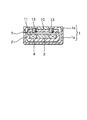
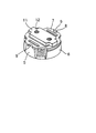
本発明の実施の形態を添付図面に依拠して説明する。図1は、ハウジング1を含む本発明に係る骨伝導スピーカ全体の構成の縦断面図、図2は、ハウジング1内に収納される振動部及び駆動部の分解斜視図、図3は振動部及び駆動部の組立状態図である。
【0013】
ハウジング1は、図1において上下に二分割可能にされ、その容部1aに駆動部が浮上した状態に収納され、その蓋部1bに振動部が固定される。
【0014】
駆動部は、盆状のヨーク2と、ヨーク2の中心に配置されるマグネット3と、マグネット3に巻装されるボイスコイル4とから成る。ヨーク2の周壁は4分割され、その内の対向する2つの立上り部5、5が振動板受けとなり、他の対向する2つの立上り部6、6は磁気回路構成部となる。
【0015】
振動板7を受ける立上り部5、5の上面には、振動板7の両側に形成される切欠き8、8に嵌合する係止突起9、9が突設される。かくして振動板7は、その切欠き8、8内に係止突起9、9を嵌合するようにして上方からヨーク2上に載せることにより、位置決めできると共に、溶接、接着等のスペースを取らない方法で、ヨーク2上に固定することができる。そのために、本発明に係る骨伝導スピーカは、十分に小型化することが可能となるのである。
【0016】
振動板7は、円板の4個所にくびれを設けて四方に突出させた形状を呈し、その対向する2つの突出部に上記切欠き8、8が形成され、また、中央部に大きな長方形状の開口10が形成される。
【0017】
11はプレートヨークで、中央開口10に沿って延び、その両端部が、振動板7の切欠き8、8を設けてない突出部間に載せられて、そこに、溶着、接着等の手段によって固定される。これにより、ヨーク2、マグネット3及びボイスコイル4から成る駆動部と、振動板7及びプレートヨーク11から成る振動部とが一体化される(図3参照)。
【0018】
プレートヨーク11には、通例2個のタップ12、12が形成され、そこに、ハウジング1の蓋部1bを通して固定ネジ13、13がネジ込まれる。かくして、一体化された振動部と駆動部とが、容部1aの内底面から浮上して蓋部1bに吊持された状態にてハウジング1内に組み込まれる(図1参照)。
【0019】
かかる構成において、駆動部に音声又はオーディオ入力信号が供給されると、振動部に振動が発生し、この振動がハウジング1に有効に伝達されることにより、効率のよい骨伝導スピーカが実現される。
【0020】
上述した本発明の実施形態はあくまで一例を示すものであって、本発明はこれに限定されるものではないこと勿論であり、例えば、振動板7の軽量化のために適宜肉抜き部14を設けたり、プレートヨーク11を1本の固定ネジ13で蓋部1bに固定することとしたり、切欠き8と係止突起9の形状を任意のものとしたりすることが可能である。
【0021】
また、切欠き8と係止突起9を設ける代わりに、振動板7の裏面に凸部を設け、立上り部5、5の上面にこの凸部に対応する凹部を設け、その凸部と凹部とを嵌合することも考えられる。
【0022】
【発明の効果】
本発明は上述した通りであって、本発明に係る骨伝導スピーカによれば、ヨーク周縁の立上り部上面と振動板とに設けた係止手段を介して振動板を立上り部上面に固定することとし、また、マグネットをヨークの中心に配置することによって立上り部を薄手に構成可能にすることにより、全体的に小径化することができ、携帯電話等への組み込み等のための小型化の要請に十分に応えることができ、しかも、ボイスコイルの巻数も十分に確保できるため、効率を落とすこともなく、更に、製造が容易でコストの低廉化をも図り得る効果がある。
【図面の簡単な説明】
【図1】本発明に係る骨伝導スピーカの全体構成を示す縦断面図である。
【図2】本発明に係る骨伝導スピーカの振動部と駆動部の分解斜視図である。
【図3】本発明に係る骨伝導スピーカの振動部と駆動部の組立図である。
【図4】従来の骨伝導スピーカの構成図である。
【図5】従来の骨伝導スピーカの他の構成図である。
【図6】従来の骨伝導スピーカの更に他の構成図である。
【符号の説明】
1 ハウジング
1b 蓋部
2 ヨーク
3 マグネット
4 ボイスコイル
5 立上り部
6 立上り部
7 振動板
8 切欠き
9 係止突起
10 開口
11 プレートヨーク
12 タップ
13 固定ネジ
14 肉抜き部[0001]
BACKGROUND OF THE INVENTION
The present invention relates to a bone conduction speaker, and more particularly, to a speaker of a type in which sound is heard by being brought into contact with a head and transmitting vibrations of a diaphragm to bone tissue.
[0002]
[Prior art]
As a conventional bone conduction speaker, a speaker as shown in FIG. 4 is known. It includes a
[0003]
In the case of this bone conduction speaker, the central
[0004]
As described above, a
[0005]
Thus, according to the outer-magnet type bone conduction speaker in which the magnet is arranged on the outer peripheral portion, the
[0006]
Recently, there has been a demand for further downsizing due to the expansion of applications such as incorporating a bone conduction speaker into a mobile phone. However, in the case of this outer-magnet-type bone conduction speaker, the magnet is disposed on the outer periphery, and since a thin magnet is difficult to manufacture due to strength and cost problems, the magnet itself must be of a certain size. Therefore, even if this outer-magnet-type bone conduction speaker is said to be downsized, there is a restriction due to the size of the magnet, and it cannot fully meet the above-mentioned demand for further downsizing.
[0007]
Further, as shown in FIG. 6, the
[0008]
However, in the case of this inner-magnet-type bone conduction speaker, since the upper surface of the
[0009]
[Problems to be solved by the invention]
As described above, none of the various types of bone conduction speakers in the prior art has been able to meet the demand for miniaturization from the viewpoint of incorporation into a mobile phone, and the present invention is intended to meet such a demand. Another object of the present invention is to provide a bone conduction speaker that can be made smaller than conventional ones without reducing efficiency, that is simple to manufacture, and that can be reduced in cost.
[0010]
[Means for Solving the Problems]
A bone conduction speaker according to the present invention for solving the above-mentioned problem is that a magnet is fixed at the center of the yoke, a voice coil is wound around the magnet, the periphery of the yoke is divided, and the rising portion is A locking means is provided on the upper surface of two rising parts facing each other, and a diaphragm provided with a locking means corresponding to the locking means is placed on the rising part and the locking means is interposed therebetween. The diaphragm is attached to the lid portion of the housing in a state where the yoke floats in the housing.
[0011]
Preferably, the locking means provided on the upper surface of the rising portion is a locking protrusion, and the locking means provided on the diaphragm is a notch into which the locking protrusion is fitted.
[0012]
DETAILED DESCRIPTION OF THE INVENTION
Embodiments of the present invention will be described with reference to the accompanying drawings. FIG. 1 is a longitudinal sectional view of the entire structure of a bone conduction speaker according to the present invention including a
[0013]
The
[0014]
The drive unit includes a tray-
[0015]
On the upper surfaces of the rising
[0016]
The
[0017]
[0018]
Two
[0019]
In such a configuration, when an audio or audio input signal is supplied to the drive unit, vibration is generated in the vibration unit, and this vibration is effectively transmitted to the
[0020]
The embodiment of the present invention described above is merely an example, and the present invention is of course not limited to this. For example, the lightening
[0021]
Further, instead of providing the
[0022]
【The invention's effect】
The present invention is as described above, and according to the bone conduction speaker of the present invention, the diaphragm is fixed to the upper surface of the rising portion through the locking means provided on the upper surface of the rising portion and the vibration plate at the periphery of the yoke. In addition, by arranging the magnet in the center of the yoke to make the rising part thin, the overall diameter can be reduced, and there is a demand for downsizing for incorporation into mobile phones, etc. In addition, since the number of turns of the voice coil can be sufficiently secured, there is an effect that the efficiency is not lowered and the manufacturing is easy and the cost can be reduced.
[Brief description of the drawings]
FIG. 1 is a longitudinal sectional view showing an overall configuration of a bone conduction speaker according to the present invention.
FIG. 2 is an exploded perspective view of a vibration part and a drive part of a bone conduction speaker according to the present invention.
FIG. 3 is an assembly diagram of a vibration part and a drive part of a bone conduction speaker according to the present invention.
FIG. 4 is a configuration diagram of a conventional bone conduction speaker.
FIG. 5 is another configuration diagram of a conventional bone conduction speaker.
FIG. 6 is still another configuration diagram of a conventional bone conduction speaker.
[Explanation of symbols]
DESCRIPTION OF
Claims (4)
Priority Applications (8)
| Application Number | Priority Date | Filing Date | Title |
|---|---|---|---|
| JP2002153245A JP3794986B2 (en) | 2002-05-28 | 2002-05-28 | Bone conduction speaker |
| KR10-2004-7019160A KR20050010838A (en) | 2002-05-28 | 2003-05-27 | Bone conductive speaker |
| CN03812025A CN100592821C (en) | 2002-05-28 | 2003-05-27 | Bone conductive speaker |
| EP03730637A EP1515580A1 (en) | 2002-05-28 | 2003-05-27 | Bone conductive speaker |
| CA002487391A CA2487391A1 (en) | 2002-05-28 | 2003-05-27 | Bone conductive speaker |
| AU2003241798A AU2003241798B2 (en) | 2002-05-28 | 2003-05-27 | Bone conductive speaker |
| PCT/JP2003/006594 WO2003101146A1 (en) | 2002-05-28 | 2003-05-27 | Bone conductive speaker |
| US10/515,842 US7292695B2 (en) | 2002-05-28 | 2003-05-27 | Bone conductive speaker |
Applications Claiming Priority (1)
| Application Number | Priority Date | Filing Date | Title |
|---|---|---|---|
| JP2002153245A JP3794986B2 (en) | 2002-05-28 | 2002-05-28 | Bone conduction speaker |
Publications (2)
| Publication Number | Publication Date |
|---|---|
| JP2003340370A JP2003340370A (en) | 2003-12-02 |
| JP3794986B2 true JP3794986B2 (en) | 2006-07-12 |
Family
ID=29561294
Family Applications (1)
| Application Number | Title | Priority Date | Filing Date |
|---|---|---|---|
| JP2002153245A Expired - Fee Related JP3794986B2 (en) | 2002-05-28 | 2002-05-28 | Bone conduction speaker |
Country Status (8)
| Country | Link |
|---|---|
| US (1) | US7292695B2 (en) |
| EP (1) | EP1515580A1 (en) |
| JP (1) | JP3794986B2 (en) |
| KR (1) | KR20050010838A (en) |
| CN (1) | CN100592821C (en) |
| AU (1) | AU2003241798B2 (en) |
| CA (1) | CA2487391A1 (en) |
| WO (1) | WO2003101146A1 (en) |
Families Citing this family (39)
| Publication number | Priority date | Publication date | Assignee | Title |
|---|---|---|---|---|
| US7922321B2 (en) | 2003-10-09 | 2011-04-12 | Ipventure, Inc. | Eyewear supporting after-market electrical components |
| US8465151B2 (en) * | 2003-04-15 | 2013-06-18 | Ipventure, Inc. | Eyewear with multi-part temple for supporting one or more electrical components |
| US8109629B2 (en) | 2003-10-09 | 2012-02-07 | Ipventure, Inc. | Eyewear supporting electrical components and apparatus therefor |
| US7500746B1 (en) | 2004-04-15 | 2009-03-10 | Ip Venture, Inc. | Eyewear with radiation detection system |
| US11513371B2 (en) | 2003-10-09 | 2022-11-29 | Ingeniospec, Llc | Eyewear with printed circuit board supporting messages |
| US10310296B2 (en) | 2003-10-09 | 2019-06-04 | Ingeniospec, Llc | Eyewear with printed circuit board |
| US10345625B2 (en) | 2003-10-09 | 2019-07-09 | Ingeniospec, Llc | Eyewear with touch-sensitive input surface |
| US11630331B2 (en) | 2003-10-09 | 2023-04-18 | Ingeniospec, Llc | Eyewear with touch-sensitive input surface |
| TW200539664A (en) * | 2004-01-16 | 2005-12-01 | Temco Japan | Portable telephone using bone conduction device |
| AU2005212989A1 (en) * | 2004-02-13 | 2005-08-25 | Temco Japan Co., Ltd. | Bone-conduction device and method of manufacturing the same |
| JP4118863B2 (en) * | 2004-06-18 | 2008-07-16 | 株式会社テムコジャパン | Bone conduction device and diaphragm thereof |
| US11829518B1 (en) | 2004-07-28 | 2023-11-28 | Ingeniospec, Llc | Head-worn device with connection region |
| US11644693B2 (en) | 2004-07-28 | 2023-05-09 | Ingeniospec, Llc | Wearable audio system supporting enhanced hearing support |
| JP4419758B2 (en) | 2004-08-31 | 2010-02-24 | 株式会社デンソー | Automotive user hospitality system |
| US11852901B2 (en) | 2004-10-12 | 2023-12-26 | Ingeniospec, Llc | Wireless headset supporting messages and hearing enhancement |
| EP1816829A4 (en) * | 2004-12-02 | 2009-09-09 | Panasonic Corp | Portable terminal apparatus |
| EP1674165A1 (en) * | 2004-12-22 | 2006-06-28 | ETA SA Manufacture Horlogère Suisse | Vibrating device having means for protection against mechanical shocks for a portable device |
| JP4687415B2 (en) * | 2005-09-08 | 2011-05-25 | ゴールデンダンス株式会社 | Bone conduction speaker |
| KR100635833B1 (en) | 2005-09-13 | 2006-10-23 | 이동원 | Bone conductive speaker |
| US11733549B2 (en) | 2005-10-11 | 2023-08-22 | Ingeniospec, Llc | Eyewear having removable temples that support electrical components |
| WO2007095323A2 (en) * | 2006-02-13 | 2007-08-23 | Capper David G | Efficient production of mechanical sound vibration |
| JP2007251281A (en) * | 2006-03-13 | 2007-09-27 | Pioneer Electronic Corp | Speaker |
| SE0600843L (en) | 2006-04-12 | 2007-10-13 | Osseofon Ab | Method of manufacturing balanced vibrator |
| KR100799428B1 (en) | 2006-06-23 | 2008-01-29 | 박의봉 | Bone conductive speaker |
| CN101203067B (en) * | 2007-12-10 | 2012-11-21 | 陈奚平 | Vibration transducer |
| KR100872762B1 (en) * | 2008-03-04 | 2008-12-09 | 팜쉬주식회사 | Voice coil stucture for bone conduction speaker and bone conduction speaker |
| CN101674518B (en) * | 2009-09-22 | 2012-11-21 | 陕西烽火宏声科技有限责任公司 | Electromagnetic type bone conduction telephone receiver |
| WO2012083551A1 (en) * | 2010-12-24 | 2012-06-28 | Jin Zaishan | Bone conduction earphone |
| US9405135B2 (en) | 2011-09-15 | 2016-08-02 | Ipventure, Inc. | Shutter eyewear |
| US10624790B2 (en) | 2011-09-15 | 2020-04-21 | Ipventure, Inc. | Electronic eyewear therapy |
| CN102497610B (en) * | 2011-12-23 | 2013-03-20 | 深圳市韶音科技有限公司 | Vibration conduction sheet device of bone conduction loudspeaker |
| US9288591B1 (en) * | 2012-03-14 | 2016-03-15 | Google Inc. | Bone-conduction anvil and diaphragm |
| US10042186B2 (en) | 2013-03-15 | 2018-08-07 | Ipventure, Inc. | Electronic eyewear and display |
| ITMI20131797A1 (en) * | 2013-10-29 | 2015-04-30 | Buhel S R L | ELECTROMAGNETIC TRANSDUCER TO GENERATE VIBRATIONS FOR BONE CONDUCTION OF SOUNDS AND / OR WORDS |
| WO2015088909A1 (en) * | 2013-12-09 | 2015-06-18 | Etymotic Research, Inc. | System for providing an applied force indication |
| EP3326725B1 (en) * | 2015-07-24 | 2020-07-08 | Alps Alpine Co., Ltd. | Vibration-generating device and operation feel-imparting input device using said vibration-generating device |
| CN105834085A (en) * | 2016-03-18 | 2016-08-10 | 昆山联滔电子有限公司 | Piezoelectric vibrator |
| MX2020004256A (en) * | 2017-10-25 | 2020-09-25 | Ps Audio Design Oy | Transducer arrangement. |
| US10777048B2 (en) | 2018-04-12 | 2020-09-15 | Ipventure, Inc. | Methods and apparatus regarding electronic eyewear applicable for seniors |
Family Cites Families (10)
| Publication number | Priority date | Publication date | Assignee | Title |
|---|---|---|---|---|
| US2062372A (en) * | 1933-08-11 | 1936-12-01 | Sonotone Corp | Bone conduction hearing aid |
| BE406162A (en) * | 1933-11-11 | 1900-01-01 | Sonotone Corp | |
| US2463786A (en) * | 1947-02-10 | 1949-03-08 | E A Myers & Sons | Electromagnetic mechanism for bone conduction receivers, etc. |
| JPS5936479B2 (en) * | 1978-08-21 | 1984-09-04 | スタ−精密株式会社 | Electromagnetic acoustic transducer |
| JPS6167400A (en) * | 1984-09-11 | 1986-04-07 | Sanden Corp | Electromechanical vibration transducer |
| JPH06167400A (en) * | 1992-12-01 | 1994-06-14 | Murata Mfg Co Ltd | Mechanical quantity sensor |
| JP2967777B1 (en) * | 1998-06-08 | 1999-10-25 | 株式会社テムコジャパン | Bone conduction speaker |
| JP2001204096A (en) * | 2000-01-24 | 2001-07-27 | Star Micronics Co Ltd | Electromagnetic acoustic transducer and its manufacturing method |
| KR100344091B1 (en) * | 2000-04-18 | 2002-07-24 | 주식회사 도우미텍 | Arousing bone vibrator and speaker headset for arousing bone using the same |
| JP3556168B2 (en) * | 2000-12-27 | 2004-08-18 | 株式会社テムコジャパン | Bone conduction speaker |
-
2002
- 2002-05-28 JP JP2002153245A patent/JP3794986B2/en not_active Expired - Fee Related
-
2003
- 2003-05-27 CN CN03812025A patent/CN100592821C/en not_active Expired - Fee Related
- 2003-05-27 US US10/515,842 patent/US7292695B2/en not_active Expired - Fee Related
- 2003-05-27 EP EP03730637A patent/EP1515580A1/en not_active Withdrawn
- 2003-05-27 KR KR10-2004-7019160A patent/KR20050010838A/en active IP Right Grant
- 2003-05-27 CA CA002487391A patent/CA2487391A1/en not_active Abandoned
- 2003-05-27 WO PCT/JP2003/006594 patent/WO2003101146A1/en active Application Filing
- 2003-05-27 AU AU2003241798A patent/AU2003241798B2/en not_active Ceased
Also Published As
| Publication number | Publication date |
|---|---|
| KR20050010838A (en) | 2005-01-28 |
| JP2003340370A (en) | 2003-12-02 |
| WO2003101146A1 (en) | 2003-12-04 |
| US7292695B2 (en) | 2007-11-06 |
| EP1515580A1 (en) | 2005-03-16 |
| AU2003241798A1 (en) | 2003-12-12 |
| CN1656849A (en) | 2005-08-17 |
| AU2003241798B2 (en) | 2007-09-13 |
| US20050254672A1 (en) | 2005-11-17 |
| CA2487391A1 (en) | 2003-12-04 |
| CN100592821C (en) | 2010-02-24 |
Similar Documents
| Publication | Publication Date | Title |
|---|---|---|
| JP3794986B2 (en) | Bone conduction speaker | |
| US11240605B2 (en) | Sounding device | |
| US7436088B2 (en) | Electromagnetic exciter | |
| US8379905B2 (en) | Micro-speaker | |
| JP2967777B1 (en) | Bone conduction speaker | |
| JP4867031B2 (en) | Multi-function vibration actuator | |
| US20030123692A1 (en) | Speaker | |
| US20070160238A1 (en) | Bone conduction device | |
| KR100902895B1 (en) | Speaker | |
| WO2010073837A1 (en) | Speaker unit and portable information terminal | |
| US20140056446A1 (en) | Micro-Speaker | |
| EP1151632A1 (en) | Vibration exciter for creating bending wave vibration | |
| CN101330987B (en) | Thin multi-function vibration actuator | |
| KR20020003169A (en) | Receiving unit for mobile communication terminal | |
| US20230328443A1 (en) | Multifunctional Sounding Device | |
| JP2005323054A (en) | Bone conduction speaker | |
| JP5076237B2 (en) | Magnetic circuit structure of multifunctional vibration actuator | |
| JP2008092560A (en) | Electroacoustic transducer | |
| JP2008147732A (en) | Bone conduction speaker | |
| KR20080055571A (en) | Multi-functional microspeaker | |
| JP2006311156A (en) | Electroacoustic transducer | |
| KR200359898Y1 (en) | Two way speaker | |
| KR20080054323A (en) | Multi-function microspeaker | |
| CN219876071U (en) | Micro-speaker and audio device | |
| JP2003102092A (en) | Electroacoustic transducer |
Legal Events
| Date | Code | Title | Description |
|---|---|---|---|
| A131 | Notification of reasons for refusal |
Free format text: JAPANESE INTERMEDIATE CODE: A131 Effective date: 20060117 |
|
| TRDD | Decision of grant or rejection written | ||
| A01 | Written decision to grant a patent or to grant a registration (utility model) |
Free format text: JAPANESE INTERMEDIATE CODE: A01 Effective date: 20060406 |
|
| A61 | First payment of annual fees (during grant procedure) |
Free format text: JAPANESE INTERMEDIATE CODE: A61 Effective date: 20060411 |
|
| R150 | Certificate of patent or registration of utility model |
Free format text: JAPANESE INTERMEDIATE CODE: R150 |
|
| FPAY | Renewal fee payment (event date is renewal date of database) |
Free format text: PAYMENT UNTIL: 20100421 Year of fee payment: 4 |
|
| LAPS | Cancellation because of no payment of annual fees |