JP3787140B2 - Wall structure - Google Patents
Wall structure Download PDFInfo
- Publication number
- JP3787140B2 JP3787140B2 JP2004062423A JP2004062423A JP3787140B2 JP 3787140 B2 JP3787140 B2 JP 3787140B2 JP 2004062423 A JP2004062423 A JP 2004062423A JP 2004062423 A JP2004062423 A JP 2004062423A JP 3787140 B2 JP3787140 B2 JP 3787140B2
- Authority
- JP
- Japan
- Prior art keywords
- plate body
- plate
- support plates
- side edges
- column
- Prior art date
- Legal status (The legal status is an assumption and is not a legal conclusion. Google has not performed a legal analysis and makes no representation as to the accuracy of the status listed.)
- Expired - Lifetime
Links
- 239000000463 material Substances 0.000 description 11
- 238000000034 method Methods 0.000 description 8
- 238000010008 shearing Methods 0.000 description 7
- 238000004891 communication Methods 0.000 description 3
- 230000006835 compression Effects 0.000 description 3
- 238000007906 compression Methods 0.000 description 3
- 230000000149 penetrating effect Effects 0.000 description 3
- 239000011120 plywood Substances 0.000 description 3
- NJPPVKZQTLUDBO-UHFFFAOYSA-N novaluron Chemical compound C1=C(Cl)C(OC(F)(F)C(OC(F)(F)F)F)=CC=C1NC(=O)NC(=O)C1=C(F)C=CC=C1F NJPPVKZQTLUDBO-UHFFFAOYSA-N 0.000 description 2
- 229910000831 Steel Inorganic materials 0.000 description 1
- 238000003780 insertion Methods 0.000 description 1
- 230000037431 insertion Effects 0.000 description 1
- 238000006116 polymerization reaction Methods 0.000 description 1
- 230000003014 reinforcing effect Effects 0.000 description 1
- 239000012779 reinforcing material Substances 0.000 description 1
- 239000010959 steel Substances 0.000 description 1
- 239000002023 wood Substances 0.000 description 1
Images


Description
本発明は、木造住宅などの建築物における壁体の構造に関するものである。 The present invention relates to a wall structure in a building such as a wooden house.
木造住宅などの建築物の構造としては、一般に、土台と梁などの横架材とこれら横架材の間に挟まれて立設される鉛直材である柱とで大略構成され、横架材と柱とは、柱の柱脚・柱頭に各種接合具を用いて互いを緊結固定している。 The structure of a building such as a wooden house is generally composed of horizontal members such as foundations and beams, and pillars that are vertical members placed between these horizontal members. The column and the column are tightly fixed to each other using various joints on the column base and head of the column.
この接合具としては、従来より各種構造のものがあり、柱側面に接合金物を設置し横架材と接合金物をボルトにて接合する構成である所謂ホールダウン金物や、ほぞパイプ型の接合金物にて柱脚・柱頭を接合する構成(下記特許文献1)、鋼板を互いに挿入状態として接合する構成(下記特許文献2)などがある。
しかしながら、上述した従来の各種接合具は、横架材と柱との接合であり、構築物として構成された際の耐せん断力、特に上下横架材間の引張に対する強度を得られる部材となっている。すなわち、上述の各種接合具を備えることで、上下横架材と左右の柱とで組み合わされる枠状の構成として構造耐力を考えた場合に、上下の横架材の間隔距離が拡がるような外力となるせん断力が加わった場合にはこれら接合具によってその外力、すなわち横架材に対する柱の引抜き力に耐えられるようになっている。また、上下の横架材の間で狭まるような外力の場合には両横架材間に挟まるように配置される柱自体の耐座屈強度で耐えるようになっている。 However, the above-mentioned various conventional joints are joints between horizontal members and columns, and are members that can obtain shear resistance when constructed as a structure, particularly strength against tension between upper and lower horizontal members. Yes. That is, by providing the above-mentioned various connectors, an external force that increases the distance between the upper and lower horizontal members when the structural strength is considered as a frame-like configuration combined with the upper and lower horizontal members and the left and right columns. When a shearing force is applied, these joints can withstand the external force, that is, the pulling force of the column on the horizontal member. Further, in the case of an external force that is narrowed between the upper and lower horizontal members, the column is arranged so as to withstand the buckling strength of the pillars arranged so as to be sandwiched between the horizontal members.
そして、これら外力に対する耐力増強を図るために、上記した上下の横架材と柱とによる枠状の構成に、筋交いなどの斜材を補強材として設け、また間柱を設けてさらに合板など面材を外側から釘やビスで打ち付け壁体として構成しており、すなわち、壁体を構成するために、梁や土台などの横架材と、柱とを各種接合金物にて固定するとともに、筋交いを固定し、合板を多数のビスや釘等の接合部材を用いて二辺、三辺、川の字形或いは四周を各柱或いは各柱と横架材に固定している。 In order to increase the proof strength against these external forces, the above-described frame structure composed of the upper and lower horizontal members and pillars is provided with diagonal materials such as braces as reinforcing materials, and further provided with inter-columns and further face materials such as plywood. In order to construct the wall body, the horizontal members such as beams and foundations and the columns are fixed with various joint hardware, and the bracing is performed. The plywood is fixed to each column or each column and a horizontal member by using a large number of joining members such as screws and nails.
このように構成される壁体によれば、外力が加わると、梁,柱,土台などの構造部材にまず伝達して、その後、ビス、釘を介して面材に伝達させることでせん断耐力が得られるようになっている。言い換えれば、面材には回転力が発生し、この回転を釘やビスに伝達し、その後、柱に持ち上がりの力(引抜き力)が作用することで、土台・梁より柱が抜けてしまうおそれがある。そして、この壁体が、せん断力を耐えるにあたり、柱が梁や土台から引き抜けないように柱脚及び柱頭に上記した接合金物を用いて、柱を土台や梁に固定する必要があり、すなわち、壁体の構造として、十分な耐力を得るために多くの部材を組み合わせる必要があった。 According to the wall configured as described above, when an external force is applied, the shear strength is first transmitted to structural members such as beams, columns, and foundations, and then transmitted to the face material via screws and nails. It has come to be obtained. In other words, a rotational force is generated in the face material, and this rotation is transmitted to the nail or screw, and then the lifting force (pull-out force) acts on the column, which may cause the column to come off from the base / beam. There is. And when this wall body bears a shearing force, it is necessary to fix the column to the base or beam using the above-mentioned joint hardware to the column base and the head so that the column does not pull out from the beam or the base. As a structure of the wall body, it is necessary to combine many members in order to obtain sufficient strength.
そこで本発明は、上記問題点を解消するために、柱と梁や土台との接合部分、すなわち柱脚・柱頭部分や、その他の部分において、接合金物等の接合具を多用することなく、好ましくは必要最小限とし、壁体として構成した際に十分な剛性を得ることができ、せん断力等の外力に対する耐久力を有した壁体の構造を提供することを目的としている。 Therefore, in order to solve the above-mentioned problems, the present invention is preferably used without frequently using a joining tool such as a joint hardware in a joint portion between a column and a beam or a base, that is, a column base, a head portion, or other portions. The object of the present invention is to provide a structure of a wall body that can obtain sufficient rigidity when it is configured as a wall body and has durability against an external force such as a shearing force.
次に、上記の課題を解決するための手段を、実施の形態に対応する図面を参照して説明する。
この発明の請求項1記載の壁体の構造は、一枚板よりなり、壁体の一部を構成する板体3と、
該板体3の左右各側縁3a,3bにおける表裏両面に、該側縁3a,3bに沿って展設される帯板状の支持板5,6と、
前記板体3の上下各縁部3c,3dと、前記各支持板5,6の上下各端部5a,6a,5b,6bとが嵌入するスリット状の係合凹部10,12を備えた上下一対の横架材9,11と、
前記板体3の左右各側縁3a,3bと、該側縁3a,3bの表裏両面に位置する前記各支持板5,6の側縁が嵌入する凹溝15,17を有するとともに、前記上下横架材9,11の間に立設される柱部材14,16と、
前記横架材9,11外側面から前記板体3の四隅に位置して打設されて、前記係合凹部10,12内にて前記板体3と該板体3の表裏両面に配置される前記支持板5,6とを貫通し固定する線状固定部材23と、
を具備することを特徴とする。
Next, means for solving the above problems will be described with reference to the drawings corresponding to the embodiments.
The structure of the wall body according to
Band-plate-
Upper and lower sides provided with slit-like
The
It is placed at the four corners of the
It is characterized by comprising.
この壁体の構造によれば、板体3の上下縁部3a,3bにおける隅部分、すなわち板体3の四隅となる位置を上下の横架材9,11にそれぞれ線状固定部材23にて固定される。この固定状態では、板体3の上縁部3cと支持板5,6の上端5a,6a、板体3の下縁部3dと支持板5,6の下端5b,6がそれぞれ重合したまま線状固定部材23が貫通して固定となる。また、柱部材14,16は、その上下の横架材9,11間を支えるような構成とされて壁体が構成される。
According to this wall structure, the corner portions of the upper and
請求項2記載の壁体の構造は、一枚板よりなり、壁体の一部を構成する板体3と、
該板体3の左右各側縁3a,3bにおける表裏両面に、該側縁3a,3bに沿って展設される帯板状の支持板5,6と、
前記板体3の上下各縁部3c,3dと、前記各支持板5,6の上下各端部5a,6a,5b,6bとが嵌入するスリット状の係合凹部10,12を備えた上下一対の横架材9,11と、
前記板体3の左右各側縁3a,3bと、該側縁3a,3bの表裏両面に位置する前記各支持板5,6の側縁が嵌入する凹溝15,17を有するとともに、前記上下横架材9,11の間に立設される柱部材14,16と、
該柱部材14,16の外側面から前記凹溝15,17内にて前記支持板5,6と前記板体3とを貫通し、これら支持板5,6と板体3と柱部材14,16とを固定する線状固定材22と、
前記横架材9,11外側面から前記板体3の四隅に位置して打設されて、前記係合凹部10,12内にて前記板体3と該板体3の表裏両面に配置される前記支持板5,6とを貫通し固定する線状固定部材23と、
を具備することを特徴とする。
The structure of the wall according to claim 2 is composed of a single plate, and a
Band-plate-
Upper and lower sides provided with slit-like
The
The
It is placed at the four corners of the
It is characterized by comprising.
この壁体の構造によれば、板体3の上下縁部3c,3dにおける隅部分、すなわち板体3の四隅となる位置を上下の横架材9,11にそれぞれ線状固定部材23にて固定される。この固定状態では、板体3の上縁部3cと支持板5,6の上端5a,6a、板体3の下縁部3dと支持板5,6の下端5b,6bがそれぞれ重合したまま線状固定部材23が貫通して固定となる。また、柱部材14,16は、その上下の横架材9,11間を支えるような構成とされて壁体が構成される。また、左右各支持板5,6と板体3とを貫通し、かつ各柱部材14,16を貫通して線状固定材22、例えばボルトなどが設けられる。
According to this wall structure, the corner portions of the upper and
以上説明したように本発明による壁体の構造では、板体の上下縁部における隅部分を上下の横架材にそれぞれ固定して、柱部材は、その上下の横架材間を支えるような構成とされて壁体を構成しており、せん断力が発生した場合には、このせん断力を板体に伝達させるようになっており、従来のような梁や土台など横架材から柱が引き抜かれてしまうことで壁体全体が損壊するようなことがない。特に柱部材は横架材に固定されずに、耐圧縮力のみを負担する。そして、上下横架材間が拡がるような外力に対しては、上下の横架材に、線状固定部材にて板体と支持板とが固定されており、これら板体と支持板とがその上下端を固定されることで耐力が得られるようになっている。 As described above, in the wall structure according to the present invention, the corner portions of the upper and lower edges of the plate are fixed to the upper and lower horizontal members, and the column member supports the upper and lower horizontal members. When a shearing force is generated, the shearing force is transmitted to the plate, and the pillars are made from horizontal materials such as conventional beams and foundations. The entire wall body is not damaged by being pulled out. In particular, the column member is not fixed to the horizontal member and bears only the compression resistance. And for external force that spreads between the upper and lower horizontal members, the plate and the support plate are fixed to the upper and lower horizontal members by a linear fixing member, and these plate and support plate are The strength is obtained by fixing the upper and lower ends.
また、左右各支持板と板体とを貫通し、かつ各柱部材を貫通して線状固定材、例えばボルトなどが設けられることで、上下横架材間に配置される左右柱部材が脱落してしまうことがなくなる。 In addition, the left and right column members arranged between the upper and lower horizontal members are dropped by penetrating each of the left and right support plates and the plate body and penetrating each column member to provide a linear fixing material such as a bolt. It will not be done.
そして、従来用いられていた柱脚、柱頭部分でのホールダウン金物のような接合金物などを使用なくとも、十分な耐力が得られることから、その接合金物で占有されてしまう柱脚周辺や柱頭周辺、特に隅部分での設計自由度、すなわち、他の補強構造の追加や、意匠性を加味した構造など、用途が拡がることとなる。 And, since it is possible to obtain sufficient strength without using joint bases such as hole-down hardware at the pedestal and stigma used in the past, the periphery of the pedestal and the stigma occupied by the joint hardware Applications such as addition of other reinforcing structures and structures taking design into consideration are expanded, such as design freedom in the periphery, particularly corners.
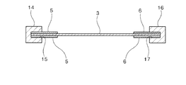
図1は本発明による壁体の構造の実施の形態を示す分解斜視図、図2は同壁体の構造の正面図、図3は図2におけるA−A線断面図である。 FIG. 1 is an exploded perspective view showing an embodiment of a wall structure according to the present invention, FIG. 2 is a front view of the wall structure, and FIG. 3 is a cross-sectional view taken along line AA in FIG.
本発明の壁体の構造1は、板体と、支持板と、横架材と、柱部材と、線状固定材と、線状固定部材とで大略構成されている。
板体3は、木質の一枚板よりなり、例えば合板などで構成され、所定厚さで所定の縦横長さの矩形状に形成されている。本実施の形態では、左右側縁3a,3bに、それぞれ複数箇所、例えば略等間隔に3カ所ずつに貫通穴4が穿設されている。
The
The
支持板5,6は、板体3と略同素材の板材よりなり、所定厚さとされるとともに、上下方向に長尺で板体の縦長さと略同等の長さとされ、所定の幅長で略帯板状に形成されている。この支持板5,6は、板体3の左右各側縁3a,3bにそれぞれ配置されるとともに、板体3の表裏両面にそれぞれ配置されて、すなわち4枚で1組とされる。本実施の形態では、各支持板5,6には、一方の側縁に沿って、上記板体3の貫通穴4の位置と一致する貫通穴7,8が穿設されている。そして、これら支持板5,6は、板体3の表裏面に密着した状態で板体3に対しては接着などの固定は行われずに、左右側縁3a,3bに沿って上下方向に展設される。
The
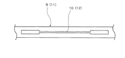
横架材9,11は、所謂土台や梁を構成するもので、上下一対で構成され、それぞれが略水平に互いに略平行となって設置されるものである。これら梁9と土台11とには、スリット状の係合凹部10,12がそれぞれ対向するように形成される。この係合凹部は、図4に示すように、板体3と各支持板5,6とが嵌入可能な形状とされ、すなわち、板体3の断面形状と、この板体3の側縁3a,3bに沿って展設される支持板5,6の断面形状とを合せた形状、図4に示すように、両端部分がやや幅広とされた真直な形状に形成されている。そして、土台11の係合凹部12には、板体3の下縁部3dと左右及び表裏面の各支持板5,6の下端5b,6bが嵌入し、梁9の係合凹部10には、板体3の上縁部3cと左右及び表裏面の各支持板5,6の上端5a,6aが嵌入する。なお、この係合凹部10,11は、梁9及び土台11を貫通して形成されてもよく、或いは有底溝として形成してもよい。
The
柱部材14,16は、横架材である梁9と土台11との間に立設されるもので、左右一対で構成され、断面略矩形の角柱部材よりなるとともに、図1,図3に示すように、互いに対向する側面に凹溝15,17が形成されている。各凹溝15,17は、板体3と、この板体3の両面に展設される各支持板5,6の合計の厚さと略一致する幅長の凹溝15,17とされ、長手方向に連続して形成される。また、柱部材14,16には、凹溝15,17の長手方向に直交する方向で、凹溝15,17を貫通するように取付穴18,19が穿設されている。この取付穴18,19は、上記した板体3と支持板5,6とに穿設される各貫通穴4,7,8に対応しており、長手方向に略等間隔となって複数、本実施の形態では3カ所設けられている。そして、この柱部材14,16の凹溝15,17には、板体3と支持板5,6とが重合した状態で嵌入し、且つ、板体3の貫通穴4と支持板5,6の貫通穴7,8とこの柱部材14,16の取付穴18,19とが連通するようになっている。
The
線状固定材22は、本実施の形態では、ボルト20とナット21とで構成される。ボルト20は、柱部材14,16の取付穴18,19に挿通されるとともに、この柱部材14,16の凹溝15,17に嵌入する板体3及び支持板5,6の貫通穴7,8に挿通される。そして、貫通するボルト20先端の雄ねじ部にナット21が螺着され締結となる。
In the present embodiment, the linear fixing
線状固定部材23は、本実施の形態では、複数の釘やビスなどよりなる。これら釘或いはビス23は、横架材である梁9,土台11の外側面から、板体3の四隅に位置して打設され、係合凹部10,12内にて板体3の隅部分と支持板5,6の端部とを貫通して、それぞれが固定される。
In the present embodiment, the linear fixing
次に、上述した構成の壁体の構造の組み立て手順について説明する。
まず、図5に示すように、板体3の左右側縁3a,3bに、支持板5,6を重ねる。支持板5,6は、4枚で構成され、板体3の左右側縁3a,3bにおける表裏両面に重合状態とされる。このとき、板体3と支持板5,6との各貫通穴4,7,8を連通状態とする。なお、各貫通穴4,7,8が連通状態を維持するように、各板3,5,6をクリップなどの工具や治具を用いて仮保持すると良い。
Next, the assembly procedure of the structure of the wall body having the above-described configuration will be described.
First, as shown in FIG. 5, the
次に、左右柱部材14,16の各凹溝15,17に、図6に示すように、上記重合状態の板体3と支持板5,6の側縁部分を嵌入させる。嵌入する際には、柱部材14,16の各取付穴18,19と、連通状態となっている各貫通穴4,7,8とを一致させそれぞれが連通するように行う。
Next, as shown in FIG. 6, the side edge portions of the
次に、各柱部材14,16のそれぞれの取付穴18,19にボルト20を挿着する。そして、これらボルト20を柱部材14,16とともに板体3と支持板5,6とを貫通させ、ボルト先端の雄ねじ部にナット21を螺着し締結固定する。この締結固定を終えると、板体3の左右側縁3a,3bに、表裏両面に帯板状の支持板5,6が展設された状態となるとともに、左右各側縁3a,3bに柱部材14,16がボルト20・ナット21により取り付けられた状態となる。
Next, the
次に、支持板5,6,柱部材14,16が取り付けられた板体3を立ち上げ、土台11に形成された係合凹部12に板体3の下縁3d及び各支持板5,6の下端5b,6bを嵌入させる。嵌入された状態では、左右柱部材14,16の下端面が土台11の上面に当接状態となる。
Next, the
次に、板体3の上縁3c及び各支持板5,6の上端5a,6aが、梁9の係合凹部10に嵌入するように、この梁9を上方から取り付ける。上縁3cと上端5a,6aとが係合凹部10内に嵌入した状態では、左右柱部材14,16の上端面が梁9の下面に当接状態となる。
この状態で、梁9と土台11との間に、各柱部材14,16が立設配置されることとなる(図7参照)。
Next, the
In this state, the
次に、梁9と土台11の各一方の外側面から、板体3の四隅に位置して、すなわち、係合凹部10,12内にて板体3と板体3の表裏両面に配置される支持板5,6の端部とが重合した位置となる外側面から、これらを貫通するように釘或いはビス23が打ち込まれる。なお、梁9と土台11とには、予め下穴を穿設しておいてもよい。
以上で完成となる。
Next, from the outer side of each one of the
This completes the process.
このように構成された壁体の構造は、横架材である梁9と土台11との間に、柱部材14,16が立設され、これら梁9、土台11、左右柱部材14,16に囲繞されるように板体3が配置される構成であるが、板体3の上縁3aと各支持板5,6の上端5a,6aとが梁9の係合凹部10に嵌入し、また板体3の下縁3bと各支持板5,6の下端5b,6bとが土台11の係合凹部12に嵌入し、そして板体3の左右両側縁3a,3bにおける表裏両面に支持板5,6が重合状態とされ、この重合状態のまま柱部材14,16の凹溝15,17に嵌入されている。柱部材14,16と板体3及び各支持板5,6とは、ボルト20が貫通しナット21で締結固定される。このボルト20・ナット21による固定により、板体3と支持板5,6とに対して柱部材14,16が脱落しないようになる。また釘或いはビス23が梁9と土台11との外側面から複数打設されて、これら梁9と土台11とに板体3と支持板5,6とが固定される。この状態においては、左右の各柱部材14,16は、梁9と土台11との間に配置され、各柱部材14,16の両端である上下端は、これら梁9と土台11とに直接は固定されない。
In the structure of the wall body configured in this way,
したがって、板体3の四隅が、梁9と土台11となる横架材に固定される構造であり、柱部材14,16は固定されず、この柱部材14,16は、耐圧縮力のみ負担することとなる。すなわち、板体3を横架材9,11に固定して、柱14,16は、その上下の横架材9,11間を支えるような構成とされて壁体1を構成しており、せん断力が発生した場合に、このせん断力を板体3に伝達させるようになっており、従来のような梁や土台から柱が引き抜かれてしまうことがない。そして、梁9と土台11との間が拡がるような外力に対しては、梁9と土台間11に、釘或いはビス23にて板体3と支持板5,6とが固定されることで耐力を得ることができる。
Accordingly, the four corners of the
このような壁体の構造によれば、従来のようなホールダウン金物などの接合部材を使用しなくとも、十分な耐力を備えた壁体1を得ることができ、梁9と土台11との間の引張や圧縮などの外力に対して有効な構造を得ることが可能となる。
According to such a structure of the wall body, the
また、この壁体の構造によれば、従来では、板体である面材を取り付けるために多数の釘やビスを用い、各柱や梁、土台などに対して、すなわち板体の周縁に打ち付けるような施行手順であったが、板体3の四隅部分にのみ釘やビス23を打ち付けて固定する手順であるので、作業性が向上するとともに、省力化が得られる。
In addition, according to the structure of the wall body, conventionally, a large number of nails and screws are used to attach the face material that is a plate body, and it is struck against each column, beam, base, or the like, that is, the periphery of the plate body. Although the procedure is such a procedure, it is a procedure in which nails and screws 23 are driven and fixed only at the four corners of the
1…壁体
3…板体
3a…左縁部
3b…右縁部
3c…上端縁
3d…下端縁
5,6…支持板
5a,6a…上端
5b,6b…下端
9…横架材(梁)
10,12…係合凹部
11…横架材(土台)
14,16…柱部材
15,17…凹溝
22…線状固定材
23…線状固定部材
DESCRIPTION OF
10, 12 ... Engaging
DESCRIPTION OF
Claims (2)
該板体の左右各側縁における表裏両面に、該側縁に沿って展設される帯板状の支持板と、
前記板体の上下各縁部と、前記各支持板の上下各端部とが嵌入するスリット状の係合凹部を備えた上下一対の横架材と、
前記板体の左右各側縁と、該側縁の表裏両面に位置する前記各支持板の側縁が嵌入する凹溝を有するとともに、前記上下横架材の間に立設される柱部材と、
前記横架材外側面から前記板体の四隅に位置して打設されて、前記係合凹部内にて前記板体と該板体の表裏両面に配置される前記支持板とを貫通し固定する線状固定部材と、
を具備することを特徴とする壁体の構造。 A plate made of a single plate and constituting a part of the wall,
On both the front and back sides of the left and right side edges of the plate body, a belt-like support plate extended along the side edges,
A pair of upper and lower horizontal members provided with slit-like engaging recesses into which the upper and lower edges of the plate body and the upper and lower ends of each support plate are fitted;
Column members that have left and right side edges of the plate body and concave grooves into which the side edges of the support plates located on the front and back surfaces of the side edges are fitted, and that are erected between the upper and lower horizontal members, ,
Positioned at the four corners of the plate body from the lateral surface of the horizontal member, and penetrates and fixes the plate body and the support plates disposed on the front and back surfaces of the plate body in the engagement recess. A linear fixing member,
The structure of the wall characterized by comprising.
該板体の左右各側縁における表裏両面に、該側縁に沿って展設される帯板状の支持板と、
前記板体の上下各縁部と、前記各支持板の上下各端部とが嵌入するスリット状の係合凹部を備えた上下一対の横架材と、
前記板体の左右各側縁と、該側縁の表裏両面に位置する前記各支持板の側縁が嵌入する凹溝を有するとともに、前記上下横架材の間に立設される柱部材と、
該柱部材の外側面から前記凹溝内にて前記支持板と前記板体とを貫通し、これら支持板と板体と柱部材とを固定する線状固定材と、
前記横架材外側面から前記板体の四隅に位置して打設されて、前記係合凹部内にて前記板体と該板体の表裏両面に配置される前記支持板とを貫通し固定する線状固定部材と、
を具備することを特徴とする壁体の構造。 A plate made of a single plate and constituting a part of the wall,
On both the front and back sides of the left and right side edges of the plate body, a belt-like support plate extended along the side edges,
A pair of upper and lower horizontal members provided with slit-like engaging recesses into which the upper and lower edges of the plate body and the upper and lower ends of each support plate are fitted;
Column members that have left and right side edges of the plate body and concave grooves into which the side edges of the support plates located on the front and back surfaces of the side edges are fitted, and that are erected between the upper and lower horizontal members, ,
A linear fixing member that penetrates the support plate and the plate body in the concave groove from the outer surface of the column member, and fixes the support plate, the plate body, and the column member;
Positioned at the four corners of the plate body from the lateral surface of the horizontal member, and penetrates and fixes the plate body and the support plates disposed on the front and back surfaces of the plate body in the engagement recess. A linear fixing member,
The structure of the wall characterized by comprising.
Priority Applications (1)
| Application Number | Priority Date | Filing Date | Title |
|---|---|---|---|
| JP2004062423A JP3787140B2 (en) | 2004-03-05 | 2004-03-05 | Wall structure |
Applications Claiming Priority (1)
| Application Number | Priority Date | Filing Date | Title |
|---|---|---|---|
| JP2004062423A JP3787140B2 (en) | 2004-03-05 | 2004-03-05 | Wall structure |
Publications (2)
| Publication Number | Publication Date |
|---|---|
| JP2005248615A JP2005248615A (en) | 2005-09-15 |
| JP3787140B2 true JP3787140B2 (en) | 2006-06-21 |
Family
ID=35029357
Family Applications (1)
| Application Number | Title | Priority Date | Filing Date |
|---|---|---|---|
| JP2004062423A Expired - Lifetime JP3787140B2 (en) | 2004-03-05 | 2004-03-05 | Wall structure |
Country Status (1)
| Country | Link |
|---|---|
| JP (1) | JP3787140B2 (en) |
Families Citing this family (3)
| Publication number | Priority date | Publication date | Assignee | Title |
|---|---|---|---|---|
| CN103147527A (en) * | 2013-03-29 | 2013-06-12 | 苏州皇家整体住宅系统股份有限公司 | Plywood shearing wall |
| CN103556756A (en) * | 2013-10-14 | 2014-02-05 | 苏州皇家整体住宅系统股份有限公司 | Interlayer shear wall assembly |
| JP6114870B1 (en) * | 2016-11-04 | 2017-04-12 | 株式会社アクト | Wall panel and its fixing structure |
-
2004
- 2004-03-05 JP JP2004062423A patent/JP3787140B2/en not_active Expired - Lifetime
Also Published As
| Publication number | Publication date |
|---|---|
| JP2005248615A (en) | 2005-09-15 |
Similar Documents
| Publication | Publication Date | Title |
|---|---|---|
| JP3581426B2 (en) | Structural materials and floor and roof structures of wooden buildings and construction methods using them | |
| JP3714902B2 (en) | Column and cross member joining device | |
| JP3787140B2 (en) | Wall structure | |
| JP4625528B2 (en) | Building unit structural member and floor structure using the unit structural member | |
| JP6837826B2 (en) | Building reinforcement structure and reinforcement method | |
| JP3209111U (en) | Vertical frame material and steel house | |
| JP6484752B1 (en) | Load-bearing panel and wooden frame building | |
| JP2807524B2 (en) | Column and beam joint structure | |
| JP7062463B2 (en) | Connection structure | |
| JP4080419B2 (en) | Mounting structure of the joint fitting at the beam-column joint | |
| JP3192439B2 (en) | Joining structure of building components | |
| JP7082099B2 (en) | Building structure | |
| JP2004124698A (en) | Building structure and wall panel | |
| JP6994281B1 (en) | Shafted panel members, wall panels and beam structures | |
| JP4100363B2 (en) | Composite member, member joining structure and joining method | |
| JP2013241803A (en) | Force bearing wall | |
| JP5650383B2 (en) | Multistage braided joint shaft | |
| JP6972803B2 (en) | Construction method of joint structure and surface structure | |
| JP4934423B2 (en) | Composite member and building structure using the same | |
| JP2024035049A (en) | Joint structure between horizontal members | |
| JP2725165B2 (en) | Joining structure of wooden building horizontal members and its tools | |
| JP2006104774A (en) | Building member connection structure | |
| JP2019196656A (en) | Junction structure of structural skeleton of wooden building and wooden building | |
| JP6564606B2 (en) | Wooden / Steel Laminated Beam Structure | |
| JP2001234584A (en) | Jointed construction of wall column and floor beam using veneer laminated member |
Legal Events
| Date | Code | Title | Description |
|---|---|---|---|
| A977 | Report on retrieval |
Free format text: JAPANESE INTERMEDIATE CODE: A971007 Effective date: 20060228 |
|
| TRDD | Decision of grant or rejection written | ||
| A01 | Written decision to grant a patent or to grant a registration (utility model) |
Free format text: JAPANESE INTERMEDIATE CODE: A01 Effective date: 20060307 |
|
| A61 | First payment of annual fees (during grant procedure) |
Free format text: JAPANESE INTERMEDIATE CODE: A61 Effective date: 20060323 |
|
| R150 | Certificate of patent or registration of utility model |
Ref document number: 3787140 Country of ref document: JP Free format text: JAPANESE INTERMEDIATE CODE: R150 Free format text: JAPANESE INTERMEDIATE CODE: R150 |
|
| FPAY | Renewal fee payment (event date is renewal date of database) |
Free format text: PAYMENT UNTIL: 20120331 Year of fee payment: 6 |
|
| R250 | Receipt of annual fees |
Free format text: JAPANESE INTERMEDIATE CODE: R250 |
|
| FPAY | Renewal fee payment (event date is renewal date of database) |
Free format text: PAYMENT UNTIL: 20120331 Year of fee payment: 6 |
|
| FPAY | Renewal fee payment (event date is renewal date of database) |
Free format text: PAYMENT UNTIL: 20150331 Year of fee payment: 9 |
|
| R250 | Receipt of annual fees |
Free format text: JAPANESE INTERMEDIATE CODE: R250 |
|
| R250 | Receipt of annual fees |
Free format text: JAPANESE INTERMEDIATE CODE: R250 |
|
| R250 | Receipt of annual fees |
Free format text: JAPANESE INTERMEDIATE CODE: R250 |
|
| R250 | Receipt of annual fees |
Free format text: JAPANESE INTERMEDIATE CODE: R250 |
|
| R250 | Receipt of annual fees |
Free format text: JAPANESE INTERMEDIATE CODE: R250 |
|
| R250 | Receipt of annual fees |
Free format text: JAPANESE INTERMEDIATE CODE: R250 |