JP3785669B2 - Gaze direction measuring device - Google Patents
Gaze direction measuring device Download PDFInfo
- Publication number
- JP3785669B2 JP3785669B2 JP04761896A JP4761896A JP3785669B2 JP 3785669 B2 JP3785669 B2 JP 3785669B2 JP 04761896 A JP04761896 A JP 04761896A JP 4761896 A JP4761896 A JP 4761896A JP 3785669 B2 JP3785669 B2 JP 3785669B2
- Authority
- JP
- Japan
- Prior art keywords
- correction coefficient
- gaze
- eyeball
- unit
- line
- Prior art date
- Legal status (The legal status is an assumption and is not a legal conclusion. Google has not performed a legal analysis and makes no representation as to the accuracy of the status listed.)
- Expired - Fee Related
Links
Images


Landscapes
- Fittings On The Vehicle Exterior For Carrying Loads, And Devices For Holding Or Mounting Articles (AREA)
- Eye Examination Apparatus (AREA)
- Length Measuring Devices With Unspecified Measuring Means (AREA)
Description
【0001】
【発明の属する技術分野】
本発明は、遠隔から視線の方向を計測する装置に関し、特に、計測対象者に応じた補正係数を自動的に算出する視線方向計測装置に関する。
【0002】
【従来の技術】
視線方向計測装置は、ヒューマン・マシンインタフェイスとして、計測した視線方向を用いて例えば車両運転者の注目している方向に視覚情報を表示させたり、視線方向に応じて特定のスイッチを動作させる等、種々の利用が期待されている。一般にこのような視線方向計測装置で計測される視線方向は、計測対象者の個人差に起因する計測誤差を伴う。このため従来の視線方向計測装置では、計測誤差を補正する動作、所謂キャリブレーション動作を行って補正係数を算出し、この補正係数を考慮して視線方向の計測を行うことにより計測誤差の影響を少なくしている。しかし、キャリブレーション動作は装置の使用者(計測対象者)に煩わしい操作を強要することが多く、使用者に意識させずにキャリブレーション動作を完了することが望まれている。
【0003】
使用者に意識させずにキャリブレーション動作を完了するようにした従来の技術としては、例えば、特開平7-151958号公報等で開示されたものがある。この従来の装置では、使用者が装置の操作を行う場合に、特定の操作はその操作に応じた表示を見ながら行われると仮定して、特定の操作が行われるときの視線方向を計測し、この計測した視線の方向がその操作に応じた表示の方向と一致するとして補正係数を求めるものである。
【0004】
【発明が解決しようとする課題】
このような従来の装置では、使用者の眼球は所定の位置に固定されるものとして視線方向が計測される。図20は眼球位置が固定される場合の視線方向を示す。図20に示すように、眼球位置が固定される場合には眼球回転角で一意に視線方向を決めることができる。しかし、例えば、車両に従来の視線方向計測装置を搭載して運転者の視線を検出するような時には、運転者の眼球位置が移動する。図21は自由空間内で眼球位置が移動する場合の視線方向を示す。図21に示すように、眼球位置が移動する場合には眼球回転角のみでは視線方向を一意に決めることができない。従って、眼球位置が移動する状況では、従来の装置を使用して正確な補正係数を求めることが困難であるため視線方法を正確に計測することができないという問題がある。
【0005】
また、計測される視線が必ずしも特定の操作をする者の視線であるとは限らない場合もしばしば存在する。例えば、上記の例のように車両運転者の視線方向を計測するような場合において、車両内には運転席と助手席とに乗員がいて、助手席の乗員が特定の機器を操作する時、運転者はその特定の機器とは別の対象を注視していたとする。このような場合、従来の装置では、運転者の注視している対象の方向と特定の機器あるいはその機器の表示部分の方向とが一致するものとして補正係数を求めてしまうという問題がある。
【0006】
更に、従来の装置では、使用者によって特定の操作がなされてはじめてキャリブレーション動作が行われるため、使用者が特定の操作を行うまでの間は誤差が補正されないという問題がある。上記車両運転者の視線を検出する場合には、運転者が特定の機器を操作を殆ど行わないような状況も少なからず存在することを考慮する必要がある。例えば、延々と直線路が連続する道路等では、一度車両の運転を開始すれば運転者はステアリングホイールとアクセルペダルしか操作しないような状況も考えられ、このような状況においても計測誤差の補正が行われ正確な視線方向が計測される必要がある。
【0007】
本発明は上記問題点に着目してなされたもので、計測対象者によって特定の操作が行われた時に自動的に補正係数を算出して、眼球位置が移動する計測対象者の視線方向を正確に計測できる視線方向計測装置を提供することを目的とする。また、計測対象者によって特定の操作が行われることがなくても計測対象者の注視対象を判断して自動的に補正係数を算出できる視線方向計測装置を提供することを目的とする。
【0008】
【課題を解決するための手段】
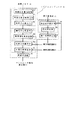
このため本発明のうちの請求項1に記載の発明では、図1に示すように計測対象者に応じて計測誤差を補正する補正係数を算出し、該補正係数を用いて前記計測対象者の視線方向を計測する視線方向計測装置において、前記計測対象者の眼球の位置を検出する眼球位置検出手段Aと、前記眼球の回転角を検出する眼球回転角検出手段Bと、前記補正係数を記憶する補正係数記憶手段Cと、該補正係数記憶手段Cに記憶された補正係数を用い前記眼球位置及び前記眼球回転角に基づいて前記計測対象者の視線方向を算出する視線方向算出手段Dと、
予め設定した注視対象に該当する機器の操作が検出されると操作信号を出力する第1の操作検出部E1と、前記機器の位置を予め記憶する機器位置記憶部E2と、前記第1の操作検出部E1から操作信号が出力された時、前記機器位置記憶部E2に記憶された当該機器の位置を基に算出される機器方向と前記視線方向算出手段Dで算出された視線方向とのずれ量を求め、該ずれ量が予め設定した閾値未満の時には前記補正係数記憶手段Cに記憶された補正係数の更新を行う判定をする補正係数更新判定部E3と、該補正係数更新判定部E3で更新を行う判定がなされると前記ずれ量を補正する新たな補正係数を算出し、前記補正係数記憶手段Cに記憶された補正係数の更新を行う第1の補正係数算出部E4と、を有する補正係数更新手段Eと、を備えて構成されたことを特徴とする。
【0009】
かかる構成によれば、眼球位置検出手段A及び眼球回転角検出手段Bで検出された眼球位置及び眼球回転角に基づいて、視線方向算出手段Dで計測対象者の視線方向が補正係数を考慮して算出されると共に、補正係数更新手段Eにおいて、第1の操作検出部E1から操作信号が出力された時に、補正係数更新判定部E3において視線方向と機器方向とのずれ量が閾値未満と判定された場合、即ち、予め設定した注視対象に該当する機器を計測対象者が注視した時に、第1の補正係数算出部E4で補正係数記憶手段Cに記憶された補正係数の更新が行われるようになる。
【0010】
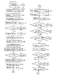
また、請求項2に記載の発明では、図2および図3に示すように計測対象者に応じて計測誤差を補正する補正係数を算出し、該補正係数を用いて前記計測対象者の視線方向を計測する視線方向計測装置において、前記計測対象者の眼球の位置を検出する眼球位置検出手段Aと、前記眼球の回転角を検出する眼球回転角検出手段Bと、前記補正係数を記憶する補正係数記憶手段Cと、該補正係数記憶手段に記憶された補正係数を用い前記眼球位置及び前記眼球回転角に基づいて前記計測対象者の視線方向を算出する視線方向算出手段Dと、予め設定した注視対象の位置を記憶する注視対象位置記憶部E5と、前記注視対象に関連して予め設定した機器の操作が検出されると操作信号を出力する第2の操作検出部E8と、該第2の操作検出部E8からの操作信号に応じて、所定の計測回数間に前記視線方向算出手段Dで算出された複数の視線方向の分布状態及び変化状態に基づいて注視位置を推定する注視位置推定部E6と、該注視位置推定部E6で推定された注視位置と前記注視対象位置記憶部E5に記憶された前記注視対象の位置との差異に応じて新たな補正係数を算出し、前記補正係数記憶手段Cに記憶された補正係数の更新を行う第2の補正係数算出部E7と、を備えて構成されたことを特徴とする。
【0011】
かかる構成によれば、眼球位置検出手段A及び眼球回転角検出手段Bで検出された眼球位置及び眼球回転角に基づいて、視線方向算出手段Dで計測対象者の視線方向が補正係数を考慮して算出されると共に、補正係数更新手段Eにおいて、第2の操作検出部E8からの操作信号に応じ、注視位置推定部E6で複数の視線方向の分布状態及び変化状態に基づいて注視位置が推定され、該注視位置と注視対象位置記憶部E5に記憶された注視対象の位置との差異に応じて第2の補正係数算出部E7で補正係数記憶手段Cに記憶された補正係数の更新が行われるようになる。
【0016】
【発明の効果】
このように、本発明のうちの請求項1に記載の発明は、補正係数を更新する際に、補正係数更新手段において、計測対象者が予め設定した機器を操作した時の視線方向及びその機器方向から、計測対象者が注視対象(機器)を注視したことを計測対象者に意識されることなく自動的に判断することによって、正確に且つ確実に補正係数の更新を行うことができるため、誤差の少ない正確な視線計測が可能となる。また、眼球位置検出手段で眼球位置を計測することによって、計測対象者の眼球位置が移動しても視線方向を一意に決めることができる。
【0017】
また、請求項2に記載の発明は、補正係数を更新する際に、補正係数更新手段において、注視対象に関連する機器の操作情報に応じて注視位置推定部が視線方向算出手段で算出された視線方向の分布状態及び変化状態に基づいて注視位置を推定することによって、正確に且つ確実に補正係数の更新を行うことができるため、眼球位置の移動する計測対象者の視線方向を少ない誤差で正確に計測することができる。
【0019】
【発明の実施の形態】
以下、本発明の実施形態を図面に基づいて説明する。
本発明の第1の実施形態では、車両に視線方向計測装置を搭載し、特定の機器が運転者によって操作されると補正係数を自動的に算出し、その補正係数を用いて計測された運転者の視線方向を基に、例えば、オーディオ、エアコン、ラジオ及びASCDの視線によるオン・オフの切り替えを行う場合について説明する。
【0020】
図4は、第1の実施形態の視線方向計測装置の構成を示す図である。
図4において、本装置は、計測対象者としての運転者の眼球部に光を照射し、該眼球部を撮影した画像を記憶する眼球撮影部10と、後述する特定の機器が操作されると操作信号を出力する第1の操作検出部E1としての操作検出部20と、オーディオ、エアコン、ラジオ及びASCDの動作を制御するコントローラ部30と、オーディオ、エアコン、ラジオ及びASCDの動作状態を表示する表示部40と、眼球撮影部10で得た画像及び操作信号検出部20の出力信号を基に運転者の視線方向を演算してコントローラ部30及び表示部40に制御信号を出力するマイクロコンピュータ50と、マイクロコンピュータ50の演算結果及び前記特定の機器の位置等を記憶するメモリ部70とで構成される。
【0021】
眼球撮影部10は、運転者の面前で眼球部に向けて設けられた2つの発散照明11,12 と、運転者の眼球部を撮影する2つのカメラ13,14 と、カメラ13,14 で撮影された画像を A/D変換する A/D変換器15と、A/D 変換器15で変換された画像を記憶する画像メモリ16と、発散照明11,12 及び A/D変換器15を制御する照明発光制御部17とで構成される。発散照明11,12 は、例えば、人間には不可視の赤外光を発光し、運転席付近のレイアウトの一例を示す図5の(a)に示すように、相対的に異なる所定の位置、例えばステアリングホイールの両側方等にそれぞれ設置され、照明発光制御部17に接続される。カメラ13,14 は、例えば、撮像素子にCCDを備え、図5の(a)に示すように、カメラ13と発散照明11とが共軸系に配置され、同様にカメラ14と発散照明12とが共軸系に配置される。照明発光制御部17は、発散照明11,12 を交互に点灯させる制御信号を発散照明11,12 に出力すると共に、発散照明11が点灯したときにカメラ13から画像を取り込み、発散照明12が点灯したときにカメラ14から画像を取り込むように A/D変換器15を制御する信号を出力する。画像メモリ16は、 A/D変換器15で A/D変換されたカメラ13,14 からの各画像を記憶する。
【0022】
操作検出部20は、乗員によって機器操作が行われるとキャリブレーション動作を開始する特定の機器として、例えば、右サイドミラー、左サイドミラー及びナビゲーション装置を設定した場合において、右サイドミラー操作検出部21と、左サイドミラー操作検出部22と、ナビゲーション装置操作検出部23とで構成される。これらの機器に設定する理由は、左右サイドミラーでは、運転者が交代した場合に殆どの運転者が位置確認を行うので、この機会を捉えキャリブレーション動作を行えば走行開始前には正確な補正係数が算出できるためである。また、ナビゲーション装置では、走行開始後であっても操作が行われることがあり、この機会を捉えて補正係数を算出し更新を行えるようにするためである。右サイドミラー操作検出部21及び左サイドミラー操作検出部22は、各々のサイドミラーの角度を調節するスイッチが操作された時に操作信号をマイクロコンピュータ50に出力する。ナビゲーション装置操作検出部23は、ナビゲーション装置が操作された時に操作信号をマイクロコンピュータ50に出力する。
【0023】
コントローラ部30は、オーディオコントローラ31と、エアコンコントローラ32と、ラジオコントローラ33と、ASCDコントローラ34と、各コントローラ31〜34のオン・オフを切り替えるコントローラ切り替え部35とで構成される。コントローラ切り替え部35は、後述するように運転者の視線に応じてマイクロコンピュータ50から出力される制御信号を入力し、入力した制御信号に対応するコントローラのオン・オフを切り替える信号を出力する。
【0024】
表示部40は、ヘッドアップディスプレイ(以下、HUDとする)41と、HUD41の表示を制御する表示制御部42とで構成される。HUD41は、上記図5の(a)に示すように運転席付近に設けられ、図5の(b)に示すように、オーディオ、エアコン、ラジオ及びASCDそれぞれのオン・オフを視線によってスイッチするための視線スイッチエリアAsを表示し、各々の機器がスイッチされると表示が短時間反転される。表示制御部42は、マイクロコンピュータ50より出力される制御信号を入力し、入力した信号に対応するHUD41の表示を切り替える信号を出力する。
【0025】
マイクロコンピュータ50は、眼球撮影部10で撮影し記憶した画像に基づいて運転者の眼球位置を演算する機能と、運転者の眼球回転角を演算する機能と、操作検出部20の出力に応じて後述する補正係数の更新を行うか否を判定する機能と、補正係数を算出する機能と、眼球位置及び眼球回転角を用い補正係数を考慮して運転者の視線方向を算出し注視対象を判定する機能と、運転者の視線の停留時間を判断しコントローラ部30及び表示部40を制御する信号を生成する機能とを有する。
【0026】
ここで、マイクロコンピュータ50の各機能について図6に示す機能ブロック図を参照しながら詳細に説明する。
図6において、角膜反射像抽出部51は、眼球撮影部10の画像メモリ16に接続され、カメラ13で撮影し画像メモリ16に記憶された画像G1及びカメラ14で撮影し画像メモリ16に記憶された画像G2をそれぞれ読み込み、画像処理して各画像中の角膜反射像を抽出する。角膜反射像とは、眼球への照射光が眼球を構成する角膜等の光学系の各面で反射、屈折することによって生じる像であり、プルキンエ像とも呼ばれるものである。ここでは、画像G1より抽出された発散照明11の角膜反射像の画像中の座標P1を(P1x, P1y)とし、また、画像G2より抽出された発散照明12の角膜反射像の画像中の座標P2を(P2x,P2y)とする。
【0027】
角膜反射直線算出部52は、角膜反射像抽出部51により抽出された角膜反射像の各座標P1, P2を用いて、角膜反射像とその角膜反射像に対応するカメラ焦点とを結ぶ直線をそれぞれ求める。この直線は、角膜反射像の画像中の座標P1, P2が算出されるとその角膜反射像を撮影したカメラのCCD及びカメラレンズ焦点の位置関係から一意に算出できる。角膜反射像の座標P1とカメラ13の焦点とを結ぶ直線をL1とし、また、角膜反射像の座標P2とカメラ14の焦点とを結ぶ直線をL2とする。
【0028】
眼球中心算出部53は、角膜反射直線算出部52で求められた直線L1,L2の交点を算出することにより、眼球中心(正確には角膜球中心)Oの位置を算出する。ここでは、発散照明11とカメラ13とが共軸系に配置されているため直線L1は必ず眼球中心Oを通過し、また、発散照明12とカメラ14とが共軸系に配置されているため直線L2も必ず眼球中心Oを通過するので、直線L1,L2の交点が眼球中心Oとなる。算出した眼球中心Oの3次元空間における座標を(Ox,Oy,Oz)とする。
【0029】
このようにして、角膜反射像抽出部51、角膜反射直線算出部52及び眼球中心算出部53が眼球位置演算手段Aとして機能する。
瞳孔中心算出部54は、画像メモリ16に記憶された画像G1を画像処理して瞳孔部分を抽出し、瞳孔部分の中心(重心)の画像中の座標を求める。画像G1から求めた画像中の瞳孔中心座標をQ1(Qx,Qy)とする。
【0030】
眼球回転角算出部55は、角膜反射像抽出部51で求めた角膜反射像の座標P1(P1x,P1y)と瞳孔中心算出部54で求めた瞳孔中心座標Q1(Qx,Qy)とから、カメラ13の撮影方向(発散照明11とカメラ13との共軸方向)に対する眼球の回転角θ’を算出する。この眼球回転角の算出方法の詳細は、例えば、上述の特開平7-151958号公報等で公知であり、ここではその概略のみを説明する。
【0031】
一般に眼球の回転角θ’は、角膜球中心から瞳孔中心までの標準的な距離をLocとし、距離Locに対する個人差を考慮する補正係数をA1とし、カメラのレンズ系に対する角膜球中心の位置関係により決まる補正係数(倍率)をβとすると、次の(1)式の関係を満たす。
β×A1×Loc× sinθ' =Q1−P1 (1)
従って、眼球の回転角θ’は、次の(2)式により求められる。
【0032】
θ’=ARCSIN{(Q1−P1)/(β×A1×Loc)} (2)
本実施形態の眼球回転角算出部55では、画像G1内の水平方向(x軸方向)に対する回転角θx’及び垂直方向(y軸方向)に対する回転角θy’が算出される。尚、補正係数A1は、後述するようにメモリ部70の補正係数記憶部72に記憶された値が用いられる。
【0033】
このようにして、瞳孔中心算出部54及び眼球回転角算出部55が眼球回転角検出手段Bとして機能する。尚、ここでは画像G1から瞳孔中心を求め眼球回転角を算出する構成としたが、勿論、画像G2から眼球回転角を算出しても良く、あるいは、画像G1,G2よりそれぞれ瞳孔中心、眼球回転角を求め平均化しても良い。
【0034】
視線方向算出部56は、眼球回転角算出部55で求めた眼球回転角θ’と眼球中心算出部53で求めた眼球中心Oとから視線方向eを算出する。ここでは、視線方向eを直線の方程式として表すものとする。
ただし、前述の特開平7-151958号公報等にも記載されているように、多くの場合、眼球の視軸(視線方向e)と光軸(眼球の回転角θ’方向)は一致しないため、光軸が算出されると光軸と視軸との角度補正をすることにより視軸が求められる。ここでは、光軸の角度補正係数をδとし、角度補正係数δに対する個人差を考慮する補正係数をB1とすると、視軸の回転角θは次の(3)式となる。
【0035】
θ=θ’±(B1×δ) (3)
ここで符号±は、運転者に関して右への回転角を正とすると、カメラ13の撮影する運転者の目が左目の場合は+、右目の場合は−の符号が選択される。実際に視線方向算出部56では、水平方向の補正係数をB1x、垂直方向の補正係数をB1yとして、画像G1内の水平方向(x軸方向)に対する視軸の回転角θx、及び垂直方向(y軸方向)に対する視軸の回転角θyが算出される。尚、補正係数B1x,B1yはメモリ部70の補正係数記憶部72に記憶された値が用いられる。
【0036】
そして、算出された視軸の回転角θx,θyを用いて極座標系で表される視線方向eを直交座標系に変換することにより、視線方向eの方向ベクトル(Ex,Ey,Ez)を算出すると、視線方向eは、眼球中心Oを始点とし方向ベクトル(Ex,Ey,Ez)を用いて次の(4)式で表される直線L3となる。
(X−Ox)/Ex=(Y−Oy)/Ey=(Z−Oz)/Ez (4)
注視対象判定部57は、後述するメモリ部70の機器位置記憶部71に予め記憶された車両内の特徴的な箇所の座標、具体的には、HUD41の各視線スイッチエリアAsの中心位置の座標を基に、視線方向算出部56で求めた視線方向eを用いて運転者の注視対象を判定する。この注視対象の判定は、視線方向eに最も近い視線スイッチエリアAsの中心位置方向について、機器位置記憶部71に記憶された前記視線スイッチエリアAsの中心位置の座標と眼球中心Oとを通る直線L4の方程式を求め、この直線L4と視線方向算出部56で求めた直線L3との交差角φ1を求める。そして、交差角φ1が予め設定した閾値Th1未満の時には、運転者が前記視線スイッチエリアAsを見ていると判定し、交差角φ1が閾値Th1以上の時には、運転者が他の箇所を見ていると判断する。直線L3と直線L4との交差角φ1の算出は、例えば、直線L3の方向ベクトルと直線L4の方向ベクトルとの内積をとるこによって求められる。
【0037】
このように、視線方向算出部56及び注視対象判定部57が視線方向算出手段Dとして機能する。
検出誤差算出部58は、操作検出部20から操作信号が送出された場合に、その操作信号に対応する機器についてメモリ部70の機器位置記憶部71に予め記憶させた位置情報を読み込み、操作信号が送出された時点での眼球中心Oと操作信号に対応する機器とを通る直線L5の方程式を算出する。例えば、右サイドミラーの調整操作が行われ右サイドミラー操作検出部21よりマイクロコンピュータ50に操作信号が送出されると、機器位置記憶部71に記憶された右サイドミラーの中心位置を読み込んで、眼球中心Oと右サイドミラーの中心位置とを通る直線L5の方程式を求める。そして、その操作信号が送出された時に視線方向算出部56で求められた視線方向eを表す直線L3と直線L5との交差角φ2を算出する。尚、左サイドミラー操作検出部22あるいはナビゲーション装置操作検出部23から操作信号が送出される場合も、右サイドミラー操作検出部22から操作信号が送出される場合と同様の演算処理が行われる。ただし、ナビゲーション装置の場合、操作スイッチの中心位置が機器位置記憶部71より読み込まれる。
【0038】
更新判定部59は、検出誤差算出部58で求めた交差角φ2と予め設定した閾値Th2とを比較する。交差角φ2が閾値Th2未満の場合には、後述する新たな補正係数を算出し補正係数の更新を行う判定をし、交差角φ2が閾値Th2以上の場合には、補正係数の更新を行わない判定をする。
ここで、閾値Th2の設定について説明する。
【0039】
補正係数の更新を判定する際、操作検出部20から出力された操作信号だけではその操作が運転者によるものか、あるいはその他の乗員によるものかの区別がつかない。運転者に応じた補正係数を求めるためには、運転者による操作のみに限定する必要がある。運転者によって操作が行われる時、運転者の視線は操作する機器の方向を向き、他の乗員によって操作が行われる時、運転者の視線は該当する機器の方向とは異なる方向を向くものと考えられる。そこで、操作信号の出力された時点での視線方向算出部56で算出された運転者の視線方向eが操作された機器の方向に略一致する、即ち、交差角φ2が十分に小さい時に、運転者によって操作が行われたものと判断する。
【0040】
ただし、視線方向算出部56で求められた視線方向eは、操作検出部20から操作信号が出力される以前の補正係数(装置始動時には補正係数の初期設定値)を考慮して算出したものであるため誤差を含む可能性がある。一般に、補正係数が正確でない場合の視線方向eの計測誤差は数度程度と考えられる。そこで、例えば、補正係数の初期設定値には大多数の乗員から求めた補正係数の平均値を使用する等して、運転者の視線方向eを求めれば、その視線方向eは数度程度の誤差精度で算出されることになる。従って、例えば、閾値Th2を10°程度に設定し、交差角φ2と閾値Th2とを比較することによって、運転者が機器操作を行ったか否かを十分に判定することが可能となる。
【0041】
このようにして、検出誤差算出部58及び更新判定部59が補正係数更新判定部E3として機能する。
第1の補正係数算出部E4としての補正係数算出部60は、更新判定部59で補正係数の更新が判定された場合に新たな補正係数を算出する。この補正係数は、例えば、右サイドミラー操作検出部21より操作信号が送出され、検出誤差算出部58で求めた交差角φ2が更新判定部59で閾値Th2未満と判定された時には、運転者は右サイドミラーの中心を見ているものとして、運転者の視線方向e(直線L3)を直線L5に一致させる新たな補正係数A1,B1x,B1yを算出する。尚、左サイドミラーあるいはナビゲーション装置についても右サイドミラーと同様にして補正係数を算出する。
【0042】
停留判断部61は、運転者の視線が1つの視線スイッチエリアAsに停留している時間を計測し、計測した停留時間が所定の時間Th3を越えるとコントローラ部30及び表示部40を制御する信号を生成する。
前述のメモリ部70は、機器位置記憶部E2としての機器位置記憶部71に、右サイドミラー及び左サイドミラーの中心位置、ナビゲーション装置のスイッチ位置、HUD41の各視線スイッチエリアAsの中心位置等が予め記憶されると共に、補正係数記憶手段Cとしての補正係数記憶部72にマイクロコンピュータ50で算出された補正係数A1,B1x,B1yが記憶される。
【0043】
次に、第1の実施形態の動作について、例えば、運転者が視線スイッチエリアAsのエアコンに対応する部分を注視してエアコンのオン・オフを切り替える場合の視線スイッチ動作及び補正係数の更新動作を図7及び図8に示すフローチャートに基づいて説明する。
まず、視線スイッチ動作について説明する。
【0044】
図7において、運転者がエアコンの操作をしたいと考え、HUD41の各視線スイッチエリアAsのうちのエアコン領域(図5の(b)中のA/C領域)を注視した状態で、視線方向の計測が開始されると、
ステップ101 (図中、S101 で示し、以下同様とする)では、マイクロコンピュータ50の停留判断部61で計測されるタイムカウンタtの値が初期化される。タイムカウンタtは運転者の視線が注視対象に停留している時間を計測するカウンタである。
【0045】
ステップ102 では、照明発光制御部17からの信号により発散照明11が点灯される。
ステップ103 では、カメラ13で撮影された運転者の眼球の画像G1が、 A/D変換器15を介して画像メモリ16に記憶される。
ステップ104 では、照明発光制御部17からの信号により発散照明11が消灯される。
【0046】
ステップ105 では、マイクロコンピュータ50の角膜反射像抽出部51において、画像メモリ16に記憶された画像G1が読み込まれ角膜反射像の座標P1が抽出される。この座標P1は画像上の2次元の座標である。
ステップ106 では、ステップ105 で角膜反射像の座標P1が抽出されたか否かが判別される。座標P1が抽出されない場合には、ステップ101 に戻り、座標P1が抽出された場合には、ステップ107 に進む。
【0047】
ステップ107 では、角膜反射直線算出部52において、直線L1が算出される。
ステップ108 では、照明発光制御部17からの信号により発散照明12が点灯される。
ステップ109 では、カメラ14で撮影された運転者の眼球の画像G2が、 A/D変換器15を介して画像メモリ16に記憶される。
【0048】
ステップ110 では、照明発光制御部17からの信号により発散照明12が消灯される。
ステップ111 では、角膜反射像抽出部51において、画像メモリ16に記憶された画像G2が読み込まれ角膜反射像の座標P2が抽出される。この座標P2は画像上の2次元の座標である。
【0049】
ステップ112 では、ステップ111 で角膜反射像の座標P2が抽出されたか否かが判別される。座標P2が抽出されない場合には、ステップ101 に戻り、座標P2が抽出された場合には、ステップ113 に進む。
ステップ113 では、角膜反射直線算出部52において、直線L2が算出される。
ステップ114 では、眼球中心算出部53において、直線L1,L2の交点、即ち、眼球中心Oの座標が算出される。眼球中心Oは、3次元空間中の座標である。
【0050】
ステップ115 では、瞳孔中心算出部54において、画像G1より瞳孔中心の座標Q1が算出される。この座標Q1は画像上の2次元の座標である。
ステップ116 では、眼球回転角算出部55において、ステップ105 で求めた角膜反射像の座標P1とステップ115 で求めた瞳孔中心の座標Q1とから、メモリ部70の補正係数記憶部72に記憶された補正係数A1を考慮して眼球回転角θx’,θy’が算出される。
【0051】
ステップ117 では、視線方向算出部56において、ステップ116 で求めた眼球回転角θx’,θy’とステップ114 で求めた眼球中心Oとから、補正係数記憶部72に記憶された補正係数B1x,B1yを考慮して視軸の回転角θx、θyが算出される。
ステップ118 では、ステップ117 で求めた視軸の回転角θx、θyより視線方向eを表す直線L3の方程式が算出される。
【0052】
ステップ119 では、マイクロコンピュータ50において右サイドミラー操作検出部21からの操作信号の有無が調べられる。操作信号がマイクロコンピュータ50に送信されている場合には、図8に示すステップ128 に進み、後述する補正係数の更新判断処理が行われる。操作信号が送信されていない場合には、ステップ120 に進む。
【0053】
ステップ120 では、左サイドミラー操作検出部22からの操作信号の有無が調べられる。操作信号がマイクロコンピュータ50に送信されている場合には、図8に示すステップ129 に進み、補正係数の更新判断処理が行われる。操作信号が送信されていない場合には、ステップ121 に進む。
ステップ121 では、ナビゲーション装置操作検出部23からの操作信号の有無が調べられる。操作信号がマイクロコンピュータ50に送信されている場合には、図8に示すステップ130 に進み、補正係数の更新判断処理が行われる。操作信号が送信されていない場合には、ステップ122 に進む。
【0054】
ステップ122 では、注視対象判定部57において、視線方向eに最も近い視線スイッチエリアAs(ここではエアコン領域)の中心位置と眼球中心Oとを通る直線L4の方程式が算出される。
ステップ123 では、ステップ118 で求めた直線L3とステップ122 で求めた直線L4との交差角φ1が算出される。
【0055】
ステップ124 では、ステップ123 で求めた交差角φ1と閾値Th1との比較が行われる。交差角φ1が閾値Th1未満の時は、ステップ125 へ進み、交差角φ1が閾値Th1以上の時は、ステップ101 に戻り新規に処理を開始する。
ステップ125 では、ステップ124 で運転者の注視状態、ここでは運転者が視線スイッチエリアAsのエアコン領域を注視している状態が判断されると、停留判断部61でタイムカウンタtの値がインクリメントされる。
【0056】
ステップ126 では、タイムカウンタtの値と所定の時間Th3との比較が行われる。タイムカウンタtの値が時間Th3未満の時は、ステップ102 に戻り停留時間の計測を継続する。タイムカウンタtの値が時間Th3以上の時は、ステップ127 に進む。
ステップ127 では、ステップ126 で運転者の視線が視線スイッチエリアAsのエアコン領域に所定の時間Th3以上停留していることが判断されると、マイクロコンピュータ50より、エアコンコントローラ32を選択しエアコンスイッチのオン・オフを切り替える制御信号がコントローラ切り替え部35に出力されると共に、HUD41のエアコン領域の表示を短時間反転させる制御信号が表示制御部42に出力される。
【0057】
このようにして視線によるエアコンのスイッチの切り替えが行われ、上述の動作を繰り返すことによって、それぞれの装置の視線によるスイッチの切り替え操作が行われる。
次に、補正係数の更新動作について説明する。
図8において、ステップ128 では、ステップ119 で右サイドミラー操作検出部21からの操作信号の出力が確認されると、マイクロコンピュータ50は、メモリ部70の機器位置記憶部71に記憶された右サイドミラーの中心位置の座標を読み込み、ステップ131 に進む。
【0058】
ステップ129 では、ステップ120 で左サイドミラー操作検出部22からの操作信号の出力が確認されると、マイクロコンピュータ50は、機器位置記憶部71に記憶された左サイドミラーの中心位置の座標を読み込み、ステップ131 に進む。
ステップ130 では、ステップ121 でナビゲーション装置操作検出部23からの操作信号の出力が確認されると、マイクロコンピュータ50は、機器位置記憶部71に記憶されたナビゲーション装置のスイッチの中心位置の座標を読み込み、ステップ131 に進む。
【0059】
ステップ131 では、検出誤差算出部58において、ステップ128 〜ステップ130 のいずれか1つのステップで読み込んだ座標とステップ114 で算出した眼球中心Oとを通る直線L5が算出される。
ステップ132 では、ステップ118 で求めた直線L3とステップ131 で求めた直線L5との交差角φ2が算出される。
【0060】
ステップ133 では、更新判定部59において、ステップ132 で求めた交差角φ2と閾値Th2との比較が行われる。交差角φ2が閾値Th2未満の時は、ステップ134 に進み補正係数の更新処理が行われ、交差角φ2が閾値Th2以上の時は、ステップ101 に戻り新規に処理が開始される。
ステップ134 では、補正係数算出部60において、新たな補正係数A1,B1x,B1yが算出される。
【0061】
ステップ135 では、補正係数記憶部72に記憶された補正係数がステップ134 で算出した新たな補正係数に更新され、ステップ101 に戻る。
このように、ステップ119 〜ステップ121 で操作信号が確認されると、ステップ128 〜ステップ135 によって補正係数の更新動作が行われる。
上述のように、第1の実施形態によれば、キャリブレーション動作を行い補正係数を更新する際に、それぞれの機器の操作信号と、操作された機器の位置に関する情報と、計測された運転者の視線情報とから補正係数の更新を行うか否かを判定し、運転者の視線方向eが操作された機器の方向と略一致する時のみ補正係数を更新することによって、正確に且つ確実に補正係数の更新を行うことが可能となる。また、一連のキャリブレーション動作は、運転者が意識しなくても自動的に行われるため、誤差の少ない正確な視線計測が可能となる。更に、眼球位置を計測することによって、運転者の眼球位置が移動しても視線方向を一意に決めることができる。
【0062】
尚、第1の実施形態では、機器操作が行われるとキャリブレーション動作を開始する機器を、右サイドミラー、左サイドミラー及びナビゲーション装置に設定したが、本発明はこれに限らず種々の機器に設定することができ、各機器の操作を行っている時の視線と操作する位置とを対応させることで第1の実施形態と同様の処理を行うことができる。例えば、ルームミラー、カーステレオ、ラジオ、エアコンやグローブボックス等に設定することができる。また、例えば、シフトレバー、ライト、ワイパースイッチ、ウインカスイッチ等に設定した場合には、それぞれの操作を運転者がレバーやスイッチを見ながら行なった時に補正係数の更新を行うようにすれば良い。更に、例えば、予めアイコンを表示し運転者にタッチさせるタッチパネル式の表示装置や、CRT上にカーソルを表示して運転者にカーソルの移動等を行わせる表示装置に設定して、運転者が操作時にアイコンやカーソルの位置を注視している機会を捉えて補正係数を算出することも可能である。加えて、乗車時には運転者はマスターキーを車両に挿入するが、この動作は鍵穴を見ながら行われることが多く、この機会を捉えて補正係数を算出することもできる。この場合には、例えば、車両に運転者が乗り込んだ時点、あるいは運転席ドアを開閉した後の一定時間、視線方向計測装置の動作させれば走行開始前には補正係数が算出されていることになる。
【0063】
次に、本発明の第2の実施形態について説明する。
第2の実施形態では、補正係数の更新動作を運転者の視線方向の分布状態に基づいて行う場合について説明する。
図9は、第2の実施形態の視線方向計測装置の構成を示す図である。ただし、第1の実施形態の構成と同一の部分には同一符号を付して説明を省略する。
【0064】
図9において、第2の実施形態の構成が第1の実施形態の構成と異なる部分は、第1の実施形態におけるマイクロコンピュータ50への操作検出部20からの入力がなくなり、マイクロコンピュータ50及びメモリ部70に代えてマイクロコンピュータ50’及びメモリ部70’を用いた点である。その他の構成は第1の実施形態の構成と同一である。
【0065】
まず、マイクロコンピュータ50’の機能を、図10に示す機能ブロック図に基づいて説明する。ただし、第1の実施形態のマイクロコンピュータ50の機能と同一の機能ブロックには同一符号を付して説明を省略する。図10において、マイクロコンピュータ50と異なる機能ブロックは、注視位置推定部E6としての注視位置推定部57’及び第2の補正係数算出部E7としての補正係数算出部60’である。
【0066】
注視位置推定部57’は、第1の実施形態と同様の視線方向算出部56で複数の計測周期に渡って算出された運転者の視線方向eを表す複数の直線L3(それぞれの直線をL31,L32,...,L3nとする)を基に、運転者の視線方向eの分布を求め、その分布状態を考慮して運転者が注視している後述する特徴点位置の推定を行うと共に、前記分布の中心を求める。
【0067】
ここで、視線方向の分布の求め方の一例を図11を用いて説明する。
図11において、視線方向の分布を求めるにあたり、運転者より1m程度前方の位置に仮想面Vを設ける。そして、必ずしも仮想面V上にはない注視点80を眼球位置が移動する運転者が注視する場合(図11では、少しづづ位置の異なる運転者の眼球81,82,83が示してある) を考えると、運転者の視線方向eを表す直線は、眼球81について直線L31、眼球82について直線L32、眼球83について直線L33というように眼球の位置に応じて無数に存在する。従って、これら直線L31,L32,L33と仮想面Vとの交点を求め、その交点の分布範囲を注視点80を注視する時の視線分布領域Sとする。
【0068】
図12は、図11の視線分布領域Sを車両内で考えた場合を示す。運転者の視線方向eが正確に検出されていれば、車両走行中の視線分布領域は、例えば、前方注視分布91、左サイドミラー注視分布92、右サイドミラー注視分布93、ルームミラー注視分布94を始め、図示されていないがオーディオ機器やメータパネル等となり、運転中に情報を取得するための幾つかの特徴的な注視対象(特徴点)を見るため、視線にも特徴的な分布が発生する。またこの時、例えば、自動車技術,Vol.39,No.5,1985,PP.503等に記載されている様に、運転者は運転中の多くで前方を注視しており、計器類に視線を向ける場合でも、前方から計器類に視線をやり視認が完了するとまた視線が前方に戻ることが多い。これは視線の移動、即ち視線のリンク分析を行うと、前方注視分布91と左サイドミラー注視分布92との移動、前方注視分布91と右サイドミラー注視分布93との移動及び前方注視分布91とルームミラー注視分布94との移動が比較的多く発生することを意味する。即ち、仮想面V上の視線方向の分布と変化を分析すれば、左サイドミラー注視分布92は左サイドミラーを注視した場合の分布であり、右サイドミラー注視分布93は右サイドミラーを注視した場合の分布であり、ルームミラー注視分布94はルームミラーを注視した場合の分布であことが推定できる。また、統計的にそれぞれの特徴点は視線分布領域の中心に存在すると推定できる。
【0069】
実際に注視位置推定部57’で上記の処理を行う場合には、視線分布領域Sを構成する点、即ち、直線L31と仮想面Vとの交点と、その時の眼球81の位置や、直線L32と仮想面Vとの交点と、その時の眼球82の位置を記憶しておけば視線方向分布とリンクを分析することが可能となる。このようにして注視位置推定部57’では、注視点位置が推定され、後述するメモリ部70’の注視対象位置記憶部71’に記憶された特徴点の位置情報から、眼球中心算出部53で求められた眼球中心Oとその特徴点を通る直線L5を表す方程式が算出され、視線方向算出部56で求めた直線L3と直線L5との交差角φ2が算出される。
【0070】
補正係数算出部60’は、注視位置推定部57’で推定した注視対象位置(視線分布領域の中心)と注視対象位置記憶部71’に記憶された特徴点の位置情報を用いて補正係数を算出する。補正係数が正確でない場合、視線の分布は例えば図13のようになる。しかし、前述のように注視位置推定部57’で視線方向分布とリンクを分析すれば、図13の、例えば左サイドミラー注視分布92' の位置は、本来図12の左サイドミラー注視分布92の位置に存在することが推測できる。従って、補正係数算出部60’では、左サイドミラー注視分布92' の位置を左サイドミラー注視分布92の位置に合わせるように補正係数が算出される。
【0071】
また、前述のメモリ部70’は、注視対象位置記憶部E5としての注視対象位置記憶部71’に左右サイドミラーやルームミラーの中心位置等、特徴点の位置が予め記憶されると共に、補正係数記憶手段Cとしての補正係数記憶部72’にマイクロコンピュータ50で算出された補正係数A1,B1x,B1y等の演算結果が記憶される。
【0072】
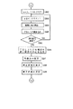
次に、第2の実施形態の動作を図14に示すフローチャートに基づいて説明する。ただし、第1の実施形態の動作を示すフローチャートと同じ部分には同一符号を付して説明を省略する。
図14において、視線方向の計測が開始されると、ステップ201 で計測回数nが初期化される。計測回数nは補正係数の算出を行うか否かを判定するためのデータ数をカウントするパラメータである。また、視線方向の分布状態に関する情報を記録するメモリ部70' に設定されたテーブル(TBL)がクリアされる。
【0073】
ステップ202 では、計測回数nがインクリメントされる。
そして、第1の実施形態と同様のステップ101 〜ステップ117 までの動作が行われ、眼球中心O、視軸回転角θx,θy等が算出される。
ステップ203 では、n回目の計測回数のときの運転者の視線方向eを表す直線L3nが算出される。
【0074】
ステップ204 では、ステップ203 で求めた直線L3nと仮想面Vとの交点を算出し、算出した交点の位置と共にその時の眼球中心Oの位置がメモリ部70' のテーブルに記憶される。
ステップ205 では、計測回数nが、予め設定した計測回数、ここでは例えば 2万回を越えたか否かが判別される。計測回数nが2万回を越えると、補正係数を求める処理を行うため、図15のフローチャートに示すステップ206 に進む。計測回数nが2万回以下の時にはステップ122 に進む。
【0075】
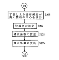
ステップ122 〜ステップ127 は、第1の実施形態と同様の視線スイッチ動作が行われる。図15に示すステップ206 では、注視位置推定部57’において、テーブルに記憶された直線L31〜L3nに関する複数のデータが読み込まれ、これら複数のデータに基づいて視線方向の分布状態が求められる。そして分布頻度が高い箇所及びリンク分析の結果より、各視線分布領域が推定され、それぞれの視線分布領域の中心が算出される。
【0076】
ステップ207 では、ステップ206 で求められた各視線分布領域の中心がどの特徴点、例えば、右サイドミラーの位置等に対応するかが推定される。
ステップ208 では、ステップ207 で対応付けられたそれぞれの特徴点の位置について、メモリ部70' の注視対象位置記憶部71’に記憶された正確な位置情報が読み込まれ、その読み込まれた位置と視線分布領域の中心位置が一致するものとして新たな補正係数A1,B1x,B1yが算出される。
【0077】
そして、第1の実施形態と同様のステップ135 で、メモリ部70' の補正係数記憶部72’に記憶された補正係数がステップ208 で求めた新たな補正係数に更新され、ステップ201 に戻る。
このように、第2の実施形態によれば、運転者の視線方向の分布状態に基づいて注視対象を推定し、その注視対象の位置情報を用いて補正係数を算出、更新することによって、従来の装置あるいは第1の実施形態の装置とは異なり、特定の機器が操作されなくても補正係数の更新が可能となる。また、この場合でも一連の動作は運転者に意識させずに自動的に行われるため、誤差の少ない正確な視線計測が可能となる。
【0078】
尚、第2の実施形態では、走行中に左右サイドミラーやルームミラーの注視位置を推定する構成としたが、本発明はこれに限られるものではない。例えば、ナビゲーション装置で音声案内等の機能を有する装置では、注意を喚起する目的でブザー音等を発生し、これに続けて進行方向の案内を音声情報で呈示する手法がしばしば行われる。この場合、運転者は音声案内の後に表示画面を確認する場合が多い。従って、音声案内発生後の一定時間はナビゲーション装置の表示画面を見る確率が高くなることを考慮して注視対象を推定しても良い。
【0079】
次に、本発明の第3の実施形態について説明する。
第3の実施形態では、第2の実施形態における注視対象の推定動作が機器の操作を考慮して行われる場合について説明する。
図16は、第3の実施形態の視線方向計測装置の構成を示す図である。ただし、第2の実施形態の構成と同一の部分には同一符号を付して説明を省略する。
【0080】
図16において、第3の実施形態の構成が第2の実施形態の構成と異なる部分は、第2の操作検出部E8としての操作検出部20' の出力がマイクロコンピュータ50''に入力される点である。その他の構成は第2の実施形態の構成と同一である。
操作検出部20' は、運転者による操作を検出する特定の機器として、例えば、ウインカレバー及びシフトレバーに設定した場合において、右ウインカ操作検出部24と、左ウインカ操作検出部25と、バックギア操作検出部26とで構成される。ウインカレバー及びシフトレバーを設定した理由は、ウインカレバーが操作される前後には、車両の向かう方向やその方向のサイドミラーへの運転者の注視が増えること、また、シフトレバーで後退が選択されるとその前後でルームミラーへの運転者の注視が増えることを利用して注視対象の推定を行うためである。右ウインカ操作検出部24は、ウインカレバーが右方向に操作されたことを検出してマイクロコンピュータ50''に操作信号を送出する。左ウインカ操作検出部25は、ウインカレバーが左方向に操作されたことを検出してマイクロコンピュータ50''に操作信号を送出する。バックギア操作検出部26は、シフトレバーで後退が選択されたことを検出してマイクロコンピュータ50''に操作信号を送出する。
【0081】
マイクロコンピュータ50''は、図17の機能ブロック図に示すように、操作検出部20' から出力される操作信号が注視位置推定部57''に入力される構成で、その他の部分は第2の実施形態のマイクロコンピュータ50’と同一である。次に、第3の実施形態の動作を図18に示すフローチャートに基づいて説明する。ただし、第1、2の実施形態の動作を示すフローチャートと同じ部分には同一符号を付して説明を省略する。
【0082】
図18において、視線方向の計測が開始されると、第1の実施形態の動作と同様に、ステップ101 〜ステップ117 の動作によって眼球中心O、視軸回転角θx,θy等が算出され、第2の実施形態の同様のステップ203 の動作によって運転者の視線方向eを表す直線L3nが算出される。
ステップ301 では、マイクロコンピュータ50''において、操作検出部20' からの操作信号の有無が判別される。操作信号が発生している時は図19のステップ302 に進む。操作信号が発生していない時はステップ122 に進み、第1の実施形態と同様のステップ122 〜ステップ127 で視線スイッチ動作が行われる。
【0083】
図19のフローチャートに示すステップ302 では、第2の実施形態のステップ201 の動作と同様に、計測回数nが初期化されると共にテーブルがクリアされる。
ステップ303 では、第2の実施形態のステップ202 の動作と同様に、計測回数nがインクリメントされる。
ステップ304 では、第2の実施形態のステップ101 〜ステップ203 と同様の一連の動作が行われ直線L3nが算出される。
【0084】
ステップ305 では、第2の実施形態のステップ204 の動作と同様に、直線L3nと仮想面Vとの交点を算出し、算出した交点の位置と共にその時の眼球中心Oの位置がテーブルに記憶される。
ステップ306 では、操作検出部20' からの操作信号が継続して送出されているか否かが判別される。操作信号が継続している場合には、ステップ303 に戻り注視対象の推定を行うためのデータを蓄積していく。操作信号が継続していない場合には、ステップ206 に進み補正係数が算出される。
【0085】
ステップ206 〜ステップ135 では、第2の実施形態の動作と同様に、テーブルに記憶されたデータに基づいて注視対象及び特徴点が推定され、補正係数の算出、更新が行われる。補正係数の更新後はステップ101 に戻る。
このように、第3の実施形態によれば、第2の実施形態の効果に加えて、運転者の注視対象を推定する際、特定の機器の操作を考慮して行うことによって、注視対象の推定がより確実になるため、一層正確且つ確実に補正係数の更新を行うことが可能となる。
【0086】
尚、第3の実施形態では、ウインカレバー及びシフトレバーの操作が行われるとサイドミラー及びルームミラーの注視が増えることを利用する構成としたが、本発明はこれに限られるものではない。例えば、ブレーキを踏む前後にはルームミラーへの注視が増えること、シフトチェンジ時にはシフトレバーへの注視が増えること、停止時には信号への注視が増えること、前方車両に追従して停止する時には前方車両の運転者付近への注視が増えること、ナビゲーション装置装着車では停止時にナビゲーション装置への注視が増えること等を利用することも応用可能である。
【0087】
また、警告灯が点灯した場合、これを見て運転者が動作を開始することがある。例えば、シートベルト未装着の場合に点灯する警告灯が点灯した時、運転者はその表示を見た後にシートベルトを装着するような場合がある。この場合、シートベルトを装着する動作が行われる前には、該当する警告表示灯を見た確率が高いため、この機会を捉えて補正係数を算出することもできる。同様に、例えばサイドブレーキ等の操作が行われた場合でも、その動作が行われる前には該当する警告表示灯を見た確率が高く、この機会を利用しても良い。
【0088】
更に、前記シートベルトの警告表示灯を見た時に補正係数を算出するのに加え、シートベルト装着時にはシートベルト金具を見ながら操作することを考慮して補正係数を算出すれは、略同時に2つの異なった注視位置で補正係数が求められるため、より一層正確な補正係数の算出が可能となる。このことは、サイドブレーキ等の操作の場合も同様であることは言うまでもない。
【図面の簡単な説明】
【図1】請求項1又は2に記載の発明のクレーム対応図
【図2】請求項3に記載の発明のクレーム対応図
【図3】請求項4に記載の発明のクレーム対応図
【図4】本発明の第1の実施形態の構成を示す図
【図5】同上第1の実施形態の運転席付近のレイアウトの一例を示す図
【図6】同上第1の実施形態のマイクロコンピュータの機能ブロック図
【図7】同上第1の実施形態の動作を示すフローチャート
【図8】同上第1の実施形態の補正係数の更新動作を示すフローチャート
【図9】本発明の第2の実施形態の構成を示す図
【図10】同上第2の実施形態のマイクロコンピュータの機能ブロック図
【図11】同上第2の実施形態での視線方向の分布の求め方を説明する図
【図12】同上第2の実施形態での補正係数を算出するための基準となる視線分布を説明する図
【図13】同上第2の実施形態での正確な補正係数を算出する前の視線分布算出結果を示す図
【図14】同上第2の実施形態の動作を示すフローチャート
【図15】同上第2の実施形態の補正係数の更新動作を示すフローチャート
【図16】本発明の第3の実施形態の構成を示す図
【図17】同上第3の実施形態のマイクロコンピュータの機能ブロック図
【図18】同上第3の実施形態の動作を示すフローチャート
【図19】同上第3の実施形態の補正係数の更新動作を示すフローチャート
【図20】従来技術において、眼球位置が固定されている場合に視線方向が一意に算出されることを説明する図
【図21】従来技術において、眼球位置が3次元空間内で固定されない場合に視線方向が一意に算出されないことを説明する図
【符号の説明】
10 眼球撮影部
20,20' 操作検出部
30 コントローラ部
40 表示部
50,50',50'' マイクロコンピュータ
51 角膜反射像抽出部
52 角膜反射直線算出部
53 眼球中心算出部
54 瞳孔中心算出部
55 眼球回転角算出部
56 視線方向算出部
57 注視対象判定部
57’ 注視位置推定部
58 検出誤差算出部
59 更新判定部
60,60' 補正係数算出部
61 停留判定部
70 メモリ部
71 機器位置記憶部
71’ 注視対象位置記憶部
72,72' 補正係数記憶部[0001]
BACKGROUND OF THE INVENTION
The present invention relates to an apparatus for measuring a line-of-sight direction from a remote location, and more particularly to a line-of-sight measurement apparatus that automatically calculates a correction coefficient corresponding to a measurement target person.
[0002]
[Prior art]
The gaze direction measuring device uses the measured gaze direction as a human-machine interface, for example, to display visual information in the direction in which the vehicle driver is paying attention, or to operate a specific switch according to the gaze direction, etc. Various uses are expected. In general, the line-of-sight direction measured by such a line-of-sight direction measuring apparatus is accompanied by a measurement error due to individual differences among measurement subjects. For this reason, in a conventional gaze direction measuring apparatus, a correction error is calculated by performing a so-called calibration operation to correct a measurement error, and the effect of the measurement error is measured by measuring the gaze direction in consideration of the correction coefficient. Less. However, the calibration operation often requires a troublesome operation for the user (measurement target person) of the apparatus, and it is desired to complete the calibration operation without making the user aware of it.
[0003]
As a conventional technique in which the calibration operation is completed without being conscious of the user, there is one disclosed in, for example, Japanese Patent Laid-Open No. 7-151958. In this conventional apparatus, when the user operates the apparatus, the gaze direction when the specific operation is performed is measured on the assumption that the specific operation is performed while viewing the display according to the operation. The correction coefficient is obtained on the assumption that the direction of the measured line of sight coincides with the direction of display corresponding to the operation.
[0004]
[Problems to be solved by the invention]
In such a conventional apparatus, the line of sight is measured on the assumption that the user's eyeball is fixed at a predetermined position. FIG. 20 shows the line-of-sight direction when the eyeball position is fixed. As shown in FIG. 20, when the eyeball position is fixed, the line-of-sight direction can be uniquely determined by the eyeball rotation angle. However, for example, when a conventional gaze direction measuring device is mounted on a vehicle to detect the driver's gaze, the driver's eyeball position moves. FIG. 21 shows the line-of-sight direction when the eyeball position moves in free space. As shown in FIG. 21, when the eyeball position moves, the line-of-sight direction cannot be uniquely determined only by the eyeball rotation angle. Therefore, in a situation where the eyeball position moves, there is a problem that the line-of-sight method cannot be accurately measured because it is difficult to obtain an accurate correction coefficient using a conventional apparatus.
[0005]
In addition, there are often cases where the line of sight to be measured is not necessarily the line of sight of a person who performs a specific operation. For example, in the case of measuring the gaze direction of the vehicle driver as in the above example, when there are passengers in the driver seat and the passenger seat in the vehicle, and the passenger in the passenger seat operates a specific device, It is assumed that the driver is gazing at an object different from the specific device. In such a case, the conventional apparatus has a problem in that the correction coefficient is obtained on the assumption that the direction of the object being watched by the driver matches the direction of the specific device or the display portion of the device.
[0006]
Further, in the conventional apparatus, since the calibration operation is performed only after the user performs a specific operation, there is a problem that the error is not corrected until the user performs the specific operation. When detecting the line of sight of the vehicle driver, it is necessary to consider that there are not a few situations in which the driver rarely operates a specific device. For example, on roads where straight roads continue continually, once the vehicle is started, there may be situations where the driver only operates the steering wheel and the accelerator pedal. It is necessary to measure the accurate gaze direction.
[0007]
The present invention has been made paying attention to the above-mentioned problems. When a specific operation is performed by the measurement target person, the correction coefficient is automatically calculated to accurately determine the gaze direction of the measurement target person whose eyeball position moves. It is an object of the present invention to provide a gaze direction measuring device that can measure in a short time. It is another object of the present invention to provide a gaze direction measuring apparatus that can determine a gaze target of a measurement target person and automatically calculate a correction coefficient without a specific operation performed by the measurement target person.
[0008]
[Means for Solving the Problems]
Therefore, in the invention according to
When an operation of a device corresponding to a preset gaze target is detected, a first operation detection unit E1 that outputs an operation signal, a device position storage unit E2 that stores a position of the device in advance, and the first operation When an operation signal is output from the detection unit E1, a deviation between the device direction calculated based on the position of the device stored in the device position storage unit E2 and the line-of-sight direction calculated by the line-of-sight direction calculation unit D A correction coefficient update determination unit E3 that determines whether to update the correction coefficient stored in the correction coefficient storage means C when the amount of deviation is less than a preset threshold, and the correction coefficient update determination unit E3. A first correction coefficient calculation unit E4 that calculates a new correction coefficient for correcting the shift amount when it is determined to update, and updates the correction coefficient stored in the correction coefficient storage unit C; And correction coefficient updating means E.
[0009]
According to this configuration, based on the eyeball position and the eyeball rotation angle detected by the eyeball position detection unit A and the eyeball rotation angle detection unit B, the gaze direction calculation unit D considers the correction coefficient in consideration of the gaze direction of the measurement target. In the correction coefficient updating means E, When an operation signal is output from the first operation detection unit E1, the correction coefficient update determination unit E3 determines that the amount of deviation between the line-of-sight direction and the device direction is less than the threshold value, that is, corresponds to a preset gaze target. When the measurement subject gazes at the device to be operated, the first correction coefficient calculation unit E4 The correction coefficient stored in the correction coefficient storage means C is updated.
[0010]
In the invention according to
[0011]
According to such a configuration, Based on the eyeball position and the eyeball rotation angle detected by the eyeball position detection means A and the eyeball rotation angle detection means B, the gaze direction calculation means D calculates the gaze direction of the measurement subject in consideration of the correction coefficient, and In the correction coefficient updating means E, the gaze position is estimated based on the distribution state and the change state of the plurality of gaze directions in the gaze position estimation unit E6 according to the operation signal from the second operation detection unit E8. In the second correction coefficient calculation unit E7 in accordance with the difference from the gaze target position stored in the gaze target position storage unit E5. The correction coefficient stored in the correction coefficient storage means C is updated.
[0016]
【The invention's effect】
Thus, of the
[0017]
Also,
[0019]
DETAILED DESCRIPTION OF THE INVENTION
Hereinafter, embodiments of the present invention will be described with reference to the drawings.
In the first embodiment of the present invention, a gaze direction measuring device is mounted on a vehicle, and when a specific device is operated by a driver, a correction coefficient is automatically calculated, and driving measured using the correction coefficient A case will be described in which on / off switching is performed based on the line of sight of a person, for example, the line of sight of an audio, air conditioner, radio, and ASCD.
[0020]
FIG. 4 is a diagram illustrating the configuration of the gaze direction measuring apparatus according to the first embodiment.
In FIG. 4, this apparatus irradiates light to the eyeball part of a driver as a measurement subject, and operates an
[0021]
The
[0022]
The
[0023]
The
[0024]
The
[0025]
The
[0026]
Here, each function of the
In FIG. 6, the cornea reflection
[0027]
The corneal reflection straight line calculation unit 52 uses each of the coordinates P1 and P2 of the corneal reflection image extracted by the corneal reflection
[0028]
The eyeball
[0029]
In this way, the cornea reflection
The pupil
[0030]
The eyeball rotation angle calculation unit 55 calculates the camera from the corneal reflection image coordinates P1 (P1x, P1y) obtained by the corneal reflection
[0031]
In general, the rotation angle θ ′ of the eyeball is Loc, which is a standard distance from the center of the corneal sphere to the center of the pupil, A1 is a correction coefficient that takes into account individual differences with respect to the distance Loc, and the positional relationship of the corneal sphere center with respect to the camera lens system. If the correction coefficient (magnification) determined by is β, the relationship of the following equation (1) is satisfied.
β × A1 × Loc × sin θ ′ = Q1-P1 (1)
Therefore, the rotation angle θ ′ of the eyeball can be obtained by the following equation (2).
[0032]
θ ′ = ARCSIN {(Q1-P1) / (β × A1 × Loc)} (2)
The eyeball rotation angle calculation unit 55 of the present embodiment calculates the rotation angle θx ′ with respect to the horizontal direction (x-axis direction) and the rotation angle θy ′ with respect to the vertical direction (y-axis direction) in the image G1. The correction coefficient A1 uses a value stored in the correction
[0033]
In this way, the pupil
[0034]
The gaze direction calculation unit 56 calculates the gaze direction e from the eyeball rotation angle θ ′ obtained by the eyeball rotation angle calculation unit 55 and the eyeball center O obtained by the eyeball
However, as described in Japanese Patent Application Laid-Open No. 7-151958 and the like, in many cases, the visual axis of the eyeball (gaze direction e) and the optical axis (the rotation angle θ ′ direction of the eyeball) do not match. When the optical axis is calculated, the visual axis is obtained by correcting the angle between the optical axis and the visual axis. Here, assuming that the angle correction coefficient of the optical axis is δ and the correction coefficient considering the individual difference with respect to the angle correction coefficient δ is B1, the rotation angle θ of the visual axis is expressed by the following equation (3).
[0035]
θ = θ ′ ± (B1 × δ) (3)
Here, when the right angle of rotation with respect to the driver is positive, the sign ± is selected when the driver's eye photographed by the
[0036]
Then, the direction vector (Ex, Ey, Ez) of the line-of-sight direction e is calculated by converting the line-of-sight direction e represented by the polar coordinate system into an orthogonal coordinate system using the calculated rotation angles θx, θy of the visual axis. Then, the line-of-sight direction e becomes a straight line L3 represented by the following equation (4) using the direction vector (Ex, Ey, Ez) starting from the eyeball center O.
(X-Ox) / Ex = (Y-Oy) / Ey = (Z-Oz) / Ez (4)
The gaze
[0037]
In this way, the gaze direction calculation unit 56 and the gaze
When an operation signal is sent from the
[0038]
The update determination unit 59 compares the intersection angle φ2 obtained by the detection error calculation unit 58 with a preset threshold value Th2. When the intersection angle φ2 is less than the threshold value Th2, it is determined to calculate a new correction coefficient, which will be described later, and update the correction coefficient. When the intersection angle φ2 is equal to or greater than the threshold value Th2, the correction coefficient is not updated. Make a decision.
Here, the setting of the threshold value Th2 will be described.
[0039]
When determining the update of the correction coefficient, the operation signal output from the
[0040]
However, the line-of-sight direction e obtained by the line-of-sight direction calculation unit 56 is calculated in consideration of the correction coefficient before the operation signal is output from the operation detection unit 20 (initial setting value of the correction coefficient when the apparatus is started). There is a possibility of error. In general, it is considered that the measurement error in the line-of-sight direction e when the correction coefficient is not accurate is about several degrees. Therefore, for example, if the driver's line-of-sight direction e is obtained by using an average value of correction coefficients obtained from the majority of passengers as the initial value of the correction coefficient, the line-of-sight direction e is about several degrees. It is calculated with error accuracy. Therefore, for example, by setting the threshold Th2 to about 10 ° and comparing the intersection angle φ2 with the threshold Th2, it is possible to sufficiently determine whether or not the driver has operated the device.
[0041]
In this way, the detection error calculation unit 58 and the update determination unit 59 function as the correction coefficient update determination unit E3.
The correction
[0042]
The
The above-described
[0043]
Next, regarding the operation of the first embodiment, for example, the line-of-sight switch operation and the correction coefficient update operation when the driver switches the air conditioner on and off by gazing at the portion corresponding to the air conditioner in the line-of-sight switch area As. This will be described based on the flowcharts shown in FIGS.
First, the line-of-sight switch operation will be described.
[0044]
In FIG. 7, the driver wants to operate the air conditioner, and in the state of looking at the air conditioner area (A / C area in FIG. 5B) of each line-of-sight switch area As of
In step 101 (indicated by S101 in the figure, the same shall apply hereinafter), the value of the time counter t measured by the
[0045]
In step 102, the diverging
In step 103, the
In
[0046]
In step 105, the cornea reflection
In
[0047]
In
In step 108, the diverging
In
[0048]
In step 110, the diverging
In step 111, the cornea reflection
[0049]
In
In
In step 114, the eyeball
[0050]
In
In step 116, the eyeball rotation angle calculation unit 55 stores the cornea reflection image coordinate P1 obtained in step 105 and the pupil center coordinate Q1 obtained in
[0051]
In
In step 118, an equation of the straight line L3 representing the visual line direction e is calculated from the rotation angles θx and θy of the visual axis obtained in
[0052]
In step 119, the
[0053]
In
In step 121, the presence / absence of an operation signal from the navigation device
[0054]
In step 122, the gaze
In
[0055]
In
In
[0056]
In step 126, the value of the time counter t is compared with a predetermined time Th3. When the value of the time counter t is less than the time Th3, the process returns to step 102 and the measurement of the stop time is continued. When the value of the time counter t is equal to or greater than the time Th3, the routine proceeds to step 127.
In step 127, if it is determined in step 126 that the driver's line of sight has remained in the air conditioner area of the line-of-sight switch area As for a predetermined time Th3 or more, the
[0057]
In this way, the switch of the air conditioner is switched by the line of sight, and the operation of switching the switch by the line of sight of each device is performed by repeating the above-described operation.
Next, the correction coefficient update operation will be described.
In FIG. 8, in step 128, when the output of the operation signal from the right side mirror
[0058]
In
In step 130, when the output of the operation signal from the navigation device
[0059]
In
In step 132, the intersection angle φ2 between the straight line L3 obtained in step 118 and the straight line L5 obtained in
[0060]
In step 133, the update determination unit 59 compares the intersection angle φ2 obtained in step 132 with the threshold Th2. When the intersection angle φ2 is less than the threshold value Th2, the process proceeds to step 134, and the correction coefficient updating process is performed. When the intersection angle φ2 is greater than or equal to the threshold value Th2, the process returns to step 101 and a new process is started.
In
[0061]
In step 135, the correction coefficient stored in the correction
As described above, when the operation signal is confirmed in step 119 to step 121, the correction coefficient updating operation is performed in steps 128 to 135.
As described above, according to the first embodiment, when the calibration operation is performed and the correction coefficient is updated, the operation signal of each device, the information regarding the position of the operated device, and the measured driver It is determined whether or not to update the correction coefficient from the line-of-sight information, and the correction coefficient is updated only when the driver's line-of-sight direction e substantially coincides with the direction of the operated device. It is possible to update the correction coefficient. In addition, since a series of calibration operations are automatically performed without the driver's awareness, accurate line-of-sight measurement with few errors can be performed. Furthermore, by measuring the eyeball position, the line-of-sight direction can be uniquely determined even if the driver's eyeball position moves.
[0062]
In the first embodiment, the devices that start the calibration operation when the device operation is performed are set to the right side mirror, the left side mirror, and the navigation device. However, the present invention is not limited to this, and various devices are used. It is possible to perform the same processing as in the first embodiment by associating the line of sight when operating each device with the position to be operated. For example, it can be set in a room mirror, car stereo, radio, air conditioner, glove box, or the like. For example, when the shift lever, light, wiper switch, turn signal switch, etc. are set, the correction coefficient may be updated when the driver performs each operation while looking at the lever or switch. Furthermore, for example, a touch panel type display device that displays icons in advance and touches the driver, or a display device that displays cursors on the CRT and allows the driver to move the cursor, etc., can be operated by the driver. It is also possible to calculate the correction coefficient by capturing the occasion where the position of the icon or the cursor is sometimes observed. In addition, the driver inserts the master key into the vehicle when boarding, but this operation is often performed while looking at the keyhole, and the correction coefficient can be calculated by capturing this opportunity. In this case, for example, when the driver enters the vehicle or for a certain period of time after opening and closing the driver's seat door, if the gaze direction measuring device is operated, the correction coefficient is calculated before the start of traveling. become.
[0063]
Next, a second embodiment of the present invention will be described.
In the second embodiment, a case will be described in which the correction coefficient updating operation is performed based on the distribution state in the driver's line-of-sight direction.
FIG. 9 is a diagram illustrating a configuration of the gaze direction measuring device according to the second embodiment. However, the same parts as those in the first embodiment are denoted by the same reference numerals, and the description thereof is omitted.
[0064]
In FIG. 9, the part of the configuration of the second embodiment different from the configuration of the first embodiment is that there is no input from the
[0065]
First, the function of the
[0066]
Gaze position The
[0067]
Here, an example of how to determine the distribution in the line-of-sight direction will be described with reference to FIG.
In FIG. 11, when obtaining the distribution in the line-of-sight direction, a virtual plane V is provided at a position approximately 1 m ahead of the driver. Then, when the driver whose eyeball position is moving is gazing at the gazing point 80 that is not necessarily on the virtual plane V (in FIG. 11, the eyeballs 81, 82, and 83 of the driver whose positions are slightly different are shown). Considering, there are an infinite number of straight lines representing the driver's line-of-sight direction e depending on the position of the eyeball, such as a straight line L31 for the eyeball 81, a straight line L32 for the eyeball 82, and a straight line L33 for the eyeball 83. Therefore, the intersections of the straight lines L31, L32, L33 and the virtual plane V are obtained, and the distribution range of the intersections is set as the line-of-sight distribution region S when the gaze point 80 is watched.
[0068]
FIG. 12 shows a case where the line-of-sight distribution region S of FIG. 11 is considered in the vehicle. If the driver's line-of-sight direction e is accurately detected, the line-of-sight distribution area while the vehicle is running includes, for example, a
[0069]
Actually watching position When the
[0070]
The correction
[0071]
The
[0072]
Next, the operation of the second embodiment will be described based on the flowchart shown in FIG. However, the same parts as those in the flowchart showing the operation of the first embodiment are denoted by the same reference numerals and description thereof is omitted.
In FIG. 14, when the measurement in the line-of-sight direction is started, the number of times of measurement n is initialized in
[0073]
In
Then, the same operations from
In
[0074]
In step 204, the intersection point of the straight line L3n obtained in
In
[0075]
In steps 122 to 127, the line-of-sight switch operation similar to that of the first embodiment is performed. In step 206 shown in FIG. position In the
[0076]
In step 207, it is estimated which feature point, for example, the position of the right side mirror, the center of each gaze distribution area obtained in step 206 corresponds to.
In step 208, accurate position information stored in the gaze target
[0077]
In step 135 similar to the first embodiment, the correction coefficient stored in the correction
As described above, according to the second embodiment, the gaze target is estimated based on the distribution state of the driver's gaze direction, and the correction coefficient is calculated and updated using the position information of the gaze target. Unlike the apparatus or the apparatus of the first embodiment, the correction coefficient can be updated without operating a specific device. Even in this case, since a series of operations are automatically performed without the driver being aware of it, accurate gaze measurement with less error can be performed.
[0078]
In addition, in 2nd Embodiment, it was set as the structure which estimates the gaze position of a left-right side mirror or a room mirror during driving | running | working, However, This invention is not limited to this. For example, in a device having a voice guidance function or the like in a navigation device, a method of generating a buzzer sound or the like for the purpose of calling attention and subsequently presenting a guidance in a traveling direction with voice information is often performed. In this case, the driver often confirms the display screen after voice guidance. Therefore, the gaze target may be estimated in consideration of the high probability of viewing the display screen of the navigation device for a certain time after the voice guidance is generated.
[0079]
Next, a third embodiment of the present invention will be described.
In the third embodiment, a case where the gaze target estimation operation in the second embodiment is performed in consideration of the operation of the device will be described.
FIG. 16 is a diagram illustrating a configuration of a gaze direction measuring device according to the third embodiment. However, the same parts as those of the second embodiment are denoted by the same reference numerals, and description thereof is omitted.
[0080]
In FIG. 16, the difference between the configuration of the third embodiment and the configuration of the second embodiment is that the output of the
For example, when the
[0081]
As shown in the functional block diagram of FIG. 17, the microcomputer 50 '' monitors the operation signal output from the
[0082]
In FIG. 18, when the measurement of the gaze direction is started, the eyeball center O, the visual axis rotation angles θx, θy, and the like are calculated by the operations of
In step 301, the
[0083]
In step 302 shown in the flowchart of FIG. 19, as with the operation of
In
In
[0084]
In
In
[0085]
In step 206 to step 135, as in the operation of the second embodiment, the gaze target and the feature point are estimated based on the data stored in the table, and the correction coefficient is calculated and updated. After the correction coefficient is updated, the process returns to step 101.
Thus, according to the third embodiment, in addition to the effects of the second embodiment, when estimating the driver's gaze target, the operation of a specific device is taken into consideration, so that Since the estimation becomes more reliable, the correction coefficient can be updated more accurately and reliably.
[0086]
In the third embodiment, the configuration is such that when the winker lever and the shift lever are operated, the gaze of the side mirror and the room mirror increases. However, the present invention is not limited to this. For example, before and after stepping on the brake, the attention to the rearview mirror increases, the attention to the shift lever increases at the time of a shift change, the attention to the signal increases at the time of stop, and the front vehicle when stopping following the preceding vehicle It is also possible to apply the fact that attention to the vicinity of the driver increases, and that a vehicle equipped with a navigation device increases the attention to the navigation device when stopped.
[0087]
In addition, when the warning light is turned on, the driver may start to operate by watching this. For example, when a warning light that is turned on when the seat belt is not worn turns on, the driver may wear the seat belt after viewing the display. In this case, before the operation of attaching the seat belt is performed, the probability of looking at the corresponding warning indicator lamp is high, and thus the correction coefficient can be calculated by capturing this opportunity. Similarly, even when an operation such as a side brake is performed, there is a high probability that the corresponding warning indicator lamp is viewed before the operation is performed, and this opportunity may be used.
[0088]
Further, in addition to calculating the correction coefficient when looking at the warning indicator light of the seat belt, calculating the correction coefficient in consideration of the operation while looking at the seat belt bracket when the seat belt is worn is substantially the same. Since correction coefficients are obtained at different gaze positions, a more accurate correction coefficient can be calculated. Needless to say, this also applies to the operation of a side brake or the like.
[Brief description of the drawings]
FIG. 1 is a diagram corresponding to claims of the invention according to
FIG. 2 is a diagram corresponding to claims of the invention of claim 3
FIG. 3 is a diagram corresponding to claims of the invention according to claim 4
FIG. 4 is a diagram showing a configuration of the first exemplary embodiment of the present invention.
FIG. 5 is a diagram showing an example of a layout near a driver's seat according to the first embodiment;
FIG. 6 is a functional block diagram of the microcomputer according to the first embodiment;
FIG. 7 is a flowchart showing the operation of the first embodiment.
FIG. 8 is a flowchart showing a correction coefficient update operation according to the first embodiment;
FIG. 9 is a diagram showing a configuration of a second exemplary embodiment of the present invention.
FIG. 10 is a functional block diagram of the microcomputer according to the second embodiment;
FIG. 11 is a diagram for explaining how to obtain the gaze direction distribution in the second embodiment;
FIG. 12 is a diagram for explaining a line-of-sight distribution serving as a reference for calculating a correction coefficient in the second embodiment;
FIG. 13 is a diagram showing a line-of-sight distribution calculation result before calculating an accurate correction coefficient in the second embodiment.
FIG. 14 is a flowchart showing the operation of the second embodiment.
FIG. 15 is a flowchart showing a correction coefficient update operation according to the second embodiment;
FIG. 16 is a diagram showing a configuration of a third exemplary embodiment of the present invention.
FIG. 17 is a functional block diagram of the microcomputer according to the third embodiment;
FIG. 18 is a flowchart showing the operation of the third embodiment.
FIG. 19 is a flowchart showing a correction coefficient update operation according to the third embodiment;
FIG. 20 is a diagram for explaining that the gaze direction is uniquely calculated when the eyeball position is fixed in the related art.
FIG. 21 is a diagram for explaining that the gaze direction is not uniquely calculated when the eyeball position is not fixed in the three-dimensional space in the prior art.
[Explanation of symbols]
10 Eyeball department
20,20 'operation detector
30 Controller
40 Display
50,50 ', 50''microcomputer
51 Cornea reflection image extraction unit
52 Corneal reflection straight line calculation unit
53 Eye center calculator
54 Pupil center calculator
55 Eye rotation angle calculator
56 Gaze direction calculator
57 Gaze target determination unit
57 'gaze position Estimator
58 Detection error calculator
59 Update judgment section
60,60 'correction coefficient calculator
61 Stop judgment section
70 Memory section
71 Device location memory
71 'Gaze target position storage
72,72 'correction coefficient memory
Claims (2)
前記計測対象者の眼球の位置を検出する眼球位置検出手段と、
前記眼球の回転角を検出する眼球回転角検出手段と、
前記補正係数を記憶する補正係数記憶手段と、
該補正係数記憶手段に記憶された補正係数を用い前記眼球位置及び前記眼球回転角に基づいて前記計測対象者の視線方向を算出する視線方向算出手段と、
予め設定した注視対象に該当する機器の操作が検出されると操作信号を出力する第1の操作検出部と、前記機器の位置を予め記憶する機器位置記憶部と、前記第1の操作検出部から操作信号が出力された時、前記機器位置記憶部に記憶された当該機器の位置を基に算出される機器方向と前記視線方向算出手段で算出された視線方向とのずれ量を求め、該ずれ量が予め設定した閾値未満の時には前記補正係数記憶手段に記憶された補正係数の更新を行う判定をする補正係数更新判定部と、該補正係数更新判定部で更新を行う判定がなされると前記ずれ量を補正する新たな補正係数を算出し、前記補正係数記憶手段に記憶された補正係数の更新を行う第1の補正係数算出部と、を有する補正係数更新手段と、
を備えて構成されたことを特徴とする視線方向計測装置。In a gaze direction measuring apparatus that calculates a correction coefficient for correcting a measurement error according to a measurement target person and measures the gaze direction of the measurement target person using the correction coefficient,
Eyeball position detecting means for detecting the position of the eyeball of the measurement subject;
Eyeball rotation angle detecting means for detecting the rotation angle of the eyeball;
Correction coefficient storage means for storing the correction coefficient;
Gaze direction calculation means for calculating the gaze direction of the measurement subject based on the eye position and the eyeball rotation angle using the correction coefficient stored in the correction coefficient storage means;
A first operation detection unit that outputs an operation signal when an operation of a device corresponding to a preset gaze target is detected, a device position storage unit that stores the position of the device in advance, and the first operation detection unit When an operation signal is output from the device, a shift amount between the device direction calculated based on the device position stored in the device position storage unit and the line-of-sight direction calculated by the line-of-sight direction calculation unit is obtained, When the deviation amount is less than a preset threshold value, a correction coefficient update determination unit that determines to update the correction coefficient stored in the correction coefficient storage unit, and a determination to update by the correction coefficient update determination unit A first correction coefficient calculating unit that calculates a new correction coefficient for correcting the shift amount and updates the correction coefficient stored in the correction coefficient storage unit;
A gaze direction measuring device characterized by comprising:
前記計測対象者の眼球の位置を検出する眼球位置検出手段と、
前記眼球の回転角を検出する眼球回転角検出手段と、
前記補正係数を記憶する補正係数記憶手段と、
該補正係数記憶手段に記憶された補正係数を用い前記眼球位置及び前記眼球回転角に基づいて前記計測対象者の視線方向を算出する視線方向算出手段と、
予め設定した注視対象の位置を記憶する注視対象位置記憶部と、前記注視対象に関連して予め設定した機器の操作が検出されると操作信号を出力する第2の操作検出部と、該第2の操作検出部からの操作信号に応じて、所定の計測回数間に前記視線方向算出手段で算出された複数の視線方向の分布状態及び変化状態に基づいて注視位置を推定する注視位置推定部と、該注視位置推定部で推定された注視位置と前記注視対象位置記憶部に記憶された前記注視対象の位置との差異に応じて新たな補正係数を算出し、前記補正係数記憶手段に記憶された補正係数の更新を行う第2の補正係数算出部と、
を備えて構成されたことを特徴とする視線方向計測装置。In a gaze direction measuring apparatus that calculates a correction coefficient for correcting a measurement error according to a measurement target person and measures the gaze direction of the measurement target person using the correction coefficient,
Eyeball position detecting means for detecting the position of the eyeball of the measurement subject;
Eyeball rotation angle detecting means for detecting the rotation angle of the eyeball;
Correction coefficient storage means for storing the correction coefficient;
Gaze direction calculation means for calculating the gaze direction of the measurement subject based on the eye position and the eyeball rotation angle using the correction coefficient stored in the correction coefficient storage means;
A gaze target position storage unit that stores a position of a gaze target set in advance, a second operation detection unit that outputs an operation signal when an operation of a preset device related to the gaze target is detected; A gaze position estimation unit that estimates a gaze position based on a plurality of gaze direction distribution states and change states calculated by the gaze direction calculation unit during a predetermined number of times in response to an operation signal from the two operation detection units. A new correction coefficient is calculated according to the difference between the gaze position estimated by the gaze position estimation unit and the gaze target position stored in the gaze target position storage unit, and stored in the correction coefficient storage unit A second correction coefficient calculation unit for updating the corrected correction coefficient;
A gaze direction measuring device characterized by comprising:
Priority Applications (1)
| Application Number | Priority Date | Filing Date | Title |
|---|---|---|---|
| JP04761896A JP3785669B2 (en) | 1996-03-05 | 1996-03-05 | Gaze direction measuring device |
Applications Claiming Priority (1)
| Application Number | Priority Date | Filing Date | Title |
|---|---|---|---|
| JP04761896A JP3785669B2 (en) | 1996-03-05 | 1996-03-05 | Gaze direction measuring device |
Publications (2)
| Publication Number | Publication Date |
|---|---|
| JPH09238905A JPH09238905A (en) | 1997-09-16 |
| JP3785669B2 true JP3785669B2 (en) | 2006-06-14 |
Family
ID=12780216
Family Applications (1)
| Application Number | Title | Priority Date | Filing Date |
|---|---|---|---|
| JP04761896A Expired - Fee Related JP3785669B2 (en) | 1996-03-05 | 1996-03-05 | Gaze direction measuring device |
Country Status (1)
| Country | Link |
|---|---|
| JP (1) | JP3785669B2 (en) |
Cited By (3)
| Publication number | Priority date | Publication date | Assignee | Title |
|---|---|---|---|---|
| JP2010029262A (en) * | 2008-07-25 | 2010-02-12 | Toyota Central R&D Labs Inc | Sight line measuring apparatus and program |
| US9785235B2 (en) | 2014-02-19 | 2017-10-10 | Mitsubishi Electric Corporation | Display control apparatus, display control method of display control apparatus, and eye gaze direction detection system |
| US9892333B2 (en) | 2013-11-27 | 2018-02-13 | Denso Corporation | Viewing area estimation device |
Families Citing this family (21)
| Publication number | Priority date | Publication date | Assignee | Title |
|---|---|---|---|---|
| JP4500992B2 (en) * | 2004-01-14 | 2010-07-14 | 国立大学法人静岡大学 | 3D viewpoint measuring device |
| JP4715262B2 (en) * | 2005-03-25 | 2011-07-06 | 日産自動車株式会社 | Gaze direction detection apparatus and method for vehicle |
| JP2007259931A (en) * | 2006-03-27 | 2007-10-11 | Honda Motor Co Ltd | Visual axis detector |
| JP4899627B2 (en) * | 2006-05-15 | 2012-03-21 | トヨタ自動車株式会社 | Vehicle input device |
| JP4757824B2 (en) * | 2007-03-22 | 2011-08-24 | 株式会社デンソーアイティーラボラトリ | Car information system |
| JP2009015533A (en) * | 2007-07-03 | 2009-01-22 | Toyota Motor Corp | Gaze direction detecting device |
| JP5144412B2 (en) * | 2008-07-18 | 2013-02-13 | 本田技研工業株式会社 | Vehicle object determination device |
| JP2010030361A (en) * | 2008-07-25 | 2010-02-12 | Toyota Motor Corp | Driving state monitoring device |
| JP2010170189A (en) * | 2009-01-20 | 2010-08-05 | Denso Corp | Vehicular warning system |
| JP5042296B2 (en) * | 2009-12-02 | 2012-10-03 | 本田技研工業株式会社 | Gaze determination device |
| JP5150610B2 (en) * | 2009-12-03 | 2013-02-20 | 本田技研工業株式会社 | Gaze determination device |
| JP5278461B2 (en) | 2011-02-03 | 2013-09-04 | 株式会社デンソー | Gaze detection device and gaze detection method |
| JP5626039B2 (en) * | 2011-03-09 | 2014-11-19 | 富士通株式会社 | Gaze detection apparatus and gaze detection method |
| JP5561219B2 (en) * | 2011-03-25 | 2014-07-30 | 株式会社デンソー | Gaze direction detection device |
| WO2015064080A1 (en) * | 2013-11-01 | 2015-05-07 | パナソニックIpマネジメント株式会社 | Gaze direction-detecting device and gaze direction-detecting method |
| JP6547268B2 (en) * | 2014-10-02 | 2019-07-24 | 富士通株式会社 | Eye position detection device, eye position detection method and eye position detection program |
| JP2016099718A (en) * | 2014-11-19 | 2016-05-30 | 株式会社デンソー | Visual line direction area setting device and visual line direction area setting system |
| WO2016139850A1 (en) * | 2015-03-05 | 2016-09-09 | ソニー株式会社 | Information processing device, control method, and program |
| JP2019017988A (en) * | 2017-07-18 | 2019-02-07 | 富士通株式会社 | Sightline position detection program, sightline position detection apparatus, and sightline position detection method |
| WO2019135281A1 (en) * | 2018-01-05 | 2019-07-11 | 三菱電機株式会社 | Line-of-sight direction calibration device, line-of-sight direction calibration method, and line-of-sight direction calibration program |
| JP2019185218A (en) | 2018-04-04 | 2019-10-24 | アイシン精機株式会社 | Alarm device |
-
1996
- 1996-03-05 JP JP04761896A patent/JP3785669B2/en not_active Expired - Fee Related
Cited By (3)
| Publication number | Priority date | Publication date | Assignee | Title |
|---|---|---|---|---|
| JP2010029262A (en) * | 2008-07-25 | 2010-02-12 | Toyota Central R&D Labs Inc | Sight line measuring apparatus and program |
| US9892333B2 (en) | 2013-11-27 | 2018-02-13 | Denso Corporation | Viewing area estimation device |
| US9785235B2 (en) | 2014-02-19 | 2017-10-10 | Mitsubishi Electric Corporation | Display control apparatus, display control method of display control apparatus, and eye gaze direction detection system |
Also Published As
| Publication number | Publication date |
|---|---|
| JPH09238905A (en) | 1997-09-16 |
Similar Documents
| Publication | Publication Date | Title |
|---|---|---|
| JP3785669B2 (en) | Gaze direction measuring device | |
| JP5992130B2 (en) | Automatic adjustment device, automatic adjustment system, and automatic adjustment method | |
| JP4926437B2 (en) | Vehicle driving support device | |
| JP6608146B2 (en) | Virtually transparent instrument cluster with live video | |
| JP6214752B2 (en) | Display control device, display control method for display control device, gaze direction detection system, and calibration control method for gaze direction detection system | |
| CN102224443B (en) | Vehicle display device and display method | |
| JP4879189B2 (en) | Safe driving support device | |
| US20150010207A1 (en) | Driving assistance device and driving assistance method | |
| JP3228086B2 (en) | Driving operation assist device | |
| JP2007045169A (en) | Information processor for vehicle | |
| CN107010077B (en) | Method for transmitting information to a driver of a motor vehicle and adaptive driver assistance system | |
| JP6558770B2 (en) | Projection display device, projection display method, and projection display program | |
| JP6479272B1 (en) | Gaze direction calibration apparatus, gaze direction calibration method, and gaze direction calibration program | |
| US10776944B2 (en) | Face position detecting device | |
| JP2011150105A (en) | Information display device | |
| JP2005247224A (en) | Vehicular display device | |
| JP2013132970A (en) | Mirror control device and program | |
| JP6187155B2 (en) | Gaze target estimation device | |
| US11527013B2 (en) | Camera parameter estimating device, camera parameter estimating method, and camera parameter estimating program | |
| WO2015072100A1 (en) | Gaze direction sensing device | |
| JP5644414B2 (en) | Awakening level determination device, awakening level determination method, and program | |
| JP2017056909A (en) | Vehicular image display device | |
| JP2022159732A (en) | Display control device, display control method, moving object, program and storage medium | |
| JP6822325B2 (en) | Maneuvering support device, maneuvering support method, program | |
| JP4715262B2 (en) | Gaze direction detection apparatus and method for vehicle |
Legal Events
| Date | Code | Title | Description |
|---|---|---|---|
| A977 | Report on retrieval |
Free format text: JAPANESE INTERMEDIATE CODE: A971007 Effective date: 20050322 |
|
| A131 | Notification of reasons for refusal |
Free format text: JAPANESE INTERMEDIATE CODE: A131 Effective date: 20050329 |
|
| A521 | Written amendment |
Free format text: JAPANESE INTERMEDIATE CODE: A523 Effective date: 20050519 |
|
| A131 | Notification of reasons for refusal |
Free format text: JAPANESE INTERMEDIATE CODE: A131 Effective date: 20050927 |
|
| A521 | Written amendment |
Free format text: JAPANESE INTERMEDIATE CODE: A523 Effective date: 20051108 |
|
| TRDD | Decision of grant or rejection written | ||
| A01 | Written decision to grant a patent or to grant a registration (utility model) |
Free format text: JAPANESE INTERMEDIATE CODE: A01 Effective date: 20060228 |
|
| A61 | First payment of annual fees (during grant procedure) |
Free format text: JAPANESE INTERMEDIATE CODE: A61 Effective date: 20060313 |
|
| R150 | Certificate of patent or registration of utility model |
Free format text: JAPANESE INTERMEDIATE CODE: R150 |
|
| FPAY | Renewal fee payment (event date is renewal date of database) |
Free format text: PAYMENT UNTIL: 20090331 Year of fee payment: 3 |
|
| FPAY | Renewal fee payment (event date is renewal date of database) |
Free format text: PAYMENT UNTIL: 20100331 Year of fee payment: 4 |
|
| LAPS | Cancellation because of no payment of annual fees |