JP3784362B2 - Holder for portable wireless device - Google Patents
Holder for portable wireless device Download PDFInfo
- Publication number
- JP3784362B2 JP3784362B2 JP2002294760A JP2002294760A JP3784362B2 JP 3784362 B2 JP3784362 B2 JP 3784362B2 JP 2002294760 A JP2002294760 A JP 2002294760A JP 2002294760 A JP2002294760 A JP 2002294760A JP 3784362 B2 JP3784362 B2 JP 3784362B2
- Authority
- JP
- Japan
- Prior art keywords
- wireless device
- vibration
- arm
- portable wireless
- transmitting member
- Prior art date
- Legal status (The legal status is an assumption and is not a legal conclusion. Google has not performed a legal analysis and makes no representation as to the accuracy of the status listed.)
- Expired - Fee Related
Links
Images


Classifications
-
- A—HUMAN NECESSITIES
- A45—HAND OR TRAVELLING ARTICLES
- A45F—TRAVELLING OR CAMP EQUIPMENT: SACKS OR PACKS CARRIED ON THE BODY
- A45F5/00—Holders or carriers for hand articles; Holders or carriers for use while travelling or camping
-
- A—HUMAN NECESSITIES
- A45—HAND OR TRAVELLING ARTICLES
- A45F—TRAVELLING OR CAMP EQUIPMENT: SACKS OR PACKS CARRIED ON THE BODY
- A45F3/00—Travelling or camp articles; Sacks or packs carried on the body
- A45F2003/006—Sacks or packs carried on the body by means of straps passing around an arm or a leg
-
- A—HUMAN NECESSITIES
- A45—HAND OR TRAVELLING ARTICLES
- A45F—TRAVELLING OR CAMP EQUIPMENT: SACKS OR PACKS CARRIED ON THE BODY
- A45F5/00—Holders or carriers for hand articles; Holders or carriers for use while travelling or camping
- A45F2005/008—Hand articles fastened to the wrist or to the arm or to the leg
-
- A—HUMAN NECESSITIES
- A45—HAND OR TRAVELLING ARTICLES
- A45F—TRAVELLING OR CAMP EQUIPMENT: SACKS OR PACKS CARRIED ON THE BODY
- A45F2200/00—Details not otherwise provided for in A45F
- A45F2200/05—Holder or carrier for specific articles
- A45F2200/0516—Portable handheld communication devices, e.g. mobile phone, pager, beeper, PDA, smart phone
-
- Y—GENERAL TAGGING OF NEW TECHNOLOGICAL DEVELOPMENTS; GENERAL TAGGING OF CROSS-SECTIONAL TECHNOLOGIES SPANNING OVER SEVERAL SECTIONS OF THE IPC; TECHNICAL SUBJECTS COVERED BY FORMER USPC CROSS-REFERENCE ART COLLECTIONS [XRACs] AND DIGESTS
- Y10—TECHNICAL SUBJECTS COVERED BY FORMER USPC
- Y10S—TECHNICAL SUBJECTS COVERED BY FORMER USPC CROSS-REFERENCE ART COLLECTIONS [XRACs] AND DIGESTS
- Y10S224/00—Package and article carriers
- Y10S224/929—Article carrier for electrical device
- Y10S224/93—Attached to animate bearer
Landscapes
- Telephone Set Structure (AREA)
- Purses, Travelling Bags, Baskets, Or Suitcases (AREA)
- Mobile Radio Communication Systems (AREA)
Description
【0001】
【発明の属する技術分野】
本発明は、携帯電話機、PHP、トランシーバー等の携帯可能な無線装置のための携帯無線装置用ホルダーに関する。
【0002】
【従来の技術】
従来の携帯電話機、PHP、トランシーバー等の携帯可能な無線装置のための携帯無線装置用ホルダー(以下、「ホルダー」と記載する。)で、携帯無線装置を腕に保持するものとしては、例えば、特許文献1や特許文献2に示されているものがある。これらのホルダーは、携帯無線装置である例えば携帯電話機を収納するポケット部(袋部)と、ポケット部を腕に巻装するためのバンド部(止着帯)とを備え、ホルダーを介して携帯電話機を腕に固定するものである。このホルダーは、布や皮で作られている。尚、昨今の携帯電話機をはじめとする携帯無線装置では、呼出音が周囲の迷惑になることを考慮し、バイブレータを内蔵することにより着信の報知を振動で行うものが主流となっている。
【0003】
【特許文献1】
特開2001−161424号公報
【特許文献2】
意匠登録第1143941号公報
【0004】
【発明が解決しようとする課題】
しかしながら、従来の携帯無線装置用ホルダーでは、携帯無線装置と腕との間に振動を吸収しやすい布や皮のポケット部があり、携帯無線装置の着信振動が腕に伝わりにくい。このため、操作者が着信に気づかない状況がしばしば生じている。
【0005】
本発明は、このような事情に鑑みてなされたもので、携帯無線装置の振動を確実に腕に伝えることができ、操作者が携帯無線装置の着信を容易に且つ確実に知ることができる携帯無線装置用ホルダーを提供することにある。
【0006】
【課題を解決するための手段】
請求項1記載の携帯無線装置用ホルダーは、振動を伝達可能な振動伝達部材が、該携帯無線装置と該腕とに直接当接するように該ポケット部の背部を構成する背面の表面及び裏面から突出させて配設することにより該振動伝達部材を介して該携帯無線装置の該振動を該腕に直接伝える一方、前記振動伝達部材の前記腕に当接する腕当接面に凹部又は凸部を備えたことを特徴とする。
【0007】
請求項2記載の携帯無線装置用ホルダーは、前記携帯無線装置に当接する無線装置当接面と、前記腕当接面とを有する板材であることを特徴とする
【0009】
請求項3記載の携帯無線装置用ホルダーは、前記振動伝達部材が複数の球体からなることを特徴とする。
【0012】
請求項4記載の携帯無線装置用ホルダーは、振動伝達部材が電磁波遮断機能を有することを特徴とする。尚、電磁波とは、電界及び磁界の振動によって定められる、電荷の振動によって生じる放射エネルギーであり、電磁波遮断機能とは、電磁波の伝搬を断つ機能である。
【0013】
請求項5記載の携帯無線装置用ホルダーは、振動伝達部材が抗菌機能を有することを特徴とする。尚、抗菌機能とは、菌の増殖を抑制する機能である。
【0014】
請求項6記載の携帯無線装置用ホルダーは、振動伝達部材が帯電防止機能を有することを特徴とする。尚、帯電防止機能とは、静電気の発生を抑える機能である。
【0015】
【発明の実施の形態】
以下、本発明の形態について図面を参照しながら具体的に説明する。図1は本発明に係る携帯無線装置用ホルダーの一例を示す斜視図である。図2は同携帯無線装置用ホルダーの背面図、図3は図2の振動伝達部材の斜視図、図2のIV−IV線で携帯無線装置用ホルダーを破断した断面図である。
【0016】
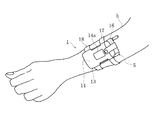
図1に示す携帯無線装置用ホルダー1(以下「ホルダー1」と記載する。)は、携帯電話機、PHP、トランシーバー等の携帯可能な無線装置(携帯無線装置)のためのホルダーである。トランシーバーとは、例えば、MCA(Multi-Channel Access radio system)無線のような業務用無線装置や、家庭用のいわゆるハンディタイプと呼ばれるような携帯可能な無線装置を広く含むものである。また、本実施例の説明においては、携帯無線装置の一例として携帯電話機5を用いて説明するが、上述の通り他の携帯可能な無線装置であればホルダー1を使用することができる。
【0017】
ホルダー1は、袋状で携帯電話機5を収納するポケット部13と、ポケット部13から突出し、ポケット部13を腕hに巻装するためのバンド部17,18とを備えている。ポケット部13の正面部14の中央付近には、携帯電話機5を収納した状態で、携帯電話機5に設けられた表示器の情報を目視可能な窓14aが設けられている。また、収納した携帯電話機5が、ポケット部13から飛び出さないようにするため、ポケット部13の背部15から正面部14に伸びる蓋部16を備え、携帯電話機5のポケット部13から突出する部分を覆っている。尚、本実施例の携帯電話機5は、厚板状の上筐体6と下筐体7とをヒンジ部8で折りたたみ自在に連結し、下筐体7の上端からアンテナ9が突出している。また、下筐体7の内部にバイブレータ10を備え、振動により着信を携帯者に報知する構造を有している。尚、携帯電話機5は、折りたたみ式のものに限らず、かまぼこ型の携帯電話機であってもよい。
【0018】
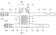
また、ポケット部13の背部15の両側には、バンド部17,18が設けられている。バンド部17とバンド部18は、図2に示すように、平行な2組のバンド部である、それぞれポケット部13の背部15の左右に伸びるバンド17a,17b,18a,18bからなる。バンド17a,18aの端部には、棒状の係止部材17e,18eを揺動可能に備えるバックル17d,18dが設けられている。また、バンド17b,18bの端部付近には、孔17c,18cが横一列に複数個穿設されている。尚、バンド部17,18の形状として、係止部材17e,18eを備えたバックル17d,18dに限られるものではなく、ポケット部13を腕に巻装することができれば、バンド17a,17b,18a,18bの端部にベルベットファスナを用いたものでもよく、また、1組のバンド17a,a7bだけでもよく、さらに、筒状のバンド部で、腕に挿嵌するような形状であってもよい。尚、ポケット部13及びバンド部17,18の材質は、布状で携帯電話機5を腕に巻装することができるものであればよく、皮、布、合成樹脂等である。
【0019】
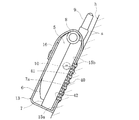
また、ポケット部13の背部15には、板状の振動伝達部材20が設けられている。振動伝達部材20は、板材であり、一方の面が無線装置当接面22となり、他方の面が腕当接面23となっている。また、腕当接面23側の角部は、全周で切り欠かれて鍔部21が形成され、図4に示すように、振動伝達部材20は縦断面凸状となっている。また、腕当接面23には、複数の凹部24が穿設されている。振動伝達部材20の材質は、携帯電話機5のバイブレータ10による振動を伝達しやすい金属、樹脂等である。
【0020】
振動伝達部材20は、ポケット部13の背面15の表面15a及び裏面15bを貫通するように配置され、鍔部21が裏面15bに密接して接着されている。そして、振動伝達部材20の腕当接面23が背面15の表面15aから突出すると共に、無線装置当接面22が背面15の裏面15bから突出している。尚、振動伝達部材20の固定は、接着に限られず縫製でもよく、固定方法が限定されるものではない。
【0021】
次に、本実施例におけるホルダー1の使用方法を説明する。まず、携帯電話機5を折りたたんだ状態で、ホルダー1のポケット部13に挿入する。そして、携帯電話機5が、ポケット部13から飛び出さないように蓋部16で、携帯電話機5の露出部分を押さえるようにする。次に、図1に示すように、ポケット部13の背部15を肌sに押し当てつつ、バンド部17,18を腕hに巻き付けた状態で、バンド17b,18bをバックル17d,18dに挿通し、孔17c,18cに係止部材17e,18eを掛けることにより、ホルダー1を腕hに巻装する。このとき、携帯電話機5の下筐体7の背面7aには振動伝達部材20の無線装置当接面22が密接しており、肌sには、振動伝達部材20の腕当接面23が密接している。尚、この状態で、携帯電話機5の操作者は、着信を待つことになる。
【0022】
携帯電話機5に着信があると、携帯電話機5のバイブレータ10が動作し、携帯電話機5が振動する。携帯電話機5の振動は、下筐体7を介して背面7aから振動伝達部材20の無線装置当接面22に伝わって振動伝達部材20が振動し、さらに腕当接面23から振動が肌sに伝わることになる。携帯電話機5の着信による振動が、振動伝達部材20を介して操作者の肌sに伝わることにより、操作者は着信を知ることになる。
【0023】
以上のように、本実施例のホルダー1によれば、振動を伝達可能で携帯無線装置である携帯電話機5と腕hとに当接する振動伝達部材20を介して、携帯電話機5の着信振動を確実に腕hに伝えることができ、操作者が振動の発生を着実に感じることができ、携帯電話機5の着信を容易に知ることができる。
【0024】
また、振動伝達部材20が板状で、無線装置当接面22が携帯電話機5と面接触すると共に、腕当接面23が腕hに面接触することから、携帯電話機5と腕hとに接する面積が広く、携帯電話機5の振動をより確実に操作者に伝えることができ、操作者はより一層確実に着信を知ることができる。
【0025】
また、ホルダー1の腕当接面23には、複数の凹部24が穿設されていることから、腕当接面23と腕hとの間で滑りが生じにくく、単に平面で接する場合に比べ携帯電話機5の振動をより確実に操作者に伝えることができ、操作者はより一層確実に着信を知ることができる。尚、振動伝達部材20の無線装置当接面22及び腕当接面23にどのような凹部又は凸部を設けるかは、収納する携帯無線装置の形状や大きさや腕の状態により適宜定めればよい。具体的には、図5に示すように、振動伝達部材26のように、無線装置当接面26aに球状の複数の凸部26bを設け、腕当接面26cには凹部26dを設けたり(図5(a))、振動伝達部材27のように、無線装置当接面27aと腕当接面27cの双方に凹部27b、27dを設けたり(図5(b))、腕当接面26cには凹部26dを設けたり(図5(a))、振動伝達部材28のように、無線装置当接面28aと腕当接面28cの双方に球状の複数の凸部28b、28dを設けたり(図5(c))してもよい。また、詳説した本実施例のように、一方の面に凸部又は凹部を設け、他方の面は平らなままにしておくこともできる。
【0026】
また、図6に示す振動伝達部材30のように、それぞれ大きさの異なる板材である無線装置側部材31と腕側部材32との2部材から構成させることも可能である。この振動伝達部材30では、無線装置側部材31と腕側部材32とに互いに硬さの異なる材質を用い、携帯無線装置及び腕のそれぞれに振動伝達に最適な硬度を選択することにより、携帯無線装置の振動をより確実に操作者に伝えることができ、操作者はより一層確実に着信を知ることができる。この場合、無線装置側部材31と腕側部材32とに硬度の異なる金属や樹脂を用いたり、いずれか一方を金属にして他方を樹脂にすることで硬度の異なる状態としてもよい。また、図6(b)に示すように、振動伝達部材20の無線装置当接面22に半球状の凸部材37を複数個貼付することにより、無線機当接面22に凸部を形成してもよく、この時、凸部材37の材質を振動伝達部材20とは硬度の異なるものを選択してもよい。
【0027】
尚、上述の振動伝達部材20は板状であるが、携帯無線装置の振動を伝達できる形状であれば板状に限られるものではなく、例えば、図7〜図10に示すような球体や棒材であっても構わない。図7及び図8に示す振動伝達部材40は、携帯無線装置用ホルダー2のポケット部15の背部15の表面15a及び裏面15bを貫通するように配置された球体である。そして、球面状の端部41が背面15の表面15aから突出すると共に、球面状の端部42が背面15の裏面15bから突出している。そして、振動伝達部材40の端部42が携帯電話機5に当接すると共に、端部41が腕hに当接し、振動伝達部材40を介して、携帯電話機5の着信振動が腕hに伝わることになる。振動伝達部材40が複数の球体からなることで、球面状である端部41が腕hに食い込むように当接することになり、単に平面で接する場合に比べ携帯電話機5の振動をより確実に操作者に伝えることができ、操作者はより一層確実に着信を知ることができる。
【0028】
また、図9及び図10に示す振動伝達部材45は、携帯無線装置用ホルダー3のポケット部15の背部15の表面15a及び裏面15bを貫通するように配置された棒材である。そして、一直線状に伸びる端部46が背面15の表面15aから突出すると共に、一直線状に伸びる端部47が背面15の裏面15bから突出している。そして、振動伝達部材45の端部47が携帯電話機5に当接すると共に、端部46が腕hに当接し、振動伝達部材45を介して、携帯電話機5の着信振動が腕hに伝わることになる。振動伝達部材45が棒材であることから、腕に食い込みやすく、単に平面で接する場合に比べ携帯電話機5の振動をより確実に操作者に伝えることができ、操作者はより一層確実に着信を知ることができる。
【0029】
尚、上述の振動伝達部材の材質として、金属としては、例えば、アルミニウム、チタン、鉄、銅、金、銀、白金、ニッケル、亜鉛、錫等が使用可能であり、これらの合金及びこれらとマグネシウム、コバルト、バナジウム等との合金であってもよい。また、セラミック素材や合成樹脂であってもよい。合成樹脂としては、例えば、シリコン樹脂、スチレン・ブタジエン樹脂、ブタジエン樹脂、イソプレン樹脂、クロロプレン樹脂、ウレタン樹脂、水酸化ニトリル樹脂、アクリル樹脂、アビクロロヒドリン樹脂、プロピレンオキサイド樹脂、エチレンアクリル樹脂、熱可塑性エラストマー(スチレン系、オレフィン系、ウレタン系、ポリエステル系、ポリアミド系、ポリブイタジエン系、塩化ビニル系、フッ素系等)等が使用可能である。
【0030】
また、銅、銀、錫等の金属や、これら金属、窒化珪素、炭化珪素を含むセラミック、樹脂等を用いることにより、振動伝達部材が電磁波遮断機能を有することになる。尚、電磁波とは、電界及び磁界の振動によって定められる、電荷の振動によって生じる放射エネルギーであり、電磁波遮断機能とは、電磁波の伝搬を断つ機能である。また、振動伝達部材に電磁波遮断機能を有するシートを貼付したり、電磁波遮断剤を塗布してもよい。振動伝達部材が電磁波遮断機能を有することにより、携帯電話機5が発する電磁波の人体に対する影響を軽減することができる。尚、振動伝達部材に電磁波遮断機能を備えさせる方法としては、上述の方法に限られるものではない。
【0031】
また、上述の振動伝達部材の材質として、金、銀、白銀、亜鉛、酸化チタン等の金属や、これら金属を含むセラミックス、樹脂等を用いることにより、振動伝達部材が抗菌機能を有することになる。尚、抗菌機能とは、菌の増殖を抑制する機能である。また、抗菌機能を有するシートを貼付したり、抗菌剤を塗布してもよい。振動伝達部材が抗菌機能を有することにより、振動伝達部材が直接肌sに当接しても、不衛生になりにくく、肌sへの影響を抑えることができる。尚、振動伝達部材に抗菌機能を備えさせる方法としては、上述の方法に限られるものではない。
【0032】
また、上述の振動伝達部材の材質として、導電性樹脂や界面活性剤を含む樹脂等を用いることにより、振動伝達部材が帯電防止機能を有することになる。尚、帯電防止機能とは、静電気の発生を抑える機能である。また、振動伝達部材に帯電防止機能を有するシートを貼付したり、帯電防止剤を塗布してもよい。振動伝達部材が帯電防止機能を有することにより、携帯無線装置用ホルダーと腕hとの間での静電気の発生を抑え、静電気により不快感が生じるのを防止することができる。尚、振動伝達部材に帯電防止機能を備えさせる方法としては、上述の方法に限られるものではない。
【0033】
【発明の効果】
請求項1の発明によれば、振動を伝達可能で携帯無線装置と腕とに直接当接する振動伝達部材を介して、携帯無線装置の振動を直接に且つ確実に腕に伝えることができ、携帯無線装置の着信を容易に知ることができる。更に、前記腕当接面に、凹部又は凸部を備えることにより、滑りが生じにくく、単に平面で接する場合に比べ携帯無線装置の振動をより確実に操作者に伝えることができ、操作者はより一層確実に着信を知ることができると共に、振動伝達部材が腕当接面に全面的に密着しないので、腕当接面の通気性が良く、衛生上好ましい。
【0034】
請求項2の発明によれば、携帯無線装置に当接する無線装置当接面と、腕に当接する腕当接面とを有する板材であることから、携帯無線装置と腕とに接する面積が広く、携帯無線装置の振動をより確実に操作者に伝えることができ、操作者はより一層確実に着信を知ることができる。
【0036】
請求項3の発明によれば、振動伝達部材が複数の球体からなることから、球面が腕に食い込むように当接することになり、単に平面で接する場合に比べ携帯無線装置の振動をより確実に操作者に伝えることができ、操作者はより一層確実に着信を知ることができる。
【0039】
請求項4の発明によれば、振動伝達部材が電磁波遮断機能を有することから、携帯無線装置が発する電磁波の人体に対する影響を軽減することができる。
【0040】
請求項5の発明によれば、振動伝達部材が抗菌機能を有することから、振動伝達部材が直接肌に当接しても、不衛生になりにくく、肌への影響を抑えることができる。
【0041】
請求項6の発明によれば、振動伝達部材が帯電防止機能を有することから、携帯無線装置用ホルダーと腕との間での静電気の発生を抑え、静電気により不快感が生じるのを防止することができる。
【図面の簡単な説明】
【図1】本発明に係る携帯無線装置用ホルダーの一例を示す斜視図である。
【図2】同携帯無線装置用ホルダーの背面図である。
【図3】図2の振動伝達部材の斜視図である。
【図4】図2のIV−IV線で携帯無線装置用ホルダーを破断した断面図である。
【図5】図2に示す振動伝達部材の他の形状を示す断面図である。
【図6】図2に示す振動伝達部材のさらに他の形状を示す断面図である。
【図7】振動伝達部材が球状である携帯無線装置用ホルダーの一例を示す背面図である。
【図8】図7のVIII−VIII線で携帯無線装置用ホルダーを破断した断面図である。
【図9】振動伝達部材が棒状である携帯無線装置用ホルダーの一例を示す背面図である。
【図10】図9のX−X線で携帯無線装置用ホルダーを破断した断面図である。
【符号の説明】
1〜3・・・・・・・・携帯無線装置用ホルダー(ホルダー)
5・・・・・・・・・・携帯電話機
13・・・・・・・・・ポケット部
15・・・・・・・・・背部
17,18・・・・・・バンド部
20,26〜28・・・振動伝達部材
21・・・・・・・・・鍔部
22・・・・・・・・・無線装置当接面
23・・・・・・・・・腕当接面
24・・・・・・・・・凹部
26b・・・・・・・・凸部
31・・・・・・・・・無線装置側部材
32・・・・・・・・・腕側部材
30,35・・・・・・振動伝達部材
40,45・・・・・・振動伝達部材[0001]
BACKGROUND OF THE INVENTION
The present invention relates to a portable wireless device holder for portable wireless devices such as mobile phones, PHPs, and transceivers.
[0002]
[Prior art]
A portable wireless device holder (hereinafter referred to as “holder”) for a portable wireless device such as a conventional mobile phone, PHP, or transceiver, which holds the portable wireless device on an arm, for example, There are some which are shown in Patent Document 1 and
[0003]
[Patent Document 1]
JP 2001-161424 A [Patent Document 2]
Design Registration No. 1143941 Publication [0004]
[Problems to be solved by the invention]
However, in the conventional portable wireless device holder, there is a cloth or leather pocket portion that easily absorbs vibration between the portable wireless device and the arm, and the incoming vibration of the portable wireless device is not easily transmitted to the arm. For this reason, there are often situations where the operator is unaware of incoming calls.
[0005]
The present invention has been made in view of such circumstances, and can reliably transmit the vibration of the portable wireless device to the arm, and the operator can easily and reliably know the incoming call of the portable wireless device. It is to provide a holder for a wireless device.
[0006]
[Means for Solving the Problems]
The holder for a portable wireless device according to claim 1, wherein a vibration transmitting member capable of transmitting vibration is formed from a back surface and a back surface constituting the back portion of the pocket portion so that the portable wireless device and the arm are in direct contact with each other. By projecting and disposing, the vibration of the portable wireless device is directly transmitted to the arm via the vibration transmitting member, while a concave or convex portion is provided on the arm contact surface that contacts the arm of the vibration transmitting member. It is characterized by having.
[0007]
The portable wireless device holder according to
The holder for a portable wireless device according to claim 3 is characterized in that the vibration transmitting member is composed of a plurality of spheres.
[0012]
The portable wireless device holder according to claim 4 is characterized in that the vibration transmitting member has an electromagnetic wave shielding function. The electromagnetic wave is radiant energy generated by the vibration of electric charges determined by the vibration of the electric field and the magnetic field, and the electromagnetic wave blocking function is a function of cutting off the propagation of the electromagnetic wave.
[0013]
The portable wireless device holder according to
[0014]
The portable wireless device holder according to
[0015]
DETAILED DESCRIPTION OF THE INVENTION
Hereinafter, embodiments of the present invention will be specifically described with reference to the drawings. FIG. 1 is a perspective view showing an example of a portable wireless device holder according to the present invention. 2 is a rear view of the portable wireless device holder, FIG. 3 is a perspective view of the vibration transmitting member of FIG. 2, and a sectional view of the portable wireless device holder taken along line IV-IV in FIG.
[0016]
A portable wireless device holder 1 (hereinafter referred to as “holder 1”) shown in FIG. 1 is a holder for portable wireless devices (portable wireless devices) such as a mobile phone, PHP, and transceiver. The transceiver widely includes, for example, a commercial radio device such as MCA (Multi-Channel Access radio system) radio and a portable radio device called a so-called handy type for home use. In the description of the present embodiment, the
[0017]
The holder 1 includes a
[0018]
[0019]
Further, a plate-like
[0020]
The
[0021]
Next, the usage method of the holder 1 in a present Example is demonstrated. First, the
[0022]
When the
[0023]
As described above, according to the holder 1 of this embodiment, the incoming vibration of the
[0024]
In addition, since the
[0025]
In addition, since the
[0026]
Further, like the
[0027]
The
[0028]
Moreover, the
[0029]
In addition, as a material of the above-mentioned vibration transmission member, as a metal, for example, aluminum, titanium, iron, copper, gold, silver, platinum, nickel, zinc, tin, and the like can be used. These alloys and these and magnesium Further, it may be an alloy with cobalt, vanadium or the like. Further, it may be a ceramic material or a synthetic resin. Synthetic resins include, for example, silicon resin, styrene / butadiene resin, butadiene resin, isoprene resin, chloroprene resin, urethane resin, nitrile hydroxide resin, acrylic resin, abichlorohydrin resin, propylene oxide resin, ethylene acrylic resin, heat Plastic elastomers (styrene-based, olefin-based, urethane-based, polyester-based, polyamide-based, polybutadiene-based, vinyl chloride-based, fluorine-based, etc.) can be used.
[0030]
In addition, by using a metal such as copper, silver, or tin, or a ceramic, resin, or the like containing these metals, silicon nitride, or silicon carbide, the vibration transmitting member has an electromagnetic wave shielding function. The electromagnetic wave is radiant energy generated by the vibration of electric charges determined by the vibration of the electric field and the magnetic field, and the electromagnetic wave blocking function is a function of cutting off the propagation of the electromagnetic wave. In addition, a sheet having an electromagnetic wave blocking function may be attached to the vibration transmitting member, or an electromagnetic wave blocking agent may be applied. Since the vibration transmitting member has an electromagnetic wave shielding function, the influence of the electromagnetic wave emitted by the
[0031]
Further, by using a metal such as gold, silver, white silver, zinc, titanium oxide, ceramics, resin, or the like containing these metals as the material of the above-described vibration transmission member, the vibration transmission member has an antibacterial function. . The antibacterial function is a function that suppresses the growth of bacteria. Further, a sheet having an antibacterial function may be attached or an antibacterial agent may be applied. Since the vibration transmitting member has an antibacterial function, even if the vibration transmitting member directly contacts the skin s, it is difficult to become unsanitary and the influence on the skin s can be suppressed. The method for providing the vibration transmitting member with the antibacterial function is not limited to the method described above.
[0032]
Further, by using a conductive resin, a resin containing a surfactant, or the like as the material of the above-described vibration transmission member, the vibration transmission member has an antistatic function. The antistatic function is a function for suppressing the generation of static electricity. Further, a sheet having an antistatic function may be attached to the vibration transmitting member, or an antistatic agent may be applied. Since the vibration transmitting member has an antistatic function, generation of static electricity between the portable wireless device holder and the arm h can be suppressed, and discomfort caused by static electricity can be prevented. The method for providing the vibration transmitting member with the antistatic function is not limited to the above method.
[0033]
【The invention's effect】
According to the first aspect of the present invention, the vibration of the portable wireless device can be directly and reliably transmitted to the arm via the vibration transmitting member capable of transmitting vibration and directly contacting the portable wireless device and the arm. An incoming call of a wireless device can be easily known. Furthermore, by providing the arm contact surface with a concave portion or a convex portion, it is difficult for slippage to occur, and the vibration of the portable wireless device can be transmitted to the operator more reliably than in the case of simply contacting with a flat surface. The incoming call can be known more reliably, and the vibration transmitting member does not fully adhere to the arm contact surface. Therefore, the air permeability of the arm contact surface is good, which is preferable in terms of hygiene.
[0034]
According to the invention of
[0036]
According to the invention of claim 3 , since the vibration transmitting member is composed of a plurality of spheres, the spherical surface comes into contact with the arm so that the vibration of the portable wireless device is more reliably compared to the case of simply contacting with a flat surface. The operator can be notified, and the operator can know the incoming call more reliably.
[0039]
According to the invention of claim 4 , since the vibration transmitting member has an electromagnetic wave shielding function, it is possible to reduce the influence of the electromagnetic wave emitted by the portable wireless device on the human body.
[0040]
According to the invention of
[0041]
According to the sixth aspect of the present invention, since the vibration transmitting member has an antistatic function, generation of static electricity between the portable wireless device holder and the arm is suppressed, and discomfort caused by static electricity is prevented. Can do.
[Brief description of the drawings]
FIG. 1 is a perspective view showing an example of a portable wireless device holder according to the present invention.
FIG. 2 is a rear view of the portable wireless device holder.
3 is a perspective view of the vibration transmission member of FIG. 2;
4 is a cross-sectional view of the portable wireless device holder taken along line IV-IV in FIG. 2. FIG.
5 is a cross-sectional view showing another shape of the vibration transmitting member shown in FIG. 2;
6 is a cross-sectional view showing still another shape of the vibration transmitting member shown in FIG. 2. FIG.
FIG. 7 is a rear view showing an example of a portable wireless device holder in which a vibration transmitting member is spherical.
8 is a cross-sectional view of the portable wireless device holder taken along line VIII-VIII in FIG.
FIG. 9 is a rear view showing an example of a portable wireless device holder in which the vibration transmitting member is rod-shaped.
10 is a cross-sectional view of the portable wireless device holder taken along line XX of FIG.
[Explanation of symbols]
1-3 ... Holder for portable wireless device (holder)
5 ...
Claims (6)
該振動を伝達可能な振動伝達部材が、該携帯無線装置と該腕とに直接当接するように該ポケット部の背部を構成する背面の表面及び裏面から突出させて配設することにより該振動伝達部材を介して該携帯無線装置の該振動を該腕に直接伝える一方、前記振動伝達部材の前記腕に当接する腕当接面に凹部又は凸部を備えたことを特徴とする携帯無線装置用ホルダー。In a portable wireless device holder having a pocket portion for storing a portable wireless device having a function of notifying an incoming call by vibration, and a band portion for winding the pocket portion around an arm,
The vibration transmitting member capable of transmitting the vibration is disposed so as to protrude from the front surface and the back surface constituting the back portion of the pocket portion so as to directly contact the portable wireless device and the arm. A portable wireless device characterized in that the vibration of the portable wireless device is directly transmitted to the arm through a member, and a concave or convex portion is provided on an arm contact surface that contacts the arm of the vibration transmitting member. holder.
Priority Applications (2)
| Application Number | Priority Date | Filing Date | Title |
|---|---|---|---|
| JP2002294760A JP3784362B2 (en) | 2002-10-08 | 2002-10-08 | Holder for portable wireless device |
| US10/680,906 US7243824B2 (en) | 2002-10-08 | 2003-10-08 | Holder for a portable wireless instrument |
Applications Claiming Priority (1)
| Application Number | Priority Date | Filing Date | Title |
|---|---|---|---|
| JP2002294760A JP3784362B2 (en) | 2002-10-08 | 2002-10-08 | Holder for portable wireless device |
Publications (2)
| Publication Number | Publication Date |
|---|---|
| JP2004134848A JP2004134848A (en) | 2004-04-30 |
| JP3784362B2 true JP3784362B2 (en) | 2006-06-07 |
Family
ID=32285203
Family Applications (1)
| Application Number | Title | Priority Date | Filing Date |
|---|---|---|---|
| JP2002294760A Expired - Fee Related JP3784362B2 (en) | 2002-10-08 | 2002-10-08 | Holder for portable wireless device |
Country Status (2)
| Country | Link |
|---|---|
| US (1) | US7243824B2 (en) |
| JP (1) | JP3784362B2 (en) |
Families Citing this family (54)
| Publication number | Priority date | Publication date | Assignee | Title |
|---|---|---|---|---|
| US20040259506A1 (en) * | 2003-06-18 | 2004-12-23 | Jany-Yee Hsu | Walkie talkie which vibrates when receiving incoming control signals |
| US20060237496A1 (en) * | 2005-04-25 | 2006-10-26 | Brennan Tasha N | Perfecthings |
| US20070061945A1 (en) * | 2005-09-08 | 2007-03-22 | Davis Margaret Y | Phone sock; a carrying devise worn on the forearm or ankle for cellular telephones |
| TWM300470U (en) * | 2005-11-03 | 2006-11-11 | Yi-Yi Chen | Sports-type wrist mobile cover |
| USD710598S1 (en) * | 2006-08-24 | 2014-08-12 | Mark Edward Morgan | Armband |
| US20080073400A1 (en) * | 2006-09-26 | 2008-03-27 | Built Ny, Inc. | Carrying pocket apparatus |
| US20080180214A1 (en) * | 2007-01-26 | 2008-07-31 | S2S Design | Protective pager sleeve |
| US20080190974A1 (en) * | 2007-02-12 | 2008-08-14 | Jeffrey Finn | Wearable tissue holder |
| CN101267719A (en) * | 2007-03-14 | 2008-09-17 | 鸿富锦精密工业(深圳)有限公司 | Portable electronic device shell |
| US20090039121A1 (en) * | 2007-08-09 | 2009-02-12 | Joseph Leo Paul | Cell phone bracelet / anklet |
| US8140131B1 (en) | 2008-06-16 | 2012-03-20 | Leo Green | Systems and methods for holding mobile electronic devices |
| USD677252S1 (en) | 2009-09-01 | 2013-03-05 | Lawrence M. Baum | Flexible garment for supporting a small portable electronic device |
| USD667172S1 (en) | 2009-09-01 | 2012-09-11 | Baum Lawrence M | Flexible garment for supporting a small portable electronic device |
| USD729790S1 (en) | 2009-09-01 | 2015-05-19 | Lawrence M Baum | Flexible garment with symmetrical left and right thumb openings |
| US8197005B2 (en) | 2008-09-03 | 2012-06-12 | Thorley Industries Llc | Infant care apparatus |
| US20100155438A1 (en) * | 2008-12-18 | 2010-06-24 | Halpin Design, Llc | Armband carrier for a personal media player |
| US20100301079A1 (en) * | 2009-05-26 | 2010-12-02 | Tanya John | Multifunctional bag |
| US8016492B2 (en) * | 2009-06-16 | 2011-09-13 | Colin James Pyle | Wrist or arm strap with hinged mount for camera |
| US20110049206A1 (en) * | 2009-09-02 | 2011-03-03 | Su-Chang Liao | Tie-able securing device for bicycle |
| US8317067B2 (en) * | 2009-10-07 | 2012-11-27 | Lewis Charles A | Device holder with magnetic retainer |
| US8279589B2 (en) * | 2010-02-01 | 2012-10-02 | Christine Hana Kim | Apparatus and method for data entry from a removable portable device cover |
| GB2480685B (en) * | 2010-05-28 | 2016-07-13 | Jaguar Land Rover Ltd | Improvements in or relating to vehicle access |
| ITBO20100388A1 (en) * | 2010-06-17 | 2011-12-18 | Massimo Moretti | NEURO LINGUISTIC PROGRAMMER |
| US20120152990A1 (en) * | 2010-12-15 | 2012-06-21 | Kulas Charles J | Thigh-mounted device holder |
| US9101184B2 (en) | 2011-01-05 | 2015-08-11 | Wimo Labs LLC | Electronic device casing |
| US9690258B2 (en) | 2011-01-05 | 2017-06-27 | Wimo Labs LLC | Electronic device casing |
| US8967437B2 (en) * | 2011-01-05 | 2015-03-03 | Wimo Labs LLC | Electronic device holder |
| US20120217274A1 (en) * | 2011-02-28 | 2012-08-30 | Gregory Cipes | Novel enhanced hands-free personal item carrying devices, systems, methods, and accoutrements |
| US9545146B1 (en) | 2011-03-03 | 2017-01-17 | Charles E. King | Carrier for electronic mobile devices |
| US10159328B1 (en) * | 2011-06-17 | 2018-12-25 | Blue Force Gear, Inc. | Load carrier systems and associated manufacturing methods |
| US9144168B2 (en) | 2012-03-08 | 2015-09-22 | The United States Of America, As Represented By The Secretary Of The Air Force | Appendage-mounted display apparatus |
| US20130270129A1 (en) * | 2012-04-17 | 2013-10-17 | August A. JOHNSON | Multi-Functional Pouch for Transporting and/or Suspending an Electronic Device |
| GB2502351A (en) * | 2012-05-23 | 2013-11-27 | Sanseva Ltd | A housing for an electronic device comprising cleaning material |
| EP3626097A1 (en) | 2013-03-15 | 2020-03-25 | Apple Inc. | Attachment apparatuses and associated methods of use and manufacture |
| US20150090750A1 (en) * | 2013-09-27 | 2015-04-02 | Robert Coleman | Forearm Magazine Holder |
| KR102205421B1 (en) | 2013-12-04 | 2021-01-20 | 삼성전자주식회사 | Wearable device and method for providing message of wearable device |
| CN103976544A (en) * | 2014-06-04 | 2014-08-13 | 南京际华三五二一特种装备有限公司 | Walky-talky bag |
| US10016029B2 (en) | 2014-08-09 | 2018-07-10 | Apple Inc. | Attachment systems for electronic devices |
| US10085523B2 (en) | 2014-08-11 | 2018-10-02 | Apple Inc. | Attachment system for an electronic device |
| US10184506B2 (en) | 2014-08-11 | 2019-01-22 | Apple Inc. | Captive elements of an attachment system |
| US10182623B2 (en) | 2014-08-11 | 2019-01-22 | Apple Inc. | Consumer product attachment systems having locking or expansion characteristics |
| US20160106201A1 (en) * | 2014-10-17 | 2016-04-21 | Biowerx, LLC | Smartphone armlet |
| US20160169648A1 (en) * | 2014-12-12 | 2016-06-16 | Dwain Singleton | Ammunition Carrying Apparatus |
| US9743731B2 (en) | 2014-12-18 | 2017-08-29 | Hand Held Products, Inc. | Wearable sled system for a mobile computer device |
| US9949537B2 (en) | 2015-03-06 | 2018-04-24 | Apple Inc. | Clasp mechanism for wrist-worn devices |
| US10154725B2 (en) | 2015-08-24 | 2018-12-18 | Thomas Lavin | Thigh mounted holder |
| US10064460B2 (en) | 2015-09-30 | 2018-09-04 | Apple Inc. | Frictional stabilization of band and securement mechanism |
| US10219591B2 (en) | 2016-03-21 | 2019-03-05 | Apple Inc. | Attachment system for an electronic device |
| US20170280862A1 (en) * | 2016-04-01 | 2017-10-05 | Matthew A. BLACKWOOD | Method, device and kit for securing cell phone in a pocket during activity |
| US10149518B1 (en) | 2016-08-08 | 2018-12-11 | Apple Inc. | Clasp assembly for a wearable device |
| USD841638S1 (en) | 2017-08-22 | 2019-02-26 | Eljon Jackson | Wrist worn phone holder |
| USD895934S1 (en) | 2018-03-28 | 2020-09-15 | Peter A. Ott | Wearable holder for items |
| USD861331S1 (en) * | 2018-07-13 | 2019-10-01 | Kwame Appiah | Mobile phone case |
| KR102151793B1 (en) * | 2019-06-13 | 2020-09-03 | 이종윤 | Mobile phone case with secondary battery fixing function |
Family Cites Families (22)
| Publication number | Priority date | Publication date | Assignee | Title |
|---|---|---|---|---|
| US3710784A (en) * | 1972-04-03 | 1973-01-16 | C Taylor | Massaging device |
| US4101861A (en) * | 1976-03-15 | 1978-07-18 | Texas Instruments Incorporated | Thermostatic switch and method of assembly |
| US4135653A (en) * | 1977-01-07 | 1979-01-23 | Sieloff Norman T | Armband assembly for carrying a portable radio |
| US4500019A (en) * | 1983-06-23 | 1985-02-19 | Curley Jr John J | Carrier for portable audio devices |
| US4754901A (en) * | 1984-11-19 | 1988-07-05 | Novi, Inc. | Stereophonic audio equipment carrier |
| US4771927A (en) * | 1986-11-24 | 1988-09-20 | Ventura Mario A | Cordless phone holder |
| US4798539A (en) * | 1987-03-26 | 1989-01-17 | Verlyn Henry | Prenatal learning device and method |
| US5327886A (en) * | 1992-08-18 | 1994-07-12 | Chiu Cheng Pang | Electronic massage device with cold/hot compress function |
| US5257729A (en) * | 1992-09-24 | 1993-11-02 | Silvernail Mark C | Tool holder |
| AU4413796A (en) * | 1994-12-05 | 1996-06-26 | Daniel S. Kline | Posture training device |
| JPH09331160A (en) * | 1996-06-12 | 1997-12-22 | Oki Electric Ind Co Ltd | Cell cover for portable equipment |
| JP3366649B2 (en) * | 1996-09-27 | 2003-01-14 | 日本写真印刷株式会社 | Mobile phone top lid and method of manufacturing the mobile phone top lid |
| JPH10210120A (en) | 1997-01-17 | 1998-08-07 | Mitsubishi Electric Corp | Incoming call delivery structure for portable telephone set |
| JP3019216B2 (en) * | 1998-01-20 | 2000-03-13 | 株式会社神奈川縫製商会 | Cell phone cases |
| US6550655B2 (en) * | 1999-03-31 | 2003-04-22 | Shirley Warner | Securing device for personal pagers |
| JP2001161424A (en) | 1999-12-13 | 2001-06-19 | Masaru Kaneko | Portable telephone bag |
| US6934517B2 (en) * | 2000-03-03 | 2005-08-23 | Kabushiki Kaisha Kanagawa Houseishoukai | Cellular phone holder |
| JP2002125282A (en) * | 2000-10-12 | 2002-04-26 | Eager:Kk | Holding tool for semiconductor acoustic equipment |
| JP2003087864A (en) * | 2001-09-13 | 2003-03-20 | Nec Tokin Corp | Calling device for mobile terminal communication |
| JP2003204810A (en) * | 2002-01-10 | 2003-07-22 | Kawamura Mitsue | Character design arm band |
| US20030222109A1 (en) * | 2002-03-07 | 2003-12-04 | Ran Weiss | Device for carrying portable equipment |
| US6880737B2 (en) * | 2002-10-25 | 2005-04-19 | Edward Bauer | Cell phone holster subsidiary strap and holder |
-
2002
- 2002-10-08 JP JP2002294760A patent/JP3784362B2/en not_active Expired - Fee Related
-
2003
- 2003-10-08 US US10/680,906 patent/US7243824B2/en not_active Expired - Fee Related
Also Published As
| Publication number | Publication date |
|---|---|
| JP2004134848A (en) | 2004-04-30 |
| US20040094584A1 (en) | 2004-05-20 |
| US7243824B2 (en) | 2007-07-17 |
Similar Documents
| Publication | Publication Date | Title |
|---|---|---|
| JP3784362B2 (en) | Holder for portable wireless device | |
| US10469640B2 (en) | Mobile accessory system | |
| US20080051138A1 (en) | Cellular telephone personal digital assistant, and pager unit with capability of short range radio frequency transmissions | |
| JP4231525B2 (en) | Communication device using bone conduction speaker | |
| EP2259556B1 (en) | Audio headset | |
| US8421607B2 (en) | Personal alert device | |
| JP3831190B2 (en) | Actuator support device and body-worn type transmission / reception device including the actuator support device | |
| JP3062727U (en) | Mobile phone belt | |
| JPS6156524A (en) | Portable radio equipment | |
| JPH11331017A (en) | Portable mobile communication terminal | |
| JP2004165985A (en) | Mobile telephone cover | |
| JPH10224439A (en) | Portable radio unit | |
| JP2002135020A (en) | Antenna function improving tool and portable telephone case equipped with the same | |
| EP1021025A1 (en) | Hand-holdable radio communication device | |
| JP2002171112A (en) | Portable telephone | |
| JP3792443B2 (en) | Vibrating structure of display screen in electronic equipment | |
| JP3108227U (en) | Foldable mobile phone case | |
| JP3091668B2 (en) | Mobile phone | |
| JP2002095521A (en) | Strap having antenna function for cellular phone | |
| JP3072445U (en) | Neck-mounted wireless microphone | |
| JP3054887U (en) | A bag having an incoming call notification function for a mobile phone, and a bag shoulder strap having an incoming call notification function for a mobile phone | |
| JP2006086564A (en) | Mobile communication apparatus | |
| JP3017538U (en) | Mobile phone incoming notification device | |
| JP3461787B2 (en) | Mobile phone call alert function bag | |
| JP2002111821A (en) | Arm portable telephone |
Legal Events
| Date | Code | Title | Description |
|---|---|---|---|
| A977 | Report on retrieval |
Free format text: JAPANESE INTERMEDIATE CODE: A971007 Effective date: 20050331 |
|
| A131 | Notification of reasons for refusal |
Free format text: JAPANESE INTERMEDIATE CODE: A131 Effective date: 20050412 |
|
| A521 | Request for written amendment filed |
Free format text: JAPANESE INTERMEDIATE CODE: A523 Effective date: 20050613 |
|
| A02 | Decision of refusal |
Free format text: JAPANESE INTERMEDIATE CODE: A02 Effective date: 20050823 |
|
| A521 | Request for written amendment filed |
Free format text: JAPANESE INTERMEDIATE CODE: A523 Effective date: 20051024 |
|
| A911 | Transfer to examiner for re-examination before appeal (zenchi) |
Free format text: JAPANESE INTERMEDIATE CODE: A911 Effective date: 20051102 |
|
| A131 | Notification of reasons for refusal |
Free format text: JAPANESE INTERMEDIATE CODE: A131 Effective date: 20051213 |
|
| A521 | Request for written amendment filed |
Free format text: JAPANESE INTERMEDIATE CODE: A523 Effective date: 20060206 |
|
| TRDD | Decision of grant or rejection written | ||
| A01 | Written decision to grant a patent or to grant a registration (utility model) |
Free format text: JAPANESE INTERMEDIATE CODE: A01 Effective date: 20060307 |
|
| A61 | First payment of annual fees (during grant procedure) |
Free format text: JAPANESE INTERMEDIATE CODE: A61 Effective date: 20060314 |
|
| R150 | Certificate of patent or registration of utility model |
Free format text: JAPANESE INTERMEDIATE CODE: R150 |
|
| FPAY | Renewal fee payment (event date is renewal date of database) |
Free format text: PAYMENT UNTIL: 20100324 Year of fee payment: 4 |
|
| FPAY | Renewal fee payment (event date is renewal date of database) |
Free format text: PAYMENT UNTIL: 20100324 Year of fee payment: 4 |
|
| FPAY | Renewal fee payment (event date is renewal date of database) |
Free format text: PAYMENT UNTIL: 20110324 Year of fee payment: 5 |
|
| LAPS | Cancellation because of no payment of annual fees |