JP3784247B2 - Fundus camera - Google Patents
Fundus camera Download PDFInfo
- Publication number
- JP3784247B2 JP3784247B2 JP2000268428A JP2000268428A JP3784247B2 JP 3784247 B2 JP3784247 B2 JP 3784247B2 JP 2000268428 A JP2000268428 A JP 2000268428A JP 2000268428 A JP2000268428 A JP 2000268428A JP 3784247 B2 JP3784247 B2 JP 3784247B2
- Authority
- JP
- Japan
- Prior art keywords
- fixation target
- fundus
- image
- mark
- display
- Prior art date
- Legal status (The legal status is an assumption and is not a legal conclusion. Google has not performed a legal analysis and makes no representation as to the accuracy of the status listed.)
- Expired - Fee Related
Links
Images


Classifications
-
- A—HUMAN NECESSITIES
- A61—MEDICAL OR VETERINARY SCIENCE; HYGIENE
- A61B—DIAGNOSIS; SURGERY; IDENTIFICATION
- A61B3/00—Apparatus for testing the eyes; Instruments for examining the eyes
- A61B3/10—Objective types, i.e. instruments for examining the eyes independent of the patients' perceptions or reactions
- A61B3/12—Objective types, i.e. instruments for examining the eyes independent of the patients' perceptions or reactions for looking at the eye fundus, e.g. ophthalmoscopes
-
- A—HUMAN NECESSITIES
- A61—MEDICAL OR VETERINARY SCIENCE; HYGIENE
- A61B—DIAGNOSIS; SURGERY; IDENTIFICATION
- A61B3/00—Apparatus for testing the eyes; Instruments for examining the eyes
- A61B3/10—Objective types, i.e. instruments for examining the eyes independent of the patients' perceptions or reactions
- A61B3/14—Arrangements specially adapted for eye photography
- A61B3/15—Arrangements specially adapted for eye photography with means for aligning, spacing or blocking spurious reflection ; with means for relaxing
- A61B3/152—Arrangements specially adapted for eye photography with means for aligning, spacing or blocking spurious reflection ; with means for relaxing for aligning
Landscapes
- Life Sciences & Earth Sciences (AREA)
- Health & Medical Sciences (AREA)
- Medical Informatics (AREA)
- Biophysics (AREA)
- Ophthalmology & Optometry (AREA)
- Engineering & Computer Science (AREA)
- Biomedical Technology (AREA)
- Heart & Thoracic Surgery (AREA)
- Physics & Mathematics (AREA)
- Molecular Biology (AREA)
- Surgery (AREA)
- Animal Behavior & Ethology (AREA)
- General Health & Medical Sciences (AREA)
- Public Health (AREA)
- Veterinary Medicine (AREA)
- Eye Examination Apparatus (AREA)
Description
【0001】
【発明の属する技術分野】
本発明は、被検眼眼底を撮影する眼底カメラに関する。
【0002】
【従来技術】
眼底カメラでは、眼底周辺部の撮影をも可能にするために、被検眼の視線を誘導する内部固視標(固視灯)を移動可能に構成したものが知られている。
【0003】
内部固視標を移動させる手段としては、点光源をレバー等で移動させる方式の他、点光源を所定位置に複数設けて選択的に順次点灯する方式等が幾つか提案されている。
【0004】
また、固視標の移動位置の確認には、観察光学系のカメラに固視標の点光源を光学的に合成し、観察モニタの画面上に眼底像と共に固視標像を表示させる方法が提案されている。
【0005】
【発明が解決しようとする課題】
しかし、上記従来技術の点光源をレバー等で移動させる方式では、観察モニタの観察によって固視標の位置を確認するが、例えば、眼底周辺部を60度毎に分割した6枚の撮影画像を必要とする検査の場合には、各撮影目的の位置に固視標を合せ難い。
【0006】
一方、複数の点光源を選択的に点灯する方式では、点灯位置の座標を予め決めておくことで撮影目的の位置に固視標移動が可能になるものの、定まった位置以外での撮影に対する自由度が少ない。
【0007】
本発明は、上記従来技術に鑑み、固視標移動の自由度を確保しつつ、撮影目的位置への固視標の移動を的確に行える眼底カメラを提供することを技術課題とする。
【0008】
【課題を解決するための手段】
上記課題を解決するために、本発明は以下のような構成を備えることを特徴とする。
【0009】
(1) 観察用照明光に照明された被検眼眼底を対物レンズを介して撮像する撮像素子と該撮像された眼底像を表示する表示モニタとを持つ観察手段と、を有する被検眼眼底を撮影する眼底カメラにおいて、被検眼に前記対物レンズを介して視認させる固視標を呈示する固視標呈示手段と、前記固視標の呈示位置を任意の位置に移動させ被検眼の視線を誘導する固視標移動手段と、該固視標移動手段によって移動される固視標を前記眼底像と光学的又は電気的に合成して表示モニタに表示する合成手段と、予め定められた複数の眼底周辺部を含む部位を撮影するために、前記表示モニタ上の固視標の移動目標としてガイド指標マークをグラフィック表示し、固視標をガイド指標マークに合うように移動させることにより視線を誘導するガイド指標マーク形成手段と、を備えることを特徴とする。
(2) (1)の眼底カメラは、さらにガイド指標マークを前記表示モニタに形成するか否かを選択する選択手段を備えることを特徴とする。
(3) (1)の眼底カメラは、さらに撮影完了信号にしたがって、次の移動目標となるガイド指標マークの表示形態を変化させるか、又は固視標の移動位置を検知する検知手段による検知に基づいて撮影が終了した位置のガイド指標マークの表示形態を変化させるか、いずれかの表示手段を備えることを特徴とする。
【0014】
【発明の実施の形態】
以下、本発明の一実施形態を図面に基づいて説明する。図1は第1の実施形態である無散瞳タイプの眼底カメラの光学系概略図である。光学系は照明光学系1、撮影光学系2、観察光学系3、固視標呈示光学系35から大別構成される。
【0015】
<照明光学系> 観察用光源であるハロゲンランプ10から出射された光束は、コンデンサレンズ11、赤外光を透過する赤外フィルタ12を介して赤外光束とされた後、ハーフミラー15で反射され、リング状の開口を有するリングスリット16を照明する。また、撮影用光源であるフラッシュランプ13から出射される可視光束は、コンデンサレンズ14を介した後、、ハーフミラー15を透過して観察用の赤外光束と同軸に合成され、リングスリット16を照明する。
【0016】
リングスリット16からの光束は、リレーレンズ17a、ミラー18、中心部に小黒点を有する黒点板19、リレーレンズ17bを介して、穴開きミラー21の開口部近傍に中間像を形成し、撮影光学系2の光軸と同軸になるように穴開きミラー21の周辺面で反射される。穴開きミラー21で反射したリングスリット光束は、対物レンズ20により被検眼Eの瞳孔付近で一旦結像した後、拡散して被検眼眼底部を一様に照明する。
【0017】
<撮影光学系> 撮影光学系2は、対物レンズ20、撮影絞り22、光軸方向に移動可能なフォーカシングレンズ23、結像レンズ24、撮影用のカラーCCDカメラ26を備える。25は観察光学系用のリターンミラーで撮影時には破線で示した位置に退去する。眼底からの反射光束は、対物レンズ20により一旦眼底の中間像を結像した後、穴開きミラー21の開口部、撮影絞り22、フォーカシングレンズ23、結像レンズ24を介してCCDカメラ26に入射し、その撮像素子面上に眼底像を結像する。
【0018】
<観察光学系> 観察光学系3は、撮影光学系2の対物レンズ20から結像レンズ24までを共用し、撮影時以外は実線で示した位置にあるリターンミラー25で光路を変える。30はハーフミラーで反射の比率は透過より大きくされている。ハーフミラー30の反射方向光路にはリレーレンズ31、可視域から赤外域に感度を持つ観察用のCCDカメラ32が配置されている。リターンミラー25で反射された眼底からの赤外反射光束は、ハーフミラー30でさらに反射された後、リレーレンズ31を介してCCDカメラ32に入射し、その撮像素子面上に眼底像を結像する。CCDカメラ32の出力は白黒兼用のカラーモニタ50に接続されており、モニタ50の画面上に眼底像ERが映し出される。
【0019】
<固視標呈示光学系> 固視標呈示光学系35は、固視目標となる点光源36、リレーレンズ37を備え、ハーフミラー30を介してリターンミラー25から対物レンズ20までの観察光学系3の光路を共用する。点光源36はレバー40の操作により、被検眼眼底及びCCDカメラ32の撮像面と略共役な平面内で移動可能に構成されている。図1において、点光源36が取り付けられたレバー40には長穴40aが形成されており、レバー40はビス43等によって眼底カメラの筐体部45に摺動自在に保持されている。そして、レバー40の一部は筐体部45から突出しており、検者はレバー40を操作することで、被検眼の眼底(視線方向)を所望の撮影部位へ誘導できるようになっている。
【0020】
また、ハーフミラー30を挟んで観察光学系3が持つリレーレンズ31の反対方向には反射ミラー39が設けられている。この反射ミラー39はリレーレンズ31を介してCCDカメラ32の撮像面と略共役な位置で、且つリレーレンズ37を介して固視目標の点光源36と略共役な位置に設定されている。点光源36を点灯すると、その光束の一部はハーフミラー30で反射して反射ミラー39に向かい、反射ミラー39で反射して元の方向へ戻るが、一部はハーフミラー30を透過した後にリレーレンズ31によってCCDカメラ32の撮像面に結像される。これにより、モニタ50上には眼底像ERに固視標像36´が合成されて表示される。
【0021】
図2は、制御系の要部ブロック図を示す図である。CCDカメラ32及びCCDカメラ26の出力は画像処理部51に入力される。画像処理部51は、制御部55からの制御信号を受けて、固視標の移動位置をガイドするためのガイド指標100をグラフィックで生成し、これをCCDカメラ32からの眼底像と共にモニタ50に合成して表示する。また、CCDカメラ26により撮影された眼底像は画像処理部51が持つ画像メモリ52に記憶された後、画像処理部51からの出力が切換えられ、モニタ50にはCCDカメラ26によるカラーの撮影画像が表示される。
【0022】
制御部55には撮影モードの切換えスイッチ56a等を持つスイッチ部56、画像記憶部57、撮影スイッチ58が接続されている。また、制御部55には外部コンピュータ60が接続可能で、画像記憶部57に記憶した画像データを転送出力できる。
【0023】
以上のような構成において、その動作を説明する。まず、任意の位置へ固視標を移動する場合について説明する。
【0024】
ハロゲンランプ10の点灯により、赤外光で照明された被検眼像は観察光学系3のCCDカメラ32に結像し、その像がモニタ50に映し出される。検者はモニタ50の表示を観察して、被検眼に対する眼底カメラ本体の位置調整を行う。また、フォーカシングレンズ23を移動してピント合わせを行う。固視目標の点光源36を点灯すると、その光束はリレーレンズ37、ハーフミラー30、リターンミラー25、結像レンズ24、フォーカシングレンズ23、撮影絞り22、穴開きミラー21の開口、対物レンズ20を通過して被検眼眼底に集光し、被検者は点光源36を固視標として視認する。これにより被検眼の視線が誘導される。
【0025】
また、ハーフミラー30で一部反射した点光源36の光束はミラー39で反射され、その反射光はハーフミラー30、リレーレンズ31を経てCCDカメラ32の撮像面に結像される。モニタ50の画面上には、被検眼の眼底像ER及び固視標像36´が映し出される。
【0026】
検者は、モニタ50の眼底像と固視標像36´を観察しながら、レバー40を操作して点光源36を任意の位置に移動し、所望部位が観察できるようにする。撮影位置が決定したら撮影スイッチ58を押して撮影を実行する。
【0027】
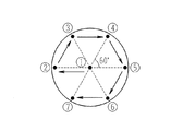
次に、図3に示すように、後極部中心の眼底画像111と、その周辺部を60度毎に分割した6枚の眼底画像112〜117を必要とする場合について説明する。このような眼底画像は、例えば、糖尿病性網膜症の検診に必要とされる。図4は、図3の各画像を得るために、モニタ画面上で固視標像36´を中心部から周辺部(円周の略60度分割)の計7個所に移動させて撮影する順番を示したものである。
【0028】
撮影に際しては、ガイド指標を表示するモードをスイッチ56aで選択する。このモードを選択すると、眼底像及び固視標像36´が映し出されるモニタ50上には、固視標の移動位置をガイドするガイド指標100として、中心を示す十字マーク101と円周を60度毎に分割した6本の周辺ラインマーク102〜107がグラフィックで合成されて表示される(図2参照)。
【0029】
検者はモニタ50に表示されたガイド指標100に従って固視標である点光源36を移動する。まず、1枚目の撮影として後極部中心の眼底画像111を得るために、固視標像36´が十字マーク101の表示位置の中心に来るようにレバー40を操作して点光源36を移動する。点光源36の移動により被検眼の視線を誘導したなら、撮影スイッチ58を押して眼底撮影像を得る。制御部55は撮影スイッチ58からのトリガ信号が入力されると、リターンミラー25を光路外へ退避させると共に、フラッシュランプ13を発光させて被検眼眼底を可視光で照明する。眼底からの可視の反射光は撮影光学系2の光路を辿って撮影用CCDカメラ26に入射し、眼底画像が得られる。
【0030】
CCDカメラ26の撮影像が画像メモリ52に記憶されると、画像処理部51によってモニタ50の画面は観察用画面から撮影画像の画面に切換えられ、画像メモリ52に記憶された静止画像が表示される。検者はこの撮影画像を確認し、良好であれば画像記憶スイッチ56bを押して、次の部位の撮影に移る。画像記憶スイッチ56bが押されると、画像メモリ52に記憶された画像は画像記憶部57に転送されて保存される。撮影画像が良好でない場合は、検者はキャンセルスイッチ56cを押すことで撮影をやり直す。
【0031】
スイッチ56b又は56cが押されると、モニタ50の表示は観察画像に切換えられ、ガイド指標100が観察像に重ねて再び表示される。
【0032】
検者は2枚目の撮影として周辺部の眼底画像112を得るために、固視標像36´が周辺ラインマーク102の表示位置に来るようにレバー40を操作して点光源36を移動して撮影を行う。以後、同様に周辺ラインマーク103、104、105、107の表示位置に固視標像36´が来るように点光源36を移動して撮影を行うことで、図2の眼底画像113、114、115、116、117が得られる。このとき、本実施形態の固視標呈示は固視標を任意に移動する方式であるので、固視標の呈示位置を選択的に切換える方式に比べ、被検者の視線を固視標の移動に追従させ易い。
【0033】
上記のガイド指標100に従った撮影においては、撮影の順番に応じてガイド指標の各マークの表示形態を変化させると、予定する撮影が分かり易くなる。例えば、上記の順番で固視標像36´を移動して撮影するものとした場合、画像処理部51は初めに十字マーク101を点滅表示させる。画像記憶スイッチ56bが押されることで撮影完了の信号が入力されたら、画像処理部51は次の撮影として周辺ラインマーク102を点滅表示させる。以後、画像処理部51は撮影完了の信号が入力される毎に周辺ラインマーク103〜107まで順次点滅させ、固視標移動の位置の変更を検者に知らせる。これにより、目的の撮影を漏れなく行うことができる。ガイド指標100の各マークは点滅表示に代えて、色を変化させても良いし、固視標を移動する位置のマークのみを表示しても良い。これらの場合、撮影の順番は制御部55内のメモリに予めプログラムされており、制御部55の指示によって画像処理部51がガイド指標100の表示形態を変化させる。
【0034】
また、ガイド指標100の各マークは、その部分の撮影が終了すると表示が消えるようにしたり、表示の色を変化させる等によって、撮影の順番を予め決めることなく撮影終了の部分を検者に知らせることができる。この場合、画像処理部51はCCDカメラ32に入射した固視標像36´の位置を検出することで、固視標の移動位置を検出する。固視標像36´の位置検出は、その大きさと光量から判断する(微弱な眼底反射光に比べて点光源36から入射する光量の方が大きいので、閾値レベルによって判断できる)。あるいは、ハーフミラー30と反射ミラー39の間に光束分離ミラーを設け、その分離方向にPSD等の2次元位置検出センサを位置させることで点光源36の移動位置を検知することができる。さらには、点光源36の近傍にその移動位置を検知するセンサを設け、固視標の移動位置を直接検知するようにしても良い。
【0035】
なお、固視標の移動位置の検出は厳密に行わなくとも、撮影部位に対応した位置関係が分かれば良いので、図5の点線で示すように7つに区分けされエリアで検出する。
【0036】
以上のようにガイド指標100の各マークに従って点光源36を移動することにより、目的とする位置又は所定角度での周辺部の撮影を容易に、且つ確実に実施することができる。
【0037】
また、こうして得た画像は的確な位置関係で視線が誘導された画像であるので、画像記憶部57に記憶した画像を外部コンピュータ60に転送し、外部コンピュータ60側で各画像を繋ぎ合わせてパノラマ画像を作成する上で、十分に良好なものとすることができる。
【0038】
図6は第2の実施形態として固視標呈示の変容例を示す部分概略構成図であり、先の実施形態に対して、任意の位置に移動させる固視標の点光源を液晶ディスプレイ70で実現した例である。液晶ディスプレイ70は被検眼眼底及びCCDカメラ32の撮像面と略共役な位置に配置され、その背後に光源71が配置されている。図7に示すように、液晶ディスプレイ70の開口部70aと遮光部70bの位置が制御部55によって制御され、光源71に照明される開口部70aが点光源とされる。そして、十字キー等の固視標移動スイッチ80を検者が操作することにより、点灯位置(開口部70aの位置)を任意の位置に移動できるように構成されている。
【0039】
また、先の実施形態ではモニタ50上に表示する固視標(固視標像36´)を光学的に合成する構成としたが、第2の実施形態では電気的に合成して表示するようにしている。すなわち、制御部55に接続された固視標移動スイッチ80を操作することにより開口部70aの位置が移動し、その位置情報は電気信号に変換されて制御部55によって得られ、モニタ50上には画像処理部51によって生成されキャラクタ70Cが位置情報に基づいて合成して表示される。そして、この第2の実施形態においても、ガイド指標100がモニタ50上に表示されるので、キャラクタ70Cが各マークに合うように固視標移動スイッチ80で固視標を移動させて撮影を実行する。
【0040】
【発明の効果】
以上説明したように、本発明によれば、固視標移動の自由度を確保しつつ、診断目的の撮影位置にも的確に固視標を移動して撮影が行える。
【図面の簡単な説明】
【図1】実施形態の眼底カメラの光学系概略図である。
【図2】制御系の要部ブロック図を示す図である。
【図3】後極部中心の眼底画像と、その周辺部を60度毎に分割した6枚の眼底画像を必要とする場合の説明図である。
【図4】図3の各画像を得るために、モニタ画面上で固視標像を移動させて撮影する順番を示した図である。
【図5】固視標の移動位置の検出を7つに区分けされたエリアで行う場合の例を示す図である。
【図6】固視標呈示の変容例を示す部分概略構成図である。
【図7】液晶ディスプレイにより固視標の形成を説明する図である。
【符号の説明】
10 ハロゲンランプ
20 対物レンズ20
26 CCDカメラ
32 CCDカメラ
36 点光源
36´ 固視標像
40 レバー
50 モニタ
51 画像処理部
55 制御部
56a スイッチ
100 ガイド指標[0001]
BACKGROUND OF THE INVENTION
The present invention relates to a fundus camera that photographs the fundus of a subject's eye.
[0002]
[Prior art]
In the fundus camera, there is known a fundus camera in which an internal fixation target (fixation lamp) that guides the line of sight of the eye to be examined is movable in order to enable photographing of the fundus periphery.
[0003]
As means for moving the internal fixation target, several methods have been proposed in which a plurality of point light sources are provided at a predetermined position and selectively turned on in addition to a method in which the point light source is moved by a lever or the like.
[0004]
In order to confirm the movement position of the fixation target, there is a method in which a fixation target point light source is optically combined with the camera of the observation optical system and the fixation target image is displayed together with the fundus image on the screen of the observation monitor. Proposed.
[0005]
[Problems to be solved by the invention]
However, in the method of moving the point light source of the above prior art with a lever or the like, the position of the fixation target is confirmed by observation with an observation monitor. For example, six photographed images obtained by dividing the fundus periphery every 60 degrees are obtained. In the case of necessary inspection, it is difficult to align the fixation target at the position for each photographing purpose.
[0006]
On the other hand, in the method of selectively lighting a plurality of point light sources, it is possible to move the fixation target to a shooting target position by determining the coordinates of the lighting position in advance, but it is free for shooting at a position other than a fixed position Less degree.
[0007]
In view of the above prior art, it is an object of the present invention to provide a fundus camera capable of accurately moving a fixation target to a shooting target position while ensuring a degree of freedom of movement of the fixation target.
[0008]
[Means for Solving the Problems]
In order to solve the above problems, the present invention is characterized by having the following configuration.
[0009]
(1) Photographing an eye fundus to be examined having an imaging device that images the fundus of the eye to be examined illuminated by the illumination light for observation through an objective lens and a display monitor for displaying the imaged fundus image In the fundus camera, the fixation target presenting means for presenting a fixation target to be visually recognized through the objective lens on the eye to be examined, and the visual indication of the eye to be examined are moved by moving the presentation position of the fixation target to an arbitrary position. Fixation target moving means, combining means for optically or electrically synthesizing the fixation target moved by the fixation target moving means with the fundus image and displaying it on a display monitor, and a plurality of predetermined fundus In order to image a region including a peripheral portion, a guide indicator mark is displayed in a graphic form as a target for moving the fixation target on the display monitor, and the fixation target is moved so as to match the guide indicator mark to guide the line of sight Guide finger A mark mark forming means.
(2) The fundus camera of (1) further includes selection means for selecting whether or not to form a guide index mark on the display monitor.
(3) The fundus camera of (1) further changes the display form of the guide index mark as the next movement target in accordance with the photographing completion signal, or detects by the detection means for detecting the movement position of the fixation target. Based on this, the display form of the guide index mark at the position where photographing has been completed is changed, or any display means is provided.
[0014]
DETAILED DESCRIPTION OF THE INVENTION
Hereinafter, an embodiment of the present invention will be described with reference to the drawings. FIG. 1 is a schematic diagram of an optical system of a non-mydriatic type fundus camera according to the first embodiment. The optical system is roughly divided into an illumination optical system 1, a photographing
[0015]
<Illumination Optical System> A light beam emitted from a
[0016]
The light flux from the
[0017]
<Photographing Optical System> The photographing
[0018]
<Observation Optical System> The observation
[0019]
<Fixation Target Presenting Optical System> The fixation target presenting
[0020]
A
[0021]
FIG. 2 is a block diagram showing a main part of the control system. Outputs from the
[0022]
Connected to the
[0023]
The operation of the above configuration will be described. First, a case where the fixation target is moved to an arbitrary position will be described.
[0024]
When the
[0025]
Further, the light beam of the point
[0026]
The examiner operates the
[0027]
Next, as shown in FIG. 3, a case will be described in which a
[0028]
At the time of shooting, a mode for displaying the guide index is selected by the
[0029]
The examiner moves the point
[0030]
When the captured image of the
[0031]
When the
[0032]
The examiner moves the point
[0033]
In shooting according to the
[0034]
Each mark of the
[0035]
Note that the movement position of the fixation target need not be strictly detected, but it is sufficient that the positional relationship corresponding to the imaging region is known. Therefore, as shown by the dotted line in FIG.
[0036]
As described above, by moving the point
[0037]
Further, since the image obtained in this way is an image in which the line of sight is guided with an accurate positional relationship, the image stored in the
[0038]
FIG. 6 is a partial schematic configuration diagram showing a modification example of fixation target presentation as the second embodiment. The
[0039]
In the previous embodiment, the fixation target (
[0040]
【The invention's effect】
As described above, according to the present invention, it is possible to perform imaging while accurately moving the fixation target to the imaging position for diagnostic purposes while ensuring the degree of freedom of movement of the fixation target.
[Brief description of the drawings]
FIG. 1 is a schematic diagram of an optical system of a fundus camera of an embodiment.
FIG. 2 is a block diagram showing a main part of a control system.
FIG. 3 is an explanatory diagram when a fundus image at the center of the posterior pole part and six fundus images obtained by dividing the peripheral part every 60 degrees are needed.
4 is a diagram illustrating an order in which a fixation target image is moved on a monitor screen to obtain each image of FIG. 3; FIG.
FIG. 5 is a diagram illustrating an example of a case where the movement position of a fixation target is detected in an area divided into seven areas.
FIG. 6 is a partial schematic configuration diagram showing a modification example of fixation target presentation.
FIG. 7 is a diagram illustrating formation of a fixation target by a liquid crystal display.
[Explanation of symbols]
10
26
Claims (3)
Priority Applications (4)
| Application Number | Priority Date | Filing Date | Title |
|---|---|---|---|
| JP2000268428A JP3784247B2 (en) | 2000-08-31 | 2000-08-31 | Fundus camera |
| EP01120480A EP1183992B1 (en) | 2000-08-31 | 2001-08-28 | Fundus camera |
| DE60115555T DE60115555T2 (en) | 2000-08-31 | 2001-08-28 | fundus camera |
| US09/940,582 US6968127B2 (en) | 2000-08-31 | 2001-08-29 | Fundus camera |
Applications Claiming Priority (1)
| Application Number | Priority Date | Filing Date | Title |
|---|---|---|---|
| JP2000268428A JP3784247B2 (en) | 2000-08-31 | 2000-08-31 | Fundus camera |
Publications (2)
| Publication Number | Publication Date |
|---|---|
| JP2002065610A JP2002065610A (en) | 2002-03-05 |
| JP3784247B2 true JP3784247B2 (en) | 2006-06-07 |
Family
ID=18755212
Family Applications (1)
| Application Number | Title | Priority Date | Filing Date |
|---|---|---|---|
| JP2000268428A Expired - Fee Related JP3784247B2 (en) | 2000-08-31 | 2000-08-31 | Fundus camera |
Country Status (4)
| Country | Link |
|---|---|
| US (1) | US6968127B2 (en) |
| EP (1) | EP1183992B1 (en) |
| JP (1) | JP3784247B2 (en) |
| DE (1) | DE60115555T2 (en) |
Families Citing this family (33)
| Publication number | Priority date | Publication date | Assignee | Title |
|---|---|---|---|---|
| US6637882B1 (en) | 1998-11-24 | 2003-10-28 | Welch Allyn, Inc. | Eye viewing device for retinal viewing through undilated pupil |
| WO2002053020A2 (en) * | 2001-01-03 | 2002-07-11 | Walthard Vilser | Device and method for imaging, stimulation, measurement and therapy, in particular for the eye |
| JP2002224038A (en) | 2001-01-31 | 2002-08-13 | Nidek Co Ltd | Fundus camera |
| JP3929721B2 (en) | 2001-05-25 | 2007-06-13 | 株式会社ニデック | Fundus camera |
| US6705726B2 (en) | 2002-02-20 | 2004-03-16 | Nidek Co., Ltd. | Instrument for eye examination and method |
| US20030157464A1 (en) * | 2002-02-20 | 2003-08-21 | Cesare Tanassi | Instrument for eye examination and method |
| JP2004024470A (en) | 2002-06-25 | 2004-01-29 | Canon Inc | Ophthalmic photographing apparatus |
| US6830336B2 (en) * | 2002-11-01 | 2004-12-14 | Inoveon Corporation | Automated generation of fundus images based on processing of acquired images |
| JP2004254945A (en) * | 2003-02-26 | 2004-09-16 | Nidek Co Ltd | Fundus camera |
| JP4138533B2 (en) | 2003-02-28 | 2008-08-27 | 株式会社ニデック | Fundus camera |
| US7369759B2 (en) * | 2003-03-27 | 2008-05-06 | Matsushita Electric Industrial Co., Ltd. | Eye image pickup apparatus, iris authentication apparatus and portable terminal device having iris authentication function |
| JP4047255B2 (en) * | 2003-09-25 | 2008-02-13 | 株式会社ニデック | Fundus camera |
| WO2005122874A1 (en) * | 2004-06-18 | 2005-12-29 | Lions Eye Institute Limited | Opthalmic camera and opthalmic camera adaptor |
| AU2005253648B2 (en) * | 2004-06-18 | 2011-12-01 | Lions Eye Institute Limited | Opthalmic camera and opthalmic camera adaptor |
| JP4628763B2 (en) * | 2004-12-01 | 2011-02-09 | 株式会社ニデック | Fundus camera |
| US7918559B2 (en) * | 2005-04-29 | 2011-04-05 | Novadaq Technologies Inc. | Choroid and retinal imaging and treatment system |
| JP4630126B2 (en) * | 2005-05-16 | 2011-02-09 | 株式会社トプコン | Ophthalmic optical characteristic measuring device |
| DE102006011624A1 (en) * | 2006-03-10 | 2007-09-13 | Carl Zeiss Meditec Ag | Device and method for the defined alignment of an eye |
| JP5179063B2 (en) * | 2007-01-06 | 2013-04-10 | 株式会社ニデック | Ophthalmic equipment |
| JP4937792B2 (en) * | 2007-03-01 | 2012-05-23 | 株式会社ニデック | Fundus camera |
| JP5094233B2 (en) * | 2007-06-22 | 2012-12-12 | キヤノン株式会社 | Ophthalmic photographing apparatus and ophthalmic photographing system |
| DE102010014744B4 (en) * | 2010-04-13 | 2013-07-11 | Siemens Aktiengesellschaft | Apparatus and method for projecting information onto an object in thermographic surveys |
| CN102885612A (en) * | 2012-02-14 | 2013-01-23 | 苏州微清医疗器械有限公司 | Fundus imaging equipment for clinical diagnosis |
| JP5179675B2 (en) * | 2012-02-20 | 2013-04-10 | 株式会社ニデック | Ophthalmic equipment |
| JP5389220B2 (en) * | 2012-04-26 | 2014-01-15 | キヤノン株式会社 | Ophthalmic imaging equipment |
| CN103908223B (en) * | 2013-01-08 | 2016-08-24 | 荣晶生物科技股份有限公司 | Image acquiring device and acquisition methods |
| US8985771B2 (en) * | 2013-01-08 | 2015-03-24 | Altek Corporation | Image capturing apparatus and capturing method |
| TWI561210B (en) * | 2013-01-08 | 2016-12-11 | Altek Biotechnology Corp | Image capturing apparatus and capturing method |
| JP6463047B2 (en) * | 2014-09-05 | 2019-01-30 | キヤノン株式会社 | Ophthalmic device and method of operating an ophthalmic device |
| JP6884995B2 (en) * | 2016-06-03 | 2021-06-09 | 株式会社ニデック | Ophthalmologic imaging equipment and image processing program |
| WO2019089647A1 (en) | 2017-10-30 | 2019-05-09 | Verily Life Sciences Llc | Active visual alignment stimuli in fundus photography |
| US11147441B2 (en) | 2018-01-16 | 2021-10-19 | Welch Allyn, Inc. | Physical assessment device |
| CN111557639A (en) * | 2020-06-05 | 2020-08-21 | 上海鹰瞳医疗科技有限公司 | Fundus inspection system |
Family Cites Families (15)
| Publication number | Priority date | Publication date | Assignee | Title |
|---|---|---|---|---|
| US4068932A (en) | 1975-05-23 | 1978-01-17 | Canon Kabushiki Kaisha | Optical instrument for examining the eye fundus |
| IT1207998B (en) | 1986-05-14 | 1989-06-01 | Ausimont Spa | CROSS-LINKING OF EPOXY RESINS BY MULTIPURPOSE PERFLUOROPOLYETERS. |
| US5037194A (en) * | 1988-05-31 | 1991-08-06 | Canon Kabushiki Kaisha | Ophthalmologic apparatus and method of compounding the image of an eye to be examined |
| JP3379592B2 (en) * | 1993-07-26 | 2003-02-24 | 株式会社トプコン | Fundus camera |
| JP3408308B2 (en) * | 1994-02-02 | 2003-05-19 | 株式会社ニデック | Fundus camera |
| JP3465997B2 (en) * | 1995-04-28 | 2003-11-10 | 株式会社ニデック | Fundus camera |
| JP3576671B2 (en) | 1995-12-22 | 2004-10-13 | キヤノン株式会社 | Ophthalmic imaging equipment |
| JPH09276232A (en) | 1996-04-12 | 1997-10-28 | Nikon Corp | Fundus camera |
| US6082859A (en) * | 1997-09-17 | 2000-07-04 | Kabushiki Kaisha Topcon | Ophthalmological photographing apparatus |
| JP3809267B2 (en) | 1997-12-16 | 2006-08-16 | キヤノン株式会社 | Ophthalmic imaging equipment |
| JP4011731B2 (en) | 1998-05-01 | 2007-11-21 | キヤノン株式会社 | Ophthalmic equipment |
| IL125483A (en) * | 1998-07-23 | 2006-08-20 | Talia Technologia Ltd | System and method for acquiring, analyzing and imaging of three dimensional retinal data |
| JP4265833B2 (en) | 1998-12-28 | 2009-05-20 | 株式会社トプコン | Ophthalmic imaging equipment |
| JP4231146B2 (en) * | 1999-04-05 | 2009-02-25 | 株式会社トプコン | Fundus camera |
| JP3718098B2 (en) * | 2000-03-22 | 2005-11-16 | 株式会社ニデック | Fundus camera |
-
2000
- 2000-08-31 JP JP2000268428A patent/JP3784247B2/en not_active Expired - Fee Related
-
2001
- 2001-08-28 DE DE60115555T patent/DE60115555T2/en not_active Expired - Lifetime
- 2001-08-28 EP EP01120480A patent/EP1183992B1/en not_active Expired - Lifetime
- 2001-08-29 US US09/940,582 patent/US6968127B2/en not_active Expired - Fee Related
Also Published As
| Publication number | Publication date |
|---|---|
| EP1183992B1 (en) | 2005-12-07 |
| US6968127B2 (en) | 2005-11-22 |
| DE60115555D1 (en) | 2006-01-12 |
| DE60115555T2 (en) | 2006-08-17 |
| EP1183992A3 (en) | 2003-01-02 |
| JP2002065610A (en) | 2002-03-05 |
| EP1183992A2 (en) | 2002-03-06 |
| US20020025145A1 (en) | 2002-02-28 |
Similar Documents
| Publication | Publication Date | Title |
|---|---|---|
| JP3784247B2 (en) | Fundus camera | |
| US6636696B2 (en) | Fundus camera | |
| JP3660118B2 (en) | Anterior segment imaging device | |
| JP3929721B2 (en) | Fundus camera | |
| JP5772117B2 (en) | Fundus photographing device | |
| EP0643941B1 (en) | Apparatus for obtaining images of cornea cells | |
| JP2007202724A (en) | Retinal camera | |
| JP5862142B2 (en) | Corneal endothelial cell imaging device | |
| JP4886388B2 (en) | Fundus camera | |
| JP5772101B2 (en) | Fundus photographing device | |
| JPH114808A (en) | Fundus camera | |
| JP5545982B2 (en) | Fundus camera | |
| JP2000005131A (en) | Fundus camera | |
| JP4774305B2 (en) | Fundus camera | |
| JP6008023B2 (en) | Corneal endothelial cell imaging device | |
| JP2008006103A (en) | Fundus camera | |
| JP4080183B2 (en) | Anterior segment imaging device | |
| JP2004254945A (en) | Fundus camera | |
| JP4164199B2 (en) | Ophthalmic measuring device | |
| JPH0788086A (en) | Device to photograph cornea cell | |
| JP4520244B2 (en) | Fundus camera | |
| JP4774317B2 (en) | Fundus camera | |
| JP4492854B2 (en) | Fundus camera | |
| JP5787060B2 (en) | Fundus photographing device | |
| JP2011030689A (en) | Fundus photographing system and method for processing three-dimensional fundus image |
Legal Events
| Date | Code | Title | Description |
|---|---|---|---|
| A621 | Written request for application examination |
Free format text: JAPANESE INTERMEDIATE CODE: A621 Effective date: 20040702 |
|
| A977 | Report on retrieval |
Free format text: JAPANESE INTERMEDIATE CODE: A971007 Effective date: 20050616 |
|
| A131 | Notification of reasons for refusal |
Free format text: JAPANESE INTERMEDIATE CODE: A131 Effective date: 20051005 |
|
| A521 | Request for written amendment filed |
Free format text: JAPANESE INTERMEDIATE CODE: A523 Effective date: 20051202 |
|
| TRDD | Decision of grant or rejection written | ||
| A01 | Written decision to grant a patent or to grant a registration (utility model) |
Free format text: JAPANESE INTERMEDIATE CODE: A01 Effective date: 20060222 |
|
| A61 | First payment of annual fees (during grant procedure) |
Free format text: JAPANESE INTERMEDIATE CODE: A61 Effective date: 20060314 |
|
| R150 | Certificate of patent or registration of utility model |
Free format text: JAPANESE INTERMEDIATE CODE: R150 |
|
| LAPS | Cancellation because of no payment of annual fees |