JP3780094B2 - Print control system, print controller, image server, information processing apparatus and method, and storage medium storing computer-readable program - Google Patents
Print control system, print controller, image server, information processing apparatus and method, and storage medium storing computer-readable program Download PDFInfo
- Publication number
- JP3780094B2 JP3780094B2 JP11325898A JP11325898A JP3780094B2 JP 3780094 B2 JP3780094 B2 JP 3780094B2 JP 11325898 A JP11325898 A JP 11325898A JP 11325898 A JP11325898 A JP 11325898A JP 3780094 B2 JP3780094 B2 JP 3780094B2
- Authority
- JP
- Japan
- Prior art keywords
- image
- server
- print server
- image data
- Prior art date
- Legal status (The legal status is an assumption and is not a legal conclusion. Google has not performed a legal analysis and makes no representation as to the accuracy of the status listed.)
- Expired - Fee Related
Links
- 238000000034 method Methods 0.000 title claims abstract description 85
- 230000010365 information processing Effects 0.000 title claims description 14
- 230000006870 function Effects 0.000 claims description 60
- 230000005540 biological transmission Effects 0.000 claims description 44
- 230000015572 biosynthetic process Effects 0.000 claims description 2
- 238000003786 synthesis reaction Methods 0.000 claims description 2
- 230000008569 process Effects 0.000 abstract description 59
- 239000000470 constituent Substances 0.000 abstract 1
- 238000010586 diagram Methods 0.000 description 44
- 238000011156 evaluation Methods 0.000 description 25
- 230000008859 change Effects 0.000 description 17
- 230000007246 mechanism Effects 0.000 description 11
- 230000004044 response Effects 0.000 description 5
- 238000006243 chemical reaction Methods 0.000 description 4
- 238000003745 diagnosis Methods 0.000 description 4
- 238000004140 cleaning Methods 0.000 description 3
- 230000008094 contradictory effect Effects 0.000 description 3
- 238000011084 recovery Methods 0.000 description 3
- 230000000694 effects Effects 0.000 description 2
- 239000004065 semiconductor Substances 0.000 description 2
- 230000009471 action Effects 0.000 description 1
- 230000006835 compression Effects 0.000 description 1
- 238000007906 compression Methods 0.000 description 1
- 238000001514 detection method Methods 0.000 description 1
- 238000003825 pressing Methods 0.000 description 1
- 230000009467 reduction Effects 0.000 description 1
- 230000008054 signal transmission Effects 0.000 description 1
- 238000005092 sublimation method Methods 0.000 description 1
Images


Classifications
-
- G—PHYSICS
- G06—COMPUTING; CALCULATING OR COUNTING
- G06F—ELECTRIC DIGITAL DATA PROCESSING
- G06F3/00—Input arrangements for transferring data to be processed into a form capable of being handled by the computer; Output arrangements for transferring data from processing unit to output unit, e.g. interface arrangements
- G06F3/12—Digital output to print unit, e.g. line printer, chain printer
- G06F3/1201—Dedicated interfaces to print systems
- G06F3/1202—Dedicated interfaces to print systems specifically adapted to achieve a particular effect
- G06F3/1203—Improving or facilitating administration, e.g. print management
- G06F3/1205—Improving or facilitating administration, e.g. print management resulting in increased flexibility in print job configuration, e.g. job settings, print requirements, job tickets
-
- G—PHYSICS
- G06—COMPUTING; CALCULATING OR COUNTING
- G06F—ELECTRIC DIGITAL DATA PROCESSING
- G06F3/00—Input arrangements for transferring data to be processed into a form capable of being handled by the computer; Output arrangements for transferring data from processing unit to output unit, e.g. interface arrangements
- G06F3/12—Digital output to print unit, e.g. line printer, chain printer
- G06F3/1201—Dedicated interfaces to print systems
- G06F3/1202—Dedicated interfaces to print systems specifically adapted to achieve a particular effect
- G06F3/1203—Improving or facilitating administration, e.g. print management
- G06F3/1208—Improving or facilitating administration, e.g. print management resulting in improved quality of the output result, e.g. print layout, colours, workflows, print preview
-
- G—PHYSICS
- G06—COMPUTING; CALCULATING OR COUNTING
- G06F—ELECTRIC DIGITAL DATA PROCESSING
- G06F3/00—Input arrangements for transferring data to be processed into a form capable of being handled by the computer; Output arrangements for transferring data from processing unit to output unit, e.g. interface arrangements
- G06F3/12—Digital output to print unit, e.g. line printer, chain printer
- G06F3/1201—Dedicated interfaces to print systems
- G06F3/1223—Dedicated interfaces to print systems specifically adapted to use a particular technique
- G06F3/1237—Print job management
- G06F3/1242—Image or content composition onto a page
-
- G—PHYSICS
- G06—COMPUTING; CALCULATING OR COUNTING
- G06F—ELECTRIC DIGITAL DATA PROCESSING
- G06F3/00—Input arrangements for transferring data to be processed into a form capable of being handled by the computer; Output arrangements for transferring data from processing unit to output unit, e.g. interface arrangements
- G06F3/12—Digital output to print unit, e.g. line printer, chain printer
- G06F3/1201—Dedicated interfaces to print systems
- G06F3/1223—Dedicated interfaces to print systems specifically adapted to use a particular technique
- G06F3/1237—Print job management
- G06F3/1253—Configuration of print job parameters, e.g. using UI at the client
-
- G—PHYSICS
- G06—COMPUTING; CALCULATING OR COUNTING
- G06F—ELECTRIC DIGITAL DATA PROCESSING
- G06F3/00—Input arrangements for transferring data to be processed into a form capable of being handled by the computer; Output arrangements for transferring data from processing unit to output unit, e.g. interface arrangements
- G06F3/12—Digital output to print unit, e.g. line printer, chain printer
- G06F3/1201—Dedicated interfaces to print systems
- G06F3/1278—Dedicated interfaces to print systems specifically adapted to adopt a particular infrastructure
- G06F3/1285—Remote printer device, e.g. being remote from client or server
- G06F3/1288—Remote printer device, e.g. being remote from client or server in client-server-printer device configuration
Abstract
Description
【0001】
【発明の属する技術分野】
本発明は複数の出力装置を用いて画像情報を最適な装置において出力することができる印刷制御システム、プリントコントローラ、イメージサーバ、情報処理装置及びその制御方法に関する。
【0002】
【従来の技術】
従来の技術では、インターネットやイントラネットなどのネットワークを用いることによって、特定のプリントサーバに対して遠隔地域の操作端末から画像データを送信し画像出力を依頼することができた。
【0003】
また、システム上に複数のプリントサーバを備えるような場合では、操作端末で画像出力を依頼する際に出力を実行するプリントサーバを指定することにより、要求するプリンタにおいて出力処理を実行することができた。
【0004】
【発明が解決しようとする課題】
前記従来技術では、遠隔地域への画像出力を依頼する際に、出力する全ての画像データを伝送させるために伝達経路(ネットワーク)を占有する必要があるため、画像データの伝送負荷が高くなり画像出力完了までに時間を要し、更に画像データ伝送に要する経費(回線の使用料など)も大きくなるという問題があった。
【0005】
また、画像出力情報をイメージ情報とイメージ以外の情報とに分類して個別に伝送することにより、伝送経路の負荷と伝送情報量を軽減させることは従来より可能だったが、伝送負荷の高いイメージ情報が伝達経路を介して伝送されることには変わりはないために、伝送情報量と経費の大幅な削減には至らなかった。
【0006】
更に、従来技術においては、画像出力を要請する出力装置の使用状況に関わらず、目的とする出力装置での出力を実行するため、システム全体での資源を有効に活用することができなかった。
【0007】
【課題を解決するための手段】
本発明によれば、画像出力のための画像送信に伴う伝送情報量と経費を大幅に削減させるために、イメージを含んだ画像出力情報のうちイメージ情報を予め前記イメージサーバに蓄積されているものを使用することを可能とした。
【0008】
また、画像出力を実施するプリントサーバをシステム全体の負荷状況や出力画像に要求される品質や機能に応じてプリントコントローラで自動的に判別することにより、システム内の資源を有効に活用することを可能とした。
【0009】
更に、画像出力を実施するプリントサーバを選択するための基準を、指定するための手段をシステム利用者の要求情報内に用いることにより、利用者の特異的要求に柔軟に応じて出力装置を選定することを可能とした。
【0010】
本発明は前記問題に鑑みてなされたものであり、本発明の印刷制御システムは、以下の構成からなる。
【0011】
即ち、画像データを印刷するための印刷制御システムにおいて、前記イメージサーバに蓄積された画像データを利用して画像データの高精細出力を制御するための複数のプリントサーバと、印刷に先だって、前記イメージサーバからの画像データを送信すべきプリントサーバの選択を各プリントサーバの選択を指示する情報とは異なる情報に基づいて行うプリントコントローラとを有したことを特徴とする。
【0012】
また、本発明の印刷制御システムは、以下の構成からなる。
【0013】
即ち、画像データを印刷するための印刷制御システムにおいて、画像データを蓄積しておくためのイメージサーバに蓄積された画像データを利用して画像データの出力を制御するための複数のプリントサーバと、前記画像データの印刷注文を受信する受信手段と、前記受信された印刷注文に前記プリントサーバの選択に関する指示情報が含まれているかどうか検知する検知手段と、前記指示情報が含まれていないと検知されれば、プリントサーバの実行条件が満足されることをチェックして、前記画像データの印刷処理を実行するプリントサーバを複数のプリントサーバの中から1つ指定するプリントコントローラとを有し、複数のパラメータを含む実行条件は、指示情報とは異なることを特徴とする。
【0032】
【発明の実施の形態】
〔第一実施例〕
<システム構成>
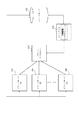
図1は、本発明の印刷制御が行われるシステム構成図である。
【0033】
図1中101は文書編集アプリケーションを含むクライアントコンピュータである。クライアントコンピュータ101は、文書編集アプリケーションの機能により、文字列、図形、イメージ等のデータを含む文書の作成機能、同編集機能、及び文書データのページ記述言語への変換機能を持っている。
【0034】
102はイメージサーバであり、タイルで分割管理されるイメージフォーマット(例えばフラッシュピックスフォーマット:登録商標)の画像データと分割管理されていない通常のイメージフォーマット(例えば、JPEGフォーマット)の画像データとを複数解像度保持し、ネットワークを介して画像ファイル内の指定された任意解像度イメージのイメージタイルデータを提供する。
【0035】
103はプリントコントローラであり、クライアントコンピュータ101からのページ記述言語で記述された印刷スクリプトと印刷オーダを受け取り、印刷オーダーを処理するプリントサーバを選択し、印刷スクリプトと印刷オーダーに基づく印刷依頼を送信する。
【0036】
104、105、106はプリントサーバであり、プリントコントローラ103からの印刷オーダーに応じて、画像データを取得し、印刷スクリプトに基づいて画像データを編集処理して印刷を行う。本実施例でいうプリントサーバとは、例えば編集用のPCと高詳細画像を印刷出力できるプリンタからなる装置である。本プリントサービスのシステムにおけるプリントサーバは、フィルムを現像してくれるプリントショップに設置されているものである。
【0037】
クライアントコンピュータ101、イメージサーバ102、プリントコントローラ103、プリントサーバ104、105、106はネットワーク等の信号伝達手段で相互に結合されている。本実施例における具体的な結合を説明すると、クライアントコンピュータ及びプリントサーバは、本印刷システムとインターネットを介して接続されており、ダイヤルアップ形式もしくは専用線のオンライン方式の接続方法である。プリントコントローラとイメージサーバは、専用線でインターネット接続されている。
【0038】
<イメージフォーマット>
図2は、本発明で使用される画像データの一つの実施例であるFlashPix(登録商標)のイメージフォーマットを説明する説明図である。イメージサーバ102には、ここで説明するイメージフォーマットのイメージファイルが複数存在している。もちろん後述するフラッシュピックスフォーマット以外のイメージファイルであっても本発明を適用できることは言うまでもない。フラッシュピックス以外の画像フォーマットとしては、ビットマップデータを始め、圧縮フォーマットとしてJPEG、TIF、ZIP等が存在し、どのフォーマットの画像データを用いても、本発明を適用できることは言うまでもない。
【0039】
図2中201はフラッシュピックスフォーマットのイメージファイルを示す。イメージファイル201は、解像度0から解像度nの複数の解像度のイメージを階層的に保持している。解像度は添え字の数値が小さいほど高解像度であること示す。解像度0が最も解像度が高く、添え字の数値が1増えると解像度は1/2になる。202、203、204はそれぞれ解像度0、解像度1、解像度nのイメージをあらわす。
【0040】
各解像度のイメージは固定画素数の正方形のイメージタイルに分割管理されている。205はイメージファイル201中の解像度0のイメージと、該イメージを構成するイメージタイルとの関係を示している。イメージタイル上に示された(X,Y)の形式のインデックスはイメージ中のイメージタイルを識別するためのイメージタイルIDである。
【0041】
イメージタイルの画素数は固定であるので、解像度が異なるイメージ間では同一の部分を示すイメージタイルの個数およびIDは異なる。例えば、同一の部分を表す解像度1でのイメージタイルの面積は、解像度0での同一の部分を表すイメージタイルの面積の4倍になる。このため解像度0でイメージタイルID(0,0)、(1,0)、(1,0)、(1,1)の4つのイメージタイルで示される領域は、解像度1ではイメージタイルID(0,0)の1つのイメージタイルで示される領域と等しくなる。
【0042】
前述したように本発明のイメージサーバは複数の解像度の画像データを持っているため、編集など低解像度の画像ですむ処理に低解像度のイメージを使用することができ、メモリ使用量の低減やデータ送信処理の高速化による操作性の向上などの効果がある。
【0043】
<スクリプト>
図3は、本発明で使用するページ記述言語で記述されたスクリプトの例の説明図である。
【0044】
図3中301は図2の解像度1のイメージ203とイメージタイルの関係を示す。
【0045】
302はクライアントコンピュータ101の文書編集アプリケーションで作成される文書を示す。
【0046】
303、304、305はそれぞれ文書302に含まれるイメージデータ、図形データ、文字列データを示す。
【0047】
306は文書302をクライアントコンピュータ101の文書編集アプリケーションでページ記述言語に変換したスクリプトである。
【0048】
クライアント101は、イメージサーバなどの画像データを記憶している外部装置から編集用の画像として低解像度の画像データを要求し、低解像度の画像データを取得する。そして、クライアント101の文書編集アプリケーションでの文書の編集では解像度1のイメージを使用することにより編集に必要なメモリ量を削減している。また、画像データをネットワーク経由で取得する場合にも送信されるデータ量が削減されるため効果がある。また、本実施例では、クライアント101とイメージサーバはダイヤルアップ形式のインターネットで接続しているので、高解像度の画像データを送受信すると、送受信に多くの時間を有してしまい、回線接続料が高くなりコストアップにつながってしまう。よって、本発明のように低解像度の画像データをインターネットで受信することにより接続時間が減少し、回線接続料が安くなるという効果も得られる。また、本実施の形態では、解像度1のイメージを使用したが、解像度2、3などのような更に低解像度のイメージを使用した方が、送信データ量が削減されるため効果的である。
【0049】
文書302中には解像度1のイメージ301のうちイメージタイルID(1,0)の部分だけが含まれている。文書302をスクリプト306に変換する時、イメージデータ303の部分は、データそのものを取り込むのではなく、イメージファイル201の存在する場所を示すイメージファイルID、解像度インデックス、イメージタイルIDを記述し、スクリプトを処理する時点でイメージデータを取り込む。これによりスクリプトのサイズを小さくすることが可能となり、ネットワーク経由の送信において負荷を軽減することができる。
【0050】
スクリプト306において、documentの後に続く数字は、ドキュメントIDを示しており、文書編集アプリケーションによりユニークにつけられる。pageの後の数字は、ページ数を示している。textの後に書かれているものは「Times New Roman」のフォントで48ポ、斜体、50、30の位置に「Flower」と文字を書くということを示している。circleというのは、円を描けという命令で、70、20の位置に半径10、太さ2という情報が記載されている。最後のimageとは、画像データがあるということを示しており、5、5の位置に「http://image.conon.co.jp/public/flower.fpx」というURLにある画像データの解像度1の(1、0)というタイルの画像が使用されていることを示している。
【0051】
このようにクライアント101の文書編集アプリケーションで編集した編集命令の履歴がスクリプト形式のファイルとして生成される。本実施例でいう編集とは、以下のような編集である。つまり、画像データ全体に対しての、モザイク処理、ぼかし処理、色変換(カラーバランス)、階調変換(グレイスケール処理を含む)等のことである。更に、写真の枠やテキストを挿入する枠等を示すテンプレート(イメージデータ)や、スタンプやイラストなどのデータを追加すること、図形の描画、テキストの挿入なども、本実施例でいう編集処理の定義に含まれるものである。このように定義される編集の履歴が編集情報として、スクリプト形式のデータがクライアント101で生成されるのである。
【0052】
上記説明したように、クライアント101は、ダイヤルアップ接続でインターネットを介してイメージサーバに低解像度の画像データを要求し、低解像度の画像データを受信する。そして、クライアント101内で低解像度の画像データを編集し、編集した履歴情報をスクリプト形式の編集情報として生成する。そして、編集情報をダイヤルアップ接続のインターネットを介してプリントコントローラに送信して印刷オーダーを出している。ユーザは、画像データを好きなように編集でき、かつ印刷オーダーを編集履歴として少ないデータ量として生成でき、編集される画像データのIDを含む編集情報を印刷オーダーとして送信するので、印刷オーダー時のインターネット接続時間が短くて済むのである。
【0053】
<プリントコントローラのブロック図>
図4はプリントコントローラのシステム構成を示すブロック図である。
【0054】
図4中1001は本装置全体の制御を司るCPUである。CPU1001は、制御手段として機能する。
【0055】
1002は一時記憶手段として機能するRAMである。RAM1002は、CPU1001の主メモリとして、及びROM1003に格納されている実行プログラムのワークエリアや一時待避領域として機能する。
【0056】
1003はCPU1001の動作処理手順を記憶しているROMである。ROM1003にはプリントサービスコントローラの機器制御を司るシステムプログラムを記録したプログラムROMと、システムを稼動するために必要な情報等が記憶されたデータROMがある。
【0057】
1004は、外部との送受信手段として機能するネットワークインターフェイス(Net−I/F)である。このネットワークインタフェース1004は、後述するプリントサーバとのデータ送信制御や、ユーザ端末と本システムを繋ぐためのネットワークシステム(インターネット等)とのデータ送信を行なうためのデータ制御や診断を行なう。
【0058】
1005は、表示用記憶手段として機能するビデオRAM(VRAM)である。このビデオRAM1005は、システムの稼動状態を示す表示手段としての機能を有するCRT1006の画面に表示される画像を展開し、その表示の制御を行う。
【0059】
1007はキーボードなどの外部入力装置からの入力信号を制御するためのキーボードコントローラある。1008は操作を受け付けるための外部入力装置であり、一般にはキーボードやポインティングデバイス(マウスなど)を示している。
【0060】
1009は記憶手段として機能するハードディスクドライブ(HDD)を示し、後述するアプリケーションプログラムや画像情報のデータ保存用に用いられる。
【0061】
1010は外部記憶手段として機能するフロッピーディスクなどのリムーバルディスクドライブ(FDD)を示し、後述するアプリケーションプログラムの媒体からの読み出しなどに用いられる。図6の処理フローで表されるプログラムをフロッピーディスク1010に記憶して、ハードディスクに格納しておいても本システムは実現可能である。
【0062】
1000は上述した各ユニット間を接続するためのI/Oバス(アドレスバス、データバスおよび制御バス)である。
【0063】
<プリントサーバのブロック図>
図5はプリントサーバ104〜106のシステム構成を示すブロック図である。
【0064】
図5中2001は本装置全体の制御を司るCPUである。
【0065】
2002は一時記憶手段として機能するRAMである。RAM2002は、CPU2001の主メモリとして、及びROM2003に格納されている実行プログラムのワークエリアや一時待避領域として機能する。
【0066】
2003はCPU2001の動作処理手順を記憶しているROMである。ROM2003にはプリントサーバの機器制御を司るシステムプログラムを記録したプログラムROMと、システムを稼動するために必要な情報等が記憶されたデータROMがある。
【0067】
2004は、外部との送受信手段として機能するネットワークインターフェイス(Net−I/F)である。ネットワークインタフェース2004は、プリントサービスコントローラとのデータ送信制御や、他のプリントサーバや画像サーバとの画像データ送信を行なうための制御や診断を行なう。
【0068】
2005は、表示用記憶手段として機能するビデオRAM(VRAM)である。ビデオRAM2005は、システムの稼動状態を示す表示手段の機能を有するCRT2006の画面に表示される画像を展開し、その表示の制御を行う。
【0069】
2007は、キーボードなどの外部入力装置からの入力信号を制御するためのキーボードコントローラある。2008は操作を受け付けるための外部入力装置であり、一般にはキーボードやポインティングデバイス(マウスなど)を示している。
【0070】
2009は、記憶手段として機能するハードディスクドライブ(HDD)を示し、後述するアプリケーションプログラムや画像情報のデータ保存用に用いられる。
【0071】
2010は、外部記憶手段として機能するフロッピーディスクなどのリムーバルディスクドライブ(FDD)を示し、後述するアプリケーションプログラムの媒体からの読み出しなどに用いられる。図10の処理フローで表されるプログラムをフロッピーディスク1010に記憶して、ハードディスクに格納しておいても本システムは実現可能である。
【0072】
2011はプリンタ制御部(PRTC)であり、プリンタ2012の制御と出力する画像の制御を行う。
【0073】
2012はプリントサーバで高詳細な画像データの印刷出力を行うための印字手段として機能するプリンタである。プリンタ2012は、一つのプリントサーバで複数のプリンタを接続することが可能となっている。
【0074】
2000は上述した各ユニット間を接続するためのI/Oバス(アドレスバス、データバスおよび制御バス)である。
【0075】
<動作説明>
まず、図3を用いて、本システムの全体的な動作説明を行う。
【0076】
ユーザは、クライアントコンピュータ101の文書作成アプリケーションの機能により、ダイヤルアップ接続のインターネットを介してイメージサーバ102からイメージファイル201中の解像度1のイメージ203中のイメージタイルID9003(1,0)のイメージデータ303を取得し文書302を作成する。
【0077】
ユーザがプリントサービスを要求する操作を実行すると、クライアントコンピュータ102の文書編集アプリケーションは文書302をスクリプト306に変換し、プリントオーダ情報を付加してプリントオーダファイルを作成し、ダイヤルアップ接続してインターネットを介してプリントコントローラ103に送る。プリントオーダ情報には住所、氏名、クレジットカード番号などの個人情報(#UserID)、印刷範囲(#PageRange)、印刷部数(#Copies)及び支払い方法(#Payment)などの印刷情報が含まれる。
【0078】
プリントコントローラ103では、後述するプリントサーバの決定手段により印刷を実行するプリントサーバ104を決定し、同サーバ104へスクリプト306に基づく印刷依頼を送信する。
【0079】
プリントサーバ104では受信したスクリプト306に基づく印刷依頼を解読し、該印刷依頼に示されるスクリプト内に記述された解像度のイメージデータもしくはイメージタイルデータ303をイメージサーバ102から取得し、スクリプトの他の画像情報(304、305)と、イメージデータもしくはイメージタイルデータ303により文書302の印刷画像を合成してプリンタ2012への印刷を実行する。
【0080】
<プリントコントローラでの処理>
図6は本発明におけるプリントコントローラでの処理の流れを説明するためのフロー図である。
【0081】
図中、S1でクライアントコンピュータ101の文書編集アプリケーションからプリントコントローラ103へ印刷オーダと印刷スクリプトが伝送されることにより、一連の処理が開始される。
【0082】
印刷オーダには図7で後述するフォーマットにより、出力を行なうプリントサーバを選定するための情報(出力指定情報)を含んでいるて、S2で印刷オーダから出力指定情報の解析を行なう。
【0083】
解析された出力指定情報の結果により、S3で必要に応じてプリントサーバ管理テーブルを更新する。
【0084】
プリントサーバ管理テーブルは、システム内に接続されているプリントサーバ(104、105、106)の状態を管理し、印刷オーダに応じて出力を実行するプリントサーバを決定するために使用するテーブルである。(詳細は図8で後述する。)
【0085】
S4で、同テーブル先頭に位置されるプリントサーバの稼働状態を確認し、そのプリントサーバが使用可能な状態であるか否かをS5で判定した後に、使用可能な状態であれば、S6でそのプリントサーバへ印刷オーダと印刷スクリプトを伝送して画像出力を指示する。
【0086】
S5の判定で、該当するプリントサーバが実行条件を満たしていないと判断された場合には、S7でプリントサーバ管理テーブルを修正および更新する。
【0087】
プリントサーバ管理テーブル更新の結果、S8で新たに実行可能なプリントサーバがあるかを判定し、存在すればS9でそのプリントサーバの状態を確認してS5へ戻る。
【0088】
S8で次のプリントサーバが見つからなければ、S10で依頼者にエラーを通知するなどの非常処理手段を行なった後に、一連の処理を終了する。
【0089】
<プリントサーバでの処理>
プリントサーバ104等は、上記プリントコントローラ103の処理によりプリントコントローラ103から伝送された印刷オーダと印刷スクリプトを含む印刷依頼により、出力画像を生成し、プリントサーバに接続されたプリンタ2012に対して画像の出力を実行する。
【0090】
伝送された印刷スクリプト中にイメージに関する情報が含まれている場合には、同情報に基づいて、イメージサーバ102より必要なイメージタイルを直接取得し、出力画像生成時にイメージタイルを含んだ画像を合成してプリンタ2012に出力する。
【0091】
このとき、使用したイメージデータ及びイメージタイルを一定期間プリントサーバのHDD2009に保存することにより、一定期間内に同じイメージデータ及びイメージタイルが使用された出力画像の印刷を指示された時に、同HDDに保存されたイメージデータ及びイメージタイルを使用することにより、イメージデータ及びイメージタイルを再びイメージサーバ102から伝送させる負荷を軽減することができる。
【0092】
<印刷オーダ>
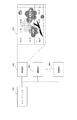
図7は本発明における、画像出力を依頼する依頼者の文書編集アプリケーションを含むクライアントコンピュータ101からプリントコントローラ103へ伝達される印刷オーダのフォーマットを示す摸式図である。
【0093】
図における401から411までの一連の情報が印刷に必要な情報として印刷スクリプトと共にプリントコントローラ103へ伝送される。
【0094】
図中401は個人識別情報長を示すパラメータであり、これに続く402の個人識別情報のデータ長(データサイズ)を示している。
【0095】
個人識別情報402は、画像出力の依頼主を確認するための情報であり、個人名、パスワードなどのID情報、課金管理に必要な情報等が含まれるが、本発明の内容には重要でないため、ここではその詳細には触れない。
【0096】
403以降は画像出力を実行するプリントサーバを選択するために必要となる情報である、出力指定情報である。
【0097】
403は出力指定パラメータの使用数を示す。この長さが0の場合には依頼者は特に出力するプリントサーバの指定は行なわないことになり、デフォルトのプリントサーバ(プリントコントローラ上のプリントサーバ管理テーブルで最上位にあるプリントサーバ)で出力されることになる。
【0098】
404、406、408、410は出力指定の基準となるパラメータであり、例えば、地理的な近さや画像品質などの、プリントサーバを決定するための要因を一意的に示すIDが与えられる。図では例として404ではパラメータ1に「地理的近さ」が、406ではパラメータ2に「出力時間」が、408ではパラメータ3に「印刷品質」が示されている。
【0099】
410はパラメータがN個用意されていることを示すものであり、そのため403の出力指定パラメータ数はNとなっている。
【0100】
また、405、407、409、411はそれぞれパラメータ1、パラメータ2、パラメータ3、パラメータNの優先度数を示すための数値(優先度)が示される。ここで、各パラメータの優先順位はデータ内での配置順序に依るものではなく、それぞれの優先度の大小により相対的に決定される。
【0101】
ただし優先度が等しい場合には、プリントコントローラ内での優先順位決定の手順に従って順位が決定されるため、本情報だけでは優先順位を判断することはできない。
【0102】
なお、プリントコントローラ103からプリントサーバ104等へ伝送する印刷オーダはに、出力指定情報は必要ないため必ずしも同情報は含まれない。
【0103】
<プリントサーバ管理テーブル>
図8は、プリントコントローラ103内で管理されているプリントサーバ管理テーブルのフォーマットを示すための摸式図である。
【0104】
本テーブルでは、システム内に接続されている全てのプリントサーバに関する、各パラメータの度数が記録されている。この度数の大小によって、プリントサーバの優劣が決定される。
【0105】
図中501は例として「プリントサーバ1」のパラメータ値を示す行であり、行中にパラメータ1、2、Nの度数が記録される。
【0106】
テーブル中の各列は各パラメータを意味し、図では例として、502、503、504がそれぞれ「パラメータ1」「パラメータ2」「パラメータN」を意味している。
【0107】
501と同様な行がプリントサーバの個数(図ではM個)用意されていて、505は「プリントサーバ2」の行を、506は「プリントサーバ3」の行を、507は「プリントサーバM」の行をそれぞれ示している。
【0108】
テーブル中には各プリントサーバとパラメータに応じた数値が記録されている。例えば508のP(1,1)は「プリントサーバ1」における「パラメータ1」の数値を示す値であり、509のP(M,N)は「プリントサーバM」における「パラメータN」の数値を示す値である。プリントサーバ間で、あるパラメータに関しての優劣を比較する時には、各列においてこの値の比較を行なう。
【0109】
本テーブルにおけるプリントサーバの行の順番は、画像出力を実行するプリントサーバの優劣の順番と一致するものとする。(即ち、図8では1、2、3…Nの順番が優先順ということになる。)そのため、各プリントサーバのパラメータに対する度数が変更された場合には、随時テーブルの行の順序が補正される。
【0110】
また、クライアントコンピュータ101から伝送される印刷オーダ中の出力指定情報(図7)で渡されるパラメータの優先度数に応じて各プリントサーバの優劣が変更および決定される。この場合にもテーブルの行の順序が再修正される。
【0111】
なお、本プリントサーバ管理テーブルは図4におけるプリントサーバのハードディスク1009に記憶され、RAM1002に展開されて使用される。
【0112】
<プリントサーバ管理テーブルの変更の例1>
図9は、図8で示したプリントサーバ管理テーブルが更新される状況を示すための摸式図である。
【0113】
図中601は更新前のプリントサーバ管理テーブルであり、602は更新後の同テーブルの状態を示している。
【0114】
603、604、605はそれぞれプリントサーバ1、2、3の状態を示すための行であり、606はパラメータ1の状態を示す列である。ここで、最上位にあるパラメータ1が最も優先度の高いパラメータとする。
【0115】
今、プリントサーバ1、2、3のパラメータ1に対する度数をそれぞれP(1,1)(607)、P(2,1)(608)、P(3,1)(609)、とすると、パラメータ1に対する優先順位を決定するために、これらの値の大小が比較される。
【0116】
例えば、
P(3,1) > P(1,1) > P(2,1) …(式1)
というような大小関係があった場合には、優先度に応じてテーブルが変更されて602のような605、603、604の順番に修正される。
【0117】
このように各プリントサーバの持つパラメータの度数の変化に応じてプリントサーバ管理テーブルは随時変更される。
【0118】
図10は、以上で説明したプリントサーバ管理テーブルが変更される処理の流れを示すためのフロー図である。
【0119】
図10で、S1で何らかの原因によりテーブルの変更の必要が発生する。例えば、図6のS3もしくはS7における処理である。
【0120】
S2で最上位のパラメータに対しての各プリントサーバの優先度を管理テーブル内の情報に基づいて比較する。
【0121】
S3で比較の結果管理テーブルに更新の必要が生じた場合は同テーブルを更新する。
【0122】
通常はこれでテーブルの更新は終了するべきだが、同一順位のプリントサーバが存在する場合のために、引続き以下の処理を行なう。
【0123】
S4で同一順位になったプリントサーバが存在するか否かをチェックする。もし同一順位のものが存在しなければ、処理を終了する。
【0124】
同一順位のサーバが存在した場合には、S5でまだ比較に使用していないパラメータが残っているかをチェックする。
【0125】
未使用のパラメータが残っていた場合には、S6でそのパラメータに基づいてのサーバの優先度の比較を行ない、S3に戻る。
【0126】
S5で、未使用のパラメータが残っていなかった場合には、それ以上は比較する術がないので、同一順位のサーバは更新前の順序のままでテーブルの更新を終了する。
【0127】
<プリントサーバ管理テーブルの変更の例2>
図11は、図7で示した印刷オーダ中の出力指定情報でパラメータの優先順位が変更された場合、および異なる優先順位が出力指定情報で要請された場合における、プリントサーバ管理テーブルが更新される状況を示すための摸式図である。
【0128】
図中701は更新前のプリントサーバ管理テーブルであり、702は更新後の同テーブルの状態を示している。
【0129】
703、704はそれぞれプリントサーバ1、2の状態を示すための行であり、705はパラメータ2の状態を示す列である。
【0130】
ここで、プリントサーバ管理テーブル内ではパラメータ1が優先され、パラメータ1の大小に応じたテーブルの状態になっているところに、パラメータ2を優先する出力指定情報が受信されたものとする。
【0131】
今、プリントサーバ1、2パラメータ2に対する度数をそれぞれP(1,2)(706)P(2,2)(707)とすると、パラメータ2に対する優先順位を決定するために、これらの値を含む列705内での大小が比較される。
【0132】
例えば、
P(2,2) > P(1,2) …(式2)
というような大小関係があった場合には、その優先度に応じてテーブルが変更されて702のような順番に修正される。
【0133】
このように各プリントサーバの持つパラメータの度数の変化に応じてプリントサーバ管理テーブルは随時変更される。
【0134】
以上の処理のフローについては図10のフロー図と本質的に大差ないので、ここでは新たな図を設けての説明は行なわない。
【0135】
図10において、S1でテーブル変更の要因が発生した後に、印刷オーダ中に示された優先順位に応じてプリントサーバ管理テーブルが更新される。
【0136】
その後は図10のS2以降の処理が実行される。
【0137】
<優先順位の決定方法に総合点を導入する場合>
図9、および図11で説明したプリントサーバの優先順位決定方法は、各パラメータを独立に扱い、優先度の高いパラメータを絶対条件としたものだった。しかし、一般に実施する場合は、単独のパラメータを決定要因とせずに、複数のパラメータの総合評価によりその順位を決定することも可能である。
【0138】
図12は総合評価を用いた場合のプリントサーバ管理テーブルの摸式図である。
【0139】
図中、801、802、803、804の各行はそれぞれ各プリントサーバ1、2、3、Mのパラメータ及び総合評価が記録されている。システム内で使用できるプリントサーバの個数は全てでM個とする。
【0140】
805、806、807の各列はそれぞれパラメータ1、2、Nに対する各プリントサーバの優先度が記録されている。パラメータは全てでN個とする。
【0141】
ここで、808のP(M,N)はプリントサーバMのパラメータNに対する優先度となる。
【0142】
列809は、全てのパラメータを基に算出した、プリントサーバの総合評価が記録される。810はプリントサーバ1の総合評価点ということになる。
【0143】
ここで各列のプリントサーバは、総合評価点の大小の順により上位より配置されるものとする。従って、印刷オーダを受信した時には、本テーブルに応じて総合評価の高いプリントサーバから順次出力が試行されることになる。
【0144】
総合評価点の算出方法は、例えば次のようなものが考えられる。
【0145】
各パラメータに対し優先度の高さに応じて係数を設定し、各プリントサーバの各パラメータに対する優先度に係数を乗じた総和を総合評価点とする。
【0146】
すなわち、パラメータNの係数をA(N)とすると、次式のように表現できる。
Q(M)=A(1)*P(M,1)+A(1)*P(M,1)+…+A(N)*P(M,N) …(式3)
【0147】
ここで、係数A(M,N)は一定として扱ったが、システムの状態や印刷オーダに応じて可変として扱うことも可能である。
【0148】
<媒体からのプログラムのロード>
図13は、プリントコントローラのプログラムの外部記憶媒体(フロッピーディスクなどのリムーバルディスク)内でのメモリマップの一例である。
【0149】
図13において、999はディレクトリ情報を記憶してある領域で、以降のプリントコントローラのプログラムの記憶場所998を示している。
【0150】
また領域998では、同プログラムで使用するプリントサーバ管理テーブルの記憶場所997を示している。
【0151】
プリントコントローラのプログラムは、FDD1010において本メモリマップのプログラムが領域998から読み込まれることによりインストールされて、RAM1002にロードされる。
【0152】
この時に領域997からプリントサーバ管理テーブルがRAM1002にロードされ、プログラムの処理中に使用される。
【0153】
図14は、同様にプリントサーバのプログラムの外部記憶媒体(フロッピーディスクなどのリムーバルディスク)内でのメモリマップの一例である。
【0154】
図14において、1999はディレクトリ情報を記憶してある領域で、以降のプリントサーバのプログラムの記憶場所1998を示している。
【0155】
プリントサーバのプログラムは、FDD2010において本メモリマップのプログラムが領域1998から読み込まれることによりインストールされて、RAM2002にロードされ実行可能な状態となる。
【0156】
〔第二実施例〕
上記実施例では、図1のようにプリントコントローラ103とイメージサーバ102が独立して存在するようなシステムについて説明した。しかしながら、本発明では図15のようにプリントコントローラ103がイメージサーバ102を兼ねているような場合についても可能である。
【0157】
<システム構成>
図15は、本発明の印刷制御装置の他の実施例を示すシステム構成図である。
【0158】
図15中101は文書編集アプリケーションを含むクライアントコンピュータであり、文字列、図形、イメージ等のデータを含む文書の作成、編集、文書データのページ記述言語への変換機能を持つ。
【0159】
103はプリントコントローラであり、クライアント101からのページ記述言語で記述された印刷スクリプトと印刷オーダを受け取り、印刷オーダを処理するプリントサーバを選択し、印刷スクリプトと印刷オーダを送信する。
【0160】
さらに103はイメージサーバとしての機能も備えている。すなわち1画面が複数のタイルで分割管理されるイメージフォーマットのイメージを複数解像度保持し、ネットワークを介して画像ファイル内の指定された解像度イメージのイメージタイルデータを提供することができる。
【0161】
104、105、106はプリントサーバであり、プリントコントローラ103からの印刷オーダに応じて、印刷スクリプトを処理して印刷を行う。
【0162】
文書編集アプリケーションを有するクライアントコンピュータ101、プリントコントローラ103、プリントサーバ104、105、106はネットワークで相互に結合されている。
【0163】
<機器の構成>
図4はプリントコントローラ103のブロック図、図5はプリントサーバのブロック図である。これらの機器構成のブロック図は先の実施例のものと同等である。ただし図4においてHDD1009はプリントコントローラ103がイメージサーバとして機能するために必要となるイメージデータの実情報も格納されているものとする。
【0164】
<動作説明>
図3を用いて、本システムの全体的な動作説明を行う。
【0165】
ユーザは、クライアントコンピュータ101が有する文書作成アプリケーションの機能により、プリントコントローラ103からイメージファイル201中の解像度1のイメージ203中のイメージデータ303を取得し文書302を作成する。
【0166】
ユーザがプリントサービスを要求する操作を実行すると、クライアントコンピュータ101の文書編集アプリケーションは、文書302をスクリプト306に変換し、プリントダ情報を付加してプリントコントローラ103に送る。
【0167】
プリントコントローラ103では、後述するプリントサーバの決定手段により印刷を実行するプリントサーバ104を決定し、同サーバ104へスクリプト306を送信する。
【0168】
プリントサーバ104では受信したスクリプト306を解読し、スクリプト内に記述された解像度のイメージタイルデータ303をプリントコントローラ103から取得し、スクリプトの他の画像情報(304、305)とイメージタイルデータ303により文書302の印刷画像を合成してプリンタ2012への印刷を実行する。
【0169】
<プリントコントローラでの処理>
図6は本発明におけるプリントコントローラ103での処理の流れを説明するためのフロー図である。
【0170】
図中、S1で文書編集アプリケーションを有するクライアントコンピュータ101からプリントコントローラ103へ印刷オーダと印刷スクリプトが伝送されることにより、一連の処理が開始される。
【0171】
印刷オーダには図7で後述するフォーマットにより、出力を行なうプリントサーバを選定するための情報(出力指定情報)を含んでいるて、S2で印刷オーダから出力指定情報の解析を行なう。
【0172】
解析された出力指定情報の結果により、S3で必要に応じてプリントサーバ管理テーブルを更新する。
【0173】
プリントサーバ管理テーブルは、システム内に接続されているプリントサーバ(104、105、106)の状態を管理し、印刷オーダに応じて出力を実行するプリントサーバを決定するために使用するテーブルである。(詳細は後述する。)
【0174】
S4で、同テーブル先頭に位置されるプリントサーバの稼働状態を確認し、そのプリントサーバが使用可能な状態であるか否かをS5で判定した後に、使用可能な状態であれば、S6でそのプリントサーバへ印刷オーダと印刷スクリプトを伝送して画像出力を指示する。
【0175】
S5の判定で、該当するプリントサーバが実行条件を満たしていないと判断された場合には、S7でプリントサーバ管理テーブルを修正および更新する。
【0176】
プリントサーバ管理テーブル更新の結果、S8で新たに実行可能なプリントサーバがあるかを判定し、存在すればS9でそのプリントサーバの状態を確認してS5へ戻る。
【0177】
S8で次のプリントサーバが見つからなければ、S10で依頼者にエラーを通知するなどの非常処理手段を行なった後に、一連の処理を終了する。
【0178】
<プリントサーバでの処理>
プリントサーバ104等は、上記プリントコントローラの処理によりプリントコントローラ103から伝送された印刷オーダと印刷スクリプトより、出力画像を生成し、プリントサーバに接続されたプリンタ2012に対して画像の出力を実行する。
【0179】
伝送された印刷スクリプト中にイメージに関する情報が含まれている場合には、同情報に基づいて、プリントコントローラ103より必要なイメージデータ及びイメージタイルを直接取得し、出力画像生成時にイメージデータ及びイメージタイルを含んだ画像を合成してプリンタ2012に出力する。
【0180】
このとき、使用したイメージデータ及びイメージタイルを一定期間プリントサーバのHDD2009に保存することにより、一定期間内に同じイメージデータ及びイメージタイルが使用された出力画像の印刷を指示された時に、同HDDに保存されたイメージデータ及びイメージタイルを使用することにより、イメージデータ及びイメージタイルを再びプリントコントローラ103から伝送させる負荷を軽減することができる。
【0181】
<印刷オーダ>
図7は本発明における、画像出力を依頼する依頼者の文書編集アプリケーションを有するクライアントコンピュータ101からプリントコントローラ103へ伝達される印刷オーダのフォーマットを示す摸式図である。
【0182】
図における401から411までの一連の情報が印刷に必要な情報として印刷スクリプトと共にプリントコントローラ103へ伝送される。
【0183】
図中401は個人識別情報長を示すパラメータであり、これに続く402の個人識別情報のデータ長を示している。
【0184】
個人識別情報402は、画像出力の依頼主を確認するための情報であり、個人名、パスワードなどのID情報、課金管理に必要な情報等が含まれるが、本発明の内容には重要でないため、ここではその詳細には触れない。
【0185】
403以降は画像出力を実行するプリントサーバを選択するために必要となる情報である、出力指定情報である。
【0186】
403は出力指定パラメータの使用数を示す。この長さが0の場合には依頼者は特に出力するプリントサーバの指定は行なわないことになり、デフォルトのプリントサーバ(プリントコントローラ上のプリントサーバ管理テーブルで最上位にあるプリントサーバ)で出力されることになる。
【0187】
404、406、408、410は出力指定の基準となるパラメータであり、例えば、地理的な近さや画像品質などの、プリントサーバを決定するための要因を一意的に示すIDが与えられる。図では例として404ではパラメータ1に「地理的近さ」が、406ではパラメータ2に「出力時間」が、408ではパラメータ3に「印刷品質」が示されている。
【0188】
410はパラメータがN個用意されていることを示すものであり、そのため403の出力指定パラメータ数はNとなっている。
【0189】
また、405、407、409、411はそれぞれパラメータ1、パラメータ2、パラメータ3、パラメータNの優先度数を示すための数値(優先度)が示される。ここで、各パラメータの優先順位はデータ内での配置順序に依るものではなく、それぞれの優先度の大小により相対的に決定される。
【0190】
ただし優先度が等しい場合には、プリントコントローラ内での優先順位決定の手順に従って順位が決定されるため、本情報だけでは優先順位を判断することはできない。
【0191】
なお、プリントコントローラ103からプリントサーバ104等へ伝送する印刷オーダはに、出力指定情報は必要ないため必ずしも同情報は含まれない。
【0192】
<プリントサーバ管理テーブル>
図8は、プリントコントローラ内で管理されているプリントサーバ管理テーブルのフォーマットを示すための摸式図である。
【0193】
本テーブルでは、システム内に接続されている全てのプリントサーバに関する、各パラメータの度数が記録されている。この度数の大小によって、プリントサーバの優劣が決定される。
【0194】
図中501は例として「プリントサーバ1」のパラメータ値を示す行であり、行中にパラメータ1、2、Nの度数が記録される。
【0195】
テーブル中の各列は各パラメータを意味し、図では例として、502、503、504がそれぞれ「パラメータ1」「パラメータ2」「パラメータN」を意味している。
【0196】
501と同様な行がプリントサーバの個数(図ではM個)用意されていて、505は「プリントサーバ2」の行を、506は「プリントサーバ3」の行を、507は「プリントサーバM」の行をそれぞれ示している。
【0197】
テーブル中には各プリントサーバとパラメータに応じた数値が記録されている。例えば508のP(1,1)は「プリントサーバ1」における「パラメータ1」の数値を示す値であり、509のP(M,N)は「プリントサーバM」における「パラメータN」の数値を示す値である。プリントサーバ間で、あるパラメータに関しての優劣を比較する時には、各列においてこの値の比較を行なう。
【0198】
本テーブルにおけるプリントサーバの行の順番は、画像出力を実行するプリントサーバの優劣の順番と一致するものとする。(即ち、図8では1、2、3…Nの順番が優先順ということになる。)そのため、各プリントサーバのパラメータに対する度数が変更された場合には、随時テーブルの行の順序が補正される。
【0199】
また、文書編集アプリケーションから伝送される印刷オーダ中の出力指定情報(図7)で渡されるパラメータの優先度数に応じて各プリントサーバの優劣が変更および決定される。この場合にもテーブルの行の順序が再修正される。
【0200】
なお、本プリントサーバ管理テーブルは図4におけるプリントサーバのハードディスク1009に記憶され、RAM1002に展開されて使用される。
【0201】
<プリントサーバ管理テーブルの変更の例1>
図9は、図8で示したプリントサーバ管理テーブルが更新される状況を示すための摸式図である。
【0202】
図中601は更新前のプリントサーバ管理テーブルであり、602は更新後の同テーブルの状態を示している。
【0203】
603、604、605はそれぞれプリントサーバ1、2、3の状態を示すための行であり、606はパラメータ1の状態を示す列である。ここで、最上位にあるパラメータ1が最も優先度の高いパラメータとする。
【0204】
今、プリントサーバ1、2、3のパラメータ1に対する度数をそれぞれP(1,1)(607)、P(2,1)(608)、P(3,1)(609)、とすると、パラメータ1に対する優先順位を決定するために、これらの値の大小が比較される。
【0205】
例えば、
P(3,1) > P(1,1) > P(2,1) …(式1)
というような大小関係があった場合には、優先度に応じてテーブルが変更されて602のような605、603、604の順番に修正される。
【0206】
このように各プリントサーバの持つパラメータの度数の変化に応じてプリントサーバ管理テーブルは随時変更される。
【0207】
図10は、以上で説明したプリントサーバ管理テーブルが変更される処理の流れを示すためのフロー図である。
【0208】
図10で、S1で何らかの原因によりテーブルの変更の必要が発生する。例えば、図6のS3もしくはS7における処理である。
【0209】
S2で最上位のパラメータに対しての各プリントサーバの優先度を管理テーブル内の情報に基づいて比較する。
【0210】
S3で比較の結果管理テーブルに更新の必要が生じた場合は同テーブルを更新する。
【0211】
通常はこれでテーブルの更新は終了するべきだが、同一順位のプリントサーバが存在する場合のために、引続き以下の処理を行なう。
【0212】
S4で同一順位になったプリントサーバが存在するか否かをチェックする。もし同一順位のものが存在しなければ、処理を終了する。
【0213】
同一順位のサーバが存在した場合には、S5でまだ比較に使用していないパラメータが残っているかをチェックする。
【0214】
未使用のパラメータが残っていた場合には、S6でそのパラメータに基づいてのサーバの優先度の比較を行ない、S3に戻る。
【0215】
S5で、未使用のパラメータが残っていなかった場合には、それ以上は比較する術がないので、同一順位のサーバは更新前の順序のままでテーブルの更新を終了する。
【0216】
<プリントサーバ管理テーブルの変更の例2>
図11は、図7で示した印刷オーダ中の出力指定情報でパラメータの優先順位が変更された場合、および異なる優先順位が出力指定情報で要請された場合における、プリントサーバ管理テーブルが更新される状況を示すための摸式図である。
【0217】
図中701は更新前のプリントサーバ管理テーブルであり、702は更新後の同テーブルの状態を示している。
【0218】
703、704はそれぞれプリントサーバ1、2の状態を示すための行であり、705はパラメータ2の状態を示す列である。
【0219】
ここで、プリントサーバ管理テーブル内ではパラメータ1が優先され、パラメータ1の大小に応じたテーブルの状態になっているところに、パラメータ2を優先する出力指定情報が受信されたものとする。
【0220】
今、プリントサーバ1、2パラメータ2に対する度数をそれぞれP(1,2)(706)P(2,2)(707)とすると、パラメータ2に対する優先順位を決定するために、これらの値を含む列705内での大小が比較される。
【0221】
例えば、
P(2,2) > P(1,2) …(式2)
というような大小関係があった場合には、その優先度に応じてテーブルが変更されて702のような順番に修正される。
【0222】
このように各プリントサーバの持つパラメータの度数の変化に応じてプリントサーバ管理テーブルは随時変更される。
【0223】
以上の処理のフローについては図10のフロー図と本質的に大差ないので、ここでは新たな図を設けての説明は行なわない。
【0224】
図10において、S1でテーブル変更の要因が発生した後に、印刷オーダ中に示された優先順位に応じてプリントサーバ管理テーブルが更新される。
【0225】
その後は図10のS2以降の処理が実行される。
【0226】
<優先順位の決定方法に総合点を導入する場合>
図9、および図11で説明したプリントサーバの優先順位決定方法は、各パラメータを独立に扱い、優先度の高いパラメータを絶対条件としたものだった。しかし、一般に実施する場合は、単独のパラメータを決定要因とせずに、複数のパラメータの総合評価によりその順位を決定することも可能である。
【0227】
図12は総合評価を用いた場合のプリントサーバ管理テーブルの摸式図である。
【0228】
図中、801、802、803、804の各行はそれぞれ各プリントサーバ1、2、3、Mのパラメータ及び総合評価が記録されている。システム内で使用できるプリントサーバの個数は全てでM個とする。
【0229】
805、806、807の各列はそれぞれパラメータ1、2、Nに対する各プリントサーバの優先度が記録されている。パラメータは全てでN個とする。
【0230】
ここで、808のP(M,N)はプリントサーバMのパラメータNに対する優先度となる。
【0231】
列809は、全てのパラメータを基に算出した、プリントサーバの総合評価が記録される。810はプリントサーバ1の総合評価点ということになる。
【0232】
ここで各列のプリントサーバは、総合評価点の大小の順により上位より配置されるものとする。従って、印刷オーダを受信した時には、本テーブルに応じて総合評価の高いプリントサーバから順次出力が試行されることになる。
【0233】
総合評価点の算出方法は、例えば次のようなものが考えられる。
【0234】
各パラメータに対し優先度の高さに応じて係数を設定し、各プリントサーバの各パラメータに対する優先度に係数を乗じた総和を総合評価点とする。
【0235】
すなわち、パラメータNの係数をA(N)とすると、次式のように表現できる。
Q(M)=A(1)*P(M,1)+A(1)*P(M,1)+…+A(N)*P(M,N) …(式3)
【0236】
ここで、係数A(M,N)は一定として扱ったが、システムの状態や印刷オーダに応じて可変として扱うことも可能である。
【0237】
<媒体からのプログラムのロード>
図13は、プリントコントローラのプログラムの外部記憶媒体(フロッピーディスクなどのリムーバルディスク)内でのメモリマップの一例である。
【0238】
図13において、999はディレクトリ情報を記憶してある領域で、以降のプリントコントローラのプログラムの記憶場所998を示している。
【0239】
また領域998では、同プログラムで使用するプリントサーバ管理テーブルの記憶場所997を示している。
【0240】
プリントコントローラのプログラムは、FDD1010において本メモリマップのプログラムが領域998から読み込まれることによりインストールされて、RAM1002にロードされる。
【0241】
この時に領域997からプリントサーバ管理テーブルがRAM1002にロードされ、プログラムの処理中に使用される。
【0242】
図14は、同様にプリントサーバのプログラムの外部記憶媒体(フロッピーディスクなどのリムーバルディスク)内でのメモリマップの一例である。
【0243】
図14において、1999はディレクトリ情報を記憶してある領域で、以降のプリントサーバのプログラムの記憶場所1998を示している。
【0244】
プリントサーバのプログラムは、FDD2010において本メモリマップのプログラムが領域1998から読み込まれることによりインストールされて、RAM2002にロードされ実行可能な状態となる。
【0245】
<イメージサーバのブロック図>
図21はイメージサーバのシステム構成を示すブロック図である。
【0246】
図21中3001は本装置全体の制御を司るCPUである。
【0247】
3002は、一時的な記憶手段として機能するRAMである。RAM3002は、CPU3001の主メモリとして、及び実行プログラムのワークエリアや一時待避領域として機能する。
【0248】
3003は、CPU3001の動作処理手順を記憶しているROMである。ROM3003にはプリントサービスコントローラの機器制御を司るシステムプログラム(図16、図17で表わされる)を記録したプログラムROMと、システムを稼動するために必要な情報等が記憶されたデータROMがある。
【0249】
3004は、送受信手段として機能するネットワークインターフェイス(Net−I/F)であり、後述するクライアントやプリントサーバとのデータ送信制御や診断を行なう。
【0250】
3005は、ビデオRAM(VRAM)で、システムの稼動状態を示すCRT3006の画面に表示される画像を展開し、その表示の制御を行う。
【0251】
3007は、キーボードなどの外部入力装置からの入力信号を制御するためのキーボードコントローラである。3008は操作を受け付けるための外部入力装置であり、一般にはキーボードやポインティングデバイス(マウスなど)を示している。
【0252】
3009は、記憶手段として機能するハードディスクドライブ(HDD)を示し、後述するアプリケーションプログラムや画像情報のデータ保存用に用いられる。
【0253】
3010は、外部記憶手段として機能するフロッピーディスクなどのリムーバルディスクドライブ(FDD)を示し、後述するアプリケーションプログラムの媒体からの読み出しなどに用いられる。
【0254】
3000は、上述した各ユニット間を接続するためのI/Oバス(アドレスバス、データバスおよび制御バス)である。
【0255】
<イメージサーバの処理のフロー>
図16、及び図17は本発明におけるイメージサーバ(図1の102)の処理の流れを示すためのフロー図である。
【0256】
図16はクライアント(図1の101)からの要求に対するイメージサーバ102の処理を示すフロー図である。
【0257】
図16中、S1でイメージサーバ102の処理が開始されるとイメージサーバ102の準備が行われ、クライアント101やプリントサーバ(104−106)からのデータの送信要求を受信することが可能となる。S2で何らかのデータを受信するとS3以下の解析を行う。
【0258】
S3で受信内容がクライアント101へのイメージデータ送信であればS4以下の処理を行い、それ以外の内容ならば他の処理を行ってS2に戻るが、その処理内容についてはここでは言及しない。送信内容がクライアント101からの要求であれば、S4で要求されたイメージデータをハードディスク3009から検索する。
【0259】
S5で要求されたイメージデータが存在しなければ、S9でクライアント101にエラーを通知し、S2に戻って次の受信を待つ。
【0260】
この時、クライアント101は警告メッセージを表示するなどの、イメージデータがない場合に対する適切な処理が行われる。
【0261】
イメージファイルが存在した場合は、S6で送信用のバッファをメモリ3002上に確保し、データの送信に備える。
【0262】
次にS7で該当するイメージデータのファイルから、クライアント101での編集処理に用いるための解像度の低いイメージタイル1面分を読み込み、S6で用意した送信用のバッファへ書き込む。
【0263】
イメージファイルは図2で説明したように解像度別に管理されているので、同ファイル内から必要な解像度のイメージタイルを獲得することは容易にできる。
【0264】
またS7では、同イメージファイルを一意的に表現するための、いわゆるインターネットアドレスに代表されるような識別子も同時に送信バッファへ書き込む。
【0265】
このアドレスは、図3で説明したスクリプト306中に、イメージファイルを識別するための手段として使用される。
【0266】
なお、スクリプト中に使用される情報のうちのイメージタイルIDは、クライアント101での編集処理を通して始めて使用されるタイルが決定されるため、S7の段階でイメージサーバ102からイメージタイルIDを指定することはない。
【0267】
送信バッファへの情報の書き出しが終了したらS8でデータをクライアントへ送信し、S2へ戻って次の受信を待つ。
【0268】
図17はプリントサーバ104−106からの要求に対するイメージサーバ102の処理を示すフロー図である。
【0269】
図17中、S1でイメージサーバ102の処理が開始されるとイメージサーバの準備が行われ、クライアント101やプリントサーバ104−106からのデータの送信要求を受信することが可能となる。
【0270】
S2で何らかのデータを受信するとS3以下の解析を行う。
【0271】
S3で受信内容がプリントサーバ104−106へのイメージデータ送信であればS4以下の処理を行い、それ以外の内容ならば他の処理を行ってS2に戻るが、その処理内容についてはここでは言及しない。送信内容がプリントサーバ104〜106からの要求であれば、S4で要求されたイメージデータをハードディスク3009から検索する。
【0272】
S5で要求されたイメージデータが存在しなければ、S9でプリントサーバ104〜106にエラーを通知し、S2に戻って次の受信を待つ。この時、プリントサーバ104〜106はクライアント101へ警告メッセージを送信するなどのイメージデータがない場合に対する適切な処理を行う。
【0273】
イメージファイルが存在した場合は、S6で送信用のバッファをメモリ3002上に確保し、データの送信に備える。
【0274】
次にS7で該当するイメージデータのファイルから、要求された解像度とIDのイメージタイルを全て読み込み、S6で用意した送信用のバッファへ書き込む。
【0275】
イメージファイルは図2で説明したように解像度別にタイルIDで管理されているので、同ファイル内から必要な解像度で必要なIDのイメージタイルを獲得することは容易にできる。
【0276】
送信バッファへの情報の書き出しが終了したらS8でデータをプリントサーバ104〜106へ送信し、S2へ戻って次の受信を待つ。
【0277】
<媒体からのプログラムロード>
図18は、イメージサーバ102のプログラムの外部記憶媒体(フロッピーディスクなどのリムーバルディスク)内でのメモリマップの一例である。
【0278】
図18において、2999はディレクトリ情報を記憶してある領域で、以降のイメージサーバ102のプログラムの記憶場所2998を示している。
【0279】
イメージサーバ102のプログラムは、FDD3010において本メモリマップのプログラムが領域2998から読み込まれることによりインストールされて、RAM3002にロードされ実行可能な状態となる。
【0280】
次に、本実施例に適用できる画像再生システムのプリント部分の構造について説明する。
【0281】
本実施例を適用するレーザビームプリンタおよびインクジェットプリンタの構成について図19〜図20を参照しながら説明する。なお、本実施例を適用するプリンタは、レーザビームプリンタおよびインクジェットプリンタに限られるものではなく、他のプリンタでも良いことは明らかである。
【0282】
図19は本発明を適用可能な第1の記録装置の構成を示す断面図であり、例えばレーザビームプリンタ(LBP)の場合を示す。
【0283】
図において、1500はLBP本体(プリンタ)であり、外部に接続されているホストコンピュータから供給される印刷情報(文字コード等)やフォーム情報あるいはマクロ命令等を入力して記憶するとともに、それらの情報に従って対応する文字パターンやフォームパターン等を作成し、記録媒体である記録紙上に像を形成する。1000はLBP本体1500全体の制御およびホストコンピュータから供給される文字情報等を解析するプリンタ制御ユニットである。このプリンタ制御ユニット1000は、主に文字情報を対応する文字パターンのビデオ信号に変換してレーザドライバ1502に出力する。レーザドライバ1502は半導体レーザ1503を駆動するための回路であり、入力されたビデオ信号に応じて半導体レーザ1503から発射されるレーザ光1504をオン・オフ切り換えする。レーザ光1504は回転多面鏡1505で左右方向に振らされて静電ドラム1506上を走査露光する。これにより、静電ドラム1506上には文字パターンの静電潜像が形成されることになる。この潜像は、静電ドラム1506周囲に配設された現像ユニット1507により現像された後、記録紙に転写される。この記録紙にはカットシートを用い、カットシート記録紙はLBP本体1500に装着した用紙カセット1508に収納され、給紙ローラ1509および搬送ローラ1510と搬送ローラ1511とにより、装置内に取り込まれて、静電ドラム1506に供給される。尚、同様な構成で、カラー出力可能と考えても良い。
【0284】
図20は本発明を適用可能な第2の記録装置の構成を示す外観図であり、例えばインクジェット記録装置(IJRA)の場合を示す。
【0285】
図において、駆動モータ5013の正逆回転に連動して駆動力伝達ギア5011,5009を介して回転するリードスクリュー5005の螺旋溝5004に対して係合するキャリッジHCはピン(図示しない)を有し、ガイドレール5003を介して矢印a,b方向に往復移動される。このキャリッジHCには、インクタンクITとインクジェットヘッドIJHとを備えたインクジェットカートリッジIJCが搭載されている。5002は紙押え板であり、キャリッジ移動方向にわたって紙をプラテン5000に対して押圧する。尚、ヘッドは、カラー出力可能なものである。また駆動は、ピエゾ、エアーフロー方式、昇華型等ある方式に限定するものではない。
【0286】
5007,5008はフォトカプラで、キャリッジのレバー5006のこの域での存在を確認して、駆動モータ5013の回転方向切り換え等を行うためのホームポジション検知手段として機能する。5016は記録ヘッドの全面をキャップするキャップ部材5022を指示する部材、5015はこのキャップ内を吸引する吸引手段で、キャップ内開口5023を介して記録ヘッドの吸引回復を行う。5017はクリーニングブレードで、部材5019により前後方向に移動可能となる。5018は本体支持板で、上記クリーニングブレード5017,部材5019を支持する。5012は吸引回復の吸引を開始するためのレバーで、キャリッジと係合するカム5020の移動に伴って移動し、駆動モータ5013からの駆動力がクラッチ切り換え等の公知の伝達手段で移動制御される。
【0287】
これらのキャッピング,クリーニング,吸引回復は、キャリッジがホームポジション側領域にきたときにリードスクリュー5005の作用によってそれらの対応位置で所望の処理が行えるように構成されているが、周知のタイミングで所望動作を行うように構成されていればよい。
【0288】
これまでに、説明してきたように、画像出力制御プログラムを、情報記録媒体から本画像再生システムに供給したり、直接情報記録媒体にアクセスして実行することを可能としたことにより、本発明による画像再生システムは、異なる複数の記録フォーマットで記録した情報記録媒体においても、それぞれの記録フォーマットに対応した画像出力制御プログラムで、画像出力制御ができるので容易に、すべてのフォーマットに対応して、本発明の求める画像出力制御を行うことができる。
【0289】
また、画像フォーマットとそれに対応する出力制御プログラムが同一の情報記録媒体により提供されるので、本システムは、情報記録媒体の画像フォ―マットに対応して、その動作を自動的に対応する動作に設定することができるので、情報記録媒体に応じて動作プログラムを設定する必要がないので、容易に本発明を実行できるものである。
【0290】
以上の説明から明らかな様に、本発明により、画像出力のための画像送信に伴う伝送情報量と経費を大幅に削減させるために、イメージを含んだ画像出力情報のうちイメージ情報を予め前記イメージサーバに蓄積されているものを使用することを可能とした。
【0291】
また、画像出力を実施するプリントサーバをシステム全体の負荷状況や出力画像に要求される品質や機能に応じてプリントコントローラで自動的に判別することにより、システム内の資源を有効に活用することを可能とした。
【0292】
更に、画像出力を実施するプリントサーバを選択するための基準を、指定するための手段をシステム利用者の要求情報内に用いることにより、利用者の特異的要求に柔軟に応じて出力装置を選定することを可能とした。
【0293】
以上の説明から明らかな様に、本発明により、以下のシステム、プリントコントローラ、イメージサーバ、プリントサーバ或は印刷制御方法或は装置或は記録媒体を提供することが可能となった。つまり、本発明によれば、画像データを印刷するための印刷制御システムにおいて、画像データを蓄積しておくためのイメージサーバと、前記イメージサーバに蓄積された画像データを利用して画像データの高精細出力を制御するための複数のプリントサーバと、所望の画像の印刷を指示するクライアントと、前記クライアントからの指示に基づく印刷に先だって、前記イメージサーバからの画像データを送信すべきプリントサーバの選択を各プリントサーバの選択を指示する情報とは異なる情報に基づいて行うプリントコントローラと、を有したことを特徴とする印刷制御システムである。
【0294】
また、画像データを印刷するための印刷制御システムにおいて、画像データを蓄積しておくためのイメージサーバと、前記イメージサーバに蓄積された画像データを利用して画像データの高精細出力を制御するための複数のプリントサーバと、印刷に先だって、前記イメージサーバからの画像データを送信すべきプリントサーバの選択を各プリントサーバの選択を指示する情報とは異なる情報に基づいて行うプリントコントローラとを有したことを特徴とする印刷制御システムである。
【0295】
また、画像データを印刷するための印刷制御システムにおいて、画像データを蓄積しておくためのイメージサーバに蓄積された画像データを利用して画像データの高精細出力を制御するための複数のプリントサーバと、印刷に先だって、前記イメージサーバからの画像データを送信すべきプリントサーバの選択を各プリントサーバの選択を指示する情報とは異なる情報に基づいて行うプリントコントローラとを有したことを特徴とする印刷制御システムである。
【0296】
また、画像データを印刷するための印刷制御システムにおいて、画像データを蓄積しておくためのイメージサーバと、印刷に先だって、前記イメージサーバからの画像データを送信すべき、印刷を制御するためのプリントサーバの選択を各プリントサーバの選択を指示する情報とは異なる情報に基づいて行うプリントコントローラとを有したことを特徴とする印刷制御システムである。
【0297】
また、画像データを蓄積しておくためのイメージサーバに蓄積された画像データを利用して画像データの出力を制御するための複数のプリントサーバを選択する選択手段と、前記選択手段によって選択される前記イメージサーバからの画像データを送信すべきプリントサーバの選択を各プリントサーバの選択を指示する情報とは異なる情報に基づいて行うべく前記選択を制御する選択制御手段とを有したことを特徴とするプリントコントローラ。
【0298】
また、画像データを蓄積しておくためのイメージサーバであって、所望の画像の印刷を指示するクライアントからの指示に基づく印刷に先だって、前記イメージサーバに蓄積された画像データを利用して画像データの高精細出力を制御するための複数のプリントサーバの内、プリントサーバの選択を指示する情報とは異なる情報に基づいて決定されたプリントサーバに前記所望の画像を送信する送信制御手段とを有したことを特徴とするイメージサーバである。
【0299】
また、画像データを蓄積しておくためのイメージサーバに蓄積された画像データを利用して画像データの出力を制御するための複数のプリントサーバを選択する選択機能と、前記選択手段によって選択される前記イメージサーバからの画像データを送信すべきプリントサーバの選択を各プリントサーバの選択を指示する情報とは異なる情報に基づいて行うべく前記選択を制御する選択制御機能とを有したことを特徴とする印刷制御方法である。
【0300】
また、所望の画像の印刷を指示するクライアントからの指示を受ける機能と、前記指示に基づく印刷制御に先だって、蓄積された画像データを利用して画像データの高精細出力を制御するための複数のプリントサーバの内、プリントサーバの選択を指示する情報とは異なる情報に基づいて決定されたプリントサーバに前記所望の画像を送信する送信制御機能とを有したことを特徴とする印刷制御方法である。
【0301】
また、画像データを蓄積しておくためのイメージサーバに蓄積された画像データを利用して画像データの出力を制御するための複数のプリントサーバを選択する選択機能と、前記選択手段によって選択される前記イメージサーバからの画像データを送信すべきプリントサーバの選択を各プリントサーバの選択を指示する情報とは異なる情報に基づいて行うべく前記選択を制御する選択制御機能とを有したことを特徴とする記録媒体である。
【0302】
また、所望の画像の印刷を指示するクライアントからの指示を受ける機能と、前記指示に基づく印刷制御に先だって、蓄積された画像データを利用して画像データの高精細出力を制御するための複数のプリントサーバの内、プリントサーバの選択を指示する情報とは異なる情報に基づいて決定されたプリントサーバに前記所望の画像を送信する送信制御機能とを有したことを特徴とする記録媒体である。
【0303】
また、画像データを印刷するための印刷制御システムにおいて、画像データを蓄積しておくためのイメージサーバと、前記イメージサーバに蓄積された画像データを利用して画像データの高精細出力を制御するための複数のプリントサーバと、所望の画像の印刷を指示するクライアントと、前記クライアントからの指示に基づく印刷に先だって、前記イメージサーバからの画像データを送信すべきプリントサーバの選択を各プリントサーバの選択を指示する情報とは異なる情報に基づいて行うプリントコントローラとを有したことを特徴とする印刷制御装置である。
【0304】
また、画像データを印刷するための印刷制御装置において、画像データを蓄積しておくためのイメージサーバと、前記イメージサーバに蓄積された画像データを利用して画像データの高精細出力を制御するための複数のプリントサーバと、印刷に先だって、前記イメージサーバからの画像データを送信すべきプリントサーバの選択を各プリントサーバの選択を指示する情報とは異なる情報に基づいて行うプリントコントローラとを有したことを特徴とする印刷制御装置である。
【0305】
また、画像データを印刷するための印刷制御装置において、画像データを蓄積しておくためのイメージサーバに蓄積された画像データを利用して画像データの高精細出力を制御するための複数のプリントサーバと、印刷に先だって、前記イメージサーバからの画像データを送信すべきプリントサーバの選択を各プリントサーバの選択を指示する情報とは異なる情報に基づいて行うプリントコントローラとを有したことを特徴とする印刷制御装置である。
【0306】
また、画像データを印刷するための印刷制御装置において、画像データを蓄積しておくためのイメージサーバと、印刷に先だって、前記イメージサーバからの画像データを送信すべき、印刷を制御するためのプリントサーバの選択を各プリントサーバの選択を指示する情報とは異なる情報に基づいて行うプリントコントローラとを有したことを特徴とする印刷制御装置である。
【0307】
また、プリントコントローラより伝送されたページ記述言語と、小細な単位に分割され前記イメージサーバより伝送されたイメージタイルを元に、出力するための画像を再合成するための画像合成手段と、前記画像合成手段により合成された画像を出力するための画像出力手段を有するプリントサーバを提供することが可能となった。
【0308】
〔第三実施例〕
本発明の第三実施例では、本発明の情報処理装置の一実施例であるクライアントコンピュータ101において、印刷出力を行うプリントサーバを指定もしくは、プリントサーバを決定するための条件を設定する機能について説明する。
【0309】
<システム構成>
本発明の印刷制御を行うシステムの第三実施例を示すシステム構成図は、第一実施例のシステム構成図である図1と同様である。
【0310】
<クライアントコンピュータのブロック図>
図22は、クライアントコンピュータのシステム構成を示すブロック図である。
【0311】
図22中4001は本装置全体の制御を司るCPUである。CPU4001は、各構成を制御する制御手段として機能する。
【0312】
4002は一時記憶手段として機能するRAMである。RAM4002は、CPU4001の主メモリとして、及びROM4003に格納されている実行プログラムのワークエリアや一時待避領域として機能する。
【0313】
4003はCPU4001の動作処理手順を記憶しているROMである。ROM4003にはクライアントコンピュータの機器制御を司るシステムプログラムを記録したプログラムROMと、システムを稼動するために必要な情報等が記憶されたデータROMがある。また、プログラムROMには、文書編集アプリケーションのプログラムが格納されている。
【0314】
4004は、外部との送受信手段として機能するネットワークインターフェイス(Net−I/F)である。このネットワークインタフェース4004は、後述するプリントサーバとのデータ送信制御や、ユーザ端末と本システムを繋ぐためのネットワークシステム(インターネット等)とのデータ送信を行なうためのデータ制御や診断を行なう。
【0315】
4005は、表示用記憶手段として機能するビデオRAM(VRAM)である。このビデオRAM4005は、システムの稼動状態を示す表示手段としての機能を有するCRT4006の画面に表示される画像を展開し、その表示の制御を行う。
【0316】
4007はキーボードなどの外部入力装置からの入力信号を制御するためのキーボードコントローラある。4008は操作を受け付けるための外部入力装置であり、一般にはキーボードやポインティングデバイス(マウスなど)を示している。
【0317】
4009は記憶手段として機能するハードディスクドライブ(HDD)を示し、後述する制御プログラム(図27、28)やアプリケーションプログラムや画像情報のデータ保存用に用いられる。
【0318】
4010は外部記憶手段として機能するフロッピーディスクなどのリムーバルディスクドライブ(FDD)を示し、後述する制御プログラム(図27、28)やアプリケーションプログラムの媒体からの読み出しなどに用いられる。図27、28の処理フローで表されるプログラムをフロッピーディスク4010に記憶して、ハードディスクに格納しておいても本システムは実現可能である。
【0319】
4000は上述した各ユニット間を接続するためのI/Oバス(アドレスバス、データバスおよび制御バス)である。
【0320】
<ユーザインタフェース画面の例>
次に以上の本実施例で適用できる、クライアント101の文書編集アプリケーションでのプリントサーバ選択のための処理を行うためのユーザインタフェースの画面について説明する。
【0321】
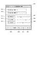
図23は、本実施例におけるクライアント101における文書編集アプリケーションにおいて、印刷処理を行った時に、CRT4006上に表示されるユーザインタフェースの例である。
【0322】
ここで説明する画面表示は、印刷処理の実行時ばかりでなく、印刷のための設定処理の実行時においても表示可能となる。
【0323】
図23において、2301は始めに表示されるダイアログパネルである。2301の菜かには出力先のプリントサーバを指定するための項目が選択できるようになっている。
【0324】
2302はプリントサーバを直接指定するためのトグルスイッチであり、2303はプリントサーバを本第一及び第二実施例で説明した優先度により指定する手段を用いることを示すトグルスイッチである。トグルスイッチ2302と2303は背反になっており、とちらか一方が必ず選択状態になるようになっていて、非選択状態であって一方を選択すると、選択状態にあった他方は非選択状態に切り替わるものとする。
【0325】
2304は「実行」ボタンであり、本ボタンが選択されると2302と2303の選択状態にあるものの処理が実行される。
【0326】
2305は、「中止」ボタンであり、本ボタンが選択されるとパネル2301を閉じて印刷のための処理或いは印刷設定のための処理を中止し、パネル2301表示前の処理状態に戻る。
【0327】
なお、トグルスイッチ2302、2303及びボタン2304、2305はキーボード又はポインティングデバイスなどの外部入力装置4008により選択する操作を行うことができる。
【0328】
図24は、プリントサーバを直接指定する場合に表示されるユーザインタフェース画面の例である。図23において、トグルスイッチ2302を選択して実行ボタン2304をユーザが選択した場合に、図24の処理が実行される。
【0329】
図24において、2401は出力先のプリントサーバを直接指定するためのダイアログパネルであり、出力先のプリントサーバを選択できるようになっている。
【0330】
2402は、出力先のプリントサーバを選択するためのリストボックスであり、選択可能なプリントサーバの名称がリスト上に列挙されていて、それぞれのプリントサーバが選択可能となっている。
【0331】
2403は、リストボックス2402の為のスクロールバーであり、選択可能なすべてのプリントサーバを表示しきれない場合のために、リストボックス2402と連動して利す都内の表示をスクロールさせることが可能となっている。
【0332】
2404は、「実行」ボタンであり、本ボタンを選択するとパネル2401及び2301を閉じて、リストボックス2402内で選択されているプリントサーバを、本クライアント101の文書編集アプリケーションにおける印刷依頼先として選択することができる。本処理が印刷実行時である場合には、引き続いて印刷のための指定されたプリントサーバへの出力処理が実行される。この出力処理とは、第一及び第二実施例で説明したように、印刷オーダーと印刷スクリプトを文書編集アプリケーションで作成し、プリントコントローラ103に送信する処理のことである。なお、リストボックス2402内に選択されているプリントサーバが存在しない場合(未選択の場合)には、「実行」ボタン4104は選択不可能な状態になっているものとする。
【0333】
2405は「戻る」ボタンであり、本ボタンを選択するとパネル2401を閉じて、図23におけるパネル2301を表示し、パネル2401を開く前の状態に戻ることができる。
【0334】
2406は「中止」ボタンであり、本ボタンを選択するとパネル2401及び2301を閉じて、印刷依頼のための処理、或いは印刷設定のための処理を完全に中止することができる。
【0335】
なお、リストボックス2402、スクロールバー2403及びボタン2404、2405、2406は、キーボード又はポインティングデバイスなどの外部入力装置4008により選択する操作を行うことができる。
【0336】
図24では、リストボックス2402内において、「プリントサーバ2」を示すアイテム2407が選択状態になっている。この状態で「実行」ボタン2404を選択すると、出力先にプリントサーバとして「プリントサーバ2」を指定することができる。
【0337】
図25は、プリントサーバを優先度により指定する場合に表示されるユーザインタフェース画面の例である。図23においてトグルスイッチ2303を選択して実行ボタン2304を選択した場合に、図25の処理が実行される。
【0338】
図25において、2501は出力先のプリントサーバを優先度により指定するためのダイアログパネルであり、優先度選択の手段を設定できるようになっている。
【0339】
2502はプリントサーバを単一のパラメータの優先順位により指定するためのトグルスイッチであり、2503はプリントサーバを書くパラメータの優先度の総合評価により指定する手段を用いることを示すためのトグルスイッチである。トグルスイッチ2502と2503は背反になっており、とちらか一方が必ず選択状態になるようになっていて、非選択状態であった一方を選択すると、選択状態にあった他方は非選択状態に切り替わるものとする。
【0340】
2504は、優先度を決めるためのパラメータとして「地理的な近さ」を指定するためのトグルスイッチであり、2505は同じく「出力時間」を、2506は「印刷品質」を指定するためのトグルスイッチである。トグルスイッチ2504と2505、2506は背反になっており、どれか一方が必ず選択状態になるようになっていて、非選択状態であって一方を選択すると、選択状態にあった他方は非選択状態に切り替わるものとする。なお、トグルスイッチ2504、2505、2506による設定は、「優先順位で選択する」旨のトグルスイッチ2502が選択状態にある場合にのに指定可能となっている。
【0341】
2507、2508、2509は、それぞれ「地理的な近さ」、「出力時間」、「印刷品質」の優先度の度数を指定するためのスライダーであり、つまみの位置を移動することによりそれぞれのパラメータの優先度を指定することができる。これらのスライダーにより設定した値が、図7で示した印刷オーダー内に記録される優先度の度数として405、407、409に格納されてプリントコントローラ103へ送信され、プリントコントローラ103内でのプリントサーバの判定に使用されることになる。なお、スライダー2507、2508、2509による設定は、「総合評価で選択する」旨のトグルスイッチ2503が選択状態にある場合にのみ指定可能となっている。
【0342】
2510は、「実行」ボタンであり、本ボタンが選択されるとパネル2501及び2301を閉じて、トグルスイッチ2502と2503の選択状態にあった方の処理が実行される。このとき、トグルスイッチ4202が選択されていた場合にはトグルスイッチ2504、2505、2506の選択状態が、トグルスイッチ2503が選択されていた場合には、スライダー2507、2508、2509の設定状態がそれぞれ処理に反映される。
【0343】
2511は、「戻る」ボタンでありl本ボタンが選択されるとパネル2501を閉じて図23におけるパネル2301を表示し、パネル2501表示前の処理状態に戻る。
【0344】
2512は、「中止」ボタンであり、本ボタンが選択されるとパネル2501及び2301を閉じて印刷依頼の為の処理、或いは印刷設定の為の処理を完全に中止することができる。
【0345】
2513は、「プリントサーバの詳細」ボタンであり、本ボタンが選択されると、後述するプリントサーバの詳細項目を設定するために必要な処理を行うことが可能となる。
【0346】
なお、トグルスイッチ2502、2503、2504、2505、2506、スライダー2507、2508、2509及びボタン2510、2511、2512、2513は、キーボード又はポインティングデバイスなどの外部入力装置4008により選択する操作を行うことができる。
【0347】
また、本図では優先度を決めるためのパラメータ例として「地理的な近さ」、「出力時間」、「印刷品質」を示したが、他のパラメータも同じ目的のために使用可能である。
【0348】
図26は、プリントサーバの詳細を設定する場合に表示されるユーザインタフェース画面の例である。図25において、ボタン2513を選択した場合に、図26の処理が実行される。
【0349】
図26において2601は出力可能なすべてのプリントサーバの詳細を設定するためのダイアログパネルであり、それぞれのプリントサーバのそれぞれのパラメータの優先度を設定できるようになっている。
【0350】
2602は、詳細を設定するためのプリントサーバを選択するためのリストボックスであり、選択可能なプリントサーバの名称がリスト上に列挙されていて、それぞれのプリントサーバが選択可能となっている。
【0351】
2603はリストボックス2602のためのスクロールバーであり、選択可能なすべてのプリントサーバを表示しきれない場合のために、リストボックス2602と連動してリスト内の表示をスクロールさせることが可能となっている。
【0352】
2604は、「変更」ボタンであり、本ボタンを選択することにより、リストボックス2602内で選択されているプリントサーバを優先度の詳細を設定する対象として選択することができる。リストボックス2602内に選択されているプリントサーバが存在しない場合(未選択の場合)には、「変更」ボタン2604は選択不可能な状態になっているものとする。
【0353】
2605は、「終了」ボタンであり、本ボタンを選択するとパネル2601を閉じて図25におけるパネル2501に戻り、パネル2601を開く前の状態から処理を続けることができる。
【0354】
図26ではリストボックス2602において、「プリントサーバ2」を示すアイテム2604が選択状態になっている。この状態で「変更」ボタン2604を選択すると、「プリントサーバ2」の優先度の詳細を変更することができる。
【0355】
2607、2608、2609はそれぞれ「地理的な近さ」、「出力時間」、「印刷品質」の優先度を指定するためのスライダーであり、つまみの位置を移動することによりそれぞれのパラメータの優先度に対する度数を指定することができる。これらのスライダーにより設定した値が、プリントコントローラ103内で管理されるプリントサーバ管理テーブル(図8)に記録される優先度の度数として登録され、プリントコントローラ内でのプリントサーバの判定に使用されることになる。
【0356】
2610は、「適用」ボタンであり、本ボタンが選択されると、クライアントコンピュータ101は、スライダー2607、2608、2609の設定をプリントコントローラ103へネットワークインタフェース4004を介して送信する。以後、それぞれの設定値がリストボックス2602で選択されたプリントサーバの各パラメータの優先度に対する度数として反映される。つまり、プリントコントローラ103で管理しているプリントサーバ管理テーブル(図8)が前述したような方法で更新され、プリントコントローラ103において、クライアント101から受信した印刷オーダーの印刷依頼先のプリントサーバを選択する際に使用される。
【0357】
2611は、「キャンセル」ボタンであり、本ボタンが選択されると、スライダー2607、2608、2609による操作は中断される。
【0358】
なお、「適用」ボタン2610或いは「キャンセル」ボタン2611の選択後には、スライダー2607、2608、2609の操作はできなくなり、リストボックス2602の操作に戻るようになる。
【0359】
また、スライダー2607、2608、2609による設定及びボタン2610、2611は、「変更」ボタン2604が選択された場合にのみ指定可能となっている。「変更」ボタン2604が選択された後は、「適用」ボタン2610又は「キャンセル」ボタン2611が選択されるまでの間は、リストボックス2602及び「変更」ボタン2604は操作できなくなる。
【0360】
また、いかなる場合においても、「終了」ボタン2605は選択可能となっている。
【0361】
なお、リストボックス2602、スクロールバー2603、スライダー2607、2608、2609及びボタン2604、2605、2610、2611は、キーボード又はポインティングデバイスなどの外部入力装置4008により選択する操作を行うことができる。
【0362】
また、本図では優先度を決めるためのパラメータ例として「地理的な近さ」、「出力時間」、「印刷品質」を示したが、他のパラメータも同目的のために使用可能である。
【0363】
なお、本実施例では、パネル2601はパネル2501のサブパネルとして説明したが、プリントコントローラ103上のプリントサーバを制御するための単体アプリケーションプログラムの機能として、プリントコントローラ103上で管理される各プリントサーバの優先度を管理する目的のために、パネル2601の機能を使用することもできる。
【0364】
<クライアントコンピュータでの処理>
図27は、本発明におけるクライアントコンピュータでの出力先選択処理を説明するためのフロー図である。
【0365】
この処理は、クライアントコンピュータ101における文書編集アプリケーションが、イメージサーバ102から受信した編集用の低解像度の画像データを編集し、図3で前述したような印刷スクリプトを生成して、印刷依頼を送信する処理のときに行われる。
【0366】
処理が始まると、S1において、まず図23に示したようなプリントサーバ指定画面をCRT4006に表示する。その画面上でユーザに対して、プリントサーバを直接指定するかプリントサーバを優先度で指定するかを選択させる。プリントサーバを直接指定すると選択された場合、つまりトグルスイッチ2302が選択された場合はS2に処理を移す。プリントサーバを優先度で指定すると選択された場合、つまりトグルスイッチ2303が選択された場合はS3に処理を移す。
【0367】
S2では、クライアント101はCRT4006に図24で説明した画面を表示する。この画面上でユーザに対して、印刷出力させるプリントサーバを選択させる。プリントサーバが選択されるとS6に処理を進める。
【0368】
S3では、クライアント101はCRT4006に図25で説明した画面を表示する。この画面上でユーザに対して、プリントコントローラ103内で「優先順位で選択する」のか「総合評価で選択する」のかを選択させる。優先順位で選択すると指定された場合は、S4に処理を進める。総合評価で選択すると指定された場合は、S5に処理を進める。
【0369】
S4では、図25で示しているように、「地理的な近さ」、「出力時間」、「印刷品質」のどのパラメータを優先に印刷出力先を決定するのかをユーザに選択させる。この選択処理は、トグルスイッチ2504〜2506のどれか選択されたかをCPU4001が判断することにより実現される。優先させるパラメータが選択されるとS6に処理を進める。
【0370】
S5では、図25で示されているように、「地理的な近さ」、「出力時間」、「印刷品質」のすべてのパラメータをスライダーバー2507〜2509を移動させることによりユーザに決定させる。すべてのパラメータが決定されるとS6に処理を進める。
【0371】
S6では、クライアントコンピュータ101は、図7で前述したような印刷オーダーを作成し、プリントコントローラ103へインターネットを介して送信する。
【0372】
図28は、本発明におけるクライアントコンピュータでの出力先選択処理を説明するためのフロー図である。
【0373】
図28の処理は、図25に示したユーザインタフェース画面例において、ボタン2513が選択された場合に、実行される。
【0374】
S1において、詳細設定のパラメータを変更したいプリントサーバをリストボックス2602の中からユーザに選択させる。
【0375】
S2では、図26の終了ボタン2605が押下されたかを判断する。終了ボタンがユーザにより選択されているとクライアント101が判断した場合は、処理を終了する。なお、このフローチャートではS2においてのみこの判断を行っているが、どのタイミングで終了の判断が行われてもよいことはいうまでもない。
【0376】
S3では、図26の変更ボタン2604が押下されたかを判断する。変更ボタンがユーザにより選択されているとクライアントが判断した場合は、リストボックス2602内で選択されているプリントサーバのパラメータをスライダーバー2607〜2609に表示して、S4に処理を進める。変更ボタンが選択されていない場合は、S1に処理を戻す。
【0377】
S4では、S1で選択されたプリントサーバの各パラメータをスライダーバー2607〜2609によりユーザに設定させる。パラメータ設定中にキャンセルボタン2611が押されたら(S5)、図26の「プリントサーバ詳細」のユーザインタフェース画面で選択されているプリントサーバの元のパラメータにスライダーバー2607〜2609を戻してCRT4006に表示し直して(S6)、S1に処理を戻す。
【0378】
S7では、プリントサーバの各パラメータを設定する処理中に適用ボタン2610が押されたかを判断する。ユーザが外部入力装置4008を介して適用ボタン2610を選択した場合は、S8に処理を進める。
【0379】
S8では、S1で選択されたプリントサーバに対して、S4で設定された各パラメータを設定するよう変更する。クライアントコンピュータ101で管理しているプリントサーバの詳細が変更されるとS9に処理を進める。
【0380】
S9では、S8で変更されたプリントサーバのパラメータ設定をプリントコントローラ103に登録するために、パラメータ設定情報をプリントコントローラ103へアップロードする。つまり、適用ボタン2610が押下されることにより、クライアントコンピュータ101は、インターネット介してプリントコントローラと接続して、パラメータ設定情報を送信するのである。プリントコントローラ103へのアップロードが終了すると、インターネット接続を切り、処理を終了する。
【0381】
また、図28で説明したプリントサーバの詳細の設定かつ、プリントコントローラへのアップロードは、クライアントコンピュータ101で行う必然性はない。つまり、図28の制御プログラムをプリントサーバが有していれば、各プリントサーバで自身のプリントサーバの詳細を設定し、プリントコントローラ103へアップロードすることも可能である。
【0382】
上記説明したように、本発明の情報処理装置の一実施例であるクライアントコンピュータ101の実施形態の特徴的構成について説明する。
【0383】
所望の画像の印刷を指示する情報処理装置(クライアント101)であって、画像データの出力を制御するためのプリントサーバ(104〜106)を直接指定する(図27のS2)か、プリントサーバを選択するための条件を指定する(図27のS3)かのどちらが選択されたかを判断する判断手段(図27のS1の制御プログラムによるCPU4001の機能)と、前記判断手段によりプリントサーバを直接指定するように選択された場合に、画像データの出力を制御するプリントサーバを選択させる選択手段(図27のS2の制御プログラムによるCPU4001の機能)と、前記判断手段によりプリントサーバを選択するための条件を指定するように選択された場合に、該条件を設定させる条件設定手段(図27のS3〜5の制御プログラムによるCPU4001の機能)と、前記選択手段により選択されたプリントサーバもしくは前記条件設定手段により設定された条件に基づいて、印刷オーダー(図7)を作成し、プリントコントローラに送信する印刷依頼手段(図27のS6の制御プログラムによるCPU4001の機能)とを有することを特徴とすることにより、ユーザの希望に合わせて印刷出力先を決定できる仕組みを提供できるものである。
【0384】
また、編集用の低解像度の画像データ(図3の301)をイメージサーバ(102)から受信する受信手段(ネットワークインタフェース4004)と、前記受信手段により受信した画像データを編集し、編集内容を示す編集情報(図3の306)を生成する編集手段(ROM4003に格納されている文書編集アプリケーションの機能)とを更に有し、前記印刷依頼手段は、前記編集手段により生成された編集情報(図3の306)と前記印刷オーダー(図7)とを一緒にプリントコントローラに送信することを特徴とすることにより、低解像度の画像データを受信するのでネットワーク上の負荷が減り、また印刷依頼時も編集情報を送信するので、実際に印刷したい高解像度の画像データを情報処理装置が送信する必要がなくなり、情報処理装置及びネットワークの負荷が減る仕組みを提供することができるものである。
【0385】
また、前記イメージサーバから受信する画像データは、前記イメージサーバ上に予め記憶されている小単位であるイメージタイル(図2)に分割されて伝送されることを特徴とすることにより、必要なタイルだけを送信すればよく、ネットワークの負荷が減る仕組みを提供することができるものである。
【0386】
また、前記編集情報は、前記編集で必要なイメージデータを識別するID情報(図3の306参照)を有していることを特徴とすることにより、編集情報を送信するだけで、実際の印刷で必要な高解像度の画像データが外部装置で認識できる仕組みを提供できるものである。
【0387】
また、前記編集情報は、スクリプト形式(図3の306参照)で記述されていることを特徴とすることにより、編集情報を解析する装置側で、データが扱いやすくなる仕組みを提供できるものである。
【0388】
また、前記条件は、前記情報処理装置からの地理的な距離(2504)或いは出力が実施されるプリントサーバの負荷状況により出力を完了するために要する時間(2505)或いは出力画像に要求される解像度等の画像品質(2506)の少なくとも1つを含んでいることを特徴とすることにより、ユーザが希望する優先度を詳細に決定できる仕組みを提供するものである。
【0389】
また、前記プリントサーバの前記条件に対応するパラメータを設定するプリントサーバ設定手段(図28のS1、S4、S8の制御プログラムによるCPU4001の機能)と、前記プリントサーバ設定手段により設定された前記プリントサーバのパラメータを、前記プリントコントローラ(103)に格納されているプリントサーバ管理テーブル(図8)に登録する登録手段(図28のS9の制御プログラムによるCPU4001の機能)とを更に有していることを特徴とすることにより、プリントサーバの詳細を自身で設定できる仕組みを提供するものである。
【0390】
また、前記プリントコントローラは、前記登録手段により前記プリントサーバ管理テーブルに登録されたパラメータに基づいて、前記印刷オーダーの印刷出力先のプリントサーバを決定することを特徴とすることにより、ユーザがもっとも望んだ出力先のプリントサーバに印刷依頼をすることができる仕組みを提供するものである。
【0391】
また、前記編集とは、モザイク処理、ぼかし処理、色変換、階調変換処理或いは、テンプレート、スタンプ、イラストなどのデータを追加する処理であることを特徴とすることにより、画像に対するさまざまな編集処理を行うことを可能にし、更にこのような編集処理は直接画像を改変しないため、本情報処理装置内での編集処理は実際に印刷する高解像度の画像データを必要としなくなり情報処理装置及びネットワークの負荷が減る仕組みを提供するものである。
【0392】
また、前記プリントコントローラ或いは前記イメージサーバとは、インターネットを介して接続されていることを特徴とすることにより、インターネットにおける印刷依頼の仕組みを提供するものである。
【0393】
【発明の効果】
以上説明したように、本発明によれば、イメージを含んだ画像情報を出力する際に、複数のプリントサーバおよび、それらをを統括するプリントコントローラをシステム内に用意することによって、また、画像内のイメージ情報を別の経路で伝送する手段を用いることによって、システム内に存在する出力装置の中で、経済性、時間、地理的要因など要求される条件に最も適した出力装置を、選択することを可能としている。
【0394】
また、クライアントは、低解像度の画像データを受信するのでネットワーク上の負荷が減り、また印刷依頼時も編集情報を送信するので、実際に印刷したい高解像度の画像データを情報処理装置が送信する必要がなくなり、情報処理装置及びネットワークの負荷が減ることを可能としている。
【0395】
また、プリントサーバの詳細を自身で設定することを可能としている。
【0396】
また、クライアントにおいて画像に対するさまざまな編集処理を行うことを可能にし、更にこのような編集処理は直接画像を改変しないため、クライアント内での編集処理は実際に印刷する高解像度の画像データを必要としなくなり、クライアント及びネットワークの負荷が減る仕組みを提供するものである。
【図面の簡単な説明】
【図1】本発明のシステム構成図である。
【図2】本発明で使用するイメージフォーマットの説明図である。
【図3】本発明で使用するページ記述言語で記述されたスクリプトの例の説明図である。
【図4】本発明で使用されるプリントコントローラのシステム構成を示すブロック図である。
【図5】本発明で使用されるプリントサーバのシステム構成を示すブロック図である。
【図6】本発明におけるプリントコントローラの処理を示すフロー図である。
【図7】本発明におけるプリントコントローラへ伝達される印刷オーダーのフォーマットを示す摸式図である。
【図8】本発明におけるプリントコントローラ内で管理されるプリントサーバ管理テーブルのフォーマットを示す摸式図である。
【図9】プリントサーバ管理テーブルが変更される状況を示すための摸式図である。
【図10】プリントサーバ管理テーブルが変更される処理の流れを示すフロー図である。
【図11】プリントサーバ管理テーブルが変更される状況を示すための摸式図である。
【図12】総合評価を導入したプリントサーバ管理テーブルの別の例を説明する摸式図である。
【図13】プリントコントローラの外部記憶媒体内でのメモリマップである。
【図14】プリントサーバの外部記憶媒体内でのメモリマップである。
【図15】本発明の他の実施例のシステム構成図である。
【図16】クライアント(図1の101)からの要求に対するイメージサーバ102の処理を示すフロー図である。
【図17】プリントサーバ104−106からの要求に対するイメージサーバ102の処理を示すフロー図である。
【図18】イメージサーバ102のプログラムの外部記憶媒体(フロッピーディスクなどのリムーバルディスク)内でのメモリマップの一例を示す図。
【図19】本実施例に適用可能なプリンタの構造を示す図。
【図20】本実施例に適用可能なプリンタの構造を示す図。
【図21】本発明で使用されるイメージサーバのシステム構成を示すブロック図である。
【図22】本発明で使用されるクライアントコンピュータのシステム構成を示すブロック図である。
【図23】クライアントにおける印刷指示の際に表示されるユーザインタフェース画面の一例である。
【図24】クライアントにおける印刷出力先のプリントサーバを選択するユーザインタフェース画面の一例である。
【図25】クライアントにおける印刷出力先のプリントサーバを選択する際の条件を設定するユーザインタフェース画面の一例である。
【図26】クライアントにおけるプリントサーバの詳細を設定するユーザインタフェース画面の一例である。
【図27】印刷依頼する際のクライアントの処理を示すフロー図である。
【図28】プリントサーバのパラメータを設定する処理を示すフロー図である。
【符号の説明】
101 文書編集アプリケーションを有するクライアントコンピュータ
102 イメージサーバ
103 プリントコントローラ
104、105、106 プリントサーバ
201 イメージファイル
202 解像度0のイメージ
203 解像度1のイメージ
204 解像度nのイメージ
205 解像度0のイメージに対するイメージタイルの関係
301 イメージ203とイメージタイルの関係
302 クライアントコンピュータ101の文書編集アプリケーションで作成される文書
303 文書302に含まれるイメージデータ
304 文書302に含まれる図形データ
305 文書302に含まれる文字列データ
306 文書302を変換したスクリプトの例
1001 CPU
1002 RAM
1003 ROM
1004 ネットワークインターフェイス
2001 CPU
2002 RAM
2003 ROM
2004 ネットワークインターフェイス
401 個人識別情報長
402 個人識別情報
403 出力指定パラメータ数
404、406、408、410 出力指定パラメータ1、2、3、N、
405、407、409、411 パラメータ1、2、3、Nの優先度度数
701 変更前のプリントサーバ管理テーブルの状態
702 変更後のプリントサーバ管理テーブルの状態
703、704 プリントサーバ1、2の状態を示す行
705 パラメータ2の状態を示す列
706、707 プリントサーバ1、2のパラメータ2に対する優先度数
801、802、803、804 プリントサーバ1、2、3、Mの状態を示す行
805、806、807 パラメータ1、2、Nの状態を示す列
808 プリントサーバMのパラメータNに対する優先度数
809 各プリントサーバの総合評価を示す列
810 プリントサーバ1の総合評価
997 プリントサーバ管理テーブルの記憶領域[0001]
BACKGROUND OF THE INVENTION
The present invention relates to a print control system, a print controller, an image server, an information processing apparatus, and a control method thereof that can output image information in an optimum apparatus using a plurality of output devices.
[0002]
[Prior art]
In the prior art, by using a network such as the Internet or an intranet, image data can be transmitted from a remote operation terminal to a specific print server and requested to be output.
[0003]
In the case where a plurality of print servers are provided on the system, output processing can be executed in the requested printer by designating a print server that executes output when requesting image output from the operation terminal. It was.
[0004]
[Problems to be solved by the invention]
In the prior art, when requesting image output to a remote area, it is necessary to occupy a transmission path (network) in order to transmit all the image data to be output. There is a problem that it takes time to complete the output, and the cost required for image data transmission (line usage fee, etc.) increases.
[0005]
In addition, it has been possible to reduce the load on the transmission path and the amount of transmission information by classifying image output information into image information and non-image information and transmitting them separately. Since information is transmitted through the transmission path, there has been no significant reduction in the amount of transmitted information and costs.
[0006]
Furthermore, in the prior art, regardless of the usage status of the output device that requests image output, the output of the target output device is executed, so that resources in the entire system cannot be effectively used.
[0007]
[Means for Solving the Problems]
According to the present invention, in order to significantly reduce the amount and cost of transmission information associated with image transmission for image output, image information is stored in the image server in advance among image output information including images. Made it possible to use.
[0008]
In addition, the print server that performs image output is automatically determined by the print controller according to the load status of the entire system and the quality and functions required for the output image, so that resources in the system can be used effectively. It was possible.
[0009]
Furthermore, by using a means for designating the criteria for selecting the print server that performs image output in the request information of the system user, the output device can be selected flexibly according to the specific request of the user. Made it possible to do.
[0010]
The present invention has been made in view of the above problems, and the print control system of the present invention has the following configuration.
[0011]
That is, in a print control system for printing image data, a plurality of print servers for controlling high-definition output of image data using image data stored in the image server, and prior to printing, the image And a print controller for selecting a print server to which image data from the server is to be transmitted based on information different from information for instructing selection of each print server.
[0012]
The print control system of the present invention has the following configuration.
[0013]
That is, in a print control system for printing image data, a plurality of print servers for controlling output of image data using image data stored in an image server for storing image data; Receiving means for receiving a print order for the image data, detecting means for detecting whether the received print order includes instruction information relating to selection of the print server, and detecting that the instruction information is not included A print controller that checks whether the execution condition of the print server is satisfied, and designates one of the plurality of print servers to execute the print processing of the image data; The execution condition including these parameters is different from the instruction information.
[0032]
DETAILED DESCRIPTION OF THE INVENTION
[First Example]
<System configuration>
FIG. 1 is a system configuration diagram in which printing control according to the present invention is performed.
[0033]
In FIG. 1,
[0034]
An
[0035]
[0036]
[0037]
The
[0038]
<Image format>
FIG. 2 is an explanatory diagram for explaining an image format of FlashPix (registered trademark) which is one embodiment of image data used in the present invention. The
[0039]
In FIG. 2, 201 denotes an image file in the flash pix format. The
[0040]
Each resolution image is divided and managed into square image tiles having a fixed number of pixels.
[0041]
Since the number of pixels of the image tile is fixed, the number and ID of image tiles indicating the same portion are different between images having different resolutions. For example, the area of the image tile representing the same part at the
[0042]
As described above, since the image server of the present invention has image data of multiple resolutions, a low-resolution image can be used for processing that requires a low-resolution image, such as editing. There are effects such as improved operability by speeding up the transmission process.
[0043]
<Script>
FIG. 3 is an explanatory diagram of an example of a script described in the page description language used in the present invention.
[0044]
In FIG. 3,
[0045]
[0046]
[0047]
A
[0048]
The
[0049]
The
[0050]
In the
[0051]
In this way, a history of editing commands edited by the document editing application of the
[0052]
As described above, the
[0053]
<Block diagram of print controller>
FIG. 4 is a block diagram showing the system configuration of the print controller.
[0054]
In FIG. 4,
[0055]
[0056]
[0057]
[0058]
[0059]
[0060]
[0061]
[0062]
[0063]
<Block diagram of print server>
FIG. 5 is a block diagram illustrating a system configuration of the
[0064]
In FIG. 5,
[0065]
[0066]
[0067]
[0068]
[0069]
[0070]
[0071]
[0072]
[0073]
A
[0074]
[0075]
<Description of operation>
First, the overall operation of this system will be described with reference to FIG.
[0076]
The user uses the document creation application function of the
[0077]
When the user performs an operation for requesting a print service, the document editing application of the
[0078]
In the
[0079]
The
[0080]
<Processing in the print controller>
FIG. 6 is a flowchart for explaining the flow of processing in the print controller according to the present invention.
[0081]
In the figure, a series of processing is started by transmitting a print order and a print script from the document editing application of the
[0082]
The print order includes information (output designation information) for selecting a print server to be output in the format described later in FIG. 7, and the output designation information is analyzed from the print order in S2.
[0083]
The print server management table is updated as necessary in S3 based on the result of the analyzed output designation information.
[0084]
The print server management table is a table used to manage the state of the print servers (104, 105, 106) connected in the system and determine a print server that executes output according to the print order. (Details will be described later in FIG. 8).
[0085]
In S4, after confirming the operating state of the print server located at the head of the table and determining in S5 whether or not the print server is usable, in S6, if it is usable, The print order and print script are transmitted to the print server to instruct image output.
[0086]
If it is determined in S5 that the corresponding print server does not satisfy the execution condition, the print server management table is corrected and updated in S7.
[0087]
As a result of the print server management table update, it is determined in S8 whether there is a print server that can be newly executed. If there is a print server, the status of the print server is confirmed in S9, and the process returns to S5.
[0088]
If the next print server is not found in S8, an emergency processing means such as notifying the client of an error in S10 is performed, and then the series of processes is terminated.
[0089]
<Processing on the print server>
The
[0090]
If the transmitted print script contains information about the image, the necessary image tiles are directly acquired from the
[0091]
At this time, the used image data and image tiles are stored in the
[0092]
<Print order>
FIG. 7 is a schematic diagram showing the format of the print order transmitted from the
[0093]
A series of
[0094]
In the figure, 401 is a parameter indicating the personal identification information length, and indicates the data length (data size) of the
[0095]
The
[0096]
[0097]
[0098]
[0099]
410 indicates that N parameters are prepared. Therefore, the number of output designation parameters of 403 is N.
[0100]
405, 407, 409, and 411 are numerical values (priorities) for indicating the priority numbers of
[0101]
However, if the priorities are equal, the order is determined according to the priority order determination procedure in the print controller, and therefore the priority order cannot be determined only by this information.
[0102]
Note that the print order transmitted from the
[0103]
<Print server management table>
FIG. 8 is a schematic diagram showing the format of a print server management table managed in the
[0104]
In this table, the frequency of each parameter regarding all print servers connected in the system is recorded. The superiority or inferiority of the print server is determined by the magnitude of this frequency.
[0105]
In the figure,
[0106]
Each column in the table means each parameter. In the figure, as an example, 502, 503, and 504 mean “
[0107]
The number of print servers (M in the figure) similar to that of 501 is prepared. 505 is a line of “
[0108]
Numerical values corresponding to each print server and parameters are recorded in the table. For example, P (1, 1) of 508 is a value indicating the value of “
[0109]
It is assumed that the order of the print server rows in this table matches the order of superiority or inferiority of the print server that executes image output. (That is, the order of 1, 2, 3,... N in FIG. 8 is the priority order.) Therefore, when the frequency for each print server parameter is changed, the order of the rows in the table is corrected as needed. The
[0110]
Further, the superiority or inferiority of each print server is changed and determined in accordance with the priority number of the parameter passed in the output designation information (FIG. 7) in the print order transmitted from the
[0111]
The print server management table is stored in the
[0112]
<Example 1 of changing print server management table>
FIG. 9 is a schematic diagram for illustrating a situation in which the print server management table shown in FIG. 8 is updated.
[0113]
In the figure,
[0114]
[0115]
Assuming that the frequencies for the
[0116]
For example,
P (3,1)> P (1,1)> P (2,1) (Formula 1)
If there is such a magnitude relationship, the table is changed according to the priority, and is corrected in the order of 605, 603, and 604 such as 602.
[0117]
In this way, the print server management table is changed as needed according to the change in the frequency of the parameters of each print server.
[0118]
FIG. 10 is a flowchart for illustrating the flow of processing for changing the print server management table described above.
[0119]
In FIG. 10, the table needs to be changed for some reason in S1. For example, the process in S3 or S7 of FIG.
[0120]
In S2, the priority of each print server with respect to the highest parameter is compared based on the information in the management table.
[0121]
If the comparison result management table needs to be updated in S3, the table is updated.
[0122]
Normally, this should end the update of the table. However, in the case where there are print servers of the same order, the following processing is continued.
[0123]
In S4, it is checked whether there is a print server having the same rank. If there is no same rank, the process is terminated.
[0124]
If there is a server with the same rank, it is checked in S5 whether there are any parameters that are not yet used for comparison.
[0125]
If an unused parameter remains, the server priority is compared based on the parameter in S6, and the process returns to S3.
[0126]
If there are no unused parameters left in S5, there is no way to compare any more, so the servers of the same rank end the table update in the order before the update.
[0127]
<Example 2 of changing print server management table>
FIG. 11 shows the print server management table updated when the priority order of the parameters is changed in the output designation information in the print order shown in FIG. 7 and when a different priority order is requested in the output designation information. It is a model for showing a condition.
[0128]
In the figure,
[0129]
[0130]
Here, it is assumed that
[0131]
Now, assuming that the frequencies for the
[0132]
For example,
P (2,2)> P (1,2) (Formula 2)
If there is such a magnitude relationship, the table is changed according to the priority, and is corrected in the order of 702.
[0133]
In this way, the print server management table is changed as needed according to the change in the frequency of the parameters of each print server.
[0134]
Since the flow of the above processing is not substantially different from the flow diagram of FIG. 10, a description of a new diagram will not be given here.
[0135]
In FIG. 10, after a table change factor occurs in S1, the print server management table is updated according to the priority order indicated in the print order.
[0136]
Thereafter, the processes after S2 in FIG. 10 are executed.
[0137]
<Introducing integrated points in the priority determination method>
The print server priority determination method described with reference to FIGS. 9 and 11 treats each parameter independently and uses a parameter having a high priority as an absolute condition. However, in general implementation, it is possible to determine the rank by comprehensive evaluation of a plurality of parameters without using a single parameter as a determining factor.
[0138]
FIG. 12 is a schematic diagram of a print server management table when comprehensive evaluation is used.
[0139]
In the figure, each of the
[0140]
Each column of 805, 806, and 807 records the priority of each print server for
[0141]
Here, P (M, N) of 808 is a priority for the parameter N of the print server M.
[0142]
A
[0143]
Here, the print servers in each column are arranged from the top in the order of overall evaluation score. Therefore, when a print order is received, output is tried sequentially from a print server having a high overall evaluation according to this table.
[0144]
As a method for calculating the comprehensive evaluation score, for example, the following can be considered.
[0145]
A coefficient is set for each parameter according to the priority level, and a sum obtained by multiplying the priority for each parameter of each print server by the coefficient is used as an overall evaluation score.
[0146]
That is, if the coefficient of the parameter N is A (N), it can be expressed as
Q (M) = A (1) * P (M, 1) + A (1) * P (M, 1) +… + A (N) * P (M, N) (Formula 3)
[0147]
Here, although the coefficient A (M, N) is treated as constant, it can be treated as variable according to the system state and the print order.
[0148]
<Loading programs from media>
FIG. 13 is an example of a memory map in an external storage medium (a removable disk such as a floppy disk) for the print controller program.
[0149]
In FIG. 13,
[0150]
An
[0151]
The print controller program is installed in the
[0152]
At this time, the print server management table is loaded into the
[0153]
FIG. 14 is an example of a memory map in the external storage medium (removable disk such as a floppy disk) of the print server program.
[0154]
In FIG. 14,
[0155]
The print server program is installed in the
[0156]
[Second Example]
In the above embodiment, the system in which the
[0157]
<System configuration>
FIG. 15 is a system configuration diagram showing another embodiment of the print control apparatus of the present invention.
[0158]
In FIG. 15,
[0159]
[0160]
Further, 103 also has a function as an image server. That is, an image of an image format in which one screen is divided and managed by a plurality of tiles can be held at a plurality of resolutions, and image tile data of a specified resolution image in an image file can be provided via a network.
[0161]
[0162]
A
[0163]
<Device configuration>
4 is a block diagram of the
[0164]
<Description of operation>
The overall operation of this system will be described with reference to FIG.
[0165]
The user creates the
[0166]
When the user performs an operation for requesting a print service, the document editing application of the
[0167]
In the
[0168]
The
[0169]
<Processing in the print controller>
FIG. 6 is a flowchart for explaining the flow of processing in the
[0170]
In the figure, a series of processing is started by transmitting a print order and a print script from the
[0171]
The print order includes information (output designation information) for selecting a print server to be output in the format described later in FIG. 7, and the output designation information is analyzed from the print order in S2.
[0172]
The print server management table is updated as necessary in S3 based on the result of the analyzed output designation information.
[0173]
The print server management table is a table used to manage the state of the print servers (104, 105, 106) connected in the system and determine a print server that executes output according to the print order. (Details will be described later.)
[0174]
In S4, after confirming the operating state of the print server located at the head of the table and determining in S5 whether or not the print server is usable, in S6, if it is usable, The print order and print script are transmitted to the print server to instruct image output.
[0175]
If it is determined in S5 that the corresponding print server does not satisfy the execution condition, the print server management table is corrected and updated in S7.
[0176]
As a result of the print server management table update, it is determined in S8 whether there is a print server that can be newly executed. If there is a print server, the status of the print server is confirmed in S9, and the process returns to S5.
[0177]
If the next print server is not found in S8, an emergency processing means such as notifying the client of an error in S10 is performed, and then the series of processes is terminated.
[0178]
<Processing on the print server>
The
[0179]
If the transmitted print script contains information about the image, the necessary image data and image tiles are directly acquired from the
[0180]
At this time, the used image data and image tiles are stored in the
[0181]
<Print order>
FIG. 7 is a schematic diagram showing the format of the print order transmitted from the
[0182]
A series of
[0183]
In the figure, 401 is a parameter indicating the personal identification information length, and indicates the data length of the subsequent
[0184]
The
[0185]
[0186]
[0187]
[0188]
410 indicates that N parameters are prepared. Therefore, the number of output designation parameters of 403 is N.
[0189]
405, 407, 409, and 411 are numerical values (priorities) for indicating the priority numbers of
[0190]
However, if the priorities are equal, the order is determined according to the priority order determination procedure in the print controller, and therefore the priority order cannot be determined only by this information.
[0191]
Note that the print order transmitted from the
[0192]
<Print server management table>
FIG. 8 is a schematic diagram showing the format of the print server management table managed in the print controller.
[0193]
In this table, the frequency of each parameter regarding all print servers connected in the system is recorded. The superiority or inferiority of the print server is determined by the magnitude of this frequency.
[0194]
In the figure,
[0195]
Each column in the table means each parameter. In the figure, as an example, 502, 503, and 504 mean “
[0196]
The number of print servers (M in the figure) similar to that of 501 is prepared. 505 is a line of “
[0197]
Numerical values corresponding to each print server and parameters are recorded in the table. For example, P (1, 1) of 508 is a value indicating the value of “
[0198]
It is assumed that the order of the print server rows in this table matches the order of superiority or inferiority of the print server that executes image output. (That is, the order of 1, 2, 3,... N in FIG. 8 is the priority order.) Therefore, when the frequency for each print server parameter is changed, the order of the rows in the table is corrected as needed. The
[0199]
Further, the superiority or inferiority of each print server is changed and determined in accordance with the priority number of parameters passed in the output designation information (FIG. 7) in the print order transmitted from the document editing application. Even in this case, the order of the rows in the table is corrected again.
[0200]
The print server management table is stored in the
[0201]
<Example 1 of changing print server management table>
FIG. 9 is a schematic diagram for illustrating a situation in which the print server management table shown in FIG. 8 is updated.
[0202]
In the figure,
[0203]
[0204]
Assuming that the frequencies for the
[0205]
For example,
P (3,1)> P (1,1)> P (2,1) (Formula 1)
If there is such a magnitude relationship, the table is changed according to the priority, and is corrected in the order of 605, 603, and 604 such as 602.
[0206]
In this way, the print server management table is changed as needed according to the change in the frequency of the parameters of each print server.
[0207]
FIG. 10 is a flowchart for illustrating the flow of processing for changing the print server management table described above.
[0208]
In FIG. 10, the table needs to be changed for some reason in S1. For example, the process in S3 or S7 of FIG.
[0209]
In S2, the priority of each print server with respect to the highest parameter is compared based on the information in the management table.
[0210]
If the comparison result management table needs to be updated in S3, the table is updated.
[0211]
Normally, this should end the update of the table. However, in the case where there are print servers of the same order, the following processing is continued.
[0212]
In S4, it is checked whether there is a print server having the same rank. If there is no same rank, the process is terminated.
[0213]
If there is a server with the same rank, it is checked in S5 whether there are any parameters that are not yet used for comparison.
[0214]
If an unused parameter remains, the server priority is compared based on the parameter in S6, and the process returns to S3.
[0215]
If there are no unused parameters left in S5, there is no way to compare any more, so the servers of the same rank end the table update in the order before the update.
[0216]
<Example 2 of changing print server management table>
FIG. 11 shows the print server management table updated when the priority order of the parameters is changed in the output designation information in the print order shown in FIG. 7 and when a different priority order is requested in the output designation information. It is a model for showing a condition.
[0217]
In the figure,
[0218]
[0219]
Here, it is assumed that
[0220]
Now, assuming that the frequencies for the
[0221]
For example,
P (2,2)> P (1,2) (Formula 2)
If there is such a magnitude relationship, the table is changed according to the priority, and is corrected in the order of 702.
[0222]
In this way, the print server management table is changed as needed according to the change in the frequency of the parameters of each print server.
[0223]
Since the flow of the above processing is not substantially different from the flow diagram of FIG. 10, a description of a new diagram will not be given here.
[0224]
In FIG. 10, after a table change factor occurs in S1, the print server management table is updated according to the priority order indicated in the print order.
[0225]
Thereafter, the processes after S2 in FIG. 10 are executed.
[0226]
<Introducing integrated points in the priority determination method>
The print server priority determination method described with reference to FIGS. 9 and 11 treats each parameter independently and uses a parameter having a high priority as an absolute condition. However, in general implementation, it is possible to determine the rank by comprehensive evaluation of a plurality of parameters without using a single parameter as a determining factor.
[0227]
FIG. 12 is a schematic diagram of a print server management table when comprehensive evaluation is used.
[0228]
In the figure, each of the
[0229]
Each column of 805, 806, and 807 records the priority of each print server for
[0230]
Here, P (M, N) of 808 is a priority for the parameter N of the print server M.
[0231]
A
[0232]
Here, the print servers in each column are arranged from the top in the order of overall evaluation score. Therefore, when a print order is received, output is tried sequentially from a print server having a high overall evaluation according to this table.
[0233]
As a method for calculating the comprehensive evaluation score, for example, the following can be considered.
[0234]
A coefficient is set for each parameter according to the priority level, and a sum obtained by multiplying the priority for each parameter of each print server by the coefficient is used as an overall evaluation score.
[0235]
That is, if the coefficient of the parameter N is A (N), it can be expressed as
Q (M) = A (1) * P (M, 1) + A (1) * P (M, 1) +… + A (N) * P (M, N) (Formula 3)
[0236]
Here, although the coefficient A (M, N) is treated as constant, it can be treated as variable according to the system state and the print order.
[0237]
<Loading programs from media>
FIG. 13 is an example of a memory map in an external storage medium (a removable disk such as a floppy disk) for the print controller program.
[0238]
In FIG. 13,
[0239]
An
[0240]
The print controller program is installed in the
[0241]
At this time, the print server management table is loaded into the
[0242]
FIG. 14 is an example of a memory map in the external storage medium (removable disk such as a floppy disk) of the print server program.
[0243]
In FIG. 14,
[0244]
The print server program is installed in the
[0245]
<Block diagram of image server>
FIG. 21 is a block diagram showing the system configuration of the image server.
[0246]
In FIG. 21,
[0247]
[0248]
[0249]
[0250]
[0251]
[0252]
[0253]
[0254]
[0255]
<Image server processing flow>
FIGS. 16 and 17 are flowcharts for showing the processing flow of the image server (102 in FIG. 1) in the present invention.
[0256]
FIG. 16 is a flowchart showing processing of the
[0257]
In FIG. 16, when the processing of the
[0258]
If the received content is image data transmission to the
[0259]
If the image data requested in S5 does not exist, an error is notified to the
[0260]
At this time, the
[0261]
If the image file exists, a transmission buffer is secured on the
[0262]
In step S7, one image tile having a low resolution to be used for editing processing in the
[0263]
Since the image file is managed for each resolution as described with reference to FIG. 2, it is easy to obtain an image tile having a necessary resolution from the file.
[0264]
In S7, an identifier represented by a so-called Internet address for uniquely representing the image file is simultaneously written in the transmission buffer.
[0265]
This address is used as a means for identifying the image file in the
[0266]
Note that the image tile ID in the information used in the script is the tile that is used for the first time through the editing process in the
[0267]
When the writing of information to the transmission buffer is completed, the data is transmitted to the client in S8, and the process returns to S2 to wait for the next reception.
[0268]
FIG. 17 is a flowchart showing processing of the
[0269]
In FIG. 17, when the processing of the
[0270]
When any data is received in S2, the analysis from S3 is performed.
[0271]
If the received content is image data transmission to the print server 104-106 in S3, the processing from S4 is performed, and if it is any other content, the other processing is performed and the processing returns to S2, but the processing content is mentioned here. do not do. If the transmitted content is a request from the
[0272]
If the image data requested in S5 does not exist, an error is notified to the
[0273]
If the image file exists, a transmission buffer is secured on the
[0274]
In step S7, all the image tiles having the requested resolution and ID are read from the corresponding image data file, and written in the transmission buffer prepared in step S6.
[0275]
Since the image file is managed by tile ID for each resolution as described with reference to FIG. 2, it is easy to acquire an image tile having a required ID at a required resolution from the same file.
[0276]
When the writing of information to the transmission buffer is completed, the data is transmitted to the
[0277]
<Loading program from media>
FIG. 18 is an example of a memory map in an external storage medium (a removable disk such as a floppy disk) for the program of the
[0278]
In FIG. 18,
[0279]
The program of the
[0280]
Next, the structure of the print portion of the image reproduction system applicable to this embodiment will be described.
[0281]
The configurations of the laser beam printer and the ink jet printer to which this embodiment is applied will be described with reference to FIGS. The printer to which the present embodiment is applied is not limited to the laser beam printer and the ink jet printer, and it is obvious that other printers may be used.
[0282]
FIG. 19 is a cross-sectional view showing a configuration of a first recording apparatus to which the present invention can be applied. For example, the case of a laser beam printer (LBP) is shown.
[0283]
In the figure,
[0284]
FIG. 20 is an external view showing the configuration of a second recording apparatus to which the present invention can be applied. For example, an inkjet recording apparatus (IJRA) is shown.
[0285]
In the drawing, the carriage HC that engages with the spiral groove 5004 of the lead screw 5005 that rotates via the driving force transmission gears 5011 and 5009 in conjunction with forward and reverse rotation of the
[0286]
[0287]
These capping, cleaning, and suction recovery are configured so that desired processing can be performed at their corresponding positions by the action of the lead screw 5005 when the carriage comes to the home position side region. It is only necessary to be configured to perform the above.
[0288]
As described above, the image output control program can be supplied from the information recording medium to the image reproducing system, or directly accessed and executed by the information recording medium. The image playback system can easily control the output of an information recording medium recorded in a plurality of different recording formats with an image output control program corresponding to each recording format. The image output control required by the invention can be performed.
[0289]
In addition, since the image format and the corresponding output control program are provided by the same information recording medium, the system automatically corresponds to the image format of the information recording medium. Since it can be set, there is no need to set an operation program in accordance with the information recording medium, so that the present invention can be easily executed.
[0290]
As is apparent from the above description, according to the present invention, in order to greatly reduce the amount and cost of transmission information associated with image transmission for image output, image information is preliminarily stored in the image output information including the image. It is possible to use what is stored in the server.
[0291]
In addition, the print server that performs image output is automatically determined by the print controller according to the load status of the entire system and the quality and functions required for the output image, so that resources in the system can be used effectively. It was possible.
[0292]
Furthermore, by using a means for designating the criteria for selecting the print server that performs image output in the request information of the system user, the output device can be selected flexibly according to the specific request of the user. Made it possible to do.
[0293]
As is apparent from the above description, the present invention can provide the following system, print controller, image server, print server, print control method, apparatus, or recording medium. That is, according to the present invention, in a print control system for printing image data, an image server for storing image data, and image data stored in the image server by using the image data. Selection of a plurality of print servers for controlling fine output, a client for instructing printing of a desired image, and a print server to which image data from the image server is to be transmitted prior to printing based on an instruction from the client A print controller that performs printing based on information different from information for instructing selection of each print server.
[0294]
In addition, in a print control system for printing image data, an image server for storing image data, and for controlling high-definition output of image data using image data stored in the image server. A plurality of print servers, and a print controller that selects a print server to which image data from the image server is to be transmitted based on information different from information instructing selection of each print server prior to printing. A print control system characterized by the above.
[0295]
Also, in a print control system for printing image data, a plurality of print servers for controlling high-definition output of image data using image data stored in the image server for storing image data And a print controller that selects a print server to which image data from the image server is to be transmitted based on information different from information for instructing selection of each print server prior to printing. It is a printing control system.
[0296]
Also, in a print control system for printing image data, an image server for storing image data, and a print for controlling printing to which image data from the image server should be transmitted prior to printing A print control system comprising: a print controller that performs selection of a server based on information different from information for instructing selection of each print server.
[0297]
A selection unit that selects a plurality of print servers for controlling output of the image data using the image data stored in the image server for storing the image data; and the selection unit selects Selection control means for controlling the selection so as to select a print server to which image data from the image server should be transmitted based on information different from information instructing selection of each print server. The print controller.
[0298]
An image server for storing image data, wherein the image data is stored using the image data stored in the image server prior to printing based on an instruction from a client that instructs printing of a desired image. Transmission control means for transmitting the desired image to a print server determined based on information different from the information instructing selection of the print server among a plurality of print servers for controlling high-definition output of An image server characterized by the above.
[0299]
A selection function for selecting a plurality of print servers for controlling output of the image data using the image data stored in the image server for storing the image data; A selection control function for controlling the selection so that selection of a print server to which image data from the image server is to be transmitted is based on information different from information for instructing selection of each print server. This is a printing control method.
[0300]
In addition, a function for receiving an instruction from a client instructing printing of a desired image, and a plurality of functions for controlling high-definition output of image data using accumulated image data prior to print control based on the instruction. A print control method comprising: a transmission control function for transmitting the desired image to a print server determined based on information different from information instructing selection of the print server among the print servers. .
[0301]
A selection function for selecting a plurality of print servers for controlling output of the image data using the image data stored in the image server for storing the image data; A selection control function for controlling the selection so that selection of a print server to which image data from the image server is to be transmitted is based on information different from information for instructing selection of each print server. Recording medium.
[0302]
In addition, a function for receiving an instruction from a client instructing printing of a desired image, and a plurality of functions for controlling high-definition output of image data using accumulated image data prior to print control based on the instruction. A recording medium having a transmission control function for transmitting the desired image to a print server determined based on information different from information instructing selection of the print server among the print servers.
[0303]
In addition, in a print control system for printing image data, an image server for storing image data, and for controlling high-definition output of image data using image data stored in the image server. A plurality of print servers, a client instructing printing of a desired image, and a print server to which image data from the image server is to be transmitted prior to printing based on an instruction from the client. And a print controller that is based on information different from the information for instructing the print.
[0304]
In addition, in a print control apparatus for printing image data, an image server for storing image data, and for controlling high-definition output of image data using image data stored in the image server. A plurality of print servers, and a print controller that selects a print server to which image data from the image server is to be transmitted based on information different from information instructing selection of each print server prior to printing. This is a printing control apparatus.
[0305]
A plurality of print servers for controlling high-definition output of image data using image data stored in an image server for storing image data in a print control apparatus for printing image data And a print controller that selects a print server to which image data from the image server is to be transmitted based on information different from information for instructing selection of each print server prior to printing. It is a printing control device.
[0306]
In addition, in a print control apparatus for printing image data, an image server for storing image data, and a print for controlling printing to which image data from the image server should be transmitted prior to printing A print control apparatus comprising: a print controller that performs selection of a server based on information different from information for instructing selection of each print server.
[0307]
Further, based on the page description language transmitted from the print controller and the image tile divided into small units and transmitted from the image server, the image composition means for recomposing the image to be output, It has become possible to provide a print server having image output means for outputting an image synthesized by the image synthesis means.
[0308]
[Third embodiment]
In the third embodiment of the present invention, a function of setting a print server for performing print output or setting conditions for determining the print server in the
[0309]
<System configuration>
A system configuration diagram showing a third embodiment of the system for performing printing control according to the present invention is the same as FIG. 1 which is a system configuration diagram of the first embodiment.
[0310]
<Block diagram of client computer>
FIG. 22 is a block diagram showing a system configuration of the client computer.
[0311]
In FIG. 22,
[0312]
[0313]
[0314]
[0315]
[0316]
[0317]
[0318]
[0319]
[0320]
<Example of user interface screen>
Next, a user interface screen for performing processing for print server selection in the document editing application of the
[0321]
FIG. 23 shows an example of a user interface displayed on the
[0322]
The screen display described here can be displayed not only when the printing process is executed, but also when the setting process for printing is executed.
[0323]
In FIG. 23,
[0324]
2302 is a toggle switch for directly specifying the print server, and 2303 is a toggle switch indicating that the means for specifying the print server by the priority described in the first and second embodiments is used.
[0325]
[0326]
[0327]
Note that the
[0328]
FIG. 24 is an example of a user interface screen displayed when the print server is directly specified. In FIG. 23, when the
[0329]
In FIG. 24,
[0330]
[0331]
[0332]
[0333]
[0334]
[0335]
Note that the
[0336]
In FIG. 24, in the
[0337]
FIG. 25 is an example of a user interface screen displayed when a print server is designated by priority. In FIG. 23, when the
[0338]
In FIG. 25,
[0339]
[0340]
[0341]
[0342]
[0343]
[0344]
[0345]
[0346]
Note that the
[0347]
In this figure, “geographic proximity”, “output time”, and “print quality” are shown as parameter examples for determining the priority, but other parameters can also be used for the same purpose.
[0348]
FIG. 26 is an example of a user interface screen displayed when setting details of the print server. In FIG. 25, when the
[0349]
In FIG. 26,
[0350]
[0351]
Reference numeral 2603 denotes a scroll bar for the
[0352]
[0353]
[0354]
In FIG. 26, in the
[0355]
[0356]
[0357]
[0358]
Note that after the “apply”
[0359]
Further, the settings by the
[0360]
In any case, an “end”
[0361]
Note that the
[0362]
In this figure, “geographic proximity”, “output time”, and “print quality” are shown as parameter examples for determining the priority, but other parameters can be used for the same purpose.
[0363]
In the present embodiment, the
[0364]
<Processing on client computer>
FIG. 27 is a flowchart for explaining output destination selection processing in the client computer according to the present invention.
[0365]
In this process, the document editing application in the
[0366]
When the process is started, a print server designation screen as shown in FIG. 23 is first displayed on the
[0367]
In S <b> 2, the
[0368]
In S3, the
[0369]
In S4, as shown in FIG. 25, the user is allowed to select which parameter of “geographic proximity”, “output time”, and “print quality” is to be determined with priority. This selection process is realized by the
[0370]
In S5, as shown in FIG. 25, the user determines all parameters of “geographic proximity”, “output time”, and “print quality” by moving the slider bars 2507 to 2509. When all parameters are determined, the process proceeds to S6.
[0371]
In S <b> 6, the
[0372]
FIG. 28 is a flowchart for explaining output destination selection processing in the client computer according to the present invention.
[0373]
The processing in FIG. 28 is executed when a
[0374]
In S <b> 1, the user is made to select from the list box 2602 a print server whose detailed setting parameters are to be changed.
[0375]
In S2, it is determined whether the
[0376]
In S3, it is determined whether the
[0377]
In S4, each parameter of the print server selected in S1 is set by the user using the slider bars 2607 to 2609. When the cancel
[0378]
In S7, it is determined whether the apply
[0379]
In S8, it changes so that each parameter set by S4 may be set with respect to the print server selected by S1. When the details of the print server managed by the
[0380]
In
[0381]
Further, setting of details of the print server described in FIG. 28 and uploading to the print controller are not necessarily performed by the
[0382]
As described above, the characteristic configuration of the embodiment of the
[0383]
An information processing apparatus (client 101) for instructing printing of a desired image, and directly specifying a print server (104 to 106) for controlling output of image data (S2 in FIG. 27) or a print server Designating means for determining which of the selection conditions is designated (S3 in FIG. 27) is selected (function of the
[0384]
Also, receiving means (network interface 4004) for receiving low-resolution image data for editing (301 in FIG. 3) from the image server (102), and editing the image data received by the receiving means to show the editing content. 3 further includes editing means (a function of the document editing application stored in the ROM 4003) for generating editing information (306 in FIG. 3), and the print requesting means is the editing information (FIG. 3) generated by the editing means. 306) and the print order (FIG. 7) are transmitted together to the print controller, so that low-resolution image data is received, so that the load on the network is reduced, and editing is also performed when a print request is made. Because information is transmitted, it is no longer necessary for the information processing device to transmit high-resolution image data that you want to actually print. In which it is possible to provide a mechanism for management device and the network load is reduced.
[0385]
Further, the image data received from the image server is divided into image tiles (FIG. 2) which are small units stored in advance on the image server and transmitted, so that necessary tiles are obtained. It is possible to provide a mechanism for reducing the load on the network.
[0386]
Further, the editing information includes ID information (see 306 in FIG. 3) for identifying image data necessary for the editing, so that the actual printing can be performed only by transmitting the editing information. Therefore, it is possible to provide a mechanism by which an external device can recognize necessary high-resolution image data.
[0387]
In addition, the editing information is described in a script format (see 306 in FIG. 3), so that it is possible to provide a mechanism that facilitates handling of data on the device side that analyzes the editing information. .
[0388]
Further, the condition includes the geographical distance (2504) from the information processing apparatus or the time (2505) required to complete the output depending on the load status of the print server on which the output is executed or the resolution required for the output image Therefore, it is possible to provide a mechanism in which the priority desired by the user can be determined in detail.
[0389]
Also, print server setting means (functions of the
[0390]
Further, the print controller determines a print output destination print server of the print order on the basis of parameters registered in the print server management table by the registration unit, so that the user desires most. It provides a mechanism that can make a print request to the output destination print server.
[0390]
The editing is a mosaic process, a blur process, a color conversion, a gradation conversion process, or a process of adding data such as a template, a stamp, an illustration, etc. Furthermore, since such editing processing does not directly alter the image, the editing processing in the information processing apparatus does not require high-resolution image data to be actually printed, and the information processing apparatus and network It provides a mechanism to reduce the load.
[0392]
Further, the print controller or the image server is connected via the Internet, thereby providing a print request mechanism on the Internet.
[0393]
【The invention's effect】
As described above, according to the present invention, when outputting image information including an image, a plurality of print servers and a print controller that controls them are prepared in the system. By using the means to transmit the image information of the other route, the output device that is most suitable for the required conditions such as economy, time, geographical factors, etc. is selected from the output devices existing in the system. Making it possible.
[0394]
In addition, since the client receives low-resolution image data, the load on the network is reduced, and editing information is transmitted even when a print request is made. Therefore, it is necessary for the information processing apparatus to transmit high-resolution image data to be actually printed. The load on the information processing apparatus and the network can be reduced.
[0395]
Further, it is possible to set details of the print server by itself.
[0396]
In addition, since it is possible to perform various editing processes on the image in the client, and such an editing process does not directly modify the image, the editing process in the client requires high-resolution image data to be actually printed. This provides a mechanism for reducing the load on the client and the network.
[Brief description of the drawings]
FIG. 1 is a system configuration diagram of the present invention.
FIG. 2 is an explanatory diagram of an image format used in the present invention.
FIG. 3 is an explanatory diagram of an example of a script described in a page description language used in the present invention.
FIG. 4 is a block diagram showing a system configuration of a print controller used in the present invention.
FIG. 5 is a block diagram showing a system configuration of a print server used in the present invention.
FIG. 6 is a flowchart showing processing of a print controller according to the present invention.
FIG. 7 is a schematic diagram showing a format of a print order transmitted to a print controller in the present invention.
FIG. 8 is a schematic diagram illustrating a format of a print server management table managed in the print controller according to the present invention.
FIG. 9 is a schematic diagram for illustrating a situation in which a print server management table is changed.
FIG. 10 is a flowchart showing a flow of processing for changing a print server management table.
FIG. 11 is a schematic diagram for illustrating a situation in which a print server management table is changed.
FIG. 12 is a schematic diagram illustrating another example of a print server management table in which comprehensive evaluation is introduced.
FIG. 13 is a memory map in the external storage medium of the print controller.
FIG. 14 is a memory map in the external storage medium of the print server.
FIG. 15 is a system configuration diagram of another embodiment of the present invention.
16 is a flowchart showing processing of the
FIG. 17 is a flowchart showing processing of the image server in response to a request from the print servers 104-106.
18 is a view showing an example of a memory map in an external storage medium (a removable disk such as a floppy disk) for programs of the
FIG. 19 is a diagram illustrating the structure of a printer applicable to the present embodiment.
FIG. 20 is a diagram illustrating the structure of a printer applicable to this embodiment.
FIG. 21 is a block diagram showing a system configuration of an image server used in the present invention.
FIG. 22 is a block diagram showing a system configuration of a client computer used in the present invention.
FIG. 23 is an example of a user interface screen displayed when a print instruction is given by a client.
FIG. 24 is an example of a user interface screen for selecting a print output destination print server in a client;
FIG. 25 is an example of a user interface screen for setting conditions for selecting a print output destination print server in a client;
FIG. 26 is an example of a user interface screen for setting details of a print server in the client.
FIG. 27 is a flowchart showing processing of a client when a print request is made.
FIG. 28 is a flowchart showing processing for setting parameters of a print server.
[Explanation of symbols]
101 Client computer having document editing application
102 Image server
103 Print controller
104, 105, 106 Print server
201 image file
202
203
204 n resolution image
205 Relationship of image tiles to 0 resolution images
301 Relationship between
302 Document created by the document editing application of the
303 Image data included in
304 Graphic data included in
305 Character string data included in
306 Example of script that converted
1001 CPU
1002 RAM
1003 ROM
1004 Network interface
2001 CPU
2002 RAM
2003 ROM
2004 network interface
401 Personal identification information length
402 Personal identification information
403 Number of output specification parameters
404, 406, 408, 410
405, 407, 409, 411
701 Status of print server management table before change
702 Status of print server management table after change
703, 704 Lines indicating the status of the
705 Column indicating the status of
706, 707 Priority number for
801, 802, 803, 804 Lines indicating the status of the
805, 806, 807 A column indicating the status of
808 Priority number for parameter N of print server M
809 A column indicating the overall evaluation of each print server
810 Comprehensive evaluation of
997 Storage area of print server management table
Claims (16)
画像データを蓄積しておくためのイメージサーバに蓄積された画像データを利用して画像データの出力を制御するための複数のプリントサーバと、
前記画像データの印刷注文を受信する受信手段と、
前記受信された印刷注文に前記プリントサーバの選択に関する指示情報が含まれているかどうか検知する検知手段と、
前記指示情報が含まれていないと検知されれば、プリントサーバの実行条件が満足されることをチェックして、前記画像データの印刷処理を実行するプリントサーバを複数のプリントサーバの中から1つ指定するプリントコントローラとを有し、
複数のパラメータを含む実行条件は、指示情報とは異なることを特徴とする印刷制御システム。 In a print control system for printing image data,
A plurality of print servers for controlling output of image data using image data stored in an image server for storing image data;
Receiving means for receiving a print order of the image data;
Detecting means for detecting whether the received print order includes instruction information relating to selection of the print server;
If it is detected that the instruction information is not included, it is checked whether the execution condition of the print server is satisfied, and one print server that executes the print processing of the image data is selected from the plurality of print servers. A print controller to specify,
An execution condition including a plurality of parameters is different from the instruction information.
ページ記述言語で表わされた情報を前記プリントサーバ指定手段により指定されたプリントサーバへ伝送するためのページ記述言語伝送手段を有することを特徴とする請求項1に記載の印刷制御システム。 A print server specifying means for instructing output of an image to an appropriate print server;
2. The print control system according to claim 1, further comprising page description language transmission means for transmitting information expressed in a page description language to the print server designated by the print server designation means.
前記プリントコントローラより伝送されたページ記述言語と、小細な単位に分割され前記イメージサーバより伝送されたイメージタイルを元に、出力するための画像を再合成するための画像合成手段と、
前記画像合成手段により合成された画像を出力するための画像出力手段を有することを特徴とする請求項5に記載の印刷制御システム。The print server
Based on the page description language transmitted from the print controller and image tiles divided into small units and transmitted from the image server, image composition means for recombining an image for output;
6. The print control system according to claim 5, further comprising image output means for outputting the image synthesized by the image synthesis means.
適切なプリントサーバを判定するためのプリントサーバ指定手段を有することを特徴とする請求項1に記載の印刷制御システム。When the print controller selects the print server, the time required to complete the output or the output depending on the geographical distance from the client that requested the output or the load status of the print server on which the output is executed. According to various conditions such as the adaptability with image quality such as resolution required for the image, the function of the output device (printer) according to the output image content, or the will of the output requester,
The print control system according to claim 1, further comprising a print server specifying unit for determining an appropriate print server.
前記クライアントは、前記ID情報を含むページ記述言語で表わされた情報を前記プリントコントローラに送信することを特徴とする請求項3に記載の印刷制御システム。The print control system further includes a client that instructs printing of a desired image,
The print control system according to claim 3, wherein the client transmits information expressed in a page description language including the ID information to the print controller.
前記クライアントは、前記イメージサーバ上に予め記録されている複数種の解像度で表わされる小単位のイメージタイルを前記サーバから受けることを特徴とする請求項4に記載の印刷制御システム。The print control system further includes a client that instructs printing of a desired image,
5. The print control system according to claim 4, wherein the client receives small unit image tiles represented by a plurality of resolutions recorded in advance on the image server from the server.
前記選択手段によって選択される前記イメージサーバからの画像データを送信すべきプリントサーバの選択を各プリントサーバの選択を指示する情報とは異なる情報に基づいて行うべく前記選択を制御する選択制御手段と、を有したことを特徴とするプリントコントローラ。Selecting means for selecting a plurality of print servers for controlling output of image data using image data stored in the image server for storing image data;
Selection control means for controlling the selection so that selection of a print server to which image data from the image server selected by the selection means should be transmitted is based on information different from information instructing selection of each print server; A print controller.
所望の画像の印刷を指示するクライアントからの指示に基づく印刷に先だって、前記イメージサーバに蓄積された画像データを利用して画像データの出力を制御するための複数のプリントサーバの内、プリントサーバの選択を指示する情報とは異なる情報に基づいて決定されたプリントサーバに前記所望の画像を送信する送信制御手段と、を有したことを特徴とするイメージサーバ。An image server for storing image data,
Prior to printing based on an instruction from a client to instruct printing of a desired image, among the plurality of print servers for controlling the output of the image data using the image data stored in the image server, the print server An image server comprising: transmission control means for transmitting the desired image to a print server determined based on information different from information for instructing selection of the image.
画像データの出力を制御するためのプリントサーバを直接指定するか、プリントサーバを選択するための条件を指定するかのどちらが選択されたかを判断する判断手段と、
前記判断手段によりプリントサーバを直接指定するように選択された場合に、画像データの出力を制御するプリントサーバを選択させる選択手段と、
前記判断手段によりプリントサーバを選択するための条件を指定するように選択された場合に、該条件を設定させる条件設定手段と、
前記選択手段により選択されたプリントサーバもしくは前記条件設定手段により設定された条件に基づいて、印刷オーダーを作成し、プリントコントローラに送信する印刷依頼手段と、を有することを特徴とする情報処理装置。An information processing apparatus for instructing printing of a desired image,
Determining means for directly determining a print server for controlling output of image data or determining a condition for selecting a print server;
Selection means for selecting a print server for controlling output of image data when the determination means selects the print server directly;
A condition setting means for setting the condition when the determination means is selected to designate a condition for selecting a print server;
An information processing apparatus comprising: a print request unit that creates a print order based on a condition set by the print server selected by the selection unit or the condition setting unit, and transmits the print order to a print controller.
前記選択される前記イメージサーバからの画像データを送信すべきプリントサーバの選択を各プリントサーバの選択を指示する情報とは異なる情報に基づいて行うべく前記選択を制御するステップと、を有したことを特徴とするプリントコントローラの制御方法。Controlling the selection to select a print server to which image data from the selected image server is to be transmitted based on information different from information instructing selection of each print server. A control method for a print controller.
所望の画像の印刷を指示するクライアントからの指示に基づく印刷に先だって、前記イメージサーバに蓄積された画像データを利用して画像データの出力を制御するための複数のプリントサーバの内、プリントサーバの選択を指示する情報とは異なる情報に基づいて決定されたプリントサーバに前記所望の画像を送信するステップと、を有したことを特徴とする制御方法。Prior to printing based on an instruction from a client instructing printing of a desired image, a print server out of a plurality of print servers for controlling output of image data using image data stored in the image server. And a step of transmitting the desired image to a print server determined based on information different from the information for instructing selection.
画像データの出力を制御するためのプリントサーバを直接指定するか、プリントサーバを選択するための条件を指定するかのどちらが選択されたかを判断するステップと、Determining whether to directly specify a print server for controlling output of image data or to specify a condition for selecting a print server;
前記判断によりプリントサーバを直接指定するように選択された場合に、画像データの出力を制御するプリントサーバを選択させるステップと、Selecting the print server that controls the output of the image data when the decision is made to directly designate the print server by the determination; and
前記判断によりプリントサーバを選択するための条件を指定するように選択された場合に、該条件を設定させるステップと、A step of setting the condition when the determination is made so as to designate a condition for selecting a print server;
前記選択されたプリントサーバもしくは前記設定された条件に基づいて、印刷オーダーを作成し、プリントコントローラに送信するステップと、を有することを特徴とする制御方法。And a step of creating a print order based on the selected print server or the set condition and transmitting the print order to a print controller.
Priority Applications (2)
| Application Number | Priority Date | Filing Date | Title |
|---|---|---|---|
| JP11325898A JP3780094B2 (en) | 1997-04-25 | 1998-04-23 | Print control system, print controller, image server, information processing apparatus and method, and storage medium storing computer-readable program |
| US09/064,913 US6654135B2 (en) | 1997-04-23 | 1998-04-23 | Printing control system, a print controller, an image server, an information processing apparatus and a method therefor, and a storage medium storing a program readable by a computer |
Applications Claiming Priority (3)
| Application Number | Priority Date | Filing Date | Title |
|---|---|---|---|
| JP10906897 | 1997-04-25 | ||
| JP9-109068 | 1997-04-25 | ||
| JP11325898A JP3780094B2 (en) | 1997-04-25 | 1998-04-23 | Print control system, print controller, image server, information processing apparatus and method, and storage medium storing computer-readable program |
Publications (2)
| Publication Number | Publication Date |
|---|---|
| JPH117366A JPH117366A (en) | 1999-01-12 |
| JP3780094B2 true JP3780094B2 (en) | 2006-05-31 |
Family
ID=26448859
Family Applications (1)
| Application Number | Title | Priority Date | Filing Date |
|---|---|---|---|
| JP11325898A Expired - Fee Related JP3780094B2 (en) | 1997-04-23 | 1998-04-23 | Print control system, print controller, image server, information processing apparatus and method, and storage medium storing computer-readable program |
Country Status (2)
| Country | Link |
|---|---|
| US (1) | US6654135B2 (en) |
| JP (1) | JP3780094B2 (en) |
Families Citing this family (37)
| Publication number | Priority date | Publication date | Assignee | Title |
|---|---|---|---|---|
| US6801251B1 (en) * | 1998-11-18 | 2004-10-05 | Fuji Photo Film Co., Ltd. | Digital camera, and image synthesizer and method of controlling the same |
| US7653717B2 (en) * | 2000-03-23 | 2010-01-26 | Minolta Co., Ltd. | Equipment management apparatus, equipment management system, and equipment management method |
| US10915296B2 (en) | 2000-11-01 | 2021-02-09 | Flexiworld Technologies, Inc. | Information apparatus that includes a touch sensitive screen interface for managing or replying to e-mails |
| US11204729B2 (en) | 2000-11-01 | 2021-12-21 | Flexiworld Technologies, Inc. | Internet based digital content services for pervasively providing protected digital content to smart devices based on having subscribed to the digital content service |
| US11467856B2 (en) | 2002-12-12 | 2022-10-11 | Flexiworld Technologies, Inc. | Portable USB device for internet access service |
| US10860290B2 (en) | 2000-11-01 | 2020-12-08 | Flexiworld Technologies, Inc. | Mobile information apparatuses that include a digital camera, a touch sensitive screen interface, support for voice activated commands, and a wireless communication chip or chipset supporting IEEE 802.11 |
| US20020051200A1 (en) | 2000-11-01 | 2002-05-02 | Chang William Ho | Controller for device-to-device pervasive digital output |
| US6947995B2 (en) | 2000-11-20 | 2005-09-20 | Flexiworld Technologies, Inc. | Mobile and pervasive output server |
| US20020097418A1 (en) | 2001-01-19 | 2002-07-25 | Chang William Ho | Raster image processor and processing method for universal data output |
| JP3514246B2 (en) * | 2001-03-30 | 2004-03-31 | ミノルタ株式会社 | Image processing system, server, image processing device, image processing device management method, program, recording medium |
| JP4508471B2 (en) * | 2001-05-25 | 2010-07-21 | キヤノン株式会社 | Print system and information processing apparatus |
| US20020184356A1 (en) * | 2001-06-04 | 2002-12-05 | Simpson Shell S. | Dynamic production device representation in a distributed environment |
| US20020181013A1 (en) * | 2001-06-04 | 2002-12-05 | Dunlap Douglas Gerald | Printer selection system and method |
| GB2376549A (en) * | 2001-06-04 | 2002-12-18 | Hewlett Packard Co | Network including raster-driven print engine |
| US6862597B2 (en) * | 2001-09-10 | 2005-03-01 | Kabushiki Kaisha Toshiba | Printing system |
| US7336775B2 (en) | 2001-10-30 | 2008-02-26 | Nikon Corporation | Image storage apparatus, image storage supporting apparatus, image storage system, image management apparatus and image saving apparatus |
| EP1326418A1 (en) * | 2002-01-07 | 2003-07-09 | Fuji Photo Film Co., Ltd. | Method, system and program for processing printing orders |
| JP2004054911A (en) * | 2002-05-31 | 2004-02-19 | Seiko Epson Corp | Print management system, device for use in the same, and program |
| JP3783956B2 (en) * | 2002-07-23 | 2006-06-07 | 株式会社リコー | Image recording apparatus and image data selection method |
| US7280250B2 (en) * | 2002-09-27 | 2007-10-09 | Texas Instruments Incorporated | Method and apparatus for rendering large patterns in a small memory printer |
| US7110135B2 (en) * | 2002-12-11 | 2006-09-19 | Broadcom Corporation | Printer resource sharing in a media exchange network |
| US7586636B2 (en) * | 2002-12-11 | 2009-09-08 | Broadcom Corp. | Printer resource sharing in a media exchange network |
| WO2004055638A2 (en) | 2002-12-12 | 2004-07-01 | Flexiworld Technologies, Inc. | Wireless communication between computing devices |
| CN107832241B (en) | 2003-04-11 | 2021-10-08 | 富意科技公司 | Integrated circuit storage device or method capable of realizing automatic operation |
| US20050200872A1 (en) * | 2004-03-15 | 2005-09-15 | Bert Newell | Method of processing a print batch in a print device |
| JP2006040133A (en) * | 2004-07-29 | 2006-02-09 | Canon Inc | Information processing method, and its system and device |
| US7940284B2 (en) * | 2004-09-03 | 2011-05-10 | Canon Kabushiki Kaisha | Digital document editing method, digital document editing program and digital document editing apparatus |
| DE102005008520B4 (en) * | 2005-02-24 | 2011-03-03 | OCé PRINTING SYSTEMS GMBH | Method, computer program product and printing system for sorting print jobs in such a printing system |
| JP2006262366A (en) * | 2005-03-18 | 2006-09-28 | Fuji Xerox Co Ltd | File management method |
| US8214752B2 (en) * | 2006-09-29 | 2012-07-03 | Sharp Laboratories Of America, Inc. | Systems and methods for dynamically generating user interfaces for controlling a device with a client side filter |
| JP5100195B2 (en) * | 2007-04-27 | 2012-12-19 | キヤノン株式会社 | Information processing apparatus and job management method |
| JP2009044328A (en) * | 2007-08-07 | 2009-02-26 | Seiko Epson Corp | Conference system, server, image display method, computer program, and recording medium |
| JP2008259215A (en) * | 2008-04-14 | 2008-10-23 | Nikon Corp | Image management apparatus |
| JP4491028B2 (en) * | 2008-08-11 | 2010-06-30 | 株式会社東芝 | Recording device, recording device preference information construction method, and recording device network system |
| US8806331B2 (en) * | 2009-07-20 | 2014-08-12 | Interactive Memories, Inc. | System and methods for creating and editing photo-based projects on a digital network |
| KR20130071879A (en) * | 2011-12-21 | 2013-07-01 | 삼성전자주식회사 | Client device connectable to server and control method thereof |
| CN111552444B (en) * | 2020-04-20 | 2023-04-07 | 厦门汉印电子技术有限公司 | Print file processing method, device, equipment and computer readable storage medium |
Family Cites Families (6)
| Publication number | Priority date | Publication date | Assignee | Title |
|---|---|---|---|---|
| US5687315A (en) * | 1992-04-16 | 1997-11-11 | Hitachi, Ltd. | Support system for constructing an integrated network |
| US5815722A (en) * | 1992-11-18 | 1998-09-29 | Canon Information Systems, Inc. | In an interactive network board, a method and apparatus for remotely downloading and executing files in a memory |
| US5625757A (en) * | 1993-12-24 | 1997-04-29 | Hitachi, Ltd. | Printing system |
| US6091507A (en) * | 1994-07-01 | 2000-07-18 | Colorspan Corporation | Method and apparatus for printing a document over a network |
| US5995723A (en) * | 1997-11-18 | 1999-11-30 | Xerox Corporation | Client subsystem for changing document/job attributes in a network printing system |
| US6145031A (en) * | 1998-08-26 | 2000-11-07 | International Business Machines Corporation | Multiple insertion point queue to order and select elements to be processed |
-
1998
- 1998-04-23 US US09/064,913 patent/US6654135B2/en not_active Expired - Fee Related
- 1998-04-23 JP JP11325898A patent/JP3780094B2/en not_active Expired - Fee Related
Also Published As
| Publication number | Publication date |
|---|---|
| US20030184791A1 (en) | 2003-10-02 |
| US6654135B2 (en) | 2003-11-25 |
| JPH117366A (en) | 1999-01-12 |
Similar Documents
| Publication | Publication Date | Title |
|---|---|---|
| JP3780094B2 (en) | Print control system, print controller, image server, information processing apparatus and method, and storage medium storing computer-readable program | |
| US7064858B2 (en) | Apparatus and method for displaying preview images to print and a computer-readable medium having a program for displaying preview images to print recorded thereon | |
| US7839531B2 (en) | Printing control method | |
| US6301013B1 (en) | Printing control apparatus, printing control method, and computer program product for realizing the method | |
| US20080043286A1 (en) | Document-management printing system having a displaying unit, and its control method | |
| US8300245B2 (en) | Device to edit documents for printout and method thereof | |
| US20070058226A1 (en) | User interface apparatus, image processing apparatus, and computer program product | |
| US20080037059A1 (en) | Information processing apparatus, information processing method, and program | |
| JP4306367B2 (en) | Image processing device | |
| JP3711435B2 (en) | Print data preview method and apparatus, and recording medium | |
| JP2001075762A (en) | Setting selection device for printer driver | |
| JP2007011735A (en) | Information processor, printing control method, program and recording medium | |
| JP2000148425A (en) | Print system, web server, information processing device and method and storage medium storing computer readable program | |
| US20050254079A1 (en) | Printing apparatus and method enabled to save print option and print document file | |
| US20050105123A1 (en) | Printing controllig method and printing control program thereof | |
| JP4971766B2 (en) | Information processing apparatus, control method therefor, and computer program | |
| US6851875B2 (en) | Printer and print image reference system | |
| US8270014B2 (en) | Printing method, recordable medium recorded with a program to execute the method and host apparatus | |
| JP2008225547A (en) | Image data generation device, image data generation method, image data generation program, and printing system | |
| JP3927678B2 (en) | Output control apparatus, information processing apparatus, print server, printing system and method, and program storage medium | |
| US20060285154A1 (en) | Host device, image-forming device, and print system having automatic classification function, and print control method therefor | |
| JP4433963B2 (en) | Print data generation apparatus and print data generation method | |
| US20050024653A1 (en) | Print file editing method and apparatus and color image forming system employing the same | |
| JPH11232001A (en) | Printer controller | |
| JP4144574B2 (en) | Print data preview method and apparatus, and recording medium |
Legal Events
| Date | Code | Title | Description |
|---|---|---|---|
| A977 | Report on retrieval |
Free format text: JAPANESE INTERMEDIATE CODE: A971007 Effective date: 20060118 |
|
| TRDD | Decision of grant or rejection written | ||
| A01 | Written decision to grant a patent or to grant a registration (utility model) |
Free format text: JAPANESE INTERMEDIATE CODE: A01 Effective date: 20060221 |
|
| A61 | First payment of annual fees (during grant procedure) |
Free format text: JAPANESE INTERMEDIATE CODE: A61 Effective date: 20060306 |
|
| R150 | Certificate of patent or registration of utility model |
Free format text: JAPANESE INTERMEDIATE CODE: R150 |
|
| FPAY | Renewal fee payment (event date is renewal date of database) |
Free format text: PAYMENT UNTIL: 20100310 Year of fee payment: 4 |
|
| FPAY | Renewal fee payment (event date is renewal date of database) |
Free format text: PAYMENT UNTIL: 20100310 Year of fee payment: 4 |
|
| FPAY | Renewal fee payment (event date is renewal date of database) |
Free format text: PAYMENT UNTIL: 20110310 Year of fee payment: 5 |
|
| FPAY | Renewal fee payment (event date is renewal date of database) |
Free format text: PAYMENT UNTIL: 20120310 Year of fee payment: 6 |
|
| FPAY | Renewal fee payment (event date is renewal date of database) |
Free format text: PAYMENT UNTIL: 20130310 Year of fee payment: 7 |
|
| FPAY | Renewal fee payment (event date is renewal date of database) |
Free format text: PAYMENT UNTIL: 20140310 Year of fee payment: 8 |
|
| LAPS | Cancellation because of no payment of annual fees |