JP3779644B2 - Automatic door device and touch sensor thereof - Google Patents
Automatic door device and touch sensor thereof Download PDFInfo
- Publication number
- JP3779644B2 JP3779644B2 JP2002146515A JP2002146515A JP3779644B2 JP 3779644 B2 JP3779644 B2 JP 3779644B2 JP 2002146515 A JP2002146515 A JP 2002146515A JP 2002146515 A JP2002146515 A JP 2002146515A JP 3779644 B2 JP3779644 B2 JP 3779644B2
- Authority
- JP
- Japan
- Prior art keywords
- door
- sensor
- light
- detection range
- opening
- Prior art date
- Legal status (The legal status is an assumption and is not a legal conclusion. Google has not performed a legal analysis and makes no representation as to the accuracy of the status listed.)
- Expired - Fee Related
Links
Images


Landscapes
- Power-Operated Mechanisms For Wings (AREA)
- Geophysics And Detection Of Objects (AREA)
Description
【0001】
【発明の属する技術分野】
本発明は、自動ドア装置及びそれに使用するセンサに関する。
【0002】
【従来の技術】
自動ドア装置、例えばスライド式自動ドア装置には、ドアに起動センサとしてタッチセンサを設け、このタッチセンサに通行者が接触したときに、ドアによって開口を開く方式のものがある。この方式では、通行者がいなくなってから予め定めた時間が経過したときに、ドアによって開口を閉じるのが原則である。但し、ドアが閉じようとするときに、開口の中に通行者が立ったままでいると、閉じようとしているドアと、立っている通行者とが衝突する惧れがある。そこで、開口の中のほぼ開口の幅の範囲内に通行者が立っていることを検知するサポートセンサが設けられている。開口が開かれた後、このサポートセンサが通行者を検知している場合、ドアを開いた状態を維持する。
【0003】
この方式では、ドアが閉じようとしているときに、通行者が開口を通過しようとすると、ドアと共に移動しているタッチスイッチに通行者が接触しない限り、閉じかけているドアは開かれない。このことは、一般の通行者には充分に認識されていないので、閉じてくるドアと通行者とが接触する可能性がある。
【0004】
そこで、最近、開口の上方の無目に、もう1つのセンサを安全センサとして設置し、この安全用のセンサがドアに近づく通行者を検出すると、ドアを開いて、閉じてくるドアと通行者との接触を防止し、安全性を向上させた自動ドアが提案されている。
【0005】
【発明が解決しようとする課題】
しかし、上記自動ドア装置では、タッチスイッチ以外に、もう1つの安全センサを設置しなければならず、ドア面に設置されるタッチスイッチ、開口の中に引き通されるサポートセンサ、無目に設置される安全センサの合計3個のセンサが必要となり、コストが高くなるという問題点があった。
【0006】
本発明は、通行の安全性を低下させることなく、コストを抑えた自動ドア装置及びこのような自動ドア装置において使用するコストを抑えて誤動作を防止したタッチセンサを提供することを目的とする。
【0007】
【課題を解決するための手段】
本発明による自動ドア装置は、通行者が通行する開口を開閉するドアを有している。このドアは、スライド式のものでもスイング式のものであってもよい。前記開口の上方にセンサが設けられている。前記ドアのドア面に接触体が設けられている。前記センサは、物体の有無を検知する第1の検知範囲を、前記ドア面の一部を含む領域に設定し、かつ物体の有無を検知する第2の検知範囲を、前記開口から離れる奥行き方向で第1の検知範囲と並ぶ領域に設定する。前記接触体は、前記ドア面上の第1の検知範囲内に配置される。接触体は種々の形式のものを使用することができ、例えば表示板またはシールとすることができる。前記ドアが前記開位置にあることが検出されている状態において、第1の検知範囲を有効とし、有効な第1の検知範囲によって物体が検知されると、前記ドアを開く。前記ドアが前記開位置以外にあることが検出されている状態において、第2の検知範囲を有効とし、有効な第2の検知範囲によって物体が検知されると、前記ドアが開く。前記センサは、第2の検知範囲を複数設定するものであって、前記ドアが前記閉位置以外の位置に位置する状態において、前記開口近傍の複数の第2の検知範囲を前記奥行き方向若しくは前記開口の幅方向に沿って設定する。
【0008】
このように構成された自動ドア装置では、ドアが閉位置にある状態では、第1の検知範囲が有効である。この状態で、接触体に通行者が接触すると、この接触がセンサによって検出される。また、ドアが閉位置以外の位置する状態では、第2の検知範囲が有効である。従って、例えばドアが閉位置から開位置に向かって移動しているときや、開位置から閉位置に向かって移動しているときに、第2の検知範囲内に通行者が存在すると、通行者がセンサによって検出される。このように1台のセンサしか使用していないが、第1の検知範囲を利用して起動用のタッチセンサとしても、また第2の検知範囲を利用して、安全センサとしても使用することができ、自動ドア装置のコストの低減を図ることができる。しかも、第1の検知範囲は、ドア面に形成されている。ドア面の光の反射状態は、気象条件の変化が生じても、床面程には変化しない。従って、気象条件の変化があっても、センサが誤動作せず、ドアが誤動作することを防止することができる。また、複数の第2の検知範囲によって検知されるので、検知できる範囲が広くなり、例えば開口近傍に通行者が立ち止まったとしても、その通行者を確実に検知することができ、通行者を検知できずに、通行者が閉じようとしているドアに接触するような事故を未然に防止することができ、通行者の安全を確保することができる。
【0009】
センサは、ドアが閉位置に位置する状態において第2の検知範囲が通行者を検知しているとき、第1の検知範囲を有効とすることもできる。例えば、第2の検知範囲が通行者を検出していない状態において、第1の検知範囲を有効にしていると、通行者がまだドアに接近していないにもかかわらず、風によって飛ばされた飛来物、例えば新聞紙等を誤ってセンサが検知する可能性があり、ドアの不要な開閉を行う可能性がある。或いは、ドアが透明なガラスドアである場合、第1の検知範囲が形成されているドア面とは反対側のドア面側から第1の検知範囲に光が入射することがあり、これによって、センサが誤動作する可能性がある。しかし、第2の検知範囲において通行者が検知されている状態で、第1の検知範囲を有効にしておくと、飛来物を誤ってセンサが検知することはないし、ドアが透明ガラスであっても透明なドアを透過した光によってセンサが誤動作するすることがなく、ドアの不要な開閉を防止することができる。
【0012】
或いは、センサは、第1の検知範囲を前記ドアの開閉方向に沿って複数設けることもできる。この場合、ドアが閉位置にあるときの他に、閉位置以外の位置にドアが位置する場合にも、第1の検知範囲を有効にすることが望ましい。このように構成した場合、ドアの開閉方向に沿って存在する複数の第1の検知範囲によって、ドア近傍やドア開口内に立ち止まっている通行者を確実に検知することができ、ドア近傍やドア開口内に立ち止まっている通行者を検出するためのセンサを別途に設ける必要が無く、更にコストの低減を図ることができる。
【0013】
或いは、センサは、光線を放射する複数の投光手段と、これら光線の反射光線を受光する複数の受光手段とを、それぞれアーチ状に配列した光学式の反射センサとすることができる。この場合、第1の検知範囲は、複数の投受光手段のうち、床面に対してほぼ垂直に配置されている中央付近の投受光手段によって設定されている。このように構成した場合、第1の検知範囲は、ドア面に向かって見ると、床面に対してほぼ垂直に配置されているので、接触体も床面にほぼ垂直に配置すればよく、接触体のドア面に対する設置位置の調整が容易に行える。
【0014】
或いは、センサは、上記と同様に投受光手段がアーチ状に配列した光学式の反射センサとすることができ、この場合、第1の検知範囲は、前記複数の投受光手段のうち床面に対して斜めに配置されたアーチの一方の端部付近の投受光手段によって設定されている。このように構成した場合、センサをドア開口の中央付近に配置することができ、自動ドア装置の意匠上、有利となる。
【0015】
本発明によるセンサは、第1及び第2の光学式検出手段を有している。光学式検出手段としては、投光手段と受光手段とを備えるものを使用することができる。第1の光学式検出手段は、開口を開閉するドアのドア面に設けられた接触体を含む前記ドア面から第1の光学式検出手段までの間の第1の検知範囲で物体の有無を検出するように配置されている。第2の光学式検出手段は、前記開口から離れる奥行き方向の床面から第2の光学式検出手段までの第2の検知範囲で物体の有無を検出するように配置されている。前記ドアが前記開口を閉じている閉位置にあることが検出されている状態において、第2の光学式検出手段が物体を検知しているとき、第1の光学式検出手段を有効とし、有効な第1の光学式検出手段が物体を検知したとき、前記ドアが開かれる。前記ドアが前記閉位置以外の位置に位置することが検出されている状態において、第2の光学式検出手段のみを有効とし、有効な第2の光学式検出手段が物体を検知したとき、前記ドアが開かれる。
【0016】
このように構成されたセンサでは、第2の光学式検出手段において第2の検知範囲で通行者が検知された状態で、第1の光学式検出手段を有効にしているので、通行者がドアに近づいていないときに飛来した飛来物を誤って第1の光学式検出手段が検知することはないし、ドアが透明ガラスであっても透明なドアを透過した光によって第1の光学式検出手段が誤動作することがなく、ドアの不要な開閉を防止することができる。しかも、第1の検知範囲は、ドア面から第1の光学式検出手段までの間に形成されているので、気象条件の変化によって、第1の光学式検出手段が誤動作することも防止できる。なお、自動ドア装置において述べた変形は、このセンサにおいても可能である。
【0017】
【発明の実施の形態】
本発明の第1の実施の形態の自動ドア装置は、図3(a)、(b)に示すように、ドア開口2を有している。このドア開口2は、縦長の矩形に形成され、このドア開口2を開閉する縦長の矩形ドア4がスライドする。図3(a)に示すように、ドア4が開口2を完全に閉じたとき、即ち、ドア4が閉位置にあるとき、開口2にドア4が重なる。同図(b)に示すように、ドア4が開口2を完全に開いたとき、即ち、ドア4が開位置にあるとき、ドア4は固定壁6に重なる。即ち、この自動ドア装置は、片引きのスライドドアである。
【0018】
図1及び図2に示すように、開口2及び固定壁6の上方に無目8が設けられている。図2に示すように、この無目8内にドア4をスライドさせるための駆動手段、例えばドアエンジン10及び伝達機構(図示せず)が設けられている。このドアエンジン10を制御して、ドア4をスライドさせるために、制御手段、例えばドアコントローラ12も、無目8内に設けられている。
【0019】
ドアコントローラ12によるドア4の開閉制御のために、センサ14a、14bが、図1及び図2に示すように、無目8の両外側面に取り付けられている。即ち、ドア開口2の上方にセンサ14a、14bが設けられている。しかも、図2に示すように、両センサ14a、14bは、開口2の固定壁6と反対側の縁部に寄った位置に設けられている。両センサ14a、14bは、同一の構成であるので、センサ14aのみについて説明する。
【0020】
センサ14aは、投光手段、例えば投光器と、受光手段、例えば受光器とを、備えている。投光器は複数列、例えば2列に配置されている。そのうちの一列は、図4に示すように、複数、例えば7つの投光器16a乃至16gからなる。これら投光器16a乃至16gは、例えば赤外線発光ダイオードによって構成されている。これら投光器16a乃至16gは、ドア4の一方のドア面4aに向けて投光するように、投光器16a乃至16gの光軸がドア面4aの下方側に向けて配置されている。投光器16a乃至16gは、投光器16cが中心に位置する上向きに凸であるアーチ状に配置されている。このアーチは、各投光器16a乃至16gの光軸が、一点、例えば拡散用レンズ18の中心で交差するように配置されている。このアーチの中心が、拡散用レンズ18の中心と同一直線上に位置している。各投光器16a乃至16gは、これら光軸の両側に或る程度拡散させるように広がった幅を持って赤外線を投光する。
【0021】
受光器も複数列、例えば2列に配置されている。そのうちの一列が、図4に示すように、複数、例えば7つの受光器20a乃至20gからなる。これら受光器20a乃至20gは、例えば赤外線フォトダイオードによって構成されている。これら受光器20a乃至20gは、投光器16a乃至16gと同様に、上方に凸のアーチ状に配置され、ドア面4aからの反射光線を受光するように。それらの光軸がドア面4側に向けられている。
【0022】
センサ14aは、これら投光器及び受光器からなり、投光器から投光されて、何らかの物体によって反射された反射光を受光器で受光する反射型の光学センサである。
【0023】
受光器20aは、投光器16aから投射され、ドア面4aで反射された光線を収束手段、例えば集光レンズ22を介して受光するように配置されている。受光器20bは、投光器16bから投射され、ドア面4aで反射された光線を集光レンズ22を介して受光するように配置されている。以下、同様に、残りの受光器20c乃至20gも、投光器16c乃至16gから投射され、ドア面4aで反射された対応する光線を集光レンズ22を介して受光するように、配置されている。
【0024】
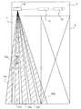
投光器16cによって、図2に示す検知範囲24cに投光され、投光器16cに対応する受光器20cがこの検知範囲24からの反射光を受光する。即ち、この検知範囲24c内に存在する物体を検出する。同様にして、投光器16d、受光器20dによって物体検出用の検知範囲24dが形成され、投光器16e、受光器20eによって物体検出用の検知範囲24eが形成され、投光器16f、受光器20fによって物体検出用の検知範囲24fが形成され、投光器16g、受光器20gによって物体検出用の検知範囲24gが形成されている。
【0025】
これら検知範囲24c乃至24gは、ドア面4a上にそれぞれ反射面を有している。これら反射面は、このセンサ14aが物体等を検出していないとき、投光器から投光された光線を反射する面である。特に、検知範囲24dは、図1に示すように、ドア4が閉位置にある状態において、ドア面4aの下端からドア面4aの中間までの間に反射面241dを有し、この反射面241dからセンサ14aまでの間に、検知範囲24dが形成されている。他の検知範囲24c、24e乃至24gも同様にドア面4a上に反射面を有している。これら反射面からセンサ14aまでの間に、投光された光や反射された光が通過する検知範囲24c、24e乃至24gが形成されている。
【0026】
図3(a)から明らかなように、検知範囲24c、24gでは、反射面の一部がドア面4aから外れている。これら検知範囲24c乃至24gは、開口2内に、ドア4の開閉方向に沿って配置されている。なお、図3(b)に示すように、ドア4が開かれた状態では、投光器16c乃至16gからの光線は、床面まで投光され、ここで反射され、対応する受光器20c乃至20gで受光される。
【0027】
このように投光器16c乃至16gと受光器20c乃至20gによって、第1の光学検出手段が構成されている。
【0028】
同様に、検知範囲24c乃至24gに対応する検知範囲26a乃至26eがセンサ14bによってドア4の反対側に形成されている。この場合、センサ14bの投光器16a乃至16e及び受光器20a乃至20eが使用され、投光器16f、16g、受光器20f、20gは使用されない。ドア4が開放されているとき、検知範囲24c乃至24gと、これらにそれぞれ対応する検知範囲26a乃至26eは、図3(b)に示すように、一部で重なり合っている。
【0029】
図1に示すように、ドア面4a上の反射面241dには、接触体、例えば表示板28aが取り付けられている。この表示板28aには、例えば通行者の手を近づけることを促すステッカー状のものを使用することもできるし、通常のタッチスイッチに設けられているカバーと同様な形状のものを使用することもできる。この表示板28aは、通常のタッチセンサが取り付けられる高さ位置に取り付けられている。ドア4の反対側の面4bにおける検知範囲261dにも表示板28bが設けられている。
【0030】
これら表示板28a、28bは、反射面241d、261dに取り付けられている。これら反射面241d、261dは、ドア面4a、4bにほぼ直線上に上下方向に沿って形成されているので、この反射面241d、261dに重ねて表示板28a、28bを取り付けることによって、その取付位置の調整が比較的容易に行える。
【0031】
センサ14aは、上述した投光器16a乃至16gの他に、もう一列の投光器を有している。これら投光器も、複数個、例えば7個設けられ、投光器16a乃至16gと同様なアーチ状に配置されている。また、受光器20a乃至20gの他に、もう一列の受光器も有している。これら受光器も、複数個、例えば7個設けられ、受光器20a乃至20gと同様なアーチ状に配置されている。
【0032】
これら別の一列の投光器と受光器とが、第2の光学検出手段を構成し、物体を検出するための複数、例えば15個の検知範囲30a乃至30oを形成している。これら検知範囲30a乃至30oは、図1及び図3(a)、(b)に示すように、床面に向かって伸びており、開口2の幅方向及び奥行き方向に5X3に配置されている。これら検知範囲30a乃至30oを形成するために、図示していないが、この別の一列の合計7個の投光器のうち5つの投光器からの投光光線は、光分散手段によって、開口2の奥行き方向に沿って3つに分散され、別の一列の7個の受光器のうち5つの受光器それぞれには、対応する3つの光線が収束手段によって収束されて、入射する。このように開口2の幅方向及び奥行き方向に多数の検知範囲を形成しているので、ドア4の近傍に立ち止まっている通行者を確実に検出することができる。
【0033】
図示していないが、センサ14aは、これら2列の投光器及び受光器の他に、これら投光器及び受光器の動作を制御し、かつ各受光器からの受光信号を適切に処理して、ドアコントローラ10に供給するための制御手段、例えばCPUやメモリも有している。
【0034】
センサ14bにおいても、同様に第2の光学検出手段によって複数の検知範囲が形成されているが、図3(a)、(b)から明らかなように、2X5の合計10個の検知範囲30a乃至30jが形成されている。
【0035】
このように構成された自動ドア装置では、ドア4が閉じている状態では、図3(a)に示すように、センサ14a、14bによって検知範囲24d、26dが有効とされている。即ち、検知範囲24d、26dで物体を検出可能とされている。他の検知範囲は全て無効とされ、物体を検出不能としている。有効とする方法としては、所定の投光器、例えば投光器16dのみに投光させる場合、或いは全ての投光器は投光するが、所定の受光器、例えば受光器20dの受光信号のみについて物体を検出しているか否かの検出処理をし、他の受光器の受光信号には検出処理をしない方法等がある。なお、ドア4が閉じていることは、ドア4の移動と共にパルス信号を発生するエンコーダの使用によって確認することもできるし、或いは検知範囲24c乃至24g及び検知範囲26a乃至26eの全てにおいてドア4が検出されていることによって、確認することもできる。
【0036】
この状態において、通行者がドア4に向かって進行し、表示板28aまたは28bに接触すると、検知範囲24dまたは26dにおいて、この接触が検出される。この検出によってドア4が開放される。
【0037】
ドア4が閉位置から移動を開始すると、図3(b)に示すように、検知範囲30a乃至30o、32a乃至32jが有効とされる。これによって、ドア4の近傍に通行者が存在することが検出される。ドア4が完全に開いた状態から所定時間が経過すると、通常、ドア4は再び閉じ始めるが、所定時間が経過しても、検知範囲30a乃至30o、32a乃至32jのいずれかにおいて、通行者がまだ検出されていると、ドア4は開位置に維持され、ドア4が閉じることはない。従って、ドア4に通行者が接触することがなく、通行者の安全を確保することができる。このように1つのセンサでありながら、起動用及び安全用に共用することができる。
【0038】
このドア4が開いている状態において、検知範囲24c乃至24g、26a乃至26eを有効としておけば、開口2上に立ち止まっている通行者を、これら検知範囲24c乃至24g、26a乃至26eによって検出することができる。従って、図3(a)、(b)に点線で示すように設けられる、開口2内に光線を引き通す開口2用のサポートセンサを除去することができる。このように3つのセンサ分の働きを1台のセンサによって行うことができる。
【0039】
なお、ドア4が閉じている状態で、検知範囲30a乃至30oまたは32a乃至32jにおいて通行者が検出されている状態において、検知範囲24d、26bを有効にすることもできる。このようにすると、例えば新聞紙等の飛来物が、検知範囲24d、26dにドア4の移動方向に沿って飛来しても、この飛来物を誤って検出することを防止することができる。
【0040】
このように、この自動ドア装置では、1台のセンサでありながら、複数のセンサを設けたのと同様に機能させることができる。しかも、センサ14aは、検知範囲24c乃至24g、26a乃至26eを形成するために、投光器16c乃至16gからの光線をドア面4aに向けて投光し、受光器20c乃至20gは、ドア面4aからの反射光線を受光するように光軸がドア面4aに向けられている。例えば、検知範囲24c乃至24g、26a乃至26eが、床面とセンサ14a、14bとの間に形成されていた場合、即ち、反射面241dや反射面261dに対応する反射面が床面に形成されていると、床面が雨等によって濡れている場合と、乾燥している場合とでは、光線の反射の状況が異なり、通行者がいないにも拘わらず、通行者がいると誤検出する可能性がある。或いは、晴天や雨天の場合にも、光線の反射状況が異なり、やはり誤検出する可能性がある。これに対し、ドア面4aに反射面241dや261dを形成していると、ドア面4は、気象の変化等によって反射の状況が大きく変化することが無いので、誤検出する可能性が減少する。
【0041】
図5に第2の実施の形態の自動ドア装置を示す。この自動ドア装置は、センサ14a、14bの設置位置が、第1の実施の形態の自動ドア装置とは異なる。即ち、センサ14a、14bは、図5に示すように無目8の幾分中央側に寄った位置に設けられている。そのため、表示板28a、28bが設けられる領域が、領域24bに変更されている。このようにセンサ14a、14bの取付位置を変更しているので、自動ドア装置の外観が良好になり、意匠的には有利になる。他の構成は、第1の実施の形態の自動ドア装置と同一であるので、詳細な説明は省略する。
【0042】
図6に第3の実施の形態の自動ドア装置を示す。この自動ドア装置は、両引きのスライドドア装置であって、2枚のドア104a、104bが設けられている。センサ14aは、無目8の外面側において、ほぼドア104a、104bの合わせ面上に位置するように設けられている。センサ14aによってドア面側に向かって形成される検知範囲は検知範囲24a乃至24gの7つである。従って、同一列に存在する全ての投光器16a乃至16g、受光器20a乃至20gが使用されている。検知範囲24c、24eに対応して、ドア104a、104bのドア面に表示板128a、128bが設けられている。他の構成は、第1の実施の形態の自動ドア装置と同一であるので、詳細な説明は省略する。
【0043】
上記の各実施の形態では、センサは、反射型のものを使用したが、焦電センサを使用することもできる。また、上記の各実施の形態では、センサは、ドアの両面側に設けたが、一方のドア面側にのみ設けることもできる。
【0044】
【発明の効果】
以上のように本発明によれば、1台のセンサしか使用していないにも拘わらず、起動センサとしても、安全センサとしても使用することができ、センサのコスト、ひいては自動ドア装置のコストを低減することができる。しかも、センサは、床面ではなくドア面との間に検知範囲を形成するので、気象条件の変化等があっても、誤検出を非常に低減することができる。
【図面の簡単な説明】
【図1】 本発明の第1実施形態の自動ドア装置の側面図である。
【図2】 図1の自動ドア装置の正面図である。
【図3】 図1の自動ドア装置におけるドアが閉じた状態と、開いた状態とにおける平面図である。
【図4】 図1の自動ドア装置において使用される投光器と受光器との配置を示す図である。
【図5】 本発明の第2の実施の形態の自動ドア装置の正面図である。
【図6】 本発明の第3の実施の形態の自動ドア装置の正面図である。
【符号の説明】
2 開口
4 ドア
14a 14b センサ
241d ドア面上の反射面 [0001]
BACKGROUND OF THE INVENTION
The present invention relates to an automatic door device and a sensor used therefor.
[0002]
[Prior art]
An automatic door device, for example, a sliding automatic door device, includes a type in which a touch sensor is provided as an activation sensor on a door and an opening is opened by the door when a passerby contacts the touch sensor. In this system, the opening is closed by a door when a predetermined time elapses after there is no passerby. However, if a passerby is standing in the opening when the door is about to close, the door that is about to close and the passerby may collide. Therefore, a support sensor is provided for detecting that a passerby is standing within the range of the opening width. When the support sensor detects a passerby after the opening is opened, the door is kept open.
[0003]
In this system, when a passer tries to pass through the opening while the door is about to close, the door being closed is not opened unless the passerby touches the touch switch moving with the door. Since this is not sufficiently recognized by ordinary passers-by, there is a possibility that the closing door will come into contact with the passer-by.
[0004]
Therefore, recently, another sensor is installed as a safety sensor in the eye above the opening, and when this safety sensor detects a passerby approaching the door, the door is opened and the passerby opens. Automatic doors that prevent contact with the door and improve safety have been proposed.
[0005]
[Problems to be solved by the invention]
However, in the above automatic door device, in addition to the touch switch, another safety sensor must be installed, the touch switch installed on the door surface, the support sensor passed through the opening, and installed invisible. This requires a total of three safety sensors, which increases the cost.
[0006]
SUMMARY OF THE INVENTION An object of the present invention is to provide an automatic door device that reduces costs without reducing traffic safety, and a touch sensor that prevents malfunctions by reducing costs used in such automatic door devices.
[0007]
[Means for Solving the Problems]
The automatic door device according to the present invention has a door that opens and closes an opening through which a passerby passes. This door may be a sliding type or a swing type. A sensor is provided above the opening. A contact body is provided on the door surface of the door. The sensor sets a first detection range for detecting the presence / absence of an object to an area including a part of the door surface, and sets a second detection range for detecting the presence / absence of an object in a depth direction away from the opening. To set an area aligned with the first detection range. The contact body is disposed within a first detection range on the door surface. Various types of contacts can be used, for example, a display board or a seal. In a state where it is detected that the door is in the open position, the first detection range is validated, and when an object is detected by the effective first detection range, the door is opened. In a state where it is detected that the door is located at a position other than the open position, the second detection range is validated, and when an object is detected by the effective second detection range, the door is opened. The sensor sets a plurality of second detection ranges, and when the door is located at a position other than the closed position, the plurality of second detection ranges in the vicinity of the opening is set in the depth direction or the Set along the width direction of the opening .
[0008]
In the automatic door device configured as described above, the first detection range is effective when the door is in the closed position. In this state, when a passerby contacts the contact body, this contact is detected by the sensor. Further, the second detection range is effective when the door is positioned other than the closed position. Accordingly, for example, when the door is moving from the closed position toward the open position, or when the door is moving from the open position toward the closed position, and there is a passerby within the second detection range, the passerby Is detected by the sensor. Although only one sensor is used as described above, it can be used as a touch sensor for activation using the first detection range and as a safety sensor using the second detection range. The cost of the automatic door device can be reduced. Moreover, the first detection range is formed on the door surface. The light reflection state on the door surface does not change as much as the floor surface even if the weather conditions change. Therefore, even if the weather conditions change, the sensor does not malfunction and the door can be prevented from malfunctioning. In addition, since detection is performed by a plurality of second detection ranges, the range that can be detected becomes wide. For example, even if a passerby stops near the opening, the passerby can be detected reliably, and the passerby is detected. An accident in which the passer-by cannot contact the door that the passer is trying to close can be prevented, and the safety of the passer-by can be ensured.
[0009]
The sensor can also validate the first detection range when the second detection range detects a passerby in a state where the door is in the closed position. For example, in the state where the second detection range does not detect a passerby, if the first detection range is enabled, it is blown by the wind even though the passerby has not yet approached the door. There is a possibility that the sensor mistakenly detects a flying object such as newspaper, and the door may be opened and closed unnecessarily. Alternatively, when the door is a transparent glass door, light may enter the first detection range from the door surface side opposite to the door surface on which the first detection range is formed. The sensor may malfunction. However, if a passerby is detected in the second detection range and the first detection range is enabled, the sensor will not detect a flying object by mistake, and the door is made of transparent glass. Also, the sensor does not malfunction due to light transmitted through the transparent door, and unnecessary opening and closing of the door can be prevented.
[0012]
Or a sensor can also provide multiple 1st detection ranges along the opening-and-closing direction of the door. In this case, it is desirable to enable the first detection range not only when the door is in the closed position but also when the door is located at a position other than the closed position. When configured in this manner, a plurality of first detection ranges existing along the door opening / closing direction can reliably detect a passerby that is stopped in the vicinity of the door or in the door opening. There is no need to separately provide a sensor for detecting a passerby stopped in the opening, and the cost can be further reduced.
[0013]
Alternatively, the sensor may be an optical reflection sensor in which a plurality of light projecting units that emit light rays and a plurality of light receiving units that receive reflected light beams of these light beams are arranged in an arch shape. In this case, the first detection range is set by a light projecting / receiving unit in the vicinity of the center disposed substantially perpendicular to the floor surface among the plurality of light projecting / receiving units. When configured in this way, the first detection range is arranged substantially perpendicular to the floor surface when viewed toward the door surface, so the contact body may be arranged substantially perpendicular to the floor surface, The installation position of the contact body relative to the door surface can be easily adjusted.
[0014]
Alternatively, the sensor may be an optical reflection sensor in which the light projecting / receiving units are arranged in an arch shape in the same manner as described above, and in this case, the first detection range is the floor surface of the plurality of light projecting / receiving units. On the other hand, it is set by the light projecting / receiving means in the vicinity of one end of the arch arranged obliquely. When comprised in this way, a sensor can be arrange | positioned in the center vicinity of a door opening, and it becomes advantageous on the design of an automatic door apparatus.
[0015]
The sensor according to the present invention has first and second optical detection means. As the optical detection means, one provided with a light projecting means and a light receiving means can be used. The first optical detection means detects the presence or absence of an object in a first detection range between the door surface including the contact body provided on the door surface of the door that opens and closes the opening and the first optical detection means. Arranged to detect. The second optical detection means is arranged to detect the presence or absence of an object in a second detection range from the floor surface in the depth direction away from the opening to the second optical detection means. When it is detected that the door is in the closed position closing the opening, when the second optical detection means detects an object , the first optical detection means is enabled and effective. When the first optical detection means detects an object, the door is opened. When it is detected that the door is located at a position other than the closed position, only the second optical detection means is enabled, and when the effective second optical detection means detects an object, The door is opened.
[0016]
In the sensor configured as described above, the first optical detection means is enabled in a state in which the second optical detection means detects the passerby within the second detection range, so that the passer-by is the door. The first optical detection means does not mistakenly detect a flying object that has come in when it is not approaching, and even if the door is transparent glass, the first optical detection means is detected by light transmitted through the transparent door. Does not malfunction, and unnecessary opening and closing of the door can be prevented. In addition, since the first detection range is formed between the door surface and the first optical detection means, it is possible to prevent the first optical detection means from malfunctioning due to changes in weather conditions. In addition, the deformation | transformation described in the automatic door apparatus is also possible in this sensor .
[0017]
DETAILED DESCRIPTION OF THE INVENTION
The automatic door device according to the first embodiment of the present invention has a
[0018]
As shown in FIGS. 1 and 2, an invisible 8 is provided above the
[0019]
For opening / closing control of the
[0020]
The
[0021]
The light receivers are also arranged in a plurality of rows, for example, two rows. As shown in FIG. 4, one row includes a plurality of, for example, seven
[0022]
The
[0023]
The
[0024]
The
[0025]
Each of the detection ranges 24c to 24g has a reflective surface on the
[0026]
As apparent from FIG. 3A, in the detection ranges 24c and 24g, a part of the reflection surface is separated from the
[0027]
Thus, the first optical detection means is constituted by the
[0028]
Similarly, detection ranges 26a to 26e corresponding to the detection ranges 24c to 24g are formed on the opposite side of the
[0029]
As shown in FIG. 1, a contact body, for example, a
[0030]
These
[0031]
The
[0032]
These another row of light projectors and light receivers constitute second optical detection means, and form a plurality of, for example, 15 detection ranges 30a to 30o for detecting an object. These detection ranges 30a to 30o, as shown in FIG. 1 and FIG. 3 (a), (b), the extend toward the floor surface, are arranged in 5 X 3 in the width direction and the depth direction of the
[0033]
Although not shown, the
[0034]
Also in
[0035]
In the automatic door device configured as described above, when the
[0036]
In this state, when the passerby moves toward the
[0037]
When the
[0038]
If the detection ranges 24c to 24g and 26a to 26e are made valid when the
[0039]
Note that the detection ranges 24d and 26b can be validated in a state where a passerby is detected in the detection ranges 30a to 30o or 32a to 32j with the
[0040]
Thus, this automatic door device can function in the same manner as a plurality of sensors, although it is a single sensor. Moreover, the
[0041]
FIG. 5 shows an automatic door device according to the second embodiment. This automatic door device is different from the automatic door device of the first embodiment in the installation positions of the
[0042]
FIG. 6 shows an automatic door device according to a third embodiment. This automatic door device is a double sliding door device, and is provided with two
[0043]
In each of the above embodiments, a reflective sensor is used, but a pyroelectric sensor can also be used. Moreover, in each said embodiment, although the sensor was provided in the both surfaces side of the door, it can also be provided only in one door surface side.
[0044]
【The invention's effect】
As described above, according to the present invention, although only one sensor is used, it can be used as a start sensor or a safety sensor, which reduces the cost of the sensor and thus the cost of the automatic door device. Can be reduced. Moreover, since the sensor forms a detection range between the door surface and not the floor surface, erroneous detection can be greatly reduced even if the weather conditions change.
[Brief description of the drawings]
FIG. 1 is a side view of an automatic door device according to a first embodiment of the present invention.
FIG. 2 is a front view of the automatic door device of FIG.
3 is a plan view of the automatic door device of FIG. 1 in a closed state and an open state.
4 is a diagram showing an arrangement of a projector and a light receiver used in the automatic door device of FIG. 1. FIG.
FIG. 5 is a front view of an automatic door device according to a second embodiment of the present invention.
FIG. 6 is a front view of an automatic door device according to a third embodiment of the present invention.
[Explanation of symbols]
2
Claims (6)
前記開口の上方に設けられたセンサと、
前記ドアのドア面に設けられた接触体とを、
具備し、
前記センサは、物体の有無を検知する第1の検知範囲を、前記ドアが開口を閉じている閉位置においてドア面を含む領域に設定し、かつ物体の有無を検知する第2の検知範囲を、前記開口から離れる奥行き方向で第1の検知範囲と並んでいる領域に設定し、
前記接触体は、前記ドアが前記閉位置にある状態において前記ドア面上の第1の検知範囲内に配置され、
前記ドアが前記閉位置にあることが検出されている状態において、第1の検知範囲を有効とし、有効な第1の検知範囲によって物体が検知されると、前記ドアを開き、
前記ドアが前記閉位置以外にあることが検出されている状態において、第2の検知範囲を有効とし、有効な第2の検知範囲によって物体が検知されると、前記ドアを開き、
前記センサは、第2の検知範囲を複数設定するものであって、前記ドアが前記閉位置以外の位置に位置する状態において、前記開口近傍の複数の第2の検知範囲を前記奥行き方向若しくは前記開口の幅方向に沿って設定する
自動ドア装置。A door that opens and closes an opening for passers-by;
A sensor provided above the opening;
A contact body provided on a door surface of the door,
Equipped ,
The sensor sets a first detection range for detecting the presence / absence of an object to a region including a door surface at a closed position where the door is closed, and a second detection range for detecting the presence / absence of an object. , And set in a region aligned with the first detection range in the depth direction away from the opening,
The contact body is disposed within a first detection range on the door surface in a state where the door is in the closed position,
In a state where it is detected that the door is in the closed position, the first detection range is enabled, and when an object is detected by the effective first detection range, the door is opened.
In a state where it is detected that the door is in a position other than the closed position, the second detection range is validated, and when an object is detected by the effective second detection range, the door is opened.
The sensor sets a plurality of second detection ranges, and when the door is located at a position other than the closed position, the plurality of second detection ranges in the vicinity of the opening is set in the depth direction or the Automatic door device set along the width direction of the opening .
光線を放射する複数の投光手段と、これら光線の反射光線を受光する複数の受光手段とを、それぞれアーチ状に配列した光学式の反射センサであり、第1の検知範囲は、前記複数の投受光手段のうち床面に対してほぼ垂直に配置されている中央付近の投受光手段によって設定されている自動ドア装置。The automatic door device according to claim 1, wherein the sensor is
An optical reflection sensor in which a plurality of light projecting means for emitting light rays and a plurality of light receiving means for receiving reflected light rays of these light rays are arranged in an arch shape, respectively, and a first detection range is the plurality of light detection means. An automatic door device that is set by a light projecting / receiving unit in the vicinity of the center of the light projecting / receiving unit disposed substantially perpendicular to the floor surface.
光線を放射する複数の投光手段と、これら光線の反射光線を受光する複数の受光手段とを、それぞれアーチ状に配列した光学式の反射センサであり、第1の検知範囲は、前記複数の投受光手段のうち床面に対して斜めに配置された前記アーチの一方の端部付近の投受光手段によって設定されている
自動ドア装置。The automatic door device according to claim 1, wherein the sensor is
An optical reflection sensor in which a plurality of light projecting means for emitting light rays and a plurality of light receiving means for receiving reflected light rays of these light rays are arranged in an arch shape, respectively, and a first detection range is the plurality of light detection means. An automatic door device that is set by a light projecting / receiving unit in the vicinity of one end of the arch arranged obliquely with respect to the floor surface among the light projecting / receiving unit.
第1の光学式検出手段は、開口を開閉するドアのドア面に設けられた接触体を含む前記ドア面から第1の光学式検出手段までの間の第1の検知範囲で物体の有無を検出するように配置され、
第2の光学式検出手段は、前記開口から離れる奥行き方向の床面から第2の光学式検出手段までの第2の検知範囲で物体の有無を検出するように配置され、
前記ドアが前記開口を閉じている閉位置にあることが検出されている状態において、第2の光学式検出手段が物体を検知しているとき、第1の光学式検出手段を有効とし、有効な第1の光学式検出手段が物体を検知したとき、前記ドアを開き、前記ドアが前記閉位置以外の位置に位置することが検出されている状態において、第2の光学式検出手段のみを有効とし、有効な第2の光学式検出手段が物体を検知したとき、前記ドアを開く
センサ。Having first and second optical detection means;
The first optical detection means detects the presence or absence of an object in a first detection range between the door surface including the contact body provided on the door surface of the door that opens and closes the opening and the first optical detection means. Arranged to detect,
The second optical detection means is arranged to detect the presence or absence of an object in a second detection range from the floor surface in the depth direction away from the opening to the second optical detection means,
When it is detected that the door is in the closed position closing the opening, when the second optical detection means detects an object , the first optical detection means is enabled and effective. When the first optical detection means detects an object, the door is opened, and in a state where it is detected that the door is located at a position other than the closed position, only the second optical detection means is used. A sensor that opens the door when enabled and when the effective second optical detection means detects an object .
Priority Applications (1)
| Application Number | Priority Date | Filing Date | Title |
|---|---|---|---|
| JP2002146515A JP3779644B2 (en) | 2002-05-21 | 2002-05-21 | Automatic door device and touch sensor thereof |
Applications Claiming Priority (1)
| Application Number | Priority Date | Filing Date | Title |
|---|---|---|---|
| JP2002146515A JP3779644B2 (en) | 2002-05-21 | 2002-05-21 | Automatic door device and touch sensor thereof |
Publications (3)
| Publication Number | Publication Date |
|---|---|
| JP2003336447A JP2003336447A (en) | 2003-11-28 |
| JP2003336447A5 JP2003336447A5 (en) | 2005-04-07 |
| JP3779644B2 true JP3779644B2 (en) | 2006-05-31 |
Family
ID=29705481
Family Applications (1)
| Application Number | Title | Priority Date | Filing Date |
|---|---|---|---|
| JP2002146515A Expired - Fee Related JP3779644B2 (en) | 2002-05-21 | 2002-05-21 | Automatic door device and touch sensor thereof |
Country Status (1)
| Country | Link |
|---|---|
| JP (1) | JP3779644B2 (en) |
Families Citing this family (18)
| Publication number | Priority date | Publication date | Assignee | Title |
|---|---|---|---|---|
| JP4731872B2 (en) * | 2004-10-12 | 2011-07-27 | 千蔵工業株式会社 | Automatic door opening and closing device |
| JP2006144244A (en) * | 2004-11-16 | 2006-06-08 | Optex Co Ltd | Automatic door sensor and opening-closing control method of automatic door |
| ES2572772T3 (en) * | 2005-01-21 | 2016-06-02 | Bea S.A. | Sensor for use in automatic doors |
| JP4969784B2 (en) * | 2005-02-04 | 2012-07-04 | 日本自動ドア株式会社 | Automatic door device |
| JP5092077B2 (en) * | 2006-06-23 | 2012-12-05 | オプテックス株式会社 | Object detection device for sheet shutter |
| USRE46672E1 (en) | 2006-07-13 | 2018-01-16 | Velodyne Lidar, Inc. | High definition LiDAR system |
| JP4859141B2 (en) * | 2007-10-10 | 2012-01-25 | オプテックス株式会社 | Active object detection device |
| JP2012001969A (en) * | 2010-06-16 | 2012-01-05 | Kyokko Electric Co Ltd | Automatic door and self-traveling unit for the same |
| DE102015121840A1 (en) * | 2015-12-15 | 2017-06-22 | Sick Ag | Optoelectronic sensor and method for detecting an object |
| US10627490B2 (en) | 2016-01-31 | 2020-04-21 | Velodyne Lidar, Inc. | Multiple pulse, LIDAR based 3-D imaging |
| WO2017164989A1 (en) | 2016-03-19 | 2017-09-28 | Velodyne Lidar, Inc. | Integrated illumination and detection for lidar based 3-d imaging |
| US10393877B2 (en) | 2016-06-01 | 2019-08-27 | Velodyne Lidar, Inc. | Multiple pixel scanning LIDAR |
| JP6778523B2 (en) * | 2016-07-01 | 2020-11-04 | トヨタホーム株式会社 | Building doorway switchgear |
| US10386465B2 (en) | 2017-03-31 | 2019-08-20 | Velodyne Lidar, Inc. | Integrated LIDAR illumination power control |
| WO2018208843A1 (en) | 2017-05-08 | 2018-11-15 | Velodyne Lidar, Inc. | Lidar data acquisition and control |
| US10712434B2 (en) | 2018-09-18 | 2020-07-14 | Velodyne Lidar, Inc. | Multi-channel LIDAR illumination driver |
| US11082010B2 (en) | 2018-11-06 | 2021-08-03 | Velodyne Lidar Usa, Inc. | Systems and methods for TIA base current detection and compensation |
| US11885958B2 (en) | 2019-01-07 | 2024-01-30 | Velodyne Lidar Usa, Inc. | Systems and methods for a dual axis resonant scanning mirror |
-
2002
- 2002-05-21 JP JP2002146515A patent/JP3779644B2/en not_active Expired - Fee Related
Also Published As
| Publication number | Publication date |
|---|---|
| JP2003336447A (en) | 2003-11-28 |
Similar Documents
| Publication | Publication Date | Title |
|---|---|---|
| JP3779644B2 (en) | Automatic door device and touch sensor thereof | |
| CA2502562C (en) | A remote body detection system for a door | |
| US6782660B2 (en) | Automatic door sensor | |
| US6051829A (en) | Safety detection system for sliding doors | |
| US8575538B2 (en) | Safety system for safeguarding a moving, guided motion element that blocks the movement of the guided motion element from triggering the saftey mode | |
| US20050200473A1 (en) | Passive infrared sensor and obstacle detection system used in the same | |
| WO2012073821A1 (en) | Sensor for automatic door | |
| JP2003336447A5 (en) | ||
| JP5150810B2 (en) | Automatic door opening and closing control device | |
| US6693273B1 (en) | Method and apparatus for monitoring a powered vent opening with a multifaceted sensor system | |
| JP4574678B2 (en) | Device for detecting foreign objects, particularly fingers, between an elevator car door having a glass door and an adjacent wall, and an elevator to which this device is attached | |
| JP3771126B2 (en) | Sliding automatic door | |
| JP4658354B2 (en) | Obstacle detection device and movable home fence device provided with the same | |
| KR101449888B1 (en) | Elevator door device | |
| JP4188362B2 (en) | Sliding automatic door | |
| US8471704B2 (en) | Door system comprising a sensor device for monitoring vertical door edges | |
| JP4265943B2 (en) | Automatic door device and automatic door sensor | |
| JP5903716B2 (en) | Active object detection device | |
| JP2001295547A (en) | Sensor for door | |
| JPH0682392A (en) | Damage detector for transparent body | |
| JP2003027835A (en) | Safety device for automatic door | |
| KR20100004974A (en) | Sliding door device | |
| JP2022100257A (en) | Automatic door device, sensor device for automatic door, control method of automatic door device, and control program of automatic door device | |
| KR19990049641A (en) | Elevator Door Safety Device | |
| JPH11228060A (en) | Safety device for elevator entrance |
Legal Events
| Date | Code | Title | Description |
|---|---|---|---|
| A521 | Request for written amendment filed |
Free format text: JAPANESE INTERMEDIATE CODE: A523 Effective date: 20040426 |
|
| A621 | Written request for application examination |
Free format text: JAPANESE INTERMEDIATE CODE: A621 Effective date: 20040426 |
|
| A711 | Notification of change in applicant |
Free format text: JAPANESE INTERMEDIATE CODE: A712 Effective date: 20041013 |
|
| A977 | Report on retrieval |
Free format text: JAPANESE INTERMEDIATE CODE: A971007 Effective date: 20051124 |
|
| A131 | Notification of reasons for refusal |
Free format text: JAPANESE INTERMEDIATE CODE: A131 Effective date: 20051206 |
|
| A521 | Request for written amendment filed |
Free format text: JAPANESE INTERMEDIATE CODE: A523 Effective date: 20060202 |
|
| TRDD | Decision of grant or rejection written | ||
| A01 | Written decision to grant a patent or to grant a registration (utility model) |
Free format text: JAPANESE INTERMEDIATE CODE: A01 Effective date: 20060228 |
|
| A61 | First payment of annual fees (during grant procedure) |
Free format text: JAPANESE INTERMEDIATE CODE: A61 Effective date: 20060302 |
|
| R150 | Certificate of patent or registration of utility model |
Ref document number: 3779644 Country of ref document: JP Free format text: JAPANESE INTERMEDIATE CODE: R150 Free format text: JAPANESE INTERMEDIATE CODE: R150 |
|
| FPAY | Renewal fee payment (event date is renewal date of database) |
Free format text: PAYMENT UNTIL: 20100310 Year of fee payment: 4 |
|
| FPAY | Renewal fee payment (event date is renewal date of database) |
Free format text: PAYMENT UNTIL: 20100310 Year of fee payment: 4 |
|
| FPAY | Renewal fee payment (event date is renewal date of database) |
Free format text: PAYMENT UNTIL: 20110310 Year of fee payment: 5 |
|
| FPAY | Renewal fee payment (event date is renewal date of database) |
Free format text: PAYMENT UNTIL: 20120310 Year of fee payment: 6 |
|
| FPAY | Renewal fee payment (event date is renewal date of database) |
Free format text: PAYMENT UNTIL: 20120310 Year of fee payment: 6 |
|
| FPAY | Renewal fee payment (event date is renewal date of database) |
Free format text: PAYMENT UNTIL: 20130310 Year of fee payment: 7 |
|
| FPAY | Renewal fee payment (event date is renewal date of database) |
Free format text: PAYMENT UNTIL: 20130310 Year of fee payment: 7 |
|
| S531 | Written request for registration of change of domicile |
Free format text: JAPANESE INTERMEDIATE CODE: R313531 |
|
| FPAY | Renewal fee payment (event date is renewal date of database) |
Free format text: PAYMENT UNTIL: 20130310 Year of fee payment: 7 |
|
| R350 | Written notification of registration of transfer |
Free format text: JAPANESE INTERMEDIATE CODE: R350 |
|
| FPAY | Renewal fee payment (event date is renewal date of database) |
Free format text: PAYMENT UNTIL: 20130310 Year of fee payment: 7 |
|
| FPAY | Renewal fee payment (event date is renewal date of database) |
Free format text: PAYMENT UNTIL: 20140310 Year of fee payment: 8 |
|
| R250 | Receipt of annual fees |
Free format text: JAPANESE INTERMEDIATE CODE: R250 |
|
| R250 | Receipt of annual fees |
Free format text: JAPANESE INTERMEDIATE CODE: R250 |
|
| R250 | Receipt of annual fees |
Free format text: JAPANESE INTERMEDIATE CODE: R250 |
|
| R250 | Receipt of annual fees |
Free format text: JAPANESE INTERMEDIATE CODE: R250 |
|
| R250 | Receipt of annual fees |
Free format text: JAPANESE INTERMEDIATE CODE: R250 |
|
| R250 | Receipt of annual fees |
Free format text: JAPANESE INTERMEDIATE CODE: R250 |
|
| LAPS | Cancellation because of no payment of annual fees |