JP3776735B2 - Image predictive decoding method, image predictive decoding device, image predictive encoding method, image predictive encoding device, and data storage medium - Google Patents
Image predictive decoding method, image predictive decoding device, image predictive encoding method, image predictive encoding device, and data storage medium Download PDFInfo
- Publication number
- JP3776735B2 JP3776735B2 JP2001048729A JP2001048729A JP3776735B2 JP 3776735 B2 JP3776735 B2 JP 3776735B2 JP 2001048729 A JP2001048729 A JP 2001048729A JP 2001048729 A JP2001048729 A JP 2001048729A JP 3776735 B2 JP3776735 B2 JP 3776735B2
- Authority
- JP
- Japan
- Prior art keywords
- image
- encoded
- data
- frame
- decoding
- Prior art date
- Legal status (The legal status is an assumption and is not a legal conclusion. Google has not performed a legal analysis and makes no representation as to the accuracy of the status listed.)
- Expired - Lifetime
Links
Images


Classifications
-
- G—PHYSICS
- G06—COMPUTING; CALCULATING OR COUNTING
- G06T—IMAGE DATA PROCESSING OR GENERATION, IN GENERAL
- G06T9/00—Image coding
- G06T9/004—Predictors, e.g. intraframe, interframe coding
Description
【0001】
【発明の属する技術分野】
本発明は、画像の予測復号化,符号化処理に関するもので、特に画像サイズが可変な場合における画像予測復号化方法,画像予測復号化装置,画像予測符号化方法,画像予測符号化装置,及びデータ記憶媒体に関するものである。
【0002】
【従来の技術】
デジタル画像を効率よく蓄積もしくは伝送するには、圧縮符号化する必要がある。デジタル画像を圧縮符号化するための方法として、JPEGやMPEGに代表される離散コサイン変換(DCT)のほかに、サブバンドやウェアブレット、フラクタルなどの波形符号化方法がある。また、画像間の冗長な信号を取り除くには、動き補償を用いた画像間予測を行い、差分信号を波形符号化する。
【0003】
ここでは、動き補償DCTに基づくMPEG方式について説明する。まず、符号化しようとする1フレームの入力画像を、複数の16×16画素の大きさのマクロブロックに分割して処理する。一つのマクロブロックを、さらに8×8画素の大きさの4つのブロックに分割し、8×8画素の大きさのブロックに対するDCTを施してから、量子化する。これはフレーム内符号化と呼ばれる。
【0004】
一方、ブロックマッチングをはじめとする動き検出方法で、量子化しようとする対象マクロブロックを含む当該フレームに対して時間的に隣接する別のフレームの中から、対象マクロブロックに対する誤差の最も小さい予測マクロブロックを検出し、該検出された動きに基づいて、過去の画像からの動き補償を行い、最適な予測ブロックを取得する。誤差の最も小さい予測マクロブロックへの動きを示す信号が動きベクトルである。予測マクロブロックを生成するために参照する画像を、以後、参照画像と呼ぶ。次に対象となるブロックと対応する予測ブロックとの差分を求め、該差分に対してDCTを施し、該DCT変換係数を量子化し、該量子化出力を動き情報とともに伝送もしくは蓄積する。これをフレーム間符号化と呼ぶ。
【0005】
また、このフレーム間符号化には、表示順で前にある画像からのみ予測するモードと、前にある画像と後ろにある画像の両方から予測するモードがある。前者を前方予測、後者を双方向予測と呼ぶ。
【0006】
受信側では、量子化された変換係数をもとの差分信号に復元した後に、該差分信号をもとに動きベクトルに基づいて予測ブロックを取得し、該予測ブロックと差分信号とを加算し、画像を再生する。なお、この従来の技術では、参照画像(予測画像を生成するために参照する画像)と、対象画像のサイズとが同じであることを前提にしている。
【0007】
最近、圧縮効率を向上させると同時に、画像を構成する物体単位の再生ができるように、画像を構成する物体を、任意形状の画像として、別々に圧縮符号化して伝送するようにしている。このような任意形状の画像の符号化,復号化では、画像のサイズが変化することがよくある。その一例としては、ボールがだんだん小さくなり,消えてしまう例が考えられる。また、場合によっては、画像(物体)のサイズがゼロになることもある。
【0008】
【発明が解決しようとする課題】
通常の場合には、参照画像は対象画像の直前にある再生画像である。参照画像のサイズがゼロの場合、参照画像には何も定義されないために、即ち予測符号化に用いる有意な画像データがないために、予測符号化することができなくなる。
【0009】
この場合にも、従来の技術を適用しようとすると、フレーム内符号化を行うしか方法はない。しかるに、フレーム内符号化を行うと、一般的に符号量が増え、圧縮率が低下してしまう。動画像のシーケンスの中で、画像が頻繁に消えたり(この場合、画像サイズはゼロになる)、現れたりする場合は、符号化効率が非常に悪くなる。たとえば、スポットライトがフラッシングする画像では、ライトが画像単位で消えたり,現れたりすると、すべてのライトの画像を、フレーム内符号化することになる。
【0010】
本発明は、上記のような問題点に鑑みてなされたもので、サイズ可変な画像に対し、参照画像のサイズがゼロになった場合、あるいは参照画像が完全に透過する場合でも、効率よく予測符号化を行うことのできる,画像予測復号化方法,画像予測復号化装置,画像予測符号化方法,画像予測符号化装置,及びデータ記憶媒体を提供することを目的としている。
【0011】
【課題を解決するための手段】
本発明に係る画像予測復号化方法は、 フレーム画像を符号化して得られた符号化フレームデータを予測復号化して再生フレーム画像を得る画像予測復号化方法であって、( i )フレーム画像を前方予測符号化して得られた符号化フレームデータを復号化する際には、復号化対象である第1のフレーム画像より先に復号化された、前方参照画像として参照され得るフレーム画像の符号化データである第2の符号化フレームデータが、復号化における参照に有意な画像符号化データを含むか否かを、前記第2の符号化フレームデータ内の、該第2の符号化フレームデータが前記参照に有意な画像符号化データを含むか否かを示す第1のフラグで判断し、前記第1のフラグが前記第2の符号化フレームデータが前記参照に有意な画像符号化データを含むことを示す場合には、前記第2の符号化フレームデータを復号化して得られた復号化フレーム画像を前方参照画像として選択し、前記第1のフラグが前記第2の符号化フレームデータが前記参照に有意な画像符号化データを含まないことを示す場合には、前記第2の符号化フレームデータよりも前に復号化された符号化フレームデータであって、前記参照に有意な画像符号化データを含む符号化フレームデータを復号化して得られた復号化フレーム画像を、前方参照画像として選択し、選択した前方参照画像を参照して予測画像を生成し、前記生成した予測画像と、前記第1の符号化フレームデータを復号化して得られた復号化フレーム画像とから再生フレーム画像を生成し、( ii )フレーム画像を双方向予測符号化して得られた符号化フレームデータを予測復号化する際には、復号化対象である第1のフレーム画像よりも先に復号化された、前方参照画像として参照され得るフレーム画像の符号化データである第2の符号化フレームデータと、前記第1のフレーム画像よりも先に復号化された、後方参照画像として参照され得るフレーム画像の符号化データである第3の符号化フレームデータとのそれぞれが、前記参照に有意な画像符号化データを含むか否かを、前記第2の符号化フレームデータ内の、該第2の符号化フレームデータが前記参照に有意な画像符号化データを含むか否かを示す第1のフラグと、前記第3の符号化フレームデータ内の、該第3の符号化フレームデータが前記参照に有意な画像符号化データを含むか否かを示す第2のフラグとで判断し、前記第1のフラグが前記第2の符号化フレームデータが前記参照に有意な画像符号化データを含むことを示し、かつ前記第2のフラグが前記第3の符号化フレームデータが前記参照に有意な画像符号化データを含まないことを示す場合には、前記第2の符号化フレームデータを復号化して得られた復号化フレーム画像を前方参照画像として選択し、前記第1のフラグが前記第2の符号化フレームデータが前記参照に有意な画像符号化データを含まないことを示し、かつ前記第2のフラグが前記第3の符号化フレームデータが前記参照に有意な画像符号化データを含むことを示す場合には、前記第3の符号化フレームデータを復号化して得られた復号化フレーム画像を後方参照画像として選択し、前記第1のフラグが前記第2の符号化フレームデータが前記参照に有意な画像符号化データを含むことを示し、かつ前記第2のフラグが前記第3の符号化フレームデータが前記参照に有意な画像符号化データを含むことを示す場合には、前記第2の符号化フレームデータを復号化して得られた復号化フレーム画像を前方参照画像として選択すると共に、前記第3の符号化フレームデータを復号化して得られた復号化フレーム画像を後方参照画像として選択し、選択した前方参照画像と選択した後方参照画像の少なくとも一方を参照して予測画像を生成し、生成した予測画像と、前記第1の符号化フレームデータを復号化して得られた復号化フレーム画像とから再生フレーム画像を生成する、ことを特徴とするものである。
【0012】
本発明に係る画像予測復号化装置は、フレーム画像を符号化して得られた符号化フレームデータを予測復号化して再生フレーム画像を得る画像予測復号化装置であって、復号化対象のフレーム画像を予測復号化する際に参照され得るフレーム画像の符号化データが、復号化における参照に有意な画像符号化データを含んでいるかどうかを判断する判断手段と、該判断手段での判断結果に基づいて、前記復号化対象のフレーム画像を予測復号化する際に参照する参照画像を選択する選択手段と、選択した参照画像を参照して予測画像を生成する予測画像生成手段と、生成した予測画像を用いて、前記復号化対象のフレーム画像を再生する再生手段とを備え、( i )フレーム画像を前方予測符号化して得られた符号化フレームデータを復号化するときには、前記判断手段は、復号化対象である第1のフレーム画像より先に復号化された、前方参照画像として参照され得るフレーム画像の符号化データである第2の符号化フレームデータが前記参照に有意な画像符号化データを含むか否かを、前記第2の符号化フレームデータ内の、該第2の符号化フレームデータが前記参照に有意な画像符号化データを含むか否かを示す第1のフラグで判断し、前記選択手段は、前記第1のフラグが前記第2の符号化フレームデータが前記参照に有意な画像符号化データを含むことを示す場合には、前記第2の符号化フレームデータを復号化して得られた復号化フレーム画像を前方参照画像として選択し、前記第1のフラグが前記第2の符号化フレームデータが前記参照に有意な画像符号化データを含まないことを示す場合には、前記第2の符号化フレームデータよりも前に復号化された符号化フレームデータであって、前記参照に有意な画像符号化データを含む符号化フレームデータを復号化して得られた復号化フレーム画像を、前方参照画像として選択し、前記予測画像生成手段は、選択した前方参照画像を参照して予測画像を生成し、前記再生手段は、生成した予測画像と、前記第1の符号化フレームデータを復号化して得られた復号化フレーム画像とから再生フレーム画像を生成し、( ii )フレーム画像を双方向予測符号化して得られた符号化フレームデータを予測復号化するときには、前記判断手段は、復号化対象である第1のフレーム画像よりも先に復号化された、前方参照画像として参照され得るフレーム画像の符号化データである第2の符号化フレームデータと、前記第1のフレーム画像よりも先に復号化された、後方参照画像として参照され得るフレーム画像の符号化データである第3の符号化フレーム画像データとのそれぞれが、前記参照に有意な画像符号化データを含むか否かを、前記第2の符号化フレームデータ内の、該第2の符号化フレームデータが前記参照に有意な画像符号化データを含むか否かを示す第1のフラグと、前記第3の符号化フレームデータ内の、該第3の符号化フレームデータが前記参照に有意な画像符号化データを含むか否かを示す第2のフラグとで判断し、前記選択手段は、前記第1のフラグが前記第2の符号化フレームデータが前記参照に有意な画像符号化データを含むことを示し、かつ前記第2のフラグが前記第3の符号化フレームデータが前記参照に有意な画像符号化データを含まないことを示す場合には、前記第2の符号化フレームデータを復号化して得られる復号化フレーム画像を前方参照画像として選択し、前記第1のフラグが前記第2の符号化フレームデータが前記参照に有意な画像符号化データを含まないことを示し、かつ前記第2のフラグが前記第3の符号化フレームデータが前記参照に有意な画像符号化データを含むことを示す場合には、前記第3の符号化フレームデータを復号化して得られた復号化フレーム画像を後方参照画像として選択し、前記第1のフラグが前記第2の符号化フレームデータが前記参照に有意な画像符号化データを含むことを示し、かつ前記第2のフラグが前記第3の符号化フレームデータが前記参照に有意な画像符号化データを含むことを示す場合には、前記第2の符号化フレームデータを復号化して得られた復号化フレーム画像を前方参照画像として選択すると共に、前記第3の符号化フレームデータを復号化して得られた復号化フレーム画像を後方参照画像として選択し、前記予測画像生成手段は、選択した前方参照画像と選択した後方参照画像の少なくとも一方を参照して予測画像を生成し、前記再生手段は、生成した予測画像と、前記第1の符号化フレームデータを復号化して得られた復号化フレーム画像とから再生フレーム画像を生成する、ことを特徴とするものである。
【0034】
【発明の実態の形態】
以下、本発明の実施の形態について、図1ないし図7を用いて説明する。
(実施の形態1)
図1は本発明の実施の形態1による画像予測復号化方法における,予測画像生成方法の流れ図を示す。図1を説明する前に、図2を用いて、本発明による画像予測復号化における画像予測の方法について説明する。本実施の形態1の画像予測復号化方法において用いる入力画像の画像サイズは、可変であり、場合によっては、サイズがゼロになることもある。
【0035】
図2(a) は、表示順に並んだ動画像の各画像201〜210を示す。画像201が最初の画面で、その次が、画像202, ……と、順に表示される。この順序を#1〜#10で示している。画像#1(201)は、最初の画像であり、フレーム内符号化を行う。本実施の形態1では、画像(1フレーム)を、複数の8×8画素の大きさのブロックに分割し、各8×8画素の大きさのブロックのDCTを施し、量子化する。量子化した係数を、可変長符号化する。復号化する場合は、該可変長符号化により得られた符号化データを可変長復号化し、該復号化により得られた量子化係数を逆量子化してから、逆DCT変換することにより、画像を再生する。次に、画像#2(202)を、すでに再生された画像#1(201)を参照して、フレーム間予測符号化する。
【0036】
本実施の形態1では、ブロックマッチングの動き検出方法で、画像#1(201)の中から対象ブロックに対し誤差の最も小さい予測ブロックを検出する。検出された、対象ブロックから予測ブロックへの動きに基づいて、再生された画像#1(201)から、対象ブロックの動き補償により、最適な予測ブロックを取得する。次に、対象となるブロックと、対応する予測ブロックとの差分を求め、該差分に対しDCTを施し、該DCT変換係数を量子化し、該量子化出力を、動き情報とともに、伝送もしくは蓄積する。ここで、再生された画像#1(201)は、画像#2(202)の参照画像となる。これを前方予測と呼ぶ。復号化する際には、逆量子化,及び逆DCTした差分に予測ブロックを加算し、画像を再生する。
【0037】
同様に、画像#3(203)と、画像#4(204)とは、矢印が示す参照画像から予測符号化を行う。また、画像#6(206),画像#8(208),画像#10(210)のように、2枚前の画像から予測することができる。また、画像#5(205),画像#7(207),画像#9(209)のように、前方予測のほかに、当該画像より後に表示される画像をも、参照することができる。
【0038】
このように当該画像より後に表示される画像を参照して予測を行うのを後方予測と呼ぶ。前方予測と後方予測をともにする場合は、これを双方向予測と呼ぶ。双方向予測では、前方予測モードと,後方予測モードと,前方後方予測を平均化する補間モードとがある。
【0039】
図2(b) は、図2(a) で予測した画像の伝送順序、すなわち復号化順序を示す。
画像#1(211)が、最初に復号化し、再生される。それを参照し、画像#2(212)を復号化する。画像#5(216)のような,双方向予測画像に対しては、予測に用いる参照画像を、先に復号化し、再生する必要がある。そのために、画像#6(215)は、画像#5(216)より先にある。同様に、画像#8(217)は、画像#7(218)より先に、画像#10(219)は、画像#9(220)より先に、伝送され、復号化され、再生される。
【0040】
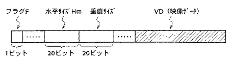
画像サイズ可変の画像を伝送する場合には、各画像に対して、サイズを伝送しなければならない。本実施の形態1では、画像のサイズを、画像の符号化データの先頭に記述し、水平,垂直のサイズHm,Vmを、夫々20ビットで表す。図7は、本実施の形態1における画像の符号化データを示し、ここで、この符号化データ(VD)内には、上記画像サイズのデータを示す水平,垂直のサイズHm,Vmの他に、動きベクトル、量子化幅、及び、DCT係数等が含まれる。
【0041】
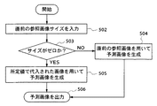
次に、図1の流れ図を用いて、本発明の実施の形態1による画像予測復号化方法における,予測画像生成方法について説明する。
予測画像を生成する際には、まず、ステップ102で、直前の参照画像のサイズを入力し、ステップ103で、参照画像のサイズがゼロかどうかを調べる。
【0042】
ここで、参照画像は、図2(a) に示す復号化順序において、常に、復号化の対象(符号化する場合は、符号化の対象)となる画像の前にある。該参照画像は、本実施の形態1による画像予測復号化方法においては、直前に再生される画像である。たとえば、図2(b) の画像#4(214)の参照画像は、その直前の画像#3(213)になる。但し、双方向予測で再生する画像は、予測に用いられないために、参照画像としては使わない。したがって、例えば、画像#8(217)の参照画像は、画像#6(215)になる。
【0043】
上記図1における,ステップ103の判定において、参照画像のサイズがゼロでなければ、ステップ104に進み、該ステップ104で、該直前の参照画像を用いて、予測画像を生成する。一方、上記ステップ103の判定において、参照画像のサイズがゼロであれば、ステップ105に進み、該ステップ105で、画像サイズがゼロでない最近に再生された画像を、参照画像として用いて、予測画像を生成する。ここでの,画像サイズがゼロでない最近に再生された画像の見つけ方については、図2(b) を用いて以下に説明する。
【0044】
画像#4(214)の予測画像を生成する場合において、画像#4(214)の前の画像#3(213)のサイズが、ゼロであるとし、画像#2(212)のサイズが、ゼロでないとする。この場合、画像#2(212)を参照して、画像#4(214)の予測画像を生成する。同様に、画像#6(215)の予測画像を生成する場合において、画像#3(213)と、画像#4(214)のサイズがゼロであるとすると、画像#2(212)を参照して、予測画像を生成する。
【0045】
ここで、予測画像の生成方法として、本実施の形態1では、MPEG1と同様に、ブロック単位の動き補償方法を用いる。
【0046】
図3は、本発明の実施の形態1による画像予測復号化装置のブロック図を示す。
本実施の形態1の画像予測復号化装置300は、画像サイズ可変な画像を所定の方法で圧縮符号化した画像データを受け、該画像データに対する予測復号化処理を施す構成となっている。
すなわち、この画像予測復号化装置300は、上記圧縮符号化した画像データを解析して、量子化幅やDCT係数をライン312に、動きベクトルをライン318に、画像サイズをライン321に出力するデータ解析器302と、該データ解析器302からの圧縮されたブロックのデータ(圧縮ブロック)を伸長処理により伸長ブロックに変換する復号化器303と、伸長ブロックと予測ブロックとを加算して再生ブロックを生成する加算器306とを有している。
【0047】
また、上記画像予測復号化装置300は、上記再生ブロックを格納するフレームメモリ部309と、上記動きベクトルに基づいてフレームメモリへのアクセスのためのアドレスを発生し、フレームメモリ内の画像から該アドレスに対応したブロックを上記予測ブロックとして求める予測画像生成器310とを有している。ここでは、この予測画像生成器310は、データ解析器302からの画像サイズに基づいて、参照されるべき有意な画像データが存在する最近に再生された1つの再生画像を参照画像として決定する動作も行うようになっている。なお、この参照画像の決定は、図3に点線で示すように、データ解析器302からの画像サイズに基づいてフレームメモリ部309を制御する制御器320を設け、該制御器320により、参照されるべき有意な画像データが存在する最近に再生された1つの再生画像が参照画像として選択されるようフレームメモリ部309を制御する構成としてもよい。
【0048】
また、ここでは、上記復号化器303は、上記データ解析器302からの圧縮ブロックに逆量子化処理を施す逆量子化器304と、ライン313からの該逆量子化器304の出力に対して、周波数領域信号を空間領域信号に変換する処理を施す逆離散コサイン変換器(IDCT)305とから構成されている。
また、図中301及び307はそれぞれ、本画像予測復号化装置300の入力端子及び出力端子である。
【0049】
以上のように構成された本実施の形態1による画像予測復号化装置について、以下、その動作を述べる。
画像サイズ可変な画像を、所定の方法で圧縮符号化した画像データ(符号化データ)を、入力端子301に入力する。本実施の形態1では、MPEG1と同じ動き補償DCT方法で圧縮符号化を行っており、上記符号化データには、上述したように、動きベクトル、量子化幅、DCT係数、及び、画像サイズのデータ,が含まれる。
【0050】
次に、データ解析器302にて、上記圧縮符号化した画像データを解析し、圧縮されたブロックのデータとして、量子化幅や、DCT係数を、ライン312を経由して、復号化器303に出力する。また、上記データ解析器302で解析した動きベクトルを、ライン318を経由して、予測画像生成器310に送り、同じく上記データ解析器302で解析した画像サイズを、ライン321を経由して、制御器320に出力する。
【0051】
復号化器303では、逆量子化器304と、逆離散コサイン変換器(逆DCT変換器)305により、上記圧縮されたブロックのデータ、即ち圧縮ブロックを伸長し、伸長ブロックに復元する。本実施の形態1では、逆量子化器304で、上記圧縮ブロックを逆量子化し、逆離散コサイン変換(IDCT)305で周波数領域信号を空間領域信号に変換し、伸長ブロック314を得る。予測画像生成器310では、ライン318を経由して送られた動きベクトルをもとに、フレームメモリ部309をアクセスするためのアドレス321を生成してこれをフレームメモリ部309に入力し、フレームメモリ部309に格納された画像の中から予測ブロック317を生成し、出力させる。該予測ブロック317,即ち319と、上記伸長したブロック314とを、加算器306に入力し、加算することにより、再生ブロック315を生成する。そして、該再生ブロック315を、出力端子307から出力させると同時に、ライン316を介して、フレームメモリ部309に格納する。なお、ここで、フレーム内符号化を行う場合には、予測ブロックのサンプル値は、すべてゼロになるものである。
【0052】
上記予測画像生成器310の動作は、図1の流れ図を用いて説明したものと同じである。即ち、まず、参照画像のサイズが予測画像生成器310に入力され、該予測画像生成器310において、参照画像が決定される。なお、この参照画像の決定は、制御器320を介して、ライン322を経由しての,参照画像のサイズがゼロであるかどうかの情報により、フレームメモリ部309を制御することにより行うことも可能である。
【0053】
図4は、本発明の実施の形態1による画像予測復号化装置におけるフレームメモリ部の一例である,フレームメモリバンク406のブロック図を示す。フレームメモリバンク406内には、3つのフレームメモリ401〜403が設けられている。再生された画像は、これらのフレームメモリ401〜403のうちのいずれかに格納される。また、予測画像を生成する時に、これらのフレームメモリ401〜403をアクセスする。
【0054】
本実施の形態1では、切り替えスイッチ404と、405とを具備している。
【0055】
スイッチ405は、ライン408(図3のライン316に相当)を介して入力される,再生された画像を、いずれのフレームメモリに格納するかを決めるためのもので、制御器320によって制御されて、即ち制御信号322に応じて、フレームメモリ401〜403を、順番に切り替える。すなわち、1番目の再生画像がフレームメモリ401に格納されたあとには、2番目の再生画像をフレームメモリ402に格納する。以下同様であるが、3番目の再生画像がフレームメモリ403に格納されたあとには、フレームメモリ401に切り替える。スイッチ404は、ライン407(図3のライン317に相当)を介して、予測画像生成器310に接続する。このスイッチ404も、制御器320によって、即ち制御信号322に応じて、所定の順番で切り替えられる。但し、その切り替え順序は、参照画像のサイズによって、変更される。たとえば、所定の順番に従えば、フレームメモリ402に接続し、予測画像を生成するところであっても、フレームメモリ402の画像サイズがゼロの場合、制御器320は一つ前のフレームメモリ401(これは、その画像サイズがゼロでないものとする)に接続するように、スイッチ404を制御する。このようにして、画像サイズがゼロでない参照画像から、予測画像を生成するようにすることができる。なお、スイッチ404は、同時に、複数のフレームメモリに接続してもよい。また、1枚の画像を再生するたびに、フレームメモリをリセットする装置では、再生される画像のサイズがゼロのときにはフレームメモリをリセットしないように、制御器320が管理することにより、サイズがゼロでない,最近に再生された画像を、フレームメモリに残すことができる。すなわち、フレームメモリを更新しないようにすることができる。
【0056】
なお、上記実施の形態1においては、ブロック動き補償離散コサイン変換方式を用いた場合について説明したが、本発明は、それ以外の予測方法(グローバル動き補償、任意格子状ブロック動き補償などを用いた予測方法)においても、適用可能である。また、参照画像として用いられる再生画像が1枚の場合について説明したが、複数枚の参照画像から、予測画像を生成する場合にも、同様に適用することができる。
【0057】
以上のような、本実施の形態1によれば、入力された直前の参照画像のサイズを検出し、該直前の参照画像のサイズが0でないときは、該直前の参照画像を用いて予測画像を生成し、該直前の参照画像のサイズが0のときは、サイズが0でない最近に再生された画像を用いて、予測画像を生成するようにしたので、圧縮効率の向上のため、画像を構成する物体を、物体単位で、別々に圧縮符号化して伝送する場合に、画像サイズが変化し、画像が消えてしまうような画像を、画像の予測復号化,予測符号化において参照画像として用いてしまうということがなくなり、残差信号(差分信号)を抑圧できる適正な予測復号化,予測符号化を行うことができる、という効果が得られる。
【0058】
(実施の形態2)
なお、上記実施の形態1では、参照画像のサイズが、ゼロかどうかを検出し、この検出した情報を用いて、参照画像を決定するようにした場合について述べたが、画像サイズがゼロであることが、別の指標(例えば、1ビットのフラグF,等)で示される場合には、その指標を用いて、制御を行うようにすることもでき、本実施の形態2は、このようにしたものである。
【0059】
即ち、本実施の形態2においては、対象画像の符号化データは、図9に示すように、画像サイズがゼロであること、即ち対応する参照画像が完全に透過するもので符号化データが存在しないこと,を示す1ビットのフラグFを、画像データの前の方,すなわち、画像サイズのデータを示す水平,垂直のサイズHm,Vmよりも前の方に設けたもので(ここで、画像サイズがゼロであれば、フラグFは“0”とする)、このような場合に、予測画像の生成方法を、図8に示すように、このフラグFを用いて、その制御を行うようにしたものである。
【0060】
次に、図8の流れ図を用いて、本発明の実施の形態2による画像予測復号化方法における,予測画像生成方法について説明する。
予測画像を生成する際には、まず、ステップ802で、直前の参照画像を入力し、ステップ803で、該参照画像のフラグFが“1”かどうかを調べる。ステップ803の判定において、該参照画像のフラグFが“1”であれば、これは、画像サイズがゼロではなく、言い換えれば、参照画像が完全に透過するものでなく、符号化データが存在するものであるので、ステップ804で、該直前の参照画像を用いて、予測画像を生成する。
【0061】
図8における,ステップ803の判定において、該参照画像のフラグFが“1”でなければ、ステップ805に進み、該ステップ805で、フラグFが“0”でない最近に再生された画像を、参照画像として用いて、予測画像を生成する。
このような本実施の形態2によれば、上記実施の形態1におけると同様に、画像を構成する物体を、物体単位で、別々に圧縮符号化して伝送する場合に、画像サイズが変化し、画像が消えてしまうような画像を、参照画像として用いてしまうということがなくなり、残差信号(差分信号)を抑圧できる適正な予測復号化,予測符号化を行うことができるとともに、対象画像の符号化データが、その先頭に、直前の再生画像に、参照されるべき有意な符号化データが存在するか否かを示すフラグをもつものとし、このフラグを検出して参照画像を決定するようにしたので、参照画像を決定する演算を、簡易に行うことができる効果が得られる。
【0062】
(実施の形態3)
図5は本発明の実施の形態3による画像予測復号化装置における,予測画像生成方法の流れ図を示す。本実施の形態3における予測画像生成方法は、図1に示す実施の形態1におけるとほとんど同じであり、異なる処理は、図1のステップ105に代わる、図5のステップ505である。ステップ505では、参照画像がゼロのとき、あるいは参照画像が完全に透過するときに、(あるいは画像のフラグFが“0”であるときに)、予測画像として、所定の値を代入してなるもの,即ち所定の値を有する予測画像を生成する。
【0063】
本実施の形態3では、これを灰色,即ち輝度信号と色差信号の値がともに128,とする。その結果、本実施の形態3では、符号化する時には、符号化の対象となるブロックから、灰色のブロックを引き算し、復号化する時には、復号化の対象となるブロックに、灰色のブロックを加算する。なお、上記所定の値は、可変の値とし、これを符号化部から復号化部に伝送し、これを用いて、予測画像を生成するようにしてもよい。
【0064】
このような本実施の形態3によれば、画像を構成する物体を、物体単位で、別々に圧縮符号化して伝送する場合に、画像サイズが変化し、画像が消えてしまうような画像を、参照画像として用いてしまうということがなくなり、残差信号(差分信号)を抑圧できる適正な予測復号化,予測符号化を行うことができるとともに、参照画像のサイズが0であることを検出したとき、即ち参照画像が完全に透過するときに、予測画像として、所定の値を有する予測画像を生成するようにしたので、上記実施の形態1におけると同様の効果を得ることができ、さらに、予測画像を容易に生成することができる効果が得られる。
【0065】
(実施の形態4)
図10は本発明の実施の形態4による画像予測復号化装置における,予測画像生成方法の流れ図を示す。本実施の形態4における予測画像生成方法は、図8に示す実施の形態2におけるとほとんど同じであり、異なる処理は、図8のステップ805に代わる、図10のステップ1005である。ステップ1005では、参照画像の画像のフラグFが“0”であるときに、予測画像として、所定の値を代入してなるもの,即ち所定の値を有する予測画像を生成する。
【0066】
このような本実施の形態4によれば、画像を構成する物体を、物体単位で、別々に圧縮符号化して伝送する場合に、画像サイズが変化し、画像が消えてしまうような画像を、参照画像として用いてしまうということがなくなり、残差信号(差分信号)を抑圧できる適正な予測復号化,予測符号化を行うことができるとともに、対象画像の符号化データが、その先頭に、直前の再生画像に参照されるべき有意な符号化データが存在するか否かを示すフラグをもつものとし、このフラグが“0”であることを検出したときに、予測画像として、所定の値を有する予測画像を生成するようにしたので、上記実施の形態2におけると同様の効果を得ることができ、さらに、予測画像を容易に生成することができる効果が得られる。
【0067】
(実施の形態5)
図6は、本発明の実施の形態5による双方向予測を用いた、画像予測復号化方法における,予測画像生成方法の流れ図を示す。以下、本実施の形態5の特徴である双方向予測の場合について、参照画像サイズがゼロの場合、即ち参照画像が完全に透過する場合の処理について説明する。
【0068】
即ち、図6に示されるように、まず、ステップ602において、前方,後方の参照画像(両方向の参照画像)のサイズを入力する。図2(a) の画像#5(205)は、双方向予測画像で、前方参照画像は、画像#4(204)であり、後方参照画像は、画像#6(206)である。
【0069】
そして、ステップ603とステップ604によって、前方,及び後方の参照画像のサイズがともにゼロの場合、ステップ605において、所定の値を代入してなる画像,即ち所定の値を有する画像を、予測画像とする。
ステップ603とステップ604によって、前方参照画像のサイズがゼロで、後方参照画像のサイズがゼロでない場合、ステップ606において、後方参照画像のみを用いて、予測画像を生成する。
【0070】
次に、ステップ603とステップ607によって、前方参照画像のサイズがゼロでなくて、後方参照画像のサイズがゼロである場合、ステップ608において、前方参照画像のみを用いて、予測画像を生成する。
ステップ603とステップ607によって、前方後方参照画像のサイズがともにゼロでない場合、ステップ609において、両方向の参照画像を用いて、予測画像を生成する。
【0071】
そして、ステップ610で、生成した予測画像を出力し、符号化部では、該予測画像を、対象画像から引き算し、復号化部では、該予測画像を、対象画像の差分に、加算する。このようにして、残差信号(差分信号)を抑圧することができる。
【0072】
このような本実施の形態5によれば、画像を構成する物体を、物体単位で、別々に圧縮符号化して伝送する場合において、両方向参照画像を用いて予測画像を生成する場合に、画像サイズが変化し、画像が消えてしまうような画像を、参照画像として用いてしまうということがなくなり、残差信号(差分信号)を抑圧できる適正な予測復号化,予測符号化を行うことができるとともに、予測画像として、所定の値を有する予測画像を生成するようにしたので、予測画像を容易に生成することができる効果が得られる。
【0073】
(実施の形態6)
図11は本発明の実施の形態6による両方向予測を用いた、画像予測復号化方法における,予測画像生成方法の流れ図を示す。以下、本実施の形態6は、上記実施の形態2,4の、上記実施の形態1,3に対する関係と同じである。即ち、本実施の形態6は、図6に示す実施の形態5における、図6のステップ603,604,607における「サイズがゼロか?」を、「のフラグFが“0”か?」に変更して、それぞれ図11のステップ1103,1104,1107としたものである。
【0074】
従って、このような本実施の形態6によれば、画像を構成する物体を、物体単位で、別々に圧縮符号化して伝送する場合において、両方向参照画像を用いて予測画像を生成する場合に、画像サイズが変化し、画像が消えてしまうような画像を、参照画像として用いてしまうということがなくなり、残差信号(差分信号)を抑圧できる適正な予測復号化,予測符号化を行うことができるとともに、前方,後方の両参照画像のフラグFが0であることを検出したときに、所定の値を有する予測画像を生成するようにしたので、画像サイズが変化し、画像が消えてしまうような画像の検出を容易に行うことができ、さらには、予測画像を容易に生成することができる効果が得られる。
以下、さらなる本発明の実施の形態7,8として画像予測符号化装置について説明する。
【0075】
(実施の形態7)
図12は本発明の実施の形態7による画像予測符号化装置のブロック図を示す。
この画像予測符号化装置1000は、輝度信号及び色差信号からなるテクスチャー信号に対する予測符号化を行うテクスチャー符号化部1100と、形状信号に対する予測符号化を行う形状符号化部1200とを有している。
【0076】
上記テクスチャー符号化部1100は、1フレームのテクスチャー信号を、符号化処理の単位である16×16画素の大きさのマクロブロック毎に分割して出力するブロック化器1110と、符号化処理の対象となる対象ブロックと、これに対応する予測ブロックとの差分を求める減算器1160と、該差分を圧縮符号化する圧縮符号化器1120と、該圧縮符号化器1120の出力を伸長復号する局所復号化器1130とを有している。ここで、上記圧縮符号化器1120は、上記差分に対してDCTを施す離散コサイン変換器1121と、DCT変換係数を量子化する量子化器1122とから構成されている。また上記局所復号化器1130は、上記量子化器1122の出力を逆量子化する逆量子化器1131と、該逆量子化器1131の出力に対して、周波数領域信号を空間領域信号に変換する逆DCTを施す逆離散コサイン変換器1132とから構成されている。
【0077】
また、上記テクスチャー符号化部1100は、上記逆離散コサイン変換器1132の出力である伸長ブロックと上記予測ブロックとを加算して再生ブロックを生成する加算器1170と、該再生ブロックを格納するフレームメモリ部(FM1)1140と、所定の動き検出法により検出された動き情報に基づいて、該フレームメモリ部1140に格納された画像から動き補償により対象ブロックに対応する予測ブロックを取得する予測画像生成器1150とを有している。
【0078】
この予測画像生成器1150は、ブロック化器1110の出力から得られる画像サイズに基づいて、フレームメモリブロック1140に格納されている再生画像から、予測ブロック(予測画像)を生成する際に参照する参照画像を設定する動作をも行うようになっている。
【0079】
一方、上記形状符号化部1200は、1フレームの形状信号を、符号化処理の単位である16×16画素の大きさのマクロブロック毎に分割して出力するブロック化器1210と、符号化処理の対象となる対象ブロックと、これに対応する予測ブロックとの差分を求める減算器1260と、該差分を所定の符号化方法により符号化する形状符号化器1220と、該形状符号化器1220の出力を上記所定の符号化方法に対応する復号化方法により復号する形状復号化器1230とを有している。ここで、上記形状符号化器1120は、、四分木やチェイン符号化方法等により上記減算器1260の出力を符号化する構成となっている。
【0080】
また、上記形状符号化部1200は、上記形状復号化器1230の出力である復号ブロックと上記予測ブロックとを加算して再生ブロックを生成する加算器1270と、該加算器1270から出力される復号ブロックを格納するフレームメモリ部(FM2)1240と、所定の動き検出法により検出された動き情報に基づいて、該フレームメモリ部1240に格納された形状情報から動き補償により対象ブロックに対応する予測ブロックを取得する予測画像生成器1250とを有している。ここでは、該予測画像生成器1250は、上記ブロック化器1210の出力から得られる画像サイズに基づいて、フレームメモリブロック1240に格納されている再生画像から、予測ブロック(予測画像)を生成する際に参照する参照画像を決定する動作をも行うようになっている。
【0081】
なお、上記各符号化部1100及び1200での参照画像の決定は、図12に点線で示すように、上記再生ブロックに基づいて形状検出を行う形状検出器1280を設け、この形状検出器1280から出力される形状検出出力により上記各フレームメモリ部(FM1,FM2)1140,1240を制御することにより行うようにしてもよい。この場合における形状検出出力によるフレームメモリ部の制御は、上記実施の形態1における制御器320によるフレームメモリ部309の制御と全く同様に行われる。また、この場合には、上記形状検出出力は、可変長符号化器1010に供給され、テクスチャー信号及び形状信号の符号化データとともに伝送されることとなる。
【0082】
また、上記画像予測符号化装置1000は、上記テクスチャー符号化部1100の出力である符号化テクスチャー信号、上記形状符号化部1200の出力である符号化形状信号及び形状検出出力を可変長符号化し、多重化して出力する可変長符号化器1010を有している。
なお、図中、1001はテクスチャー信号の入力端子、1002は形状信号の入力端子、1003は符号化データの出力端子である。
【0083】
次に動作について説明する。
この画像予測符号化装置1000にテクスチャー信号(輝度・色差信号)及び形状信号が入力されると、上記テクスチャー信号及び形状信号はそれぞれ対応する符号化部1100,1200おけるブロック器1110,1210にて符号化処理の単位となるマクロブロックに分割され、各マクロブロック毎に予測符号化処理が行われる。
【0084】
テクスチャー信号符号化部1100では、対象ブロックと予測ブロックとの差分が減算器1160により求められ、DCT器1121にてこの差分がDCT係数に変換され、さらにこのDCT係数が量子化器1122にて量子化係数に変換される。そしてこの量子化係数は可変長符号化器1010に出力される。
【0085】
上記量子化係数は逆量子化器1131にてDCT係数に逆変換され、さらにこのDCT係数は、IDCT器1130での周波数領域のデータを空間領域のデータに変換する処理により、上記対象ブロックに対応する伸長ブロックに変換される。さらにこの伸長ブロックと上記予測ブロックとが加算器1170により加算されて再生ブロックが生成される。そしてこの再生ブロックは、フレームメモリ部1140に格納される。このとき、上記予測画像生成器1150では、所定の動き検出法により検出された動き情報に基づいて、該フレームメモリ部1140に格納された画像から動き補償により対象ブロックに対応する予測ブロックが生成する処理が行われている。また、この予測画像生成器1150では、ブロック化器1110の出力から得られる画像サイズに基づいて、フレームメモリブロック1140に格納されている再生画像から、参照されるべき有意な画像データが存在する最近に再生された1つの再生画像を参照画像として決定する。なお、この参照画像の決定は、形状検出器1280が設けられている場合には、その出力である形状検出出力,つまり通常参照されるべき再生画像のサイズがゼロであるかどうかの情報により、フレームメモリ部1140を制御することにより行うことも可能である。
【0086】
また、上記テクスチャー符号化部1100の処理と並行して、形状符号化部1200では、形状信号に対する予測符号化処理が、上記テクスチャー信号の予測符号化処理とほぼ同様に行われる。つまり、対象ブロックと予測ブロックとの差分が減算器1260により求められ、形状符号化器1220にてこの差分が四分木やチェイン符号化方法等の方法で符号化されて上記可変長符号化器1010に出力される。また上記形状符号化器1220からの形状符号化信号は形状復号化器1230により復元され、復元ブロックと予測ブロックが加算器1270により加算されて再生ブロックが生成される。
【0087】
この加算器1270から出力される再生ブロックはフレームメモリ部1240に格納され、上記予測画像生成器1250では、所定の動き検出法により検出された動き情報に基づいて、該フレームメモリ部1240に格納された形状情報から動き補償により対象ブロックに対応する予測ブロックが生成される。また、この予測画像生成器1250では、ブロック化器1210の出力から得られる画像サイズに基づいて、フレームメモリブロック1240に格納されている再生画像から、参照されるべき有意な画像データが存在する最近に再生された1つの再生画像を参照画像として決定する。
【0088】
なお、この参照画像の決定は、形状検出器1280が設けられている場合には、その出力である形状検出出力,つまり通常参照されるべき再生画像のサイズがゼロであるかどうかの情報により、フレームメモリ部1240を制御することにより行うことも可能である。また、この場合、上記再生ブロックは形状検出器1280に入力され、ここで形状検出が行われる。例えば、形状信号が2値信号である場合には、形状データとしての白データ及び黒データのうちの黒データしかない場合には、再生形状はなにもないこととなる。このとき、このブロックの形状信号に対応するテクスチャー信号も存在しないこととなる。この場合には、上述したように、形状検出器1280からは、符号化データなしを示すフラグあるいは画像サイズゼロのデータが形状検出出力として、上記各フレームメモリ部1140,1240及び上記可変長符号化器1010に出力される。各フレームメモリ部1140,1240では、上記形状検出出力により、上記実施の形態1における制御器320によるフレームメモリ309の制御と同様の制御が行われる。
【0089】
このように本実施の形態7では、各符号化部1100及び1200にて、ブロック化器1110,1210の出力から得られる画像サイズに基づいて、フレームメモリブロック1140,1210に格納されている再生画像から、参照されるべき有意な画像データが存在する最近に再生された1つの再生画像を参照画像として決定するので、画像を構成する物体を、物体単位で別々に圧縮符号化して伝送する場合に、画像サイズが変化し、画像がきえてしまうような画像を、画像の予測符号化において参照画像として用いてしまうということがなくなり、適正な予測符号化を行うことができるという効果が得られる。また、この実施の形態7の画像予測符号化装置により予測符号化された符号化データは、実施の形態2の画像予測復号化装置により正しく復号化することができる。
【0090】
また、形状検出器1280を有する場合には、形状符号化部1200にて、入力された対象ブロックに対応する参照画像が存在するか否かの判定を、形状信号の再生ブロックの形状を検出することにより行い、再生ブロックの形状がないときには、テクスチャー符号化部及び形状符号化部では、対象ブロックに対応する再生ブロックに代えて、最近に再生された形状を有する再生ブロックを用いて予測ブロックを生成するので、画像を構成する物体を、物体単位で別々に圧縮符号化して伝送する場合に、画像サイズが変化し、画像がきえてしまうような画像を、画像の予測符号化において参照画像として用いてしまうということがなくなり、残差信号(差分信号)を抑圧できる適正な予測符号化を行うことができるという効果が得られる。この場合には、実施の形態7の画像予測符号化装置により予測符号化された符号化データは、実施の形態2の画像予測復号化装置により正しく復号化することができる。つまり、該画像予測復号化装置では、データ解析器302が上記形状検出出力に基づいてフレームメモリブロック309を制御することとなり、これにより、物体単位で予測符号化された符号化データを復号する際、画像サイズが変化し、画像がきえてしまうような画像を、画像の予測復号化において参照画像として用いてしまうということがなくなり、適正な予測復号化を行うことができる。
【0091】
なお、上記実施の形態7では、予測画像生成器1150,1250による参照画像としての再生画像の選択、あるいは形状検出出力によるフレームメモリ部1140及び1240の制御は、上記実施の形態1における予測画像生成器1150,1250による参照画像としての再生画像の選択、あるいは制御器320によるフレームメモリ部309の制御と全く同様に行われる場合について示したが、これに限るものではない。
【0092】
例えば、対象フレームの直前のフレームに参照されるべき画像データが存在しない場合には、実施の形態3のように、予測画像として、所定の値を有する予測画像を生成するものでもよく、この場合は、画像予測符号化装置に対応する画像予測復号化装置として、上記実施の形態3の画像予測復号化処理を行う装置を用いることができる。
【0093】
また、上記実施の形態7における予測処理は、実施の形態5のように、双方向予測処理でもよく、この場合は、画像予測符号化装置に対応する画像予測復号化装置として、上記実施の形態5の画像予測復号化処理を行う装置を用いることができる。
【0094】
(実施の形態8)
図13は本発明の実施の形態8による画像予測符号化装置のブロック図を示す。
この画像予測復号化装置1000aは、輝度信号及び色差信号からなるテクスチャー信号に対する予測符号化を行うテクスチャー符号化部1100aと、形状信号に対する予測符号化を行う形状符号化部1200aとを有している。
【0095】
ここで、上記テクスチャー符号化部1100aは、上記実施の形態7のテクスチャー符号化部1100の構成に加えて、ブロック化器1110の前段に、テクスチャー信号を制御信号によりブロック化器1110と接地との間で切り替えてその一方に供給する切替スイッチ1190を有する構成となっている。
【0096】
また、上記形状符号化部1200aは、上記実施の形態7の形状符号化部1200における形状検出器1280は有しておらず、ブロック化器1210の前段に、形状信号を制御信号によりブロック化器1210と接地との間で切り替えてその一方に供給する切替スイッチ1290を有している点で、上記実施の形態7のものと異なっている。
【0097】
また、上記画像予測復号化装置1000aは、形状信号を受け、その形状検出出力を上記制御信号として各切替スイッチ1190,1290に出力する形状検出器1020を有している。ここで、上記各切替スイッチは、形状検出器1020での形状検出の結果、入力される形状信号が形状を有しないものであるときには、その形状検出出力により、入力されるテクスチャー信号及び形状信号が接地側に入力され、一方対入力される形状信号が形状を有するものであるときには、テクスチャー信号及び形状信号が各ブロック化器1110,1210に入力されるようこれらの信号の切替を行うようになっている。なお、上記形状検出出力は、可変長符号化器1010にて、各符号化部1100a,1200aからの符号化データとともに可変長符号化処理が施されるようになっている。
【0098】
次にこの実施の形態8の画像予測復号化装置の動作について簡単に説明する。このような構成の実施の形態8の画像予測復号化装置1000aでは、上記形状検出器1020による切替スイッチの制御以外は、上記実施の形態7と同様な予測復号化動作が行われる。
【0099】
つまり、この画像予測復号化装置1000aでは、テクスチャー信号及び形状信号が入力されると、形状検出器1020にて、入力される形状信号が形状を有するものであるか否かの検出が行われる。この検出の結果、形状信号が形状を有しないものであるときには、上記形状検出器1020の出力により切替スイッチ1190及び1290が制御され、入力されるテクスチャー信号及び形状信号が接地側に供給される。つまりこのときには、形状信号及びテクスチャー信号に対する予測符号化処理は行われず、形状検出出力が可変長符号化器1010に供給される。
【0100】
一方、上記検出の結果、入力される形状信号が形状を有するものであるときには、上記形状検出器1020の出力により切替スイッチ1190及び1290が制御され、テクスチャー信号及び形状信号が各ブロック化器1110,1210に入力され、それぞれ予測符号化処理が施される。そして、各符号化部1100a及び1200aの出力とともに上記形状検出出力が可変長符号化器1010に出力される。
【0101】
このように本実施の形態8では、入力された形状信号が形状を有するものであるか否かを判定する形状検出器1020を備え、形状信号が形状を有するものである場合には、テクスチャー信号及び形状信号に対する予測符号化を行い、形状信号が形状を有するものでない場合には、テクスチャー信号及び形状信号に対する予測符号化を行わないようにしたので、画像を構成する物体を、物体単位で別々に圧縮符号化して伝送する場合に、画像サイズが変化し、画像がきえてしまうような画像を、画像の予測符号化において参照画像として用いてしまうということがなくなり、残差信号(差分信号)を抑圧できる適正な予測符号化を行うことができる。
【0102】
また、上記形状検出器での検出出力を符号化して伝送するようにしたので、画像予測復号化装置では、この検出出力を同期信号して用いて、つまり、画像サイズが小さくなって画像が消えている間は、この画像に対応する符号化データの再生を停止するようにして、画像サイズが変化し、画像がきえてしまうような画像に対する予測復号化処理を適正に行うことができる。
【0103】
さらに、上記各実施の形態で示した画像予測復号化方法あるいは装置,及び画像予測符号化方法あるいは装置の構成を実現するためのプログラムを、フロッピーディスク等のデータ記録媒体に記録するようにすることにより、上記各実施の形態で示した処理を、独立したコンピュータシステムにおいて簡単に実施することが可能となる。
【0104】
図14は、上記各実施の形態における予測復号化処理あるいは予測符号化処理を、これらの信号処理に対応したプログラムを格納したフロッピーディスクを用いて、コンピュータシステムにより実施する場合を説明するための図である。
図14(a) は、フロッピーディスクFDの正面からみた外観、断面構造、及び記録媒体であるフロッピーディスク本体を示し、図14(b) は、フロッピーディスク本体Dの物理フォーマットの例を示している。フロッピーディスク本体DはケースFC内に内蔵され、該ディスク本体Dの表面には、同心円状に外周から内周に向かって複数のトラックTrが形成され、各トラックは角度方向に16のセクタSeに分割されている。従って、上記プログラムを格納したフロッピーディスク本体Dでは、上記フロッピーディスク本体D上に割り当てられた領域に、上記プログラムとしてのデータが記録されている。
【0105】
また、図14(c) は、フロッピーディスクFDに対する上記プログラムの記録再生を行うための構成を示す。上記プログラムをフロッピーディスクFDに記録する場合は、コンピュータシステムCsから上記プログラムとしてのデータをフロッピーディスクドライブFDDを介してフロッピディスクFDに書き込む。また、フロッピーディスクFD内のプログラムにより、上記画像伝送方法あるいは画像復号化装置をコンピュータシステムCs中に構築する場合は、フロッピーディスクドライブFDDによりプログラムをフロッピーディスクFDから読み出し、コンピュータシステムCsに転送する。
【0106】
なお、上記説明では、データ記録媒体として、上記各実施の形態における予測復号化処理あるいは予測符号化処理を行うためのプログラムを格納したものを挙げたが、データ記録媒体としては、上記各実施の形態における画像の符号化データを格納したものも挙げられる。
【0107】
また、上記説明では、データ記録媒体としてフロッピーディスクを用いたコンピュータシステムによる画像処理の説明を行ったが、この画像処理は、光ディスクを用いても同様に行うことができる。また、記録媒体はこれに限らず、ICカード、ROMカセット等、プログラムを記録できるものであれば同様に上記画像処理を実施することができる。
【0108】
【発明の効果】
以上のように本発明にかかる画像予測復号化方法,画像予測復号化装置,画像予測符号化方法,及び画像予測符号化装置によれば、参照画像のサイズがゼロのとき、あるいは参照画像が完全に透過するとき、あるいは、参照画像のサイズがゼロであることを示す画像データ中のフラグを検出したときに、画像サイズがゼロでないほかの再生画像を用いて、予測復号化を行うようにしたので、圧縮効率の向上のため、画像を構成する物体を、物体単位で、別々に圧縮符号化して伝送する場合に、画像サイズが変化し、画像が消えてしまうような画像を、画像の復号化,符号化において参照画像として用いてしまうということがなくなり、適正な復号化,符号化を行うことができ、したがって符号量を抑圧し、効率よく、圧縮符号化を行うことができるという顕著な効果が得られる。
【0109】
本発明にかかる画像予測復号化方法,画像予測復号化装置,画像予測符号化方法,及び画像予測符号化装置によれば、参照画像のサイズがゼロであるか否か、即ち参照画像が完全に透過するであるか否かを、符号化データが存在するか否かを示す画像データ中のフラグを検出することにより検出するようにしたので、上記の効果に加えて、参照画像を決定する演算を、簡易に行うことができる効果が得られる。
【0110】
本発明にかかる画像予測復号化方法,画像予測復号化装置,画像予測符号化方法,及び画像予測符号化装置によれば、画像を構成する物体を、物体単位で、別々に圧縮符号化して伝送する場合において、両方向参照画像を用いて予測画像を生成する場合に、画像サイズが変化し、画像が消えてしまうような画像を、参照画像として用いてしまうということがなくなり、適正な復号化,符号化を行うことができるとともに、予測画像として、所定の値を有する予測画像を生成するようにしたので、予測画像を容易に生成することができる効果が得られる。
【0111】
本発明にかかる画像予測符号化装置によれば、入力された形状信号が形状を有するものであるか否かを判定する形状検出器を備え、形状信号が形状を有するものである場合には、テクスチャー信号及び形状信号に対する予測符号化を行い、形状信号が形状を有するものでない場合には、テクスチャー信号及び形状信号に対する予測符号化を行わないようにしたので、画像を構成する物体を、物体単位で別々に圧縮符号化して伝送する場合に、画像サイズが変化し、画像がきえてしまうような画像を、画像の予測符号化において参照画像として用いてしまうということがなくなり、適正な予測符号化を行うことができる。
【0112】
本発明にかかるデータ記憶媒体によれば、コンピュータに、参照画像のサイズがゼロのとき、あるいは参照画像が完全に透過するとき、あるいは、参照画像のサイズがゼロであることを示す画像データ中のフラグを検出したときに、画像サイズがゼロでないほかの再生画像を用いて、予測復号化を行う予測復号化処理あるいは予測符号化処理を行わせるプログラムを格納したので、上記のような符号量を抑圧し、効率よく、圧縮符号化を行うことができる予測復号化処理あるいは予測符号化処理をソフトウェアにより実現できる。
【0113】
本発明にかかるデータ記憶媒体によれば、コンピュータに、参照画像のサイズがゼロであるか否か、即ち参照画像が完全に透過するであるか否かを、符号化データが存在するか否かを示す画像データ中のフラグを検出することにより検出する予測復号化処理あるいは予測符号化処理を行わせるプログラムを格納したので、符号量を抑圧し、効率よく、圧縮符号化を行うことができるという効果に加えて、参照画像を決定する演算を、簡易に行うことができる予測復号化処理あるいは予測符号化処理をソフトウェアにより実現できる。
【0114】
本発明にかかるデータ記憶媒体によれば、画像を構成する物体を、物体単位で、別々に圧縮符号化して伝送する場合において、両方向参照画像を用いて予測画像を生成する場合に、画像サイズが変化し、画像が消えてしまうような画像を、参照画像として用いてしまうということがなくなり、適正な復号化,符号化を行うことができるとともに、予測画像として、所定の値を有する予測画像を生成する予測復号化処理あるいは予測符号化処理をコンピュータに行わせるプログラムを格納したので、予測画像を容易に生成することができる予測復号化処理あるいは予測符号化処理をソフトウェアにより実現できる。
【0115】
本発明にかかるデータ記憶媒体によれば、入力された形状信号が形状を有するものであるか否かを判定し、形状信号が形状を有するものである場合には、テクスチャー信号及び形状信号に対する予測符号化を行い、形状信号が形状を有するものでない場合には、テクスチャー信号及び形状信号に対する予測符号化を行わない予測符号化処理をコンピュータに行わせるプログラムを格納したので、画像を構成する物体を、物体単位で別々に圧縮符号化して伝送する場合に、画像サイズが変化し、画像がきえてしまうような画像を、画像の予測符号化において参照画像として用いてしまうということがなくなり、適正な予測符号化を行うことができる画像予測符号化装置をソフトウェアにより実現できる。
【図面の簡単な説明】
【図1】本発明の実施の形態1による画像予測復号化方法における予測画像生成方法を示す流れ図。
【図2】本発明による,画像予測復号化における画像予測の構造を示す模式図。
【図3】本発明の実施の形態1における画像予測復号化装置を示すブロック図。
【図4】本発明の実施の形態1における画像予測復号化装置に用いるフレームメモリを示すブロック図。
【図5】本発明の実施の形態3による画像予測復号化方法における予測画像生成方法を示す流れ図。
【図6】本発明の実施の形態4による画像予測復号化方法における予測画像生成方法を示す流れ図。
【図7】本発明の実施の形態1における画像データを示す図。
【図8】本発明の実施の形態2による画像予測復号化方法における予測画像生成方法を示す流れ図。
【図9】本発明の実施の形態2における画像データを示す図。
【図10】本発明の実施の形態5による画像予測復号化方法における予測画像生成方法を示す流れ図。
【図11】本発明の実施の形態6における画像予測復号化方法における予測画像生成方法を示す流れ図。
【図12】本発明の実施の形態7による画像予測符号化装置を示すブロック図。
【図13】本発明の実施の形態8による画像予測符号化装置を示すブロック図。
【図14】図14(a) 〜図14(c) は、本発明の各実施の形態における符号化データを格納した、あるいは画像予測復号化方法,画像予測復号化装置,画像予測符号化方法,または画像予測符号化装置による画像処理をコンピュータにより実現するためのプログラムを格納するためのデータ記録媒体を説明するための図。
【符号の説明】
301,1001,1002 入力端子
302 データ解析器
303,1130,1230 復号化器
304,1131 逆量子化器
305,1132 逆離散コサイン変換器(IDCT)
306,1170,1270 加算器
307 出力端子
309,1140,1240 フレームメモリ部
310,1150,1250 予測画像生成器
320 制御器
406 フレームメモリバンク
401〜403 フレームメモリ
404,405 スイッチ
407,408 ライン
1000,1000a 画像予測符号化装置
1003 出力端子
1010 可変長符号化器
1020,1280 形状検出器
1100,1100a テクスチャー符号化部
1200,1200a 形状符号化部
1110,1210 ブロック化器
1120,1220 符号化器
1121 離散コサイン変換器(DCT)
1122 量子化器
1160,1260 減算器
1170,1270 加算器
1190,1290 切替スイッチ
#1(201)〜#10(210) 画像
#1(211)〜#9(220) 画像
Cs コンピュータシステム
D フロッピーディスク本体
F フラグ
FC フロッピーディスクケース
FD フロッピーディスク
FDD フロッピーディスクドライブ
Hm,Vm 垂直,水平データサイズ[0001]
BACKGROUND OF THE INVENTION
The present invention relates to predictive decoding and encoding processing of an image, and in particular, an image predictive decoding method, an image predictive decoding device, an image predictive encoding method, an image predictive encoding device, and the like when the image size is variable, and The present invention relates to a data storage medium.
[0002]
[Prior art]
In order to efficiently store or transmit digital images, it is necessary to perform compression encoding. As a method for compressing and encoding a digital image, there are waveform encoding methods such as subbands, wearlets, and fractals in addition to discrete cosine transform (DCT) represented by JPEG and MPEG. Also, in order to remove redundant signals between images, inter-image prediction using motion compensation is performed, and the difference signal is waveform-encoded.
[0003]
Here, an MPEG system based on motion compensation DCT will be described. First, an input image of one frame to be encoded is divided into a plurality of macro blocks having a size of 16 × 16 pixels and processed. One macroblock is further divided into four blocks each having a size of 8 × 8 pixels, and DCT is performed on the block having a size of 8 × 8 pixels, and then quantization is performed. This is called intraframe coding.
[0004]
On the other hand, in a motion detection method such as block matching, a prediction macro having the smallest error with respect to the target macroblock among other frames temporally adjacent to the frame including the target macroblock to be quantized. A block is detected, and motion compensation from a past image is performed based on the detected motion to obtain an optimal prediction block. A signal indicating a motion to a prediction macroblock having the smallest error is a motion vector. An image referred to for generating a prediction macroblock is hereinafter referred to as a reference image. Next, the difference between the target block and the corresponding prediction block is obtained, DCT is performed on the difference, the DCT transform coefficient is quantized, and the quantized output is transmitted or accumulated together with the motion information. This is called interframe coding.
[0005]
In addition, this inter-frame coding includes a mode that predicts only from the previous image in the display order and a mode that predicts from both the preceding image and the subsequent image. The former is called forward prediction, and the latter is called bidirectional prediction.
[0006]
On the receiving side, after restoring the quantized transform coefficient to the original difference signal, a prediction block is obtained based on the motion vector based on the difference signal, and the prediction block and the difference signal are added, Play the image. In this conventional technique, it is assumed that the size of the target image is the same as the reference image (the image that is referred to for generating the predicted image).
[0007]
Recently, in order to improve the compression efficiency and at the same time, the object unit constituting the image can be reproduced, the object constituting the image is separately compressed and transmitted as an arbitrarily shaped image. In such encoding and decoding of an arbitrarily shaped image, the image size often changes. As an example, the ball can gradually become smaller and disappear. In some cases, the size of the image (object) may be zero.
[0008]
[Problems to be solved by the invention]
In a normal case, the reference image is a reproduced image immediately before the target image. When the size of the reference image is zero, nothing is defined in the reference image, that is, there is no significant image data used for predictive encoding, and therefore predictive encoding cannot be performed.
[0009]
Also in this case, the only way to apply the conventional technique is to perform intra-frame coding. However, when intra-frame coding is performed, the code amount generally increases and the compression rate decreases. If the image frequently disappears (in this case, the image size becomes zero) or appears in the sequence of moving images, the coding efficiency becomes very poor. For example, in an image flashed by a spotlight, if the light disappears or appears in units of images, all light images are intra-frame encoded.
[0010]
The present invention has been made in view of the above-described problems, and predicts efficiently even when the size of the reference image becomes zero or when the reference image is completely transmitted with respect to a variable-size image. An object of the present invention is to provide an image predictive decoding method, an image predictive decoding device, an image predictive encoding method, an image predictive encoding device, and a data storage medium that can perform encoding.
[0011]
[Means for Solving the Problems]
Main departureClearlyThe image predictive decoding method isflameEncode imagedo itObtainedTickEncoding framedataThePredictive decoding to obtain a playback frame imageAn image predictive decoding method comprising:( i ) When decoding encoded frame data obtained by forward predictive encoding a frame image, a frame that can be referred to as a forward reference image decoded prior to the first frame image to be decoded Whether the second encoded frame data that is the encoded data of the image includes image encoded data that is significant for reference in decoding is determined based on the second code in the second encoded frame data. A first flag indicating whether or not the encoded frame data includes image encoded data significant in the reference, and the first flag indicates an image code in which the second encoded frame data is significant in the reference. The decoded frame image obtained by decoding the second encoded frame data is selected as a forward reference image, and the first flag indicates the second encoded frame data. F If the frame data indicates that the reference does not include image encoded data significant to the reference, the encoded frame data is decoded before the second encoded frame data and is significant to the reference. A decoded frame image obtained by decoding encoded frame data including image encoded data is selected as a forward reference image, a predicted image is generated with reference to the selected forward reference image, and the generated predicted image is generated. And a reproduced frame image from the decoded frame image obtained by decoding the first encoded frame data, ii ) When predictive decoding of encoded frame data obtained by bi-directional predictive encoding of a frame image, reference is made as a forward reference image that is decoded prior to the first frame image to be decoded. Second encoded frame data that is encoded data of a frame image that can be performed, and encoded data of a frame image that can be referred to as a backward reference image that is decoded prior to the first frame image. Each of the encoded frame data of 3 includes whether or not the reference includes significant image encoded data, and the second encoded frame data in the second encoded frame data is referred to as the reference. A first flag indicating whether or not significant image encoded data is included, and image encoded data in which the third encoded frame data in the third encoded frame data is significant for the reference A second flag indicating whether or not to include, the first flag indicates that the second encoded frame data includes image encoded data significant in the reference, and the second flag When the flag indicates that the third encoded frame data does not include significant image encoded data in the reference, a decoded frame image obtained by decoding the second encoded frame data is Selected as a forward reference image, the first flag indicates that the second encoded frame data does not contain significant image encoded data in the reference, and the second flag is the third code When the encoded frame data indicates that the reference includes image encoded data significant, the decoded frame image obtained by decoding the third encoded frame data is selected as a backward reference image, The first flag indicates that the second encoded frame data includes image encoded data significant for the reference, and the second flag indicates that the third encoded frame data is significant for the reference. In the case of indicating that the encoded image data is included, the decoded frame image obtained by decoding the second encoded frame data is selected as a forward reference image, and the third encoded frame data is selected. The decoded frame image obtained by decoding is selected as a back reference image,ChoiceShiForward reference imageWhenChoiceShiBack reference imageLessGenerate predicted image with reference to at least oneShi, Generated prediction imageAnd a reproduced frame image is generated from the decoded frame image obtained by decoding the first encoded frame data.Is.
[0012]
The present inventionImage predictive decodingapparatusIsAn image predictive decoding apparatus that predictively decodes encoded frame data obtained by encoding a frame image to obtain a reproduced frame image, and can be referred to when predictively decoding a decoding target frame image Determining means for determining whether or not the encoded data includes image encoded data significant for reference in decoding, and predictive decoding of the frame image to be decoded based on the determination result of the determining means Selecting means for selecting a reference image to be referred to, predicting image generating means for generating a predicted image with reference to the selected reference image, and using the generated predicted image, the frame image to be decoded is selected. And reproducing means for reproducing, ( i ) When decoding the encoded frame data obtained by forward predictive encoding the frame image, the determining means refers to the forward reference image decoded before the first frame image to be decoded. The second encoded frame data in the second encoded frame data indicates whether or not the second encoded frame data that is encoded data of the frame image that can be included includes image encoded data significant to the reference. A first flag indicating whether or not the encoded frame data includes image encoded data significant to the reference, and the selecting means determines that the first encoded frame data is the reference to the second encoded frame data. Indicates that the encoded image data includes significant encoded image data, a decoded frame image obtained by decoding the second encoded frame data is selected as a forward reference image, and the first frame is selected. Indicates that the second encoded frame data does not include significant image encoded data in the reference, the encoded frame data decoded before the second encoded frame data A decoded frame image obtained by decoding encoded frame data including image encoded data significant to the reference is selected as a forward reference image, and the predicted image generation means selects the selected forward reference image. The reproduction means generates a reproduction frame image from the generated prediction image and a decoded frame image obtained by decoding the first encoded frame data, ii ) When predictively decoding the encoded frame data obtained by bi-directional predictive encoding of the frame image, the determining means decodes the forward reference decoded before the first frame image to be decoded. Second encoded frame data, which is encoded data of a frame image that can be referred to as an image, and encoded data of a frame image that can be referred to as a backward reference image, decoded before the first frame image Whether each of the third encoded frame image data and the second encoded frame image data includes image encoded data significant in the reference is determined based on the second encoded frame data in the second encoded frame data. Includes a first flag indicating whether or not the reference includes significant image encoded data, and the third encoded frame data in the third encoded frame data is included in the reference. A second flag indicating whether or not desired encoded image data is included, and the selecting means encodes the first flag so that the second encoded frame data is significant for the reference. If the second flag indicates that the third encoded frame data does not include significant image encoded data in the reference, the second encoded frame data A decoded frame image obtained by decoding is selected as a forward reference image, and the first flag indicates that the second encoded frame data does not include significant image encoded data in the reference; and When the second flag indicates that the third encoded frame data includes image encoded data significant for the reference, decoding obtained by decoding the third encoded frame data F A first frame image is selected as a backward reference image, the first flag indicates that the second encoded frame data includes image encoded data significant to the reference, and the second flag is When the encoded frame data of 3 indicates that the reference includes significant encoded image data, the decoded frame image obtained by decoding the second encoded frame data is selected as the forward reference image. And a decoded frame image obtained by decoding the third encoded frame data is selected as a backward reference image, and the predicted image generation means includes at least the selected forward reference image and the selected backward reference image. One of them is used to generate a predicted image, and the reproduction means includes the generated predicted image and a decoded frame image obtained by decoding the first encoded frame data. A playback frame image is generated.Is.
[0034]
[Form of the present invention]
Hereinafter, embodiments of the present invention will be described with reference to FIGS.
(Embodiment 1)
FIG. 1 is a flowchart of a predicted image generation method in the image predictive decoding method according to
[0035]
FIG. 2A shows the
[0036]
In the first embodiment, a prediction block having the smallest error with respect to the target block is detected from the image # 1 (201) by the block matching motion detection method. Based on the detected motion from the target block to the prediction block, an optimal prediction block is acquired from the reproduced image # 1 (201) by motion compensation of the target block. Next, the difference between the target block and the corresponding prediction block is obtained, DCT is performed on the difference, the DCT transform coefficient is quantized, and the quantized output is transmitted or accumulated together with the motion information. Here, the reproduced image # 1 (201) is a reference image of the image # 2 (202). This is called forward prediction. When decoding, the prediction block is added to the difference obtained by inverse quantization and inverse DCT, and the image is reproduced.
[0037]
Similarly, image # 3 (203) and image # 4 (204) perform predictive coding from the reference image indicated by the arrow. Also, prediction can be made from the previous two images, such as image # 6 (206), image # 8 (208), and image # 10 (210). In addition to the forward prediction, an image displayed after the image can also be referred to like image # 5 (205), image # 7 (207), and image # 9 (209).
[0038]
Such prediction with reference to an image displayed after the image is referred to as backward prediction. When both forward prediction and backward prediction are performed, this is called bidirectional prediction. Bidirectional prediction includes a forward prediction mode, a backward prediction mode, and an interpolation mode that averages forward and backward predictions.
[0039]
FIG. 2B shows the transmission order of images predicted in FIG. 2A, that is, the decoding order.
Image # 1 (211) is first decoded and played back. With reference to this, image # 2 (212) is decoded. For bidirectional prediction images such as image # 5 (216), it is necessary to first decode and reproduce the reference image used for prediction. Therefore, the image # 6 (215) is ahead of the image # 5 (216). Similarly, the image # 8 (217) is transmitted, decoded, and reproduced before the image # 7 (218) and the image # 10 (219) is transmitted before the image # 9 (220).
[0040]
When transmitting an image with a variable image size, the size must be transmitted for each image. In the first embodiment, the image size is described at the beginning of the encoded data of the image, and the horizontal and vertical sizes Hm and Vm are represented by 20 bits, respectively. FIG. 7 shows encoded data of an image according to the first embodiment. In this encoded data (VD), in addition to the horizontal and vertical sizes Hm and Vm indicating the data of the image size, FIG. , Motion vector, quantization width, DCT coefficient, and the like.
[0041]
Next, a predicted image generation method in the image predictive decoding method according to
When generating a predicted image, first, in
[0042]
Here, the reference image is always in front of an image to be decoded (in the case of encoding, to be encoded) in the decoding order shown in FIG. In the image predictive decoding method according to the first embodiment, the reference image is an image reproduced immediately before. For example, the reference image of the image # 4 (214) in FIG. 2B is the image # 3 (213) immediately before it. However, an image reproduced by bidirectional prediction is not used as a reference image because it is not used for prediction. Therefore, for example, the reference image of the image # 8 (217) is the image # 6 (215).
[0043]
In the determination of
[0044]
When generating the predicted image of the image # 4 (214), the size of the image # 3 (213) before the image # 4 (214) is assumed to be zero, and the size of the image # 2 (212) is zero. Suppose not. In this case, the prediction image of the image # 4 (214) is generated with reference to the image # 2 (212). Similarly, when generating a predicted image of image # 6 (215), if the size of image # 3 (213) and image # 4 (214) is zero, image # 2 (212) is referred to. Then, a predicted image is generated.
[0045]
Here, as a predicted image generation method, in the first embodiment, a motion compensation method in units of blocks is used as in MPEG1.
[0046]
FIG. 3 shows a block diagram of an image predictive decoding apparatus according to
The image
That is, the image
[0047]
Further, the image
[0048]
Also, here, the
In the figure, 301 and 307 are an input terminal and an output terminal of the image
[0049]
The operation of the image predictive decoding apparatus according to the first embodiment configured as described above will be described below.
Image data (encoded data) obtained by compressing and encoding an image having a variable image size by a predetermined method is input to the
[0050]
Next, the
[0051]
In the
[0052]
The operation of the predicted
[0053]
FIG. 4 shows a block diagram of a
[0054]
In the first embodiment, changeover switches 404 and 405 are provided.
[0055]
The
[0056]
In the first embodiment, the case where the block motion compensation discrete cosine transform method is used has been described. However, the present invention uses other prediction methods (global motion compensation, arbitrary lattice block motion compensation, etc.). The prediction method is also applicable. Moreover, although the case where the reproduction | regeneration image used as a reference image is one was demonstrated, it can apply similarly, also when producing | generating a prediction image from several reference images.
[0057]
According to the first embodiment as described above, the size of the input reference image immediately before is detected, and when the size of the immediately previous reference image is not 0, the prediction image is used by using the previous reference image. When the size of the immediately preceding reference image is 0, a predicted image is generated using a recently reproduced image whose size is not 0. Therefore, in order to improve compression efficiency, When a constituent object is separately compressed and transmitted for each object, an image whose image size changes and the image disappears is used as a reference image in predictive decoding and predictive encoding of the image. Thus, it is possible to obtain an effect that appropriate predictive decoding and predictive encoding that can suppress the residual signal (difference signal) can be performed.
[0058]
(Embodiment 2)
In the first embodiment, the case where the size of the reference image is detected to be zero and the reference image is determined using the detected information has been described. However, the image size is zero. However, if this is indicated by another index (for example, 1-bit flag F, etc.), control can be performed using that index. It is a thing.
[0059]
That is, in the second embodiment, as shown in FIG. 9, the encoded data of the target image is that the image size is zero, that is, the corresponding reference image is completely transparent, and there is encoded data. 1-bit flag F indicating that the image data is not provided is provided at the front of the image data, that is, at the front of the horizontal and vertical sizes Hm and Vm indicating the data of the image size. If the size is zero, the flag F is set to “0”). In such a case, the predicted image generation method is controlled using this flag F as shown in FIG. It is a thing.
[0060]
Next, a predicted image generation method in the image predictive decoding method according to
When generating a predicted image, first, in
[0061]
If the flag F of the reference image is not “1” in the determination in
According to the second embodiment, as in the first embodiment, when the objects constituting the image are separately compressed and transmitted in units of objects, the image size changes, An image that disappears is not used as a reference image, and appropriate predictive decoding and predictive coding that can suppress a residual signal (difference signal) can be performed. The encoded data has a flag at the head indicating whether or not there is significant encoded data to be referred to in the immediately preceding reproduced image, and the reference image is determined by detecting this flag. As a result, it is possible to obtain an effect that the calculation for determining the reference image can be easily performed.
[0062]
(Embodiment 3)
FIG. 5 shows a flowchart of a predicted image generation method in the image predictive decoding apparatus according to the third embodiment of the present invention. The predicted image generation method in the third embodiment is almost the same as that in the first embodiment shown in FIG. 1, and a different process is step 505 in FIG. 5 instead of
[0063]
In the third embodiment, this is gray, that is, the values of the luminance signal and the color difference signal are both 128. As a result, in
[0064]
According to the third embodiment, when an object constituting an image is separately compressed and transmitted in units of objects, an image whose image size changes and the image disappears is obtained. When it is detected that the size of the reference image is 0 while performing appropriate predictive decoding and prediction encoding that can suppress the residual signal (difference signal) without being used as a reference image That is, when the reference image is completely transmitted, a prediction image having a predetermined value is generated as the prediction image, so that the same effect as in the first embodiment can be obtained, and further, the prediction An effect that an image can be easily generated is obtained.
[0065]
(Embodiment 4)
FIG. 10 shows a flowchart of a predicted image generation method in the image predictive decoding apparatus according to the fourth embodiment of the present invention. The predicted image generation method in the fourth embodiment is almost the same as that in the second embodiment shown in FIG. 8, and a different process is
[0066]
According to the fourth embodiment, when an object constituting an image is separately compressed and transmitted in units of objects, an image whose image size changes and the image disappears is obtained. It is no longer used as a reference image, and appropriate predictive decoding and predictive encoding that can suppress a residual signal (difference signal) can be performed, and the encoded data of the target image is immediately before it. And a flag indicating whether or not significant encoded data to be referred to exists in the reproduced image. When it is detected that this flag is “0”, a predetermined value is set as a predicted image. Since the predicted image is generated, the same effect as in the second embodiment can be obtained, and the effect that the predicted image can be easily generated is obtained.
[0067]
(Embodiment 5)
FIG. 6 shows a flowchart of a predicted image generation method in the image predictive decoding method using bi-directional prediction according to
[0068]
That is, as shown in FIG. 6, first, in
[0069]
If the sizes of the front and rear reference images are both zero in
If the size of the forward reference image is zero and the size of the backward reference image is not zero in
[0070]
Next, when the size of the forward reference image is not zero and the size of the backward reference image is zero in
If the sizes of both the front and rear reference images are not zero in
[0071]
In
[0072]
According to the fifth embodiment as described above, in the case where the objects constituting the image are separately compressed and transmitted in units of objects, the image size is generated when the prediction image is generated using the bidirectional reference image. As a result, the image that disappears and the image disappears is no longer used as a reference image, and appropriate predictive decoding and prediction encoding that can suppress the residual signal (difference signal) can be performed. Since a predicted image having a predetermined value is generated as a predicted image, an effect that a predicted image can be easily generated is obtained.
[0073]
(Embodiment 6)
FIG. 11 is a flowchart of a predicted image generation method in the image predictive decoding method using bidirectional prediction according to
[0074]
Therefore, according to the sixth embodiment, when generating the prediction image using the bi-directional reference image when the objects constituting the image are separately compressed and transmitted in units of objects, An image in which the image size changes and the image disappears is no longer used as a reference image, and appropriate predictive decoding and predictive encoding capable of suppressing the residual signal (difference signal) can be performed. In addition, when it is detected that the flag F of both the front and rear reference images is 0, a predicted image having a predetermined value is generated, so that the image size changes and the image disappears. Such an image can be easily detected, and further, an effect that a predicted image can be easily generated is obtained.
Hereinafter, an image predictive coding apparatus will be described as
[0075]
(Embodiment 7)
FIG. 12 shows a block diagram of an image predictive coding apparatus according to
The image
[0076]
The
[0077]
In addition, the
[0078]
The
[0079]
On the other hand, the
[0080]
Further, the
[0081]
The determination of the reference image in each of the
[0082]
The image
In the figure, 1001 is a texture signal input terminal, 1002 is a shape signal input terminal, and 1003 is an encoded data output terminal.
[0083]
Next, the operation will be described.
When a texture signal (luminance / color difference signal) and a shape signal are input to the image
[0084]
In the texture
[0085]
The quantization coefficient is inversely converted into a DCT coefficient by an
[0086]
In parallel with the process of the
[0087]
The reproduction block output from the
[0088]
Note that, when the
[0089]
As described above, in the seventh embodiment, reproduced images stored in the
[0090]
When the
[0091]
In the seventh embodiment, selection of a reproduction image as a reference image by the
[0092]
For example, when there is no image data to be referred to in a frame immediately before the target frame, a predicted image having a predetermined value may be generated as a predicted image as in the third embodiment. Can use the apparatus that performs the image predictive decoding process of the third embodiment as an image predictive decoding apparatus corresponding to the image predictive encoding apparatus.
[0093]
In addition, the prediction process in the seventh embodiment may be a bi-directional prediction process as in the fifth embodiment. In this case, as the image predictive decoding apparatus corresponding to the image predictive coding apparatus, the above embodiment is used. 5 can be used.
[0094]
(Embodiment 8)
FIG. 13 shows a block diagram of an image predictive coding apparatus according to
The image
[0095]
Here, in addition to the configuration of the
[0096]
Further, the
[0097]
Further, the image
[0098]
Next, the operation of the image predictive decoding apparatus according to the eighth embodiment will be briefly described. In the image
[0099]
That is, in the image
[0100]
On the other hand, when the input shape signal has a shape as a result of the detection, the changeover switches 1190 and 1290 are controlled by the output of the
[0101]
As described above, the eighth embodiment includes the
[0102]
In addition, since the detection output from the shape detector is encoded and transmitted, the image predictive decoding apparatus uses the detection output as a synchronization signal, that is, the image size is reduced and the image disappears. During this time, the reproduction of the encoded data corresponding to the image is stopped, so that the predictive decoding process can be appropriately performed on the image in which the image size changes and the image becomes clear.
[0103]
Furthermore, the image predictive decoding method or apparatus and the program for realizing the configuration of the image predictive encoding method or apparatus shown in the above embodiments are recorded on a data recording medium such as a floppy disk. Thus, the processes shown in the above embodiments can be easily performed in an independent computer system.
[0104]
FIG. 14 is a diagram for explaining a case where the predictive decoding process or the predictive encoding process in each of the above embodiments is performed by a computer system using a floppy disk storing a program corresponding to these signal processes. It is.
FIG. 14A shows an external appearance, a cross-sectional structure, and a floppy disk main body as a recording medium when viewed from the front of the floppy disk FD, and FIG. 14B shows an example of a physical format of the floppy disk main body D. . The floppy disk main body D is built in the case FC, and a plurality of tracks Tr are formed concentrically on the surface of the disk main body D from the outer periphery to the inner periphery. Each track has 16 sectors Se in the angular direction. It is divided. Therefore, in the floppy disk main body D storing the program, data as the program is recorded in an area allocated on the floppy disk main body D.
[0105]
FIG. 14C shows a configuration for recording and reproducing the program on the floppy disk FD. When the program is recorded on the floppy disk FD, data as the program is written from the computer system Cs to the floppy disk FD via the floppy disk drive FDD. When the image transmission method or the image decoding apparatus is constructed in the computer system Cs by the program in the floppy disk FD, the program is read from the floppy disk FD by the floppy disk drive FDD and transferred to the computer system Cs.
[0106]
In the above description, the data recording medium is the one that stores the program for performing the predictive decoding process or the predictive encoding process in each of the above embodiments. The thing which stored the coding data of the picture in a form is also mentioned.
[0107]
In the above description, image processing by a computer system using a floppy disk as a data recording medium has been described. However, this image processing can be similarly performed using an optical disk. The recording medium is not limited to this, and the image processing can be similarly performed as long as the program can be recorded, such as an IC card or a ROM cassette.
[0108]
【The invention's effect】
As described above, according to the image predictive decoding method, the image predictive decoding device, the image predictive encoding method, and the image predictive encoding device according to the present invention, when the size of the reference image is zero or the reference image is completely When a flag is detected in image data indicating that the size of the reference image is zero, or when a flag is detected in the image data, predictive decoding is performed using another reproduced image whose image size is not zero. Therefore, in order to improve the compression efficiency, when the objects constituting the image are separately encoded and transmitted in units of objects, the image whose image size changes and the image disappears is decoded. Can be used as a reference image in encoding and encoding, and can be appropriately decoded and encoded. Therefore, the amount of code can be suppressed and compression encoding can be performed efficiently. Remarkable effect that wear can be obtained.
[0109]
According to the image predictive decoding method, the image predictive decoding device, the image predictive encoding method, and the image predictive encoding device according to the present invention, whether or not the size of the reference image is zero, that is, the reference image is completely Since it is detected by detecting a flag in the image data indicating whether encoded data exists or not, in addition to the above-described effect, the calculation for determining the reference image is performed. The effect which can be performed easily is acquired.
[0110]
According to the image predictive decoding method, the image predictive decoding device, the image predictive encoding method, and the image predictive encoding device according to the present invention, the objects constituting the image are separately encoded and transmitted in units of objects. In this case, when generating a predicted image using a bi-directional reference image, an image whose image size changes and the image disappears is not used as a reference image. Since encoding can be performed and a prediction image having a predetermined value is generated as a prediction image, an effect that a prediction image can be easily generated is obtained.
[0111]
According to the image predictive coding device according to the present invention, it is provided with a shape detector that determines whether or not the input shape signal has a shape, and when the shape signal has a shape, Predictive coding is performed on the texture signal and shape signal, and when the shape signal does not have a shape, predictive coding on the texture signal and shape signal is not performed. In the case of separately encoding and transmitting in the case of an image, the image size changes and the image that can be captured is no longer used as a reference image in the predictive encoding of the image. It can be performed.
[0112]
According to the data storage medium of the present invention, when the size of the reference image is zero, when the reference image is completely transparent, or in the image data indicating that the size of the reference image is zero. When a flag is detected, a program that performs predictive decoding processing or predictive encoding processing using other reproduced images whose image size is not zero is stored. Predictive decoding processing or predictive encoding processing that can suppress and efficiently perform compression encoding can be realized by software.
[0113]
According to the data storage medium of the present invention, whether or not the encoded data exists is determined whether or not the size of the reference image is zero, that is, whether or not the reference image is completely transparent. Since the program for performing the predictive decoding process or the predictive encoding process detected by detecting the flag in the image data indicating the image data is stored, the code amount can be suppressed and the compression encoding can be performed efficiently. In addition to the effect, a predictive decoding process or a predictive encoding process that can easily perform a calculation for determining a reference image can be realized by software.
[0114]
According to the data storage medium of the present invention, in the case where the objects constituting the image are separately encoded and transmitted in units of objects, and the predicted image is generated using the bi-directional reference image, the image size is An image that changes and disappears is no longer used as a reference image, and can be appropriately decoded and encoded, and a predicted image having a predetermined value can be used as a predicted image. Since the program for causing the computer to perform the predictive decoding process or the predictive encoding process to be generated is stored, the predictive decoding process or the predictive encoding process capable of easily generating the predictive image can be realized by software.
[0115]
According to the data storage medium of the present invention, it is determined whether or not the input shape signal has a shape, and if the shape signal has a shape, the prediction for the texture signal and the shape signal is performed. When the coding is performed and the shape signal does not have a shape, a program for causing the computer to perform a predictive coding process that does not perform the predictive coding for the texture signal and the shape signal is stored. When an object is compressed and transmitted separately for each object, an image whose image size changes and the image becomes clear is no longer used as a reference image in predictive encoding of the image. An image predictive coding apparatus capable of performing predictive coding can be realized by software.
[Brief description of the drawings]
FIG. 1 is a flowchart showing a predicted image generation method in an image predictive decoding method according to
FIG. 2 is a schematic diagram showing a structure of image prediction in image predictive decoding according to the present invention.
FIG. 3 is a block diagram showing an image predictive decoding apparatus according to
FIG. 4 is a block diagram showing a frame memory used in the image predictive decoding apparatus according to
FIG. 5 is a flowchart showing a predicted image generation method in the image predictive decoding method according to the third embodiment of the present invention.
FIG. 6 is a flowchart showing a predicted image generation method in the image predictive decoding method according to the fourth embodiment of the present invention.
FIG. 7 is a diagram showing image data according to the first embodiment of the present invention.
FIG. 8 is a flowchart showing a predicted image generation method in the image predictive decoding method according to the second embodiment of the present invention.
FIG. 9 is a diagram showing image data in
FIG. 10 is a flowchart showing a predicted image generation method in the image predictive decoding method according to the fifth embodiment of the present invention.
FIG. 11 is a flowchart showing a predicted image generation method in the image predictive decoding method according to
FIG. 12 is a block diagram showing an image predictive coding apparatus according to
FIG. 13 is a block diagram showing an image predictive coding apparatus according to an eighth embodiment of the present invention.
14 (a) to 14 (c) are diagrams for storing encoded data in each embodiment of the present invention, or an image predictive decoding method, an image predictive decoding device, and an image predictive encoding method. The figure for demonstrating the data recording medium for storing the program for implement | achieving the image processing by an image predictive encoding apparatus by computer.
[Explanation of symbols]
301, 1001, 1002 Input terminal
302 Data analyzer
303, 1130, 1230 Decoder
304, 1131 Inverse quantizer
305,1132 Inverse discrete cosine transformer (IDCT)
306, 1170, 1270 Adder
307 Output terminal
309, 1140, 1240 Frame memory
310, 1150, 1250 Predictive image generator
320 Controller
406 frame memory bank
401-403 frame memory
404,405 switch
407,408 lines
1000, 1000a Image predictive coding apparatus
1003 Output terminal
1010 Variable length encoder
1020,1280 Shape detector
1100, 1100a Texture encoding unit
1200, 1200a Shape coding unit
1110, 1210 Blockizer
1120, 1220 encoder
1121 Discrete cosine transformer (DCT)
1122 Quantizer
1160, 1260 subtractor
1170, 1270 Adder
1190, 1290 selector switch
# 1 (201)-# 10 (210) Image
# 1 (211)-# 9 (220) Image
Cs computer system
D Floppy disk body
F flag
FC floppy disk case
FD floppy disk
FDD floppy disk drive
Hm, Vm Vertical, horizontal data size
Claims (2)
( i )フレーム画像を前方予測符号化して得られた符号化フレームデータを復号化する際には、
復号化対象である第1のフレーム画像より先に復号化された、前方参照画像として参照され得るフレーム画像の符号化データである第2の符号化フレームデータが、復号化における参照に有意な画像符号化データを含むか否かを、前記第2の符号化フレームデータ内の、該第2の符号化フレームデータが前記参照に有意な画像符号化データを含むか否かを示す第1のフラグで判断し、
前記第1のフラグが前記第2の符号化フレームデータが前記参照に有意な画像符号化データを含むことを示す場合には、前記第2の符号化フレームデータを復号化して得られた復号化フレーム画像を前方参照画像として選択し、
前記第1のフラグが前記第2の符号化フレームデータが前記参照に有意な画像符号化データを含まないことを示す場合には、前記第2の符号化フレームデータよりも前に復号化された符号化フレームデータであって、前記参照に有意な画像符号化データを含む符号化フレームデータを復号化して得られた復号化フレーム画像を、前方参照画像として選択し、
選択した前方参照画像を参照して予測画像を生成し、
前記生成した予測画像と、前記第1の符号化フレームデータを復号化して得られた復号化フレーム画像とから再生フレーム画像を生成し、
( ii )フレーム画像を双方向予測符号化して得られた符号化フレームデータを予測復号化する際には、
復号化対象である第1のフレーム画像よりも先に復号化された、前方参照画像として参照され得るフレーム画像の符号化データである第2の符号化フレームデータと、前記第1のフレーム画像よりも先に復号化された、後方参照画像として参照され得るフレーム画像の符号化データである第3の符号化フレームデータとのそれぞれが、前記参照に有意な画像符号化データを含むか否かを、前記第2の符号化フレームデータ内の、該第2の符号化フレームデータが前記参照に有意な画像符号化データを含むか否かを示す第1のフラグと、前記第3の符号化フレームデータ内の、該第3の符号化フレームデータが前記参照に有意な画像符号化データを含むか否かを示す第2のフラグとで判断し、
前記第1のフラグが前記第2の符号化フレームデータが前記参照に有意な画像符号化データを含むことを示し、かつ前記第2のフラグが前記第3の符号化フレームデータが前記参照に有意な画像符号化データを含まないことを示す場合には、前記第2の符号化フレームデータを復号化して得られた復号化フレーム画像を前方参照画像として選択し、
前記第1のフラグが前記第2の符号化フレームデータが前記参照に有意な画像符号化データを含まないことを示し、かつ前記第2のフラグが前記第3の符号化フレームデータが前記参照に有意な画像符号化データを含むことを示す場合には、前記第3の符号化フレームデータを復号化して得られた復号化フレーム画像を後方参照画像として選択し、
前記第1のフラグが前記第2の符号化フレームデータが前記参照に有意な画像符号化データを含むことを示し、かつ前記第2のフラグが前記第3の符号化フレームデータが前記参照に有意な画像符号化データを含むことを示す場合には、前記第2の符号化フレームデータを復号化して得られた復号化フレーム画像を前方参照画像として選択すると共に、前記第3の符号化フレームデータを復号化して得られた復号化フレーム画像を後方参照画像として選択し、
選択した前方参照画像と選択した後方参照画像の少なくとも一方を参照して予測画像を生成し、
生成した予測画像と、前記第1の符号化フレームデータを復号化して得られた復号化フレーム画像とから再生フレーム画像を生成する、
ことを特徴とする画像予測復号化方法。 An image predictive decoding method for obtaining a reproduced frame image by predictive decoding of marks Goka frame data obtained by encoding the frame image,
( I ) When decoding encoded frame data obtained by forward predictive encoding a frame image,
The second encoded frame data, which is the encoded data of the frame image that can be referred to as the forward reference image, decoded before the first frame image to be decoded is an image significant for reference in decoding. A first flag indicating whether or not encoded data is included, and whether or not the second encoded frame data in the second encoded frame data includes image encoded data significant in the reference Judgment
When the first flag indicates that the second encoded frame data includes image encoded data significant for the reference, decoding obtained by decoding the second encoded frame data Select the frame image as the forward reference image,
If the first flag indicates that the second encoded frame data does not contain significant image encoded data in the reference, it was decoded before the second encoded frame data. A decoded frame image obtained by decoding the encoded frame data, which is encoded frame data and includes image encoded data significant to the reference, is selected as a forward reference image;
Generate a predicted image with reference to the selected forward reference image,
Generating a reproduced frame image from the generated predicted image and a decoded frame image obtained by decoding the first encoded frame data;
( Ii ) When predictively decoding encoded frame data obtained by bidirectional predictive encoding of a frame image,
From second encoded frame data that is encoded data of a frame image that can be referred to as a forward reference image, decoded before the first frame image to be decoded, and from the first frame image Whether each of the third encoded frame data, which is the encoded data of the frame image that can be referred to as the backward reference image, decoded earlier includes significant image encoded data in the reference. A first flag indicating whether or not the second encoded frame data in the second encoded frame data includes image encoded data significant for the reference; and the third encoded frame A second flag indicating whether or not the third encoded frame data in the data includes image encoded data significant in the reference;
The first flag indicates that the second encoded frame data includes image encoded data significant for the reference, and the second flag indicates that the third encoded frame data is significant for the reference. When it indicates that no encoded image data is included, a decoded frame image obtained by decoding the second encoded frame data is selected as a forward reference image,
The first flag indicates that the second encoded frame data does not include image encoded data significant in the reference, and the second flag indicates that the third encoded frame data is the reference. In the case of indicating that it includes significant image encoded data, a decoded frame image obtained by decoding the third encoded frame data is selected as a back reference image,
The first flag indicates that the second encoded frame data includes image encoded data significant for the reference, and the second flag indicates that the third encoded frame data is significant for the reference. In the case of indicating that the encoded image data is included, the decoded frame image obtained by decoding the second encoded frame data is selected as a forward reference image, and the third encoded frame data The decoded frame image obtained by decoding is selected as a back reference image,
Referring to generate a predicted image at least one of the backward reference image selected with the selected forward reference image,
A playback frame image is generated from the generated predicted image and a decoded frame image obtained by decoding the first encoded frame data .
An image predictive decoding method characterized by the above.
復号化対象のフレーム画像を予測復号化する際に参照され得るフレーム画像の符号化データが、復号化における参照に有意な画像符号化データを含んでいるかどうかを判断する判断手段と、
該判断手段での判断結果に基づいて、前記復号化対象のフレーム画像を予測復号化する際に参照する参照画像を選択する選択手段と、
選択した参照画像を参照して予測画像を生成する予測画像生成手段と、
生成した予測画像を用いて、前記復号化対象のフレーム画像を再生する再生手段とを備え、
( i )フレーム画像を前方予測符号化して得られた符号化フレームデータを復号化するときには、
前記判断手段は、復号化対象である第1のフレーム画像より先に復号化された、前方参照画像として参照され得るフレーム画像の符号化データである第2の符号化フレームデータが前記参照に有意な画像符号化データを含むか否かを、前記第2の符号化フレームデータ内の、該第2の符号化フレームデータが前記参照に有意な画像符号化データを含むか否かを示す第1のフラグで判断し、
前記選択手段は、前記第1のフラグが前記第2の符号化フレームデータが前記参照に有意な画像符号化データを含むことを示す場合には、前記第2の符号化フレームデータを復号化して得られた復号化フレーム画像を前方参照画像として選択し、
前記第1のフラグが前記第2の符号化フレームデータが前記参照に有意な画像符号化データを含まないことを示す場合には、前記第2の符号化フレームデータよりも前に復号化された符号化フレームデータであって、前記参照に有意な画像符号化データを含む符号化フレームデータを復号化して得られた復号化フレーム画像を、前方参照画像として選択し、
前記予測画像生成手段は、選択した前方参照画像を参照して予測画像を生成し、
前記再生手段は、生成した予測画像と、前記第1の符号化フレームデータを復号化して得られた復号化フレーム画像とから再生フレーム画像を生成し、
( ii )フレーム画像を双方向予測符号化して得られた符号化フレームデータを予測復号化するときには、
前記判断手段は、復号化対象である第1のフレーム画像よりも先に復号化された、前方参照画像として参照され得るフレーム画像の符号化データである第2の符号化フレームデータと、前記第1のフレーム画像よりも先に復号化された、後方参照画像として参照され得るフレーム画像の符号化データである第3の符号化フレーム画像データとのそれぞれが、前記参照に有意な画像符号化データを含むか否かを、前記第2の符号化フレームデータ内の、該第2の符号化フレームデータが前記参照に有意な画像符号化データを含むか否かを示す第1のフラグと、前記第3の符号化フレームデータ内の、該第3の符号化フレームデータが前記参照に有意な画像符号化データを含むか否かを示す第2のフラグとで判断し、
前記選択手段は、前記第1のフラグが前記第2の符号化フレームデータが前記参照に有意な画像符号化データを含むことを示し、かつ前記第2のフラグが前記第3の符号化フレームデータが前記参照に有意な画像符号化データを含まないことを示す場合には、前記第2の符号化フレームデータを復号化して得られる復号化フレーム画像を前方参照画像として選択し、
前記第1のフラグが前記第2の符号化フレームデータが前記参照に有意な画像符号化データを含まないことを示し、かつ前記第2のフラグが前記第3の符号化フレームデータが前記参照に有意な画像符号化データを含むことを示す場合には、前記第3の符号化フレームデータを復号化して得られた復号化フレーム画像を後方参照画像として選択し、
前記第1のフラグが前記第2の符号化フレームデータが前記参照に有意な画像符号化データを含むことを示し、かつ前記第2のフラグが前記第3の符号化フレームデータが前記 参照に有意な画像符号化データを含むことを示す場合には、前記第2の符号化フレームデータを復号化して得られた復号化フレーム画像を前方参照画像として選択すると共に、前記第3の符号化フレームデータを復号化して得られた復号化フレーム画像を後方参照画像として選択し、
前記予測画像生成手段は、選択した前方参照画像と選択した後方参照画像の少なくとも一方を参照して予測画像を生成し、
前記再生手段は、生成した予測画像と、前記第1の符号化フレームデータを復号化して得られた復号化フレーム画像とから再生フレーム画像を生成する、
ことを特徴とする画像予測復号化装置。 An image predictive decoding apparatus for predictively decoding encoded frame data obtained by encoding a frame image to obtain a reproduced frame image,
Determining means for determining whether encoded data of a frame image that can be referred to when predictively decoding a frame image to be decoded includes image encoded data that is significant for reference in decoding;
Selection means for selecting a reference image to be referred to when predictively decoding the frame image to be decoded based on the determination result of the determination means;
Predicted image generation means for generating a predicted image with reference to the selected reference image;
Reproducing means for reproducing the frame image to be decoded using the generated predicted image,
( I ) When decoding encoded frame data obtained by forward predictive encoding a frame image,
The determination means determines that second encoded frame data, which is encoded data of a frame image that can be referred to as a forward reference image, decoded before the first frame image to be decoded is significant for the reference. First image indicating whether the second encoded frame data in the second encoded frame data includes image encoded data significant in the reference. Judging by the flag of
The selecting means decodes the second encoded frame data when the first flag indicates that the second encoded frame data includes image encoded data significant for the reference. Select the resulting decoded frame image as a forward reference image,
If the first flag indicates that the second encoded frame data does not contain significant image encoded data in the reference, it was decoded before the second encoded frame data. A decoded frame image obtained by decoding the encoded frame data, which is encoded frame data and includes image encoded data significant to the reference, is selected as a forward reference image;
The predicted image generation means generates a predicted image with reference to the selected forward reference image,
The reproduction means generates a reproduction frame image from the generated prediction image and a decoded frame image obtained by decoding the first encoded frame data,
( Ii ) When predictively decoding encoded frame data obtained by bidirectional predictive encoding of a frame image,
The determination means includes second encoded frame data, which is encoded data of a frame image that can be referred to as a forward reference image, decoded before the first frame image to be decoded, Each of the third encoded frame image data, which is encoded data of a frame image that can be referred to as a backward reference image, decoded prior to one frame image is image encoded data significant for the reference. A first flag indicating whether or not the second encoded frame data in the second encoded frame data includes image encoded data significant in the reference; and A second flag indicating whether or not the third encoded frame data in the third encoded frame data includes significant image encoded data in the reference;
The selection means indicates that the first flag indicates that the second encoded frame data includes image encoded data significant for the reference, and the second flag indicates the third encoded frame data. Indicates that the reference does not include significant encoded image data, a decoded frame image obtained by decoding the second encoded frame data is selected as a forward reference image,
The first flag indicates that the second encoded frame data does not include image encoded data significant in the reference, and the second flag indicates that the third encoded frame data is the reference. In the case of indicating that it includes significant image encoded data, a decoded frame image obtained by decoding the third encoded frame data is selected as a back reference image,
The first flag indicates that the second encoded frame data includes image encoded data significant for the reference, and the second flag indicates that the third encoded frame data is significant for the reference. In the case of indicating that the encoded image data is included, the decoded frame image obtained by decoding the second encoded frame data is selected as a forward reference image, and the third encoded frame data The decoded frame image obtained by decoding is selected as a back reference image,
The predicted image generation means generates a predicted image with reference to at least one of the selected forward reference image and the selected backward reference image,
The reproduction means generates a reproduction frame image from the generated prediction image and a decoded frame image obtained by decoding the first encoded frame data.
An image predictive decoding apparatus characterized by that.
Priority Applications (1)
| Application Number | Priority Date | Filing Date | Title |
|---|---|---|---|
| JP2001048729A JP3776735B2 (en) | 1997-04-09 | 2001-02-23 | Image predictive decoding method, image predictive decoding device, image predictive encoding method, image predictive encoding device, and data storage medium |
Applications Claiming Priority (3)
| Application Number | Priority Date | Filing Date | Title |
|---|---|---|---|
| JP9-90659 | 1997-04-09 | ||
| JP9065997 | 1997-04-09 | ||
| JP2001048729A JP3776735B2 (en) | 1997-04-09 | 2001-02-23 | Image predictive decoding method, image predictive decoding device, image predictive encoding method, image predictive encoding device, and data storage medium |
Related Parent Applications (1)
| Application Number | Title | Priority Date | Filing Date |
|---|---|---|---|
| JP09473998A Division JP3387820B2 (en) | 1997-04-09 | 1998-04-07 | Image prediction decoding apparatus and image prediction decoding method |
Publications (3)
| Publication Number | Publication Date |
|---|---|
| JP2001268581A JP2001268581A (en) | 2001-09-28 |
| JP2001268581A5 JP2001268581A5 (en) | 2005-09-02 |
| JP3776735B2 true JP3776735B2 (en) | 2006-05-17 |
Family
ID=26432116
Family Applications (1)
| Application Number | Title | Priority Date | Filing Date |
|---|---|---|---|
| JP2001048729A Expired - Lifetime JP3776735B2 (en) | 1997-04-09 | 2001-02-23 | Image predictive decoding method, image predictive decoding device, image predictive encoding method, image predictive encoding device, and data storage medium |
Country Status (1)
| Country | Link |
|---|---|
| JP (1) | JP3776735B2 (en) |
Families Citing this family (5)
| Publication number | Priority date | Publication date | Assignee | Title |
|---|---|---|---|---|
| CN101494791B (en) | 2001-10-17 | 2010-12-29 | 松下电器产业株式会社 | Moving picture encoding method and apparatus |
| JP2004088722A (en) | 2002-03-04 | 2004-03-18 | Matsushita Electric Ind Co Ltd | Motion picture encoding method and motion picture decoding method |
| HUE045566T2 (en) | 2002-04-19 | 2020-01-28 | Panasonic Ip Corp America | Motion vector calculating method |
| JP2004007563A (en) | 2002-04-19 | 2004-01-08 | Matsushita Electric Ind Co Ltd | Method for encoding moving image and method for decoding moving image |
| JP5972687B2 (en) * | 2012-07-02 | 2016-08-17 | 株式会社Nttドコモ | Moving picture predictive coding apparatus, moving picture predictive coding method, moving picture predictive coding program, moving picture predictive decoding apparatus, moving picture predictive decoding method, and moving picture predictive decoding program |
-
2001
- 2001-02-23 JP JP2001048729A patent/JP3776735B2/en not_active Expired - Lifetime
Also Published As
| Publication number | Publication date |
|---|---|
| JP2001268581A (en) | 2001-09-28 |
Similar Documents
| Publication | Publication Date | Title |
|---|---|---|
| KR100451326B1 (en) | Image predictive decoding method, image predictive decoding apparatus, image predictive coding method, image predictive coding apparatus, and data storage media | |
| EP0542195B1 (en) | Interframe predicting method and picture signal coding/decoding apparatus | |
| KR100952892B1 (en) | Intra coding video data methods and apparatuses | |
| JPH06197334A (en) | Picture signal coding method, picture signal decoding method, picture signal coder, picture signal decoder and picture signal recording medium | |
| KR20070096979A (en) | Scalable video encoding and decoding method using switching pictures and apparatus thereof | |
| WO1998021896A1 (en) | Digital image coding method and digital image coder, and digital image decoding method and digital image decoder, and data storage medium | |
| JP2003179921A (en) | Coded image decoding apparatus | |
| JP3776735B2 (en) | Image predictive decoding method, image predictive decoding device, image predictive encoding method, image predictive encoding device, and data storage medium | |
| KR19980033415A (en) | Apparatus and method for coding / encoding moving images and storage media for storing moving images | |
| JP2007067526A (en) | Image processor | |
| JP3128393B2 (en) | Compressed video playback device | |
| JP3387820B2 (en) | Image prediction decoding apparatus and image prediction decoding method | |
| JP3214849B2 (en) | Image prediction decoding method and apparatus | |
| JP3304870B2 (en) | Image encoding method and apparatus, image decoding method and apparatus | |
| JPH1023415A (en) | Method and device for encoding and decoding picture | |
| JP2006217445A (en) | Moving image encoding device, encoding device, moving image recording apparatus, and moving image regeneration apparatus | |
| JP3669536B2 (en) | Image encoding / decoding device and method | |
| JPH06276482A (en) | Picture signal coding method, coder, decoding method and decoder | |
| JPH07336681A (en) | Picture converting device | |
| JPH06233271A (en) | Moving picture decoding method | |
| JP2001268571A (en) | Moving image re-encoder | |
| JPH08130735A (en) | Picture data encoding and decoding device | |
| JP2018113525A (en) | Moving picture encoding device and moving picture encoding method | |
| JP2006050490A (en) | Image encoder | |
| MXPA98002826A (en) | Method of predictive decoding of images, device for predictive decoding of images, method of predictive decoding of images, apparatus for the predictive coding of images and means to store da |
Legal Events
| Date | Code | Title | Description |
|---|---|---|---|
| A521 | Written amendment |
Free format text: JAPANESE INTERMEDIATE CODE: A523 Effective date: 20050303 |
|
| A621 | Written request for application examination |
Free format text: JAPANESE INTERMEDIATE CODE: A621 Effective date: 20050303 |
|
| A131 | Notification of reasons for refusal |
Free format text: JAPANESE INTERMEDIATE CODE: A132 Effective date: 20051018 |
|
| A521 | Written amendment |
Free format text: JAPANESE INTERMEDIATE CODE: A523 Effective date: 20051219 |
|
| TRDD | Decision of grant or rejection written | ||
| A01 | Written decision to grant a patent or to grant a registration (utility model) |
Free format text: JAPANESE INTERMEDIATE CODE: A01 Effective date: 20060214 |
|
| A61 | First payment of annual fees (during grant procedure) |
Free format text: JAPANESE INTERMEDIATE CODE: A61 Effective date: 20060223 |
|
| R150 | Certificate of patent or registration of utility model |
Free format text: JAPANESE INTERMEDIATE CODE: R150 |
|
| FPAY | Renewal fee payment (event date is renewal date of database) |
Free format text: PAYMENT UNTIL: 20100303 Year of fee payment: 4 |
|
| FPAY | Renewal fee payment (event date is renewal date of database) |
Free format text: PAYMENT UNTIL: 20110303 Year of fee payment: 5 |
|
| FPAY | Renewal fee payment (event date is renewal date of database) |
Free format text: PAYMENT UNTIL: 20120303 Year of fee payment: 6 |
|
| FPAY | Renewal fee payment (event date is renewal date of database) |
Free format text: PAYMENT UNTIL: 20130303 Year of fee payment: 7 |
|
| FPAY | Renewal fee payment (event date is renewal date of database) |
Free format text: PAYMENT UNTIL: 20130303 Year of fee payment: 7 |
|
| FPAY | Renewal fee payment (event date is renewal date of database) |
Free format text: PAYMENT UNTIL: 20140303 Year of fee payment: 8 |
|
| S111 | Request for change of ownership or part of ownership |
Free format text: JAPANESE INTERMEDIATE CODE: R313113 |
|
| S533 | Written request for registration of change of name |
Free format text: JAPANESE INTERMEDIATE CODE: R313533 |
|
| R350 | Written notification of registration of transfer |
Free format text: JAPANESE INTERMEDIATE CODE: R350 |
|
| S111 | Request for change of ownership or part of ownership |
Free format text: JAPANESE INTERMEDIATE CODE: R313113 |
|
| SZ02 | Written request for trust registration |
Free format text: JAPANESE INTERMEDIATE CODE: R313Z02 |
|
| S131 | Request for trust registration of transfer of right |
Free format text: JAPANESE INTERMEDIATE CODE: R313133 |
|
| R350 | Written notification of registration of transfer |
Free format text: JAPANESE INTERMEDIATE CODE: R350 |
|
| R250 | Receipt of annual fees |
Free format text: JAPANESE INTERMEDIATE CODE: R250 |
|
| EXPY | Cancellation because of completion of term |