JP3774568B2 - Recording apparatus and recording method - Google Patents
Recording apparatus and recording method Download PDFInfo
- Publication number
- JP3774568B2 JP3774568B2 JP21602298A JP21602298A JP3774568B2 JP 3774568 B2 JP3774568 B2 JP 3774568B2 JP 21602298 A JP21602298 A JP 21602298A JP 21602298 A JP21602298 A JP 21602298A JP 3774568 B2 JP3774568 B2 JP 3774568B2
- Authority
- JP
- Japan
- Prior art keywords
- color
- ink
- region
- black
- achromatic
- Prior art date
- Legal status (The legal status is an assumption and is not a legal conclusion. Google has not performed a legal analysis and makes no representation as to the accuracy of the status listed.)
- Expired - Fee Related
Links
Images


Classifications
-
- H—ELECTRICITY
- H04—ELECTRIC COMMUNICATION TECHNIQUE
- H04N—PICTORIAL COMMUNICATION, e.g. TELEVISION
- H04N1/00—Scanning, transmission or reproduction of documents or the like, e.g. facsimile transmission; Details thereof
- H04N1/40—Picture signal circuits
- H04N1/40087—Multi-toning, i.e. converting a continuous-tone signal for reproduction with more than two discrete brightnesses or optical densities, e.g. dots of grey and black inks on white paper
-
- H—ELECTRICITY
- H04—ELECTRIC COMMUNICATION TECHNIQUE
- H04N—PICTORIAL COMMUNICATION, e.g. TELEVISION
- H04N1/00—Scanning, transmission or reproduction of documents or the like, e.g. facsimile transmission; Details thereof
- H04N1/46—Colour picture communication systems
- H04N1/52—Circuits or arrangements for halftone screening
-
- H—ELECTRICITY
- H04—ELECTRIC COMMUNICATION TECHNIQUE
- H04N—PICTORIAL COMMUNICATION, e.g. TELEVISION
- H04N1/00—Scanning, transmission or reproduction of documents or the like, e.g. facsimile transmission; Details thereof
- H04N1/46—Colour picture communication systems
- H04N1/56—Processing of colour picture signals
- H04N1/60—Colour correction or control
- H04N1/6016—Conversion to subtractive colour signals
- H04N1/6022—Generating a fourth subtractive colour signal, e.g. under colour removal, black masking
Description
【0001】
【発明の属する技術分野】
本発明は、インクを吐出してインクドットを形成し、このインクドットにより、画像を記録する記録装置および記録方法に関するものであり、さらに詳しくは、特に黒に対して複数の濃度の異なるインクを使用してカラー画像を記録する記録装置および記録方法に関するものである。
【0002】
【従来の技術】
近年、複写装置や、ワードプロセッサ、コンピュータ等の情報処理機器、さらには通信機器の普及に伴ない、それらの機器の画像形成及び、記録装置の一つとして、インクジェット方式による記録ヘッドを用いてデジタル画像記録を行うものが急速に普及している。また、上記情報機器や通信機器における視覚情報の高品位化、カラー化に伴ない、記録装置においても高画質化、カラー化の要望が増しつつある。
【0003】
このようなカラー画像の高画質化を目的とした記録装置の構成としては、複数の記録素子を画素の微細化に対応して集積配列した記録ヘッド(以下、マルチヘッドともいう)、例えばインクジェット方式にあっては、インクの吐出口および液路を高密度で複数集積したヘッドを用いることが知られている。そしてカラー画像の記録のため、このようなマルチヘッドを例えばシアン、マゼンタ、イエロー、ブラックの各インクに対応して備えている。
【0004】
しかしながら、現在の技術で可能な吐出口および液路の高密度集積化には一定の限界がある。そのため、画素の微細化にも一定の限界がある。このような場合、各画素を形成するドットもそれに応じたある程度の大きさとなるので、画像のハイライト部等、濃度の低い部分では、粒状感を呈すものとなることがあり、画像の画質の面で問題となることがある。
【0005】
これに対し、吐出口および液路の集積密度を高くする代わりに、すなわち、1画素のサイズを小さくする代わりに、吐出口自体を小さくするなどしてインク吐出量を少なくし、形成されるドットを小さくするとともに、記録すべき画像の濃度に応じて、同一画素に複数回インク滴を吐出してドットを形成する、いわゆるマルチドロップ方式が知られている。マルチドロップ方式では記録紙上に記録されるドット径を比較的小さくできるので、ハイライト部等の低濃度部における粒状感は改善され得る。しかし、吐出するインク滴を小さくしすぎると、吐出が安定しなくなる傾向があるため、インク滴の小液滴化にも一定の限界があり、その結果、高画質化にも限界が生ずる。また、この方式では高濃度になるほど、1画素に吐出するインク滴の数が増すため、記録動作に時間を要し、記録速度の低下を招くことになる。この結果、高画質化と記録速度とは相反する関係となる。
【0006】
また、吐出口集積密度を高くせずに高画質化を図る他の手法として、インク濃度の異なる同系色のインクを用いる濃淡記録方式が知られている。この方式では、ハイライト部等を相対的に低濃度のインク(以下「淡インク」ともいう)で記録して、粒状感を目立たなくするとともに、高濃度部を相対的に高濃度のインク(以下「濃インク」ともいう)で記録するようにする。このため、マルチドロップ方式のように1画素に吐出するインクの数すなわち吐出回数を増すことなく、高濃度部を形成することができ、記録速度の低下を抑制することができる。
【0007】
しかし、濃淡インクを用いる上記の方法をもってしても、たとえば医療用画像、特にX線画像のようなモノクロ画像を記録する場合は不適切な場合がある。すなわち、このような画像はモノクロ画像ではあるが階調性が比較的厳密に要求されるものである。X線画像などを記録する記録媒体としては透明フィルムなどが用いられる。このような透過性の記録媒体に記録装置によって画像を形成し出力した場合などには、反射画像よりも透過画像の方が光の絶対量が多くなる、つまり視認するダイナミックレンジが広くなるため、認識可能な階調数が増加することになる。したがって濃度に対する視覚の分解能が高くなり、その結果、濃淡インクを使用した場合においても各画素ごとの濃度差が認識され、画像が荒いといった印象を受けることがある。これを改善するには、各画素ごとの階調数を増すことが考慮されるが、各画素ごとの階調をより増すためには、上記方法では、濃淡インクの種類を増し、かつ、それに伴ない多数のマルチヘッドが必要となる。すなわち、コストが大幅に上がることになる。
【0008】
そこで、本願発明者らは特願平9−323435号において、同一画素に同系色、特に黒の濃度の異なるインクを例えば4滴程度重ねて印字し、1画素当たりより多くの階調を持たせる方法を提案し、その結果、濃淡インク、及び、マルチヘッドの数を大幅に増やさなくともより多くの階調が表現できるようになっている。
【0009】
なお、以上の記録方式で用いられる2値化処理もしくは多値化処理による擬似中間調処理方法としては、ディザ法、誤差拡散法、平均濃度保存法等が知られている。
【0010】
ディザ法は、ディザマトリクスによって定められる各画素毎のしきい値によってそれぞれの画素のデータを2値化するものである。
【0011】
誤差拡散法は、例えば文献R.FLOYD&L.STEINBERG,"AN ADAPTIVE ALGORITHM FOR SPETIAL GRAY SCALE",SID 75 DIGEST,PP36 〜37に記載されている如く、注目画素の画像データを2値化(最濃レベルかまたは最淡レベルに変換)するとともに、この2値化のレベルと2値化前の値の差(誤差)を周辺の画素に分配し加算していくものである。
【0012】
また、平均濃度保存法は例えば特開平2−210962号公報に記載されているように、注目画素近傍の既に2値化された2値データ、もしくは注目画素を黒または白に2値化したものを含めたものに基づいてしきい値を求め、このしきい値により注目画像データを2値化するものである。
【0013】
さらに、これらの各種2値化方法を多少修正する事で、多値化処理を行うこともできる。
【0014】
【発明が解決しようとする課題】
しかしながら、上記濃度の異なるインクを重ねる方法においても、以下に示すような問題点がある。
【0015】
すなわち、記録媒体におけるインクの許容量には限界があり、許容量を超える量のインクを同一画素に吐出すると、インクを吸収することができなくなり、「インク溢れ」が発生したり、吸収したインクの水分により、「コックリング」が発生したりする。
【0016】
例えば、カラー超音波画像等のように、黒の階調性とカラー化との両方が要求される医療画像を出力する場合においては、黒の階調性を重視して黒系の濃淡インクを記録媒体のインク吸収の許容量付近まで吐出してしまうと、もはやシアン、マゼンタ、イエロー各色のインクを吸収する能力が残っていないため、同一画素にさらにこれらの色のインクを吐出すると、上述の問題が発生する場合がある。
【0017】
また、逆に、カラー化を重視して、シアン、マゼンタ、イエロー各色のインクを十分吸収できるように、黒系の濃淡インクの重ね印字の自由度を減らした場合には、十分な黒の階調性が確保できないといった問題が生じることがある。
【0018】
本発明は上述の課題を解決するためになされたものであり、その目的は、黒の階調性を十分保ったカラー画像を形成する場合にもインク溢れなどの問題の発生を抑制できる記録装置及び記録方法を提供するものである。
【0019】
【課題を解決するための手段】
本発明の記録装置は、濃度の異なる複数種類の黒系色のインクと、その他の色のインクとを用いて、記録媒体に画像を記録する記録装置において、画像データに基づき、該画像データが表す色が無彩色領域または有彩色領域のいずれかに属するかを判別する領域判定手段と、前記領域判定手段により判別された領域ごとに、当該画像データに応じて1つの画素に対して付与するインクの種類および付与量を決定する決定手段とを有し、前記決定手段は、前記黒系色インクで表現可能な階調数および前記黒系色インクの付与量が前記有彩色領域よりも前記無彩色領域の方で多くなるように前記決定を行うことを特徴とするものである。
【0020】
なお、前記領域判定手段は、再生対象の画像データの各画素に対するRGB信号の最大値と最小値との差が所定の値以下であれば無彩色領域とするものであってもよい。
【0021】
また、前記領域判定手段は、再生対象の画像データの各画素に対するCMY信号の最大値と最小値との差が所定の値以下であれば無彩色領域とするものであってもよい。
【0022】
また、前記領域判定手段は、再生対象の画像データの各画素に対する輝度信号Y′、色差信号R−Y′、色差信号B−Y′から、((R−Y′)2 +(B−Y′)2 )1/2 を算出し、この値が所定の値以下であれば無彩色領域とするものであってもよい。
【0023】
本発明の記録方法は、濃度の異なる複数種類の黒系色のインクと、その他の色のインクとで、画像を形成する記録装置を用いた記録方法において、画像データに基づき、無彩色領域または有彩色領域のいずれかに属するかを判別する領域判定手段と、前記領域判定手段により判別された領域ごとに、当該画像データに応じて1つの画素に対して付与するインクの種類および付与量を決定する濃淡組合せ手段とを設けたことを特徴とするものである。
【0024】
本発明の記録装置および記録方法を用いることにより、記録対象の画像データを無彩色領域と有彩色領域とに分け、有彩色領域は、無彩色領域に比べて、黒系色のインク滴の吐出制限数を少なくすることで、C,M,Yといった他の色のインク滴を重ねて吐出しても、インク漏れやコックリングを防ぐことができる。
【0025】
【発明の実施の形態】
本発明の記録装置および記録方法の一実施形態について、以下に図面を参照して説明する。
【0026】
本発明の一実施形態に係る記録装置は、黒系色においては、複数の濃淡インクを設け、他にシアン、マゼンタ、イエローなど、カラー記録に必要なインクも設けるものである。
【0027】
はじめに、課題でも述べたように記録媒体におけるインクの許容量には限界がある。従って、1画素に吐出できるインク滴の数にも限界がある。そこで、1画素の面積で吸収できるインクの許容量とインク滴数の関係について述べる。
【0028】
吐出するインク滴の体積をV、その結果形成されるドットの直径をrとすると、(1)式の関係がほぼ成立する。
【0029】
【数1】
V∝r2 ・・・(1)
また、画像を形成する際のドット径がrである時、その時の記録密度、すなわち、画像の最小単位である1画素の一辺の長さxは、概ね、(2)式で示す程度の値である。
【0030】
【数2】
x=21/2 ×r・・・(2)
一方、1画素の面積内に吸収できるインク量Wは、ドットを形成する記録媒体のインク受容層の厚さdに比例すると考えられる。
【0031】
【数3】
W∝x2 ×d・・・(3)
従って、1画素に吐出する事ができるインク滴限界数tは、
【0032】
【数4】
t=W/V∝2d・・・(4)
となり、ドット径と記録密度が(2)の関係を保つならば、1画素に吐出する事ができるインク滴限界数tは記録密度等によらずほぼ一定の値となる。つまりインク滴限界数tは、記録媒体の特性やインクの特性等に依存する量であり、通常、1画素に対して3〜8、特に4〜6ぐらいの値が一般的である。
【0033】
本実施形態では、上述したインク滴限界数のもとで画像形成を行うものとするが、記録媒体の特性や、インクの特性によって、インク滴限界数は変化するので、本発明はこの範囲に限定するものではない。
【0034】
次に、各種濃淡インクを吐出して階調を表現する際の濃淡インク吐出組合せ、および、多値化の数について以下に記す。
【0035】
例えば、n種類の濃淡インクを使用する場合、それぞれの濃淡インクで形成する吐出数の組合せ(濃淡組合せ)は、1画素を1ドットだけで形成する場合には、n種の濃淡インクの中から1種類だけ選択する nC1 =n通りの組合せが存在し、また、1画素を2ドットで形成する場合には、n種の濃淡インクの中から2種類を選択しそれぞれ1ドット形成する際の nC2 =n(n−1)/2通り、および、n種の濃淡インクの中から1種類を選択しそのインクを2ドット形成する際の nC1 =n通りの組合せが存在する。さらに、1画素を3ドットで形成する場合には、n種の濃淡インクの中から3種類を選択しそれぞれ1ドット形成する際の nC3 =n(n−1)(n−2)/6通り、および、n種の濃淡インクの中から1種類を選択しそのインクをさらに2ドット形成し、また、n−1種の濃淡インクの中から1種類を選択しそのインクをさらに1ドット形成する際の nC1 ・ n-1C1 =(n−1)通り、および、n種の濃淡インクの中から1種類を選択しそのインクを3ドット形成する際の nC1 =n通りの組合せが存在する。すなわち、1画素に形成可能なドット数が増えるに従い、また、使用する濃淡インクの種類数が増えるに従い、その濃淡組合せ数は増加していく事になる。また、使用する濃淡インクの濃度比によりほぼ同一濃度となる濃淡組合せも多数存在する事となる。
【0036】
しかしながら、先に述べたように、1画素に打ち込めるドット数には限界があるため、濃淡組合せにも限界がある。
【0037】
そこで、本発明では、再生対象の画像データを無彩色領域と有彩色領域とに分ける。そして、無彩色領域では1画素に打ち込み可能な黒系色のドット数を多くして黒の濃淡組合せの選択の幅を持たせる。一方、有彩色領域では、1画素に打ち込み可能な黒系色のドット数を無彩色領域よりも少なくすることで、有彩色の記録を十分に対応させつつ、インク溢れなどの問題を解消することができる。
【0038】
例えば、無彩色領域では、1画素に打ち込む黒系色のドット数を最大pドットとし、有彩色領域では、最大濃度近傍を除き、原則として最大qドット(t≧p>q)とする場合、これらのドット数の範囲で濃淡の組合せを選択する様にする。したがって、その時の無彩色領域での多値化数mk は、有彩色領域での多値化数mc よりも多くなる(mk >mc )。
【0039】
さらに、出力画像の解像度にも関係するが、多値化数mk を少なくとも10以上とすることが、ドットを目立たなくすると言う点から有効である。
【0040】
ここで、無彩色領域を形成するインクは黒系色が中心であるので、有彩色であるC,M,Yのカラーインクを重ねて打ち込む度合いは少ない。そこで、無彩色領域では、1画素当たりの黒系色のインク吐出数( ドット数) を多くして、より多くの階調表現ができるようにする。つまり、階調重視の画像出力を行う。一方、有彩色領域を形成するインクは黒系色だけでなく、C,M,Yのカラーインクもかなり含まれるので、黒系色のインクを打ち込んだ上に、さらにカラーインクを打ち込む余裕を持たせておかなければならない。そこで、1画素当たりの黒系色インクの吐出数を無彩色領域に比べて少なくすることで、階調数は少なくなるが、1画素あたりの黒系色インクの付与量を抑えることができる。よって、黒系色で形成されたドットの上にさらに充分にC、M、Yのカラーインクを重ねて使用するを可能とし、色再現性重視の画像出力を行う。このように、1つの画像データを無彩色領域と有彩色領域とに分け、領域によって、黒系色インクの打ち込み可能なドット数を変えることで、黒の階調性も十分に満足しうるカラー画像を再生する事が可能となる。
【0041】
次に、無彩色領域の判別方法について記す。本実施形態では無彩色領域の判別方法として、例えば、RGB信号を利用する方法、カラー映像信号の2つの色差信号を利用する方法、さらには、均等色空間座標に変換した際の色座標の値を使用する方法等を挙げるが、本発明はこれらの方法に限定するものではなく、他の方法であってもよい。
【0042】
なお、上述の各方法について以下に述べる。
【0043】
RGB各8bitの信号を利用する場合の具体的な手法としては、RGBそれぞれの値の差、具体的にはMAX(R、G、B)−MIN(R、G、B)の値があらかじめ設定した値以内であれば無彩色領域とし、越えれば有彩色領域とする。この設定値は、入力画像の種類や画像特性にあわせて、さらには、使用する各色のインク濃度に合わせて、適する値が設定されるものとする。本実施形態では、10以内かどうかで判別するものとする。また、RGBの信号そのものを利用する方法は、厳密には色に関する情報を正確に反映したものではないが、ある程度の色に対する評価が可能であり、また、無彩色領域の判定回路の簡略化という点からも有効である。
【0044】
入力信号を、C、M、Yまたは、C、M、Y、Kの各色に変換し、その中のC、M、Yの3つの値を利用する具体的な手法としては、RGB信号の場合と同様に、それぞれの値の差、すなわち、MAX(C、M、Y)−MIN(C、M、Y)の値が、任意の設定値以内であれば無彩色領域とし、以上であれば有彩色領域であるとする。設定値は、特に限定されるものではなく、入力画像の種類や画像特性にあわせて、さらには、使用する各色のインク濃度に合わせて、適宣設定するものとする。本実施形態では10以内かどうかで判断するものとする。
【0045】
また、上記した2つの方法において、設定値、つまり、MAX(RorC,GorM,BorY)−MIN(RorC,GorM,BorY)の値を評価する上でのしきい値は、上述したように特に限定するものではないが、一つの目安としては、RGBもしくはCMYの取りうる値の1%以上10%以下である事が望ましい。この値が大きすぎると無彩色領域の範囲が広がり、その部分にカラーインクを印字する事によりインク溢れが生じ、また、小さすぎると画像によってはほとんど無彩色領域が認識できず階調重視の画像出力ができなくなるからである。
【0046】
次にカラー映像信号を利用する方法は、次のようにして行う。2つの色差信号R−Y′とB−Y′を求め、2つの色差信号から((R−Y′)2 +(B−Y′)2 )1/2 の値を求め、この値が任意の設定値以内であれば、無彩色領域とし、設定値以上であれば有彩色領域とする。入力画像信号がRGB信号である場合には、一般に行われている変換式を用いて行えば良く、例えば、以下の(5)式を用いれば良い。また、各種補正を行った値を用いる事もできる。
【0047】
【数5】
均等色空間座標に変換した際の色座標の値を利用する方法としては、例えば、CIELAB色空間やCIELUV色空間を利用する。均等色色空間に於いては、全ての色が3次元直交座標で示され、かつ、a* 、b* とu* 、v* が色座標として色相と彩度を示す。また、視覚的な色の違いと数値的な違いがほぼ一致するため、無彩色領域か否かを判別するには有効である。具体的には(a* )2 +(b* )2 、または、(u* )2 +(v* )2 が任意の設定値以内であれば無彩色領域、以上であれば有彩色領域とする。
【0049】
本発明で使用する多値化処理は、特に限定されるものでないが、黒の多値化処理に於いては、ひとつの画像の中で無彩色領域と有彩色領域とでは多値化の数が異なるため、処理の途中で多値化数を変化できる誤差拡散法が好適である。多値ディザ法等を用い、2つの領域において独立に多値化処理を行う事も可能であるが、それら2値の領域の境界では、画像の劣化が生じ易いので注意が必要である。
【0050】
本発明に用いるインクジェット記録方法はインクの小滴を種々の駆動原理を利用して、ノズルより吐出して記録を行わせる従来公知のインクジェット記録方式のいずれのものにも、適用可能である。その代表例として、特開昭54−59936号公報に記載されている方法で、熱エネルギーの作用を受けたインクが急激な体積変化を生じ、この状態変化による作用力によって、インクをノズルから吐出させるインクジェット方式をあげることができる。
【0051】
【実施例】
以下、図面を参照して本発明の実施例を詳細に説明する。
【0052】
(実施例1)
黒系色に対しては6種類の濃淡インクを使用し、また、シアン、マゼンタ、各色に対しては2種類の濃淡インク、イエローに対しては1種類のインクを使用して、RGB各8bitのカラー超音波医療画像を形成する記録装置について述べる。なお、1画素当たりのインク吐出数(ドット数)の制限が5程度であった場合を例にとり説明する。なお、ここで使用した記録媒体は、インク受容層を備えた光沢フィルムである。
【0053】
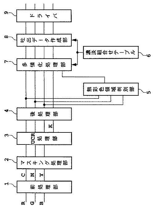
図1は、本発明の記録装置の画像処理部のブロック図である。記録装置の画像処理部は、前処理部1と、マスキング処理部2と、UCR処理部3と、後処理部4と、無彩色領域判別部5と、インクの種類や濃度の組合せを格納した濃淡組合せテーブル6と、多値化処理部7と、吐出データ作成部8と、ドライバ9とからなる。
【0054】
画像処理部に画像データがRGB信号で入力されると、前処理部1でモニタのγ特性を考慮した入力γ補正や、入力信号を人間の知覚輝度に合わせるLOG変換処理等が行われる。また、RGBからCMYへの変換も行われる。このように前処理部1で処理された画像データは、次にマスキング処理部2にて、各色での不正吸収等の補正が行われる。次にUCR処理部3で下色除去が行われる。この下色除去(Under Color Removal)の程度は特に限定されるものではなく、また、入力レベルによりその程度を変化させても良い。なお、使用インク量の低減という観点から高い割合でUCRを行う事が望ましい。本実施例に於いてはCMY各成分の最小値を完全にKに置き換えるUCR処理を行う。これら一連の処理が終わった後、後処理部4において実際に記録した時のドットゲイン量等を考慮し、適宣出力γ補正等が行われる。
【0055】
次に上述の画像処理とは別に無彩色領域判別部5で入力された画像データの無彩色領域が決定される。本実施例に於いては入力されたRGB信号を直接利用して行う。判別の際の評価式を(6)に示す。
【0056】
【数6】
MAX(R、G、B)−MIN(R、G、B)≦10・・・(6)
この評価式を満たす領域を無彩色領域とする。このようにして、有彩色領域と無彩色領域とに分けるデータが多値化処理部7に送られる。
【0057】
なお、ここでの10という値は、入力画像がカラー超音波医療画像である事、使用するインクがKに対しては6種類の濃淡インク、C、M各色に対しては2種類の濃淡インク、Yに対しては1種類のインクを使用して、かつ、1画素当たりのインク吐出数の制限が5程度で画像を出力する事を考慮して決定した。また、この大きさは、RGBの取りうる値0〜255に対して約4%にあたる。
【0058】
図2〜図4に示す濃淡組合せテーブル6には、使用するインクや記録した際の濃度情報等が格納されていて、本実施例に於いては、以下に示すようなCMY各色の濃淡インクの使用組合せとその濃度情報、及び、無彩色領域と有彩色領域での黒に対する濃淡インクの使用組合せとその濃度情報が含まれる。CMYに対しては合計5種類、黒系色6種類であり、濃淡インクは濃度の高い方から順に1,2,3・・・と添え字で示す。これらのインクの染料濃度比率を表1に示す。なお、インクは、染料及び溶媒からなり、溶媒には、界面活性剤、保湿材、等の各種添加剤が含まれている。これら添加剤は、ヘッドからの吐出特性、受像紙上での吸収特性とを制御するものである。
【0059】
【表1】
これらのインクを用いて、C、M、Yに対しては1画素を最大2ドットで形成し、黒系色に対しては無彩色領域に於いては1画素を最大4ドットで形成し、また、有彩色領域に於いては原則として1画素を1ドットで形成するとする。このようなドット数の制限に基づいて処理した結果を図2に示す。図中の数字は、1つの画素に吐出するインクドットの数を示し、0は、そのインクを吐出しないことを示している。
【0061】
また、濃度レベルの欄は、8ビット入力画像信号(0〜255:0が黒)に対応させた値を示している。すなわち、C、Mに関しては5値の多値化処理を行い、Yに関しては3値の多値化処理、また、Kに関しては、無彩色領域で43値の多値化処理、有彩色領域で9値の多値化処理を行う事となる。
【0062】
上記データをもとに、多値化処理部7において誤差拡散処理が行われる。黒系色に関しては、無彩色領域判定部5での結果を用いて、処理が行われる。このとき、無彩色領域では図3の濃度レベル(d1[0]〜d1[42])および多値化のしきい値(th[1]〜th[42])を参照して43値の多値化処理をし、また、有彩色領域では図4の濃度レベル(d1[0]〜d1[8])および多値化のしきい値(th[1]〜th[8])を参照して9値の多値化処理を行う。
【0063】
例えば、無彩色領域で入力値が濃度レベル10であった場合、図3より、
【0064】
【数7】
th[1]≦10<th[2]
となるので、X=1が求められる。したがって、この画素の濃度レベルは、
【0065】
【数8】
dl[1]=14
と決定され、誤差は4(=14−10)と求められる。
【0066】
このようにして求めた誤差を従来から知られている誤差拡散法により周辺の画素に分散するものとする。
【0067】
このように多値化処理された画像データは、吐出データ作成部8に於いて、再び濃淡組合せテーブル6のデータと参照させて、各種インクの吐出データになる。すなわち、所定の画素に対してどのインクを何ドット吐出するかが決定される。記録パス数等のパラメータを設定することにより、ドライバ9で吐出口毎の吐出タイミングや記録媒体のフィード量等の各種駆動条件が決定され、実際に画像が出力される事となる。
【0068】
なおここでは、600dpi相当のインクジェットヘッド(256ノズル×3のマルチヘッド:吐出量9pl)を4個使用して出力した。その結果、カラー部分、モノクロ部分とも良好な階調画像を得ることができた。
【0069】
(比較例1)
RGB各8bitのカラー超音波医療画像を、実施例1の場合と同様に黒系色に対しては6種類の濃淡インクを使用し、また、C、M各色に対しては2種類の濃淡インク、Yに対しては1種類のインクを使用して、かつ、実施例1の場合と同じ記録媒体に出力した。ただし、実施例1の場合との相違点は、図1における無彩色領域判別部5での評価の基準を(6)式とした。
【0070】
【数9】
MAX(R、G、B)−MIN(R、G、B)≦50・・・(6)
なお、この50という値は、RGBの取りうる値に対して、約20%にあたる。その結果、無彩色領域はこの画像全体の中で約86%を占める事となった。ちなみに、実施例1の場合では、約79%であった。
【0071】
このようにして無彩色領域を判別した後、実施例1と同様に、多値化処理等を行い、カラー画像を出力した。その結果、画像の一部でインク溢れが生じ、好ましくなかった。
【0072】
(比較例2)
RGB各8bitのカラー超音波医療画像を、実施例1の場合と同様に出力した。但し、実施例1の場合との相違点は、図1における無彩色領域判別部5での評価の基準を(7)式とした。
【0073】
【数10】
MAX(R、G、B)−MIN(R、G、B)≦2・・・(7)
なお、この2という値は、RGBの取りうる値に対して、約0.8%にあたる。その結果、無彩色領域はこの画像全体の中で僅かに約7%を占める事となった。
【0074】
このようにして無彩色領域を判別した後、実施例1と同様に、多値化処理等を行い、カラー画像を出力した。その結果、インク溢れは生じなかったものの、階調性が重視される無彩色領域(グレー部分)に於いては、インクドットが濃度の違いとして認識される部分もあった。
【0075】
(実施例2)
本実施例では、無彩色領域の判別方法として、C,M,Y信号を利用する方法を説明する。
【0076】
RGB各8bitのカラー超音波医療画像を、実施例1の場合と同様に黒系色に対しては6種類の濃淡インクを使用し、また、C、M各色に対しては2種類の濃淡インク、Yに対しては1種類のインクを使用して、かつ、実施例1の場合と同じ記録媒体に出力した。本実施例における画像処理のブロック図を、図5に示す。
【0077】
本実施例と実施例1との相違点は、無彩色領域判別方法であり、ここでは図5に示すようにマスキングやUCR、出力ガンマ補正等の処理を行った後のCMY信号から無彩色領域を判定するものとする。また、無彩色領域判別部5における評価の基準を(8)式とした。
【0078】
【数11】
MAX(C、M、Y)−MIN(C、M、Y)≦15・・・(8)
なお、ここでの15という値は、CMYの取りうる値0〜255に対して約6%にあたる。
【0079】
このようにして無彩色領域を判別した後、実施例1と同様に、多値化処理等を行い、600dpi相当のインクジェットヘッド(256ノズル×3のマルチヘッド:吐出量8.5pl)を4個使用して出力した。その結果、カラー部分、モノクロ部分とも良好な階調画像を得ることができた。
【0080】
(実施例3)
本実施例では、入力信号がビデオ信号のときを説明する。
【0081】
ビデオ信号で入力されるカラー超音波医療画像を、黒系色に対しては3種類の濃淡インクを使用し、また、CMY各色に対しては1種類のインクを使用して、反射媒体に出力した。ここで使用したインク、記録媒体における1画素当たりのインク吐出数の制限は4程度である。
【0082】
本実施例における画像処理のブロック図を、図6に示す。入力されたビデオ信号は、無彩色領域判別部5に入力され、そこで無彩色領域か否かの判別が行われる。ここでは、評価の基準を(9)式とした。
【0083】
【数12】
((R−Y′)2 +(B−Y′)2 )1/2 ≦6・・・(9)
このようにして無彩色領域を判別するとともに、入力した画像信号はRGB変換部10によりRGB信号に変換した後、実施例1の場合と同様にγ補正、マスキング、UCR等の処理が行われ、多値化処理部7に至る。
【0084】
濃淡組合せテーブル6には、CMY各色の濃淡インクの使用組合せとその濃度情報、及び、無彩色領域と有彩色領域での黒に対する濃淡インクの使用組合せとその濃度情報が含まれる。C、M、Y、Kそれぞれのインクの染料濃度比率を表2に示す。
【0085】
【表2】
これらのインクを用いて、CMYに対しては1画素を最大2ドットで形成し、Kに対しては無彩色領域に於いては1画素を最大3ドットで形成し、また、有彩色領域に於いては原則として1画素を1ドットで形成する。この結果を、図7、図8、図9に示す。すなわち、CMYに関しては3値の多値化処理を行い、また、Kに関しては、無彩色領域で18値の多値化処理、有彩色領域で6値の多値化処理を行う事となる。
【0087】
実施例1と同様に、多値化処理等を行い、600dpi相当のインクジェットヘッド(256ノズル×3のマルチヘッド:吐出量12pl)を2個使用して出力した。その結果、カラー部分、モノクロ部分とも良好な階調画像を得ることができた。
【0088】
(実施例4)
RGB各8bitのカラー超音波医療画像を、実施例1の場合と同様に黒系色に対しては6種類の濃淡インクを使用し、また、C、M各色に対しては2種類の濃淡インク、Yに対しては1種類のインクを使用して、かつ、実施例1の場合と同じ記録媒体に出力するものとする。
【0089】
本実施例における画像処理のブロック図を、図10に示す。入力されたRGB信号は、Lab変換部11によりRGBからL* a* b* 信号に変換され、無彩色領域判別部5に入力される。無彩色領域か否かの判別は、(10)式で行った。
【0090】
【数13】
((a* )2 +(b* )2 )1/2 ≦8・・・(10)
このようにして無彩色領域を判別するとともに、入力した画像信号は実施例1の場合と同様にγ補正、マスキング、UCR等の処理が行われ、多値化処理部7に至る。多値化処理部7に於いては、上記無彩色領域か否かの判別結果を照らし合わせながら、CMに関しては5値の多値化処理、Yに関しては3値の多値化処理、また、Kに関しては、無彩色領域で43値の多値化処理、有彩色領域で9値の多値化処理を行う事となる。
【0091】
この結果をもとに、600dpi相当のインクジェットヘッド(256ノズル×3のマルチヘッド:吐出量9pl)を4個使用してカラー画像を出力した。その結果、カラー部分、モノクロ部分とも良好な階調画像を得ることができた。
【0092】
なお、実施例はいずれもインクジェット方式の記録装置について述べたものであるが、本発明の記録装置および記録方法を用いることによって、コックリングやインク溢れなどの発生を抑制するだけでなく、無彩色領域、有彩色領域の判別により黒系色の付与量を調節することで、画質を向上させることができるので、本発明はインクジェット方式に限定せず、熱転写方式や感熱方式など他の方式の記録装置に適用してもよいことは勿論である。
【0093】
【発明の効果】
以上説明したように、本発明の記録装置および記録方法を用いて、入力した画像データを無彩色領域と有彩色領域とに判別し、無彩色領域では黒系色の打ち込み可能なドット数を多くし、有彩色領域では逆に黒系色の打ち込み可能なドット数を少なくすることにより、無彩色領域では、より多くの階調数を表現できるようになり、有彩色領域では、黒系色の上にさらにC,M,Yのカラーインクを打ち込むことが可能となる。したがって、黒の階調表現を十分満たした上で、さらに色再現性も十分に満足しうるカラー画像を得る事ができる。すなわち、カラー超音波医療画像など、黒の階調性とカラー化との両方に対して高品位の画像を要求するものであっても、十分再生することが可能となる。
【図面の簡単な説明】
【図1】本発明の実施例1における画像処理のブロック図である。
【図2】実施例1におけるCMYの濃淡組合せテーブル図である。
【図3】実施例1における無彩色領域でのKの濃淡組合せテーブル図である。
【図4】実施例1における有彩色領域でのKの濃淡組合せテーブル図である。
【図5】本発明の実施例2における画像処理のブロック図である。
【図6】本発明の実施例3における画像処理のブロック図である。
【図7】実施例3におけるCMYの濃淡組合せテーブル図である。
【図8】実施例3における無彩色領域でのKの濃淡組合せテーブル図である。
【図9】実施例3における有彩色領域でのKの濃淡組合せテーブル図である。
【図10】本発明の実施例4における画像処理のブロック図である。
【符号の説明】
1 前処理部
2 マスキング処理部
3 UCR処理部
4 後処理部
5 無彩色領域判別部(領域判定手段)
6 濃淡組合せテーブル(濃淡組合せ手段)
7 多値化処理部
8 吐出データ作成部
9 ドライバ
10 RGB変換部
11 Lab変換部[0001]
BACKGROUND OF THE INVENTION
The present invention relates to a recording apparatus and a recording method for forming an ink dot by ejecting ink and recording an image using the ink dot. More specifically, the present invention relates to a plurality of inks having different densities, particularly for black. The present invention relates to a recording apparatus and a recording method for recording a color image.
[0002]
[Prior art]
In recent years, with the spread of information processing equipment such as copying machines, word processors, computers, and communication equipment, digital images using an ink jet recording head as one of the image forming and recording devices of those equipment. The one that records is rapidly spreading. In addition, with the increase in quality and color of visual information in the information equipment and communication equipment, there is an increasing demand for higher image quality and color in recording apparatuses.
[0003]
As a configuration of such a recording apparatus aiming at high image quality of a color image, a recording head (hereinafter also referred to as a multi-head) in which a plurality of recording elements are integrated and arranged corresponding to pixel miniaturization, for example, an ink jet system In this case, it is known to use a head in which a plurality of ink discharge ports and liquid paths are integrated at a high density. In order to record a color image, such a multi-head is provided corresponding to, for example, cyan, magenta, yellow, and black inks.
[0004]
However, there is a certain limit to the high-density integration of discharge ports and liquid channels that is possible with the current technology. Therefore, there is a certain limit to pixel miniaturization. In such a case, the dots forming each pixel also have a certain size corresponding thereto, and therefore, in a low density portion such as a highlight portion of the image, a graininess may be exhibited, and the image quality of the image may be reduced. May cause problems.
[0005]
On the other hand, instead of increasing the density of the discharge ports and the liquid channels, that is, instead of reducing the size of one pixel, the ink discharge amount is reduced by reducing the discharge port itself, etc. A so-called multi-drop method is known in which dots are formed by ejecting ink droplets to the same pixel a plurality of times according to the density of an image to be recorded. In the multi-drop method, since the dot diameter recorded on the recording paper can be made relatively small, the graininess in a low density portion such as a highlight portion can be improved. However, if the ink droplets to be ejected are too small, there is a tendency for ejection to become unstable, so there is a certain limit to reducing the size of the ink droplets. As a result, there is a limit to improving the image quality. In this method, the higher the density is, the more ink droplets are ejected to one pixel. Therefore, the recording operation takes time and the recording speed is reduced. As a result, there is a contradictory relationship between high image quality and recording speed.
[0006]
In addition, as another technique for improving the image quality without increasing the discharge port integration density, a density recording system using inks of similar colors with different ink densities is known. In this method, highlight portions and the like are recorded with relatively low-density ink (hereinafter also referred to as “light ink”) to make the graininess inconspicuous, and high-density portions are relatively high-density ink ( (Hereinafter also referred to as “dark ink”). Therefore, a high density portion can be formed without increasing the number of inks ejected to one pixel, that is, the number of ejections as in the multi-drop method, and a decrease in recording speed can be suppressed.
[0007]
However, even with the above method using dark and light inks, there are cases where, for example, medical images, particularly monochrome images such as X-ray images, are not suitable. In other words, such an image is a monochrome image but requires a relatively strict gradation. A transparent film or the like is used as a recording medium for recording an X-ray image or the like. When an image is formed and output by such a recording device on such a transmissive recording medium, the absolute amount of light is larger in the transmissive image than in the reflected image, that is, the dynamic range to be visually recognized is widened. The number of recognizable gradations will increase. Therefore, the visual resolution with respect to the density is increased, and as a result, even when the dark and light ink is used, the density difference for each pixel is recognized and the image may be rough. In order to improve this, it is considered to increase the number of gradations for each pixel. However, in order to further increase the gradation for each pixel, the above method increases the types of light and dark inks and A large number of multiheads are required. That is, the cost increases significantly.
[0008]
Therefore, in the Japanese Patent Application No. 9-323435, the inventors of the present application print, for example, about 4 drops of similar colors, particularly black ink, on the same pixel, and give more gradations per pixel. A method has been proposed, and as a result, more gradations can be expressed without greatly increasing the number of dark and light inks and multiheads.
[0009]
As a pseudo halftone processing method using binarization processing or multi-value processing used in the above recording method, a dither method, an error diffusion method, an average density storage method, and the like are known.
[0010]
In the dither method, data of each pixel is binarized by a threshold value for each pixel defined by a dither matrix.
[0011]
For example, as described in the document R.FLOYD & L.STEINBERG, “AN ADAPTIVE ALGORITHM FOR SPETIAL GRAY SCALE”, SID 75 DIGEST, PP36 to 37, the error diffusion method binarizes the image data of the pixel of interest (the darkest level). Or the difference (error) between the binarized level and the value before binarization is distributed to the surrounding pixels and added.
[0012]
In addition, the average density preservation method is, for example, binary data already binarized in the vicinity of the target pixel, or the target pixel binarized to black or white, as described in, for example, Japanese Patent Application Laid-Open No. 2-210962 A threshold value is obtained based on the data including the image, and the target image data is binarized by the threshold value.
[0013]
Furthermore, multi-value processing can be performed by slightly modifying these various binarization methods.
[0014]
[Problems to be solved by the invention]
However, the method of stacking inks having different densities has the following problems.
[0015]
In other words, there is a limit to the allowable amount of ink in the recording medium, and if ink exceeding the allowable amount is ejected to the same pixel, the ink cannot be absorbed, causing “ink overflow” or absorbed ink. “Cockling” may occur due to the water content.
[0016]
For example, when outputting a medical image that requires both black gradation and colorization, such as a color ultrasonic image, black-based light and dark ink is used with emphasis on black gradation. If the recording medium is ejected to the vicinity of the allowable amount of ink absorption, there is no longer the ability to absorb cyan, magenta and yellow inks. Problems may occur.
[0017]
On the contrary, if the degree of freedom of overprinting with black and light inks is reduced so that colorization is emphasized and cyan, magenta, and yellow inks can be sufficiently absorbed, sufficient black levels are obtained. There may be a problem that the tonality cannot be ensured.
[0018]
The present invention has been made to solve the above-described problems, and an object of the present invention is to provide a recording apparatus capable of suppressing the occurrence of problems such as ink overflow even when forming a color image with sufficiently maintained black gradation. And a recording method.
[0019]
[Means for Solving the Problems]
The recording apparatus of the present invention is a recording apparatus that records an image on a recording medium using a plurality of types of black inks having different densities and inks of other colors. An area determination unit that determines whether the color to be represented belongs to an achromatic color area or a chromatic color area, and is assigned to one pixel according to the image data for each area determined by the area determination unit Determining means for determining the type and applied amount of ink, wherein the determining means is the number of gradations that can be expressed by the black color ink And amount of black color ink applied The determination is performed so that the number is larger in the achromatic color region than in the chromatic color region.
[0020]
The region determination means may be an achromatic region as long as the difference between the maximum and minimum RGB signal values for each pixel of the image data to be reproduced is equal to or less than a predetermined value.
[0021]
The area determination means may be an achromatic area as long as the difference between the maximum value and the minimum value of the CMY signals for each pixel of the image data to be reproduced is equal to or less than a predetermined value.
[0022]
Further, the area determination means calculates ((R−Y ′)) from the luminance signal Y ′, color difference signal RY ′, and color difference signal BY ′ for each pixel of the image data to be reproduced. 2 + (B−Y ′) 2 ) 1/2 If this value is equal to or less than a predetermined value, an achromatic region may be used.
[0023]
The recording method of the present invention is a recording method using a recording apparatus that forms an image with a plurality of types of black inks having different densities and inks of other colors. A region determination unit that determines whether the region belongs to any one of the chromatic color regions, and for each region determined by the region determination unit, the type and amount of ink applied to one pixel according to the image data A light / dark combination means for determining is provided.
[0024]
By using the recording apparatus and the recording method of the present invention, the image data to be recorded is divided into an achromatic region and a chromatic region, and the chromatic region discharges black ink droplets as compared to the achromatic region. By reducing the limit number, it is possible to prevent ink leakage and cockling even when ink droplets of other colors such as C, M, and Y are stacked and ejected.
[0025]
DETAILED DESCRIPTION OF THE INVENTION
An embodiment of a recording apparatus and a recording method of the present invention will be described below with reference to the drawings.
[0026]
A recording apparatus according to an embodiment of the present invention is provided with a plurality of dark and light inks for black-colored colors and inks necessary for color recording such as cyan, magenta, and yellow.
[0027]
First, as described in the problem, there is a limit to the allowable amount of ink in the recording medium. Therefore, there is a limit to the number of ink droplets that can be ejected to one pixel. Therefore, the relationship between the allowable amount of ink that can be absorbed by the area of one pixel and the number of ink droplets will be described.
[0028]
When the volume of the ink droplet to be ejected is V and the diameter of the dot formed as a result is r, the relationship of formula (1) is almost established.
[0029]
[Expression 1]
V∝r 2 ... (1)
Further, when the dot diameter when forming an image is r, the recording density at that time, that is, the length x of one side of one pixel, which is the minimum unit of the image, is approximately the value shown by the expression (2). It is.
[0030]
[Expression 2]
x = 2 1/2 Xr (2)
On the other hand, the amount of ink W that can be absorbed within the area of one pixel is considered to be proportional to the thickness d of the ink receiving layer of the recording medium on which dots are formed.
[0031]
[Equation 3]
W∝x 2 Xd (3)
Therefore, the ink droplet limit number t that can be discharged to one pixel is
[0032]
[Expression 4]
t = W / V∝2d (4)
Therefore, if the relationship between the dot diameter and the recording density (2) is maintained, the ink droplet limit number t that can be ejected to one pixel becomes a substantially constant value regardless of the recording density or the like. In other words, the ink droplet limit number t is an amount that depends on the characteristics of the recording medium, the characteristics of the ink, and the like, and is generally 3 to 8, particularly about 4 to 6, for one pixel.
[0033]
In this embodiment, image formation is performed based on the above-described ink droplet limit number. However, the ink droplet limit number varies depending on the characteristics of the recording medium and the ink, and the present invention falls within this range. It is not limited.
[0034]
Next, the density ink discharge combinations and the number of multi-values when expressing gradation by discharging various density inks are described below.
[0035]
For example, when n types of dark and light inks are used, the combination of the numbers of discharges formed with the respective dark and light inks (light and dark combinations) is selected from the n types of dark and light inks when one pixel is formed by only one dot. Select only one type n C 1 = When there are n combinations, and when one pixel is formed with two dots, two types are selected from n types of dark and light inks, and each one dot is formed. n C 2 = N (n-1) / 2 types, and when selecting one of n types of dark and light inks and forming two dots of that ink n C 1 There are n combinations. Furthermore, when one pixel is formed with three dots, three types are selected from n types of light and dark inks, and each one dot is formed. n C Three = N (n-1) (n-2) / 6 types, and one type is selected from n types of dark and light inks, and two more dots are formed, and n-1 types of light and dark inks When one type is selected from the inside and one more dot is formed n C 1 ・ n-1 C 1 = (N-1) ways, and when selecting one kind from n kinds of light and dark inks and forming 3 dots of that ink n C 1 There are n combinations. That is, as the number of dots that can be formed in one pixel increases, and as the number of types of dark and light ink to be used increases, the number of dark and light combination increases. In addition, there are many dark and light combinations having almost the same density depending on the density ratio of the dark and light inks to be used.
[0036]
However, as described above, since there is a limit to the number of dots that can be applied to one pixel, there is a limit to the combination of shades.
[0037]
Therefore, in the present invention, the image data to be reproduced is divided into an achromatic color region and a chromatic color region. In the achromatic region, the number of black-colored dots that can be printed in one pixel is increased to provide a range of selection of black / dark combinations. On the other hand, in the chromatic color area, by reducing the number of black-colored dots that can be applied to one pixel as compared to the achromatic color area, it is possible to solve problems such as ink overflow while sufficiently supporting chromatic color recording. Can do.
[0038]
For example, in the achromatic color region, the maximum number of black-colored dots to be shot per pixel is p dots, and in the chromatic color region, except for the vicinity of the maximum density, the maximum is q dots (t ≧ p> q) in principle. A combination of shades is selected within the range of the number of dots. Therefore, the multivalued number m in the achromatic region at that time k Is the multivalued number m in the chromatic color region. c More than (m k > M c ).
[0039]
Furthermore, although it is related to the resolution of the output image, the multivalued number m k It is effective that the dot is at least 10 or more from the viewpoint of making the dots inconspicuous.
[0040]
Here, the black color is mainly used as the ink forming the achromatic color region, and therefore, the degree of chromatic color C, M, and Y color inks that are superimposed is small. Therefore, in the achromatic region, the number of black ink discharges (number of dots) per pixel is increased so that more gradations can be expressed. In other words, gradation-oriented image output is performed. On the other hand, the ink that forms the chromatic color region includes not only black colors but also C, M, and Y color inks. Therefore, there is a margin for printing color inks on top of black inks. I have to let it go. Thus, by reducing the number of black color ink ejections per pixel as compared to the achromatic region, the number of gradations can be reduced, but the amount of black color ink applied per pixel can be suppressed. Accordingly, it is possible to use the C, M, and Y color inks more sufficiently on the dots formed with the black color, and to perform image output with an emphasis on color reproducibility. In this way, by dividing one image data into an achromatic color region and a chromatic color region, and changing the number of dots that can be imprinted with black color ink depending on the region, a color that can sufficiently satisfy the black gradation property. Images can be played back.
[0041]
Next, a method for determining an achromatic region will be described. In the present embodiment, as a method for determining an achromatic color region, for example, a method using an RGB signal, a method using two color difference signals of a color video signal, and a value of a color coordinate when converted to a uniform color space coordinate However, the present invention is not limited to these methods, and other methods may be used.
[0042]
The above-described methods will be described below.
[0043]
As a specific method for using RGB 8-bit signals, a difference between RGB values, specifically, a value of MAX (R, G, B) −MIN (R, G, B) is set in advance. If the value is within the range, the achromatic region is set, and if the value is exceeded, the chromatic region is set. It is assumed that a suitable value is set as the set value in accordance with the type and image characteristics of the input image and further in accordance with the ink density of each color to be used. In the present embodiment, the determination is made based on whether the number is within 10. In addition, although the method using the RGB signal itself does not strictly reflect the information regarding the color, it can be evaluated for a certain color, and the determination circuit of the achromatic region is simplified. It is also effective in terms of points.
[0044]
As a specific method of converting the input signal into C, M, Y or C, M, Y, K colors and using the three values C, M, Y, the RGB signal is used. Similarly, if the difference between the values, that is, the value of MAX (C, M, Y) −MIN (C, M, Y) is within an arbitrary set value, the region is an achromatic region. Suppose that it is a chromatic color region. The set value is not particularly limited, and is set appropriately according to the type and image characteristics of the input image, and further according to the ink density of each color to be used. In the present embodiment, the determination is made based on whether it is within 10 or less.
[0045]
In the above two methods, the threshold value for evaluating the set value, that is, the value of MAX (RorC, GorM, BorY) −MIN (RorC, GorM, BorY) is particularly limited as described above. Although not intended, as one guideline, it is desirable that the value be 1% or more and 10% or less of RGB or CMY. If this value is too large, the range of the achromatic area will be expanded, and ink overflow will occur by printing color ink on that area, and if it is too small, the achromatic area will not be recognized depending on the image, and the image will emphasize gradation. This is because it becomes impossible to output.
[0046]
Next, a method of using a color video signal is performed as follows. Two color difference signals RY ′ and BY ′ are obtained and from the two color difference signals ((R−Y ′) 2 + (B−Y ′) 2 ) 1/2 If this value is within an arbitrary set value, an achromatic color region is determined, and if it is equal to or greater than the set value, a chromatic color region is determined. In the case where the input image signal is an RGB signal, a conversion formula that is generally used may be used. For example, the following formula (5) may be used. In addition, values obtained by performing various corrections can be used.
[0047]
[Equation 5]
For example, the CIELAB color space or the CIELV color space is used as a method of using the value of the color coordinate when converted to the uniform color space coordinate. In the uniform color space, all colors are shown in three-dimensional orthogonal coordinates, and a * , B * And u * , V * Indicates hue and saturation as color coordinates. In addition, since the visual color difference and the numerical difference are almost the same, it is effective for determining whether or not the region is an achromatic region. Specifically, (a * ) 2 + (B * ) 2 Or (u * ) 2 + (V * ) 2 Is within an arbitrary set value, an achromatic region, and if it is above, a chromatic region.
[0049]
The multi-value processing used in the present invention is not particularly limited, but in the black multi-value processing, the number of multi-values in the achromatic region and the chromatic region in one image is the same. Therefore, an error diffusion method that can change the number of multi-values in the middle of processing is preferable. It is possible to perform multi-value processing independently in two regions using a multi-value dither method or the like, but care must be taken because image deterioration is likely to occur at the boundary between these binary regions.
[0050]
The ink jet recording method used in the present invention can be applied to any of the conventionally known ink jet recording systems in which recording is performed by ejecting ink droplets from nozzles using various driving principles. As a representative example, the method described in Japanese Patent Application Laid-Open No. 54-59936 causes a sudden volume change of the ink subjected to the action of thermal energy, and the ink is ejected from the nozzle by the action force due to this state change. An ink jet method can be given.
[0051]
【Example】
Hereinafter, embodiments of the present invention will be described in detail with reference to the drawings.
[0052]
Example 1
6 colors of light and dark ink are used for black colors, 2 kinds of light and dark inks are used for cyan, magenta and each color, and 1 kind of ink is used for yellow. A recording apparatus for forming a color ultrasonic medical image will be described. A case where the limit of the number of ink ejections per pixel (the number of dots) is about 5 will be described as an example. The recording medium used here is a glossy film having an ink receiving layer.
[0053]
FIG. 1 is a block diagram of an image processing unit of the recording apparatus of the present invention. The image processing unit of the recording apparatus stores a
[0054]
When image data is input to the image processing unit as RGB signals, the
[0055]
Next, in addition to the above-described image processing, the achromatic color area of the image data input by the achromatic color
[0056]
[Formula 6]
MAX (R, G, B) −MIN (R, G, B) ≦ 10 (6)
A region satisfying this evaluation formula is defined as an achromatic region. In this way, the data divided into the chromatic color region and the achromatic color region is sent to the
[0057]
The value of 10 here means that the input image is a color ultrasonic medical image, the ink used is K types of light and dark inks for K, and the C and M colors are two types of light and dark inks. , Y are determined in consideration of using one kind of ink and outputting an image with a limit of about 5 ink ejections per pixel. This size corresponds to about 4% of the
[0058]
The density combination table 6 shown in FIGS. 2 to 4 stores ink to be used, density information at the time of recording, and the like. In this embodiment, the density inks of the CMY colors shown below are stored. The usage combination and its density information, and the usage combination and density information of dark and light inks for black in the achromatic and chromatic areas are included. For CMY, there are a total of 5 types and 6 types of black color, and dark and light inks are indicated by
[0059]
[Table 1]
Using these inks, one pixel is formed with a maximum of 2 dots for C, M, and Y, and one pixel is formed with a maximum of 4 dots in an achromatic region for a black color, In a chromatic color region, one pixel is formed by one dot in principle. FIG. 2 shows the result of processing based on the limitation on the number of dots. The numbers in the figure indicate the number of ink dots ejected to one pixel, and 0 indicates that the ink is not ejected.
[0061]
Further, the density level column shows values corresponding to 8-bit input image signals (0 to 255: 0 is black). That is, quinary multi-value processing is performed for C and M, ternary multi-value processing is performed for Y, and 43-value multi-value processing is performed in the achromatic region for K and chromatic color region. A 9-value multi-value processing is performed.
[0062]
Based on the above data, an error diffusion process is performed in the
[0063]
For example, when the input value is the
[0064]
[Expression 7]
th [1] ≦ 10 <th [2]
Therefore, X = 1 is obtained. Therefore, the density level of this pixel is
[0065]
[Equation 8]
dl [1] = 14
And the error is calculated as 4 (= 14−10).
[0066]
It is assumed that the error thus obtained is distributed to surrounding pixels by a conventionally known error diffusion method.
[0067]
The image data subjected to the multi-value processing in this manner is referred to again with the data of the density combination table 6 in the ejection
[0068]
Here, the output was performed using four inkjet heads equivalent to 600 dpi (256 nozzles × 3 multi-heads:
[0069]
(Comparative Example 1)
As in the case of the first embodiment, six types of light and dark inks are used for black-colored colors, and two types of light and dark inks are used for C and M colors. For Y and Y, one type of ink was used and output to the same recording medium as in Example 1. However, the difference from the case of Example 1 is that the evaluation standard in the achromatic color
[0070]
[Equation 9]
MAX (R, G, B) −MIN (R, G, B) ≦ 50 (6)
Note that this value of 50 corresponds to about 20% of the possible RGB values. As a result, the achromatic region accounted for about 86% of the entire image. Incidentally, in the case of Example 1, it was about 79%.
[0071]
After determining the achromatic color region in this way, a multi-value processing or the like was performed as in Example 1 to output a color image. As a result, ink overflow occurred in a part of the image, which was not preferable.
[0072]
(Comparative Example 2)
An RGB 8-bit color ultrasonic medical image was output in the same manner as in Example 1. However, the difference from the case of the first embodiment is that the evaluation standard in the achromatic
[0073]
[Expression 10]
MAX (R, G, B) −MIN (R, G, B) ≦ 2 (7)
The value of 2 corresponds to about 0.8% of the possible RGB values. As a result, the achromatic region accounted for only about 7% of the entire image.
[0074]
After determining the achromatic color region in this way, a multi-value processing or the like was performed as in Example 1 to output a color image. As a result, although ink overflow did not occur, in the achromatic region (gray portion) where gradation is important, there was a portion where ink dots were recognized as a difference in density.
[0075]
(Example 2)
In the present embodiment, a method using C, M, and Y signals will be described as a method for determining an achromatic region.
[0076]
As in the case of the first embodiment, six types of light and dark inks are used for black-colored colors, and two types of light and dark inks are used for C and M colors. For Y and Y, one type of ink was used and output to the same recording medium as in Example 1. A block diagram of image processing in this embodiment is shown in FIG.
[0077]
The difference between the present embodiment and the first embodiment is an achromatic color region discrimination method, and here, as shown in FIG. 5, the achromatic color region is obtained from the CMY signal after performing processing such as masking, UCR, and output gamma correction. Shall be determined. In addition, the evaluation standard in the achromatic color
[0078]
[Expression 11]
MAX (C, M, Y) −MIN (C, M, Y) ≦ 15 (8)
Here, the value of 15 corresponds to about 6% of the
[0079]
After determining the achromatic region in this way, multi-value processing is performed in the same manner as in the first embodiment, and four inkjet heads equivalent to 600 dpi (256 nozzles × 3 multi-head: discharge amount 8.5 pl) are provided. Output using. As a result, good gradation images could be obtained for both the color part and the monochrome part.
[0080]
Example 3
In this embodiment, the case where the input signal is a video signal will be described.
[0081]
Color ultrasound medical images input as video signals are output to a reflective medium using three types of dark and light inks for black colors and one type of ink for CMY colors did. The limit of the number of ink ejections per pixel in the ink and recording medium used here is about 4.
[0082]
A block diagram of image processing in this embodiment is shown in FIG. The input video signal is input to the achromatic color
[0083]
[Expression 12]
((R-Y ') 2 + (B−Y ′) 2 ) 1/2 ≦ 6 (9)
In this way, the achromatic region is discriminated, and the input image signal is converted into an RGB signal by the
[0084]
The light / dark combination table 6 includes the light and dark ink use combinations of CMY colors and their density information, and the light and dark ink use combinations and density information for black in the achromatic and chromatic areas. Table 2 shows the dye concentration ratio of each of the C, M, Y, and K inks.
[0085]
[Table 2]
Using these inks, one pixel is formed with a maximum of 2 dots for CMY, one pixel is formed with a maximum of 3 dots for an achromatic region for K, and In principle, one pixel is formed by one dot. The results are shown in FIG. 7, FIG. 8, and FIG. That is, for CMY, ternary multi-value processing is performed, and for K, 18-value multi-value processing is performed in the achromatic color region and 6-value multi-value processing is performed in the chromatic color region.
[0087]
In the same manner as in Example 1, multi-value processing and the like were performed, and output was performed using two inkjet heads equivalent to 600 dpi (256 nozzles × 3 multi-head:
[0088]
(Example 4)
As in the case of the first embodiment, six types of light and dark inks are used for black color colors, and two types of light and dark inks are used for C and M colors. For Y and Y, one type of ink is used and output to the same recording medium as in the first embodiment.
[0089]
A block diagram of image processing in this embodiment is shown in FIG. The input RGB signal is converted from RGB to L by the
[0090]
[Formula 13]
((A * ) 2 + (B * ) 2 ) 1/2 ≦ 8 (10)
In this way, the achromatic region is determined, and the input image signal is subjected to processing such as γ correction, masking, UCR, and the like in the same manner as in the first embodiment, and reaches the
[0091]
Based on this result, a color image was output using four inkjet heads equivalent to 600 dpi (256 nozzles × 3 multi-head:
[0092]
In addition, although all the embodiments described the ink jet recording apparatus, the use of the recording apparatus and the recording method of the present invention not only suppresses the occurrence of cockling and ink overflow, but also achromatic colors. Since the image quality can be improved by adjusting the amount of black-colored color by discriminating between areas and chromatic areas, the present invention is not limited to the ink jet system, and other types of recording such as a thermal transfer system and a thermal system are used. Of course, it may be applied to the apparatus.
[0093]
【The invention's effect】
As described above, by using the recording apparatus and the recording method of the present invention, the input image data is discriminated into an achromatic color area and a chromatic color area, and in the achromatic color area, the number of dots that can be printed with a black color is increased. On the other hand, by reducing the number of dots that can be printed with black color in the chromatic color area, more gradations can be expressed in the achromatic color area, and in black areas in the chromatic color area. Further, it becomes possible to print color inks of C, M, and Y on the top. Therefore, it is possible to obtain a color image that sufficiently satisfies the black gradation expression and further sufficiently satisfies the color reproducibility. That is, even a color ultrasonic medical image or the like that requires a high-quality image for both black gradation and colorization can be sufficiently reproduced.
[Brief description of the drawings]
FIG. 1 is a block diagram of image processing in
FIG. 2 is a CMY density combination table in the first embodiment.
FIG. 3 is a K light / dark combination table in an achromatic region according to the first exemplary embodiment.
FIG. 4 is a K light / dark combination table in the chromatic color area according to the first embodiment.
FIG. 5 is a block diagram of image processing in
FIG. 6 is a block diagram of image processing in
FIG. 7 is a CMY density combination table in the third embodiment.
FIG. 8 is a K light / dark combination table in the achromatic region according to the third embodiment.
FIG. 9 is a table showing a combination of shades of K in a chromatic color area according to the third embodiment.
FIG. 10 is a block diagram of image processing in
[Explanation of symbols]
1 Pre-processing section
2 Masking processing part
3 UCR processing section
4 Post-processing section
5 Achromatic color region discriminator (region discriminating means)
6 Light / dark combination table (light / light combination means)
7 Multi-value processor
8 Discharge data creation unit
9 Driver
10 RGB converter
11 Lab converter
Claims (14)
画像データに基づき、該画像データが表す色が無彩色領域または有彩色領域のいずれに属するかを判別する領域判定手段と、
前記領域判定手段により判別された領域ごとに、当該画像データに応じて1つの画素に対して付与する前記黒系色インクの種類および付与量を決定する決定手段とを有し、
前記決定手段は、前記黒系色インクで表現可能な階調数および前記黒系色インクの付与量が前記有彩色領域よりも前記無彩色領域の方で多くなるように前記決定を行うことを特徴とする記録装置。In a recording apparatus that records an image on a recording medium using a plurality of types of black inks having different densities and other color inks,
Area determination means for determining whether a color represented by the image data belongs to an achromatic color area or a chromatic color area based on the image data;
Determining means for determining the type and amount of the black color ink to be applied to one pixel according to the image data for each area determined by the area determination means;
The determination means performs the determination so that the number of gradations that can be expressed by the black color ink and the amount of the black color ink applied are larger in the achromatic color region than in the chromatic color region. A recording apparatus.
画像データに基づき、該画像データが表す色が無彩色領域または有彩色領域のいずれに属するかを判別する領域判定工程と、
前記領域判定工程により判別された領域ごとに、当該画像データに応じて1つの画素に対して付与する前記濃度の異なる複数種類の黒系色インクの種類および付与量を決定する決定工程とを有し、
前記決定工程では、前記黒系色インクで表現可能な階調数および前記黒系色インクの付与量が前記有彩色領域よりも前記無彩色領域の方で多くなるように前記決定を行うことを特徴とする記録方法。In a recording method for recording an image on a recording medium using a plurality of types of black inks having different densities and other color inks,
An area determination step for determining whether the color represented by the image data belongs to an achromatic area or a chromatic area based on the image data;
For each region determined by the region determination step, there is a determination step for determining the types and application amounts of the plurality of types of black color inks having different densities to be applied to one pixel according to the image data. And
In the determination step, the determination is performed such that the number of gradations that can be expressed by the black color ink and the application amount of the black color ink are larger in the achromatic color region than in the chromatic color region. A characteristic recording method.
前記有彩色領域の記録に用いる前記黒系色インクの種類およびその付与量についての情報が格納された第2テーブルを参照することにより、前記有彩色領域の各画素に対して付与する前記黒系色インクの種類およびその付与量を決定することを特徴とする請求項11に記載の記録方法。The determining step refers to a first table in which information about the type of black color ink used for recording the achromatic color area and the amount of the black ink is stored, and thereby for each pixel in the achromatic color area. Determine the type of black ink to be applied and the amount of the ink,
The black system to be applied to each pixel in the chromatic color area by referring to a second table in which information on the type and amount of the black color ink used for recording the chromatic color area is stored. 12. The recording method according to claim 11, wherein the type and amount of color ink are determined.
Priority Applications (4)
| Application Number | Priority Date | Filing Date | Title |
|---|---|---|---|
| JP21602298A JP3774568B2 (en) | 1998-07-30 | 1998-07-30 | Recording apparatus and recording method |
| US09/361,802 US6540328B1 (en) | 1998-07-30 | 1999-07-27 | Printing apparatus and printing method |
| DE69931701T DE69931701D1 (en) | 1998-07-30 | 1999-07-29 | Apparatus and method for printing |
| EP99306042A EP0976565B1 (en) | 1998-07-30 | 1999-07-29 | Printing apparatus and printing method |
Applications Claiming Priority (1)
| Application Number | Priority Date | Filing Date | Title |
|---|---|---|---|
| JP21602298A JP3774568B2 (en) | 1998-07-30 | 1998-07-30 | Recording apparatus and recording method |
Publications (2)
| Publication Number | Publication Date |
|---|---|
| JP2000043297A JP2000043297A (en) | 2000-02-15 |
| JP3774568B2 true JP3774568B2 (en) | 2006-05-17 |
Family
ID=16682079
Family Applications (1)
| Application Number | Title | Priority Date | Filing Date |
|---|---|---|---|
| JP21602298A Expired - Fee Related JP3774568B2 (en) | 1998-07-30 | 1998-07-30 | Recording apparatus and recording method |
Country Status (4)
| Country | Link |
|---|---|
| US (1) | US6540328B1 (en) |
| EP (1) | EP0976565B1 (en) |
| JP (1) | JP3774568B2 (en) |
| DE (1) | DE69931701D1 (en) |
Families Citing this family (7)
| Publication number | Priority date | Publication date | Assignee | Title |
|---|---|---|---|---|
| US6507666B1 (en) * | 1999-05-19 | 2003-01-14 | Jesus Hill De La Torre | Method and apparatus for compensating for dot gain in stochastic printing |
| JP2003048348A (en) * | 2001-08-07 | 2003-02-18 | Konica Corp | Ink jet recorder |
| JP4371640B2 (en) * | 2002-09-09 | 2009-11-25 | キヤノン株式会社 | Color output method and output device |
| JP2005088434A (en) * | 2003-09-18 | 2005-04-07 | Minolta Co Ltd | Image forming device |
| JP2006237856A (en) * | 2005-02-23 | 2006-09-07 | Ricoh Co Ltd | Image processing device, image processing method, program for executing the method on computer and record medium |
| US7746500B2 (en) * | 2006-06-12 | 2010-06-29 | Kabushiki Kaisha Toshiba | Image forming apparatus and image forming method |
| JP2009241609A (en) * | 2009-07-27 | 2009-10-22 | Seiko Epson Corp | Printing control device, printer, and printing control method |
Family Cites Families (28)
| Publication number | Priority date | Publication date | Assignee | Title |
|---|---|---|---|---|
| JPS5459936A (en) | 1977-10-03 | 1979-05-15 | Canon Inc | Recording method and device therefor |
| CA1127227A (en) | 1977-10-03 | 1982-07-06 | Ichiro Endo | Liquid jet recording process and apparatus therefor |
| JPS5936879B2 (en) | 1977-10-14 | 1984-09-06 | キヤノン株式会社 | Thermal transfer recording medium |
| US4330787A (en) | 1978-10-31 | 1982-05-18 | Canon Kabushiki Kaisha | Liquid jet recording device |
| US4345262A (en) | 1979-02-19 | 1982-08-17 | Canon Kabushiki Kaisha | Ink jet recording method |
| US4463359A (en) | 1979-04-02 | 1984-07-31 | Canon Kabushiki Kaisha | Droplet generating method and apparatus thereof |
| US4313124A (en) | 1979-05-18 | 1982-01-26 | Canon Kabushiki Kaisha | Liquid jet recording process and liquid jet recording head |
| US4558333A (en) | 1981-07-09 | 1985-12-10 | Canon Kabushiki Kaisha | Liquid jet recording head |
| JPS59123670A (en) | 1982-12-28 | 1984-07-17 | Canon Inc | Ink jet head |
| JPS59128461A (en) | 1983-01-13 | 1984-07-24 | Mitsubishi Electric Corp | Apparatus for testing relay |
| JPS59138461A (en) | 1983-01-28 | 1984-08-08 | Canon Inc | Liquid jet recording apparatus |
| US4635078A (en) * | 1983-04-28 | 1987-01-06 | Canon Kabushiki Kaisha | Intermediate gradient image producing method |
| JPS6071260A (en) | 1983-09-28 | 1985-04-23 | Erumu:Kk | Recorder |
| JP2713932B2 (en) | 1987-12-24 | 1998-02-16 | キヤノン株式会社 | Image processing method |
| JP3048158B2 (en) | 1988-10-04 | 2000-06-05 | キヤノン株式会社 | Color image processing equipment |
| JP2683085B2 (en) | 1989-02-10 | 1997-11-26 | キヤノン株式会社 | Image processing device |
| JPH05330086A (en) | 1992-06-01 | 1993-12-14 | Fuji Xerox Co Ltd | Color image recording device |
| US5371531A (en) * | 1992-11-12 | 1994-12-06 | Xerox Corporation | Thermal ink-jet printing with fast- and slow-drying inks |
| JPH0740549A (en) * | 1993-07-26 | 1995-02-10 | Canon Inc | Ink jet recording and device |
| JP2720924B2 (en) | 1993-09-21 | 1998-03-04 | 富士ゼロックス株式会社 | Image signal encoding device |
| US5568169A (en) * | 1994-10-19 | 1996-10-22 | Xerox Corporation | Method and apparatus using two different black inks to reduce intercolor bleeding and provide high quality edge definition with thermal ink jet systems |
| JP3320292B2 (en) * | 1995-02-13 | 2002-09-03 | キヤノン株式会社 | INK JET PRINTING APPARATUS AND INK JET PRINTING METHOD |
| IT1278980B1 (en) | 1995-03-07 | 1997-12-02 | Olivetti Canon Ind Spa | INK JET COLOR PRINTER |
| AUPN233995A0 (en) | 1995-04-12 | 1995-05-04 | Eastman Kodak Company | Four level ink set for bi-level color printing |
| US6059404A (en) * | 1995-06-06 | 2000-05-09 | Xerox Corporation | Method and apparatus for producing ink intensity modulated ink jet printing |
| US5659407A (en) * | 1995-06-06 | 1997-08-19 | Apple Computer, Inc. | Method and system for rendering achromatic image data for image output devices |
| US5615312A (en) | 1995-06-28 | 1997-03-25 | Canon Information Systems, Inc. | Color management system having business graphics rendering mode |
| JP3298790B2 (en) | 1996-06-05 | 2002-07-08 | アルプス電気株式会社 | Thermal transfer recording method |
-
1998
- 1998-07-30 JP JP21602298A patent/JP3774568B2/en not_active Expired - Fee Related
-
1999
- 1999-07-27 US US09/361,802 patent/US6540328B1/en not_active Expired - Fee Related
- 1999-07-29 DE DE69931701T patent/DE69931701D1/en not_active Expired - Lifetime
- 1999-07-29 EP EP99306042A patent/EP0976565B1/en not_active Expired - Lifetime
Also Published As
| Publication number | Publication date |
|---|---|
| EP0976565A2 (en) | 2000-02-02 |
| US20030052942A1 (en) | 2003-03-20 |
| EP0976565B1 (en) | 2006-06-07 |
| US6540328B1 (en) | 2003-04-01 |
| DE69931701D1 (en) | 2006-07-20 |
| JP2000043297A (en) | 2000-02-15 |
| EP0976565A3 (en) | 2000-08-23 |
Similar Documents
| Publication | Publication Date | Title |
|---|---|---|
| US5973803A (en) | Combined color halftoning | |
| US7431413B2 (en) | Image forming apparatus, image forming method and image forming program | |
| US7554697B2 (en) | Image forming apparatus, image forming method, and image forming program | |
| US7474443B2 (en) | Image formation using dots of different spatial density determined based on comparison of pixel value to threshold value matrix and error added by error diffusion | |
| US20050237359A1 (en) | Apparatus and method for halftoning color image by quantizing tone level of subject pixel based on tone levels of neighboring pixels | |
| JP2001045302A (en) | Image processor and picture forming device using the same and recording medium processing its program | |
| US7298525B2 (en) | Image processing device and image processing program for processing a plurality of color signals formed of a plurality of color components | |
| JP3990783B2 (en) | Image processing apparatus and image processing method | |
| JP3774568B2 (en) | Recording apparatus and recording method | |
| JP2005041041A (en) | Edge treatment for inkjet printing | |
| US6344899B1 (en) | Ink jet recording apparatus | |
| US7710603B2 (en) | Image forming apparatus and image forming method | |
| JP2005088342A (en) | Color reduction process of improvement ink | |
| US8941880B2 (en) | Image processing apparatus, image processing method, and program | |
| JP2003220717A (en) | Color image processing apparatus | |
| JP7247005B2 (en) | Image processing device, image processing method and program | |
| US7002708B2 (en) | Delayed decision dot placement for plane-dependent CMYK error diffusion | |
| JP2005053147A (en) | Edge processing for inkjet printing | |
| JP2005280276A (en) | Ink-jet recording method and ink-jet recording system | |
| US7837285B2 (en) | Inkjet printing using protective ink | |
| JP2001333288A (en) | Device and method for forming color image | |
| JP4561414B2 (en) | Print control apparatus, print control method, and print control program | |
| JP6659174B2 (en) | Image processing apparatus, image processing method, and program | |
| JP2000108329A (en) | Imaging apparatus, imaging method and computer readable recording medium recording program for executing the method by computer | |
| JP4438349B2 (en) | Edge processing for inkjet printing |
Legal Events
| Date | Code | Title | Description |
|---|---|---|---|
| A977 | Report on retrieval |
Free format text: JAPANESE INTERMEDIATE CODE: A971007 Effective date: 20040423 |
|
| A131 | Notification of reasons for refusal |
Free format text: JAPANESE INTERMEDIATE CODE: A131 Effective date: 20040430 |
|
| A521 | Request for written amendment filed |
Free format text: JAPANESE INTERMEDIATE CODE: A523 Effective date: 20040629 |
|
| A131 | Notification of reasons for refusal |
Free format text: JAPANESE INTERMEDIATE CODE: A131 Effective date: 20050708 |
|
| A521 | Request for written amendment filed |
Free format text: JAPANESE INTERMEDIATE CODE: A523 Effective date: 20050906 |
|
| TRDD | Decision of grant or rejection written | ||
| A01 | Written decision to grant a patent or to grant a registration (utility model) |
Free format text: JAPANESE INTERMEDIATE CODE: A01 Effective date: 20060207 |
|
| A61 | First payment of annual fees (during grant procedure) |
Free format text: JAPANESE INTERMEDIATE CODE: A61 Effective date: 20060220 |
|
| R150 | Certificate of patent or registration of utility model |
Free format text: JAPANESE INTERMEDIATE CODE: R150 |
|
| FPAY | Renewal fee payment (event date is renewal date of database) |
Free format text: PAYMENT UNTIL: 20100224 Year of fee payment: 4 |
|
| FPAY | Renewal fee payment (event date is renewal date of database) |
Free format text: PAYMENT UNTIL: 20100224 Year of fee payment: 4 |
|
| FPAY | Renewal fee payment (event date is renewal date of database) |
Free format text: PAYMENT UNTIL: 20110224 Year of fee payment: 5 |
|
| FPAY | Renewal fee payment (event date is renewal date of database) |
Free format text: PAYMENT UNTIL: 20120224 Year of fee payment: 6 |
|
| FPAY | Renewal fee payment (event date is renewal date of database) |
Free format text: PAYMENT UNTIL: 20130224 Year of fee payment: 7 |
|
| FPAY | Renewal fee payment (event date is renewal date of database) |
Free format text: PAYMENT UNTIL: 20140224 Year of fee payment: 8 |
|
| LAPS | Cancellation because of no payment of annual fees |