JP3774552B2 - Air purifier - Google Patents
Air purifier Download PDFInfo
- Publication number
- JP3774552B2 JP3774552B2 JP27079497A JP27079497A JP3774552B2 JP 3774552 B2 JP3774552 B2 JP 3774552B2 JP 27079497 A JP27079497 A JP 27079497A JP 27079497 A JP27079497 A JP 27079497A JP 3774552 B2 JP3774552 B2 JP 3774552B2
- Authority
- JP
- Japan
- Prior art keywords
- blade
- plate
- impeller
- air
- airfoil
- Prior art date
- Legal status (The legal status is an assumption and is not a legal conclusion. Google has not performed a legal analysis and makes no representation as to the accuracy of the status listed.)
- Expired - Fee Related
Links
Images


Landscapes
- Filtering Of Dispersed Particles In Gases (AREA)
Description
【0001】
【発明の属する技術分野】
本発明は、半導体や液晶を製造するクリーンルームの天井面に設置する空気清浄装置並びに自立型クリーンブースおよびクリーンベンチ等で送風機の効率向上と騒音低減を目的にターボファンを使用する装置全般に関する。
【0002】
【従来の技術】
従来は、ターボファンの羽根は図9に示されるように一枚の平板を二次元平面上に湾曲させる形状であった。
【0003】
また、ターボファンのみで必要な静圧を得るため羽根が多枚数ある羽根車を使用していた。
【0004】
【発明が解決しようとする課題】
従来は、ターボファンの羽根は一枚の平板を二次元平面上に湾曲させる形状であったので、羽根前縁部が切放しとなり、風切り音で騒音が高くなるとともに、損失が大きく高いファン効率を得られなかった。
【0005】
また、風向板が設けられていないと、静圧を回復できず、ターボファンのみで必要な静圧を得ようとすると羽根が多枚数必要であった。このように羽根枚数が多くなると羽根に沿う気流の流路損失が羽根枚数の増加に従って増大するという問題があった。
【0006】
本発明の目的は、高効率でエネルギー消費が少ない空気清浄装置を提供することにある。
【0007】
【課題を解決するための手段】
本発明は、上記課題を解決するために、羽根車と該羽根車を回転させるモータを有するターボファンと、該ターボファンの吸込口に空気を供給するベルマウスと、前記ターボファンから吹き出された空気を清浄化するフィルタと、前記ターボファンから吹き出された空気を加圧して前記フィルタに導く加圧室を内部に有するハウジングとを備えた空気清浄装置において、前記ターボファンは前記ハウジング内に格納され、前記ハウジングは前記モータを固定するとともに前記羽根車から吹き出された空気を前記フィルタに供給するよう吹き出す開口部を有するモータベースと、前記羽根車に近接して配設された風向板とをその内部に備え、前記羽根車は、1枚の板状部材から成形された翼型羽根と、該翼型羽根を保持する芯板および側板とを備え、前記板状部材の接合部は前記羽根車の回転方向に対して後ろ側でかつ前記翼型羽根の縁部から離れた位置に配置され、前記翼型羽根を前記芯板及び前記側板の間に実質的に密着させて固定し、前記羽根車は翼型形状羽根を有するとともに羽根枚数が4枚以下であることを特徴とするものである。
【0008】
前記羽根車は、前記翼型羽根と該翼型羽根を保持する芯板および側板とを備え、前記芯板及び側板は前記翼型羽根の先端の外接円の径より大きい外径を有するよう形成され、前記翼型羽根は前記芯板及び前記側板の間に実質的に密着するよう固定され、前記風向板の先端を前記翼型羽根の先端の外接円と前記芯板及び側板外形との間に位置するよう配設したことを特徴とする。
【0009】
前記風向板は、前記翼型羽根に近接する側が曲線形状の断面を有するよう形成されたことを特徴とする。
【0010】
前記空気清浄装置において、前記ターボファンは前記ハウジング内に格納され、機外静圧29.4Pa±10%、前記フィルタからの平均吹き出し風速0.3m/秒±10%、風量13m3/分±10%のときに消費電力40W±10%となるよう構成されたことを特徴とする。
【0012】
【発明の実施の形態】
本発明の実施の形態を図1〜図8、図10〜図12により説明する。本実施の第1の実施の形態を図1〜図5及び図12により説明する。
【0013】
本実施例の空気清浄装置は図1及び図2に示されるように、羽根車2とこの羽根車2を回転させるモータ3を有するターボファン30と、ターボファン30の吸込口に空気を供給するベルマウス6と、このターボファン30から吹き出された空気を清浄化するフィルタ5と、ターボファン30から吹き出された空気を加圧してフィルタ5に導く加圧室40を内部に有するハウジング1とを備えた空気清浄装置である。ターボファン30はハウジング1内に格納され、ハウジング1はモータ3を固定するとともに羽根車2から吹き出された空気をフィルタ5に供給するよう吹き出す開口部を有するモータベース4と、羽根車2に近接して配設された風向板7とをその内部に備え、羽根車2は翼型形状羽根8を有するとともに流路抵抗を小さくするため羽根枚数が4枚以下に設定される。本実施の形態では図3に示されるように、羽根枚数は3枚である。
【0014】
本実施の形態では図1、図2に示すように風向板7はモータベース4に設けられ、平面方向はハウジング1の側面1bから羽根車吹き出し口2cの近傍までの長さをもち、高さ方向はモータベース4から本体ハウジング1の第2の面1aの長さをもつ風向板7を備える。また、風向板7は、翼型羽根8に近接する側が曲線形状の断面を有し、羽根車から吹き出された空気が鈍角に加圧室内に流出し、ターボファン30外周部の静圧を回復させる。これによりフィルタ5より吹き出される空気量を増加させることができる。
【0015】
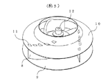
図3に示すように、羽根車2は、翼型羽根8と、この翼型羽根8を保持する芯板9および側板10とを有している。芯板9及び側板10は翼型羽根8の先端の外接円の径より大きい外径を有するよう形成される。風向板7の先端7aは翼型羽根8の先端の外接円と芯板9及び側板10外形との間に位置するよう配設される。すなわち、風向板7の先端7aは芯板9及び側板10の外周の縁より内側に入り込み、かつ、翼型羽根8の先端に接触しない位置に設けられる。ターボファン30の組立の作業性を向上するためには、羽根車2の側板10外径は羽根8外径より大きく、芯板9外径は羽根8外径とほぼ同一とすると、装置に羽根車2を組み込む際に、風向板7の先端7aが芯板9と接触しないため、モータ3への羽根車2の装着が容易になる。
【0016】
翼型羽根8は芯板9及び側板10の間に実質的に密着するよう固定される。具体的な固定方法としては、図3〜図5に示すように、翼型羽根8はかしめにより芯板9及び側板10に固定される。翼型羽根8にはかしめ固定のためのかしめ部11が芯板9及び側板10に面する側に突出するよう設けられ、一方、芯板9及び側板10にはこのかしめ部11が挿入されるよう穿設された羽根挿入部18が設けられる。翼型羽根8と芯板9及び側板10との間の隙間が小さくなり、実質的に密着する状態となるようかしめ部11を羽根挿入部18に挿入し、かしめ部11を折り曲げてかしめることにより翼型羽根8と芯板9及び側板10とが固定される。図4はかしめ部11がかしめられた状態の縦断面を示す。かしめ部11は同図に示されるように翼型羽根8の内側に向かって折曲げられ、これにより羽根挿入部18の外側の隙間が小さくなり、翼型羽根8と芯板9及び側板10とが実質的に密着してかしめ部からの空気の漏れが防止される。羽根挿入部18は羽根形状にあわせて設けられ、かしめ部11は高圧側と低圧側の羽根に交互に設けられるとともにそれぞれ羽根内部に向けて折曲げられるので、羽根8と芯板9と側板10の合せ面の隙間が小さくなり、実質的に密着状態となって空気の漏れによる損失を低減することができ、ターボファン30の効率を向上させることができる。
【0017】
図5に、翼型羽根8を一枚の板状部材から成形した例を示す。板状部材を成形して翼型断面を有するとともに羽根高圧側16、羽根低圧側17にそれぞれ曲面を有する翼型羽根8を形成する。羽根前縁部13は板状部材が曲面形状に形成されて空気の流入路を滑らかにする効果を有し、これによりファン効率の向上、低騒音化を図ることができる。一方、羽根後縁部14は板状部材の端部が鋭角状に接続されてスポット溶接等により固定されている。羽根前縁部13から羽根後縁部14に至る翼型羽根8の端部にはかしめ部11が突出するよう設けられる。図5ではかしめ部11が既に折り曲げられた状態で図示されているが、翼型羽根8を芯板9および側板10の羽根挿入部18に挿入する前は羽根高圧側16あるいは羽根低圧側17に連なる面で端部から突出している。
【0018】
本実施例の空気清浄装置はクリーンルーム天井面に組まれた縦600mm、横1200mmのシステム天井格子上に設置される。仕様の1例としては、モータ3は定格出力26Wの三相200V50Hz対応の誘導電動機であり、ターボファン30は羽根外径φ340で3枚の翼型羽根8を有する羽根車2とこのモータ3を組み合わせたものであり、フィルタ5としては定格風量18.5m3/min時の定格圧力損失が10.5mmAq以下(平均9.5mmAq)の高性能フィルタである。この組合せにお蹴る特性は図12に示されるようになり、吸込口周辺の機外静圧が29.4Pa(3mmAq)の状態で、フィルタ5下流側のクリーンルーム内へ平均風速0.3m/秒、風量13m3/分の送風性能で運転したときの消費電力は40Wである。このとき騒音は43〜42dBである。仕様の裕度は、フィルタ圧損のバラツキ、モータ、ファン等の部品精度のバラツキにより、風量は約±10%、消費電力は約±10%を許容範囲とする。
【0019】
本発明の第2の実施の形態を図6、図7により説明する。
【0020】
本実施の形態は、羽根車2を複数枚の板状部材を接合して成形された翼型羽根8と、この翼型羽根8を保持する芯板9および側板10とにより構成したものである。他の構成は第1の実施の形態と同様である。本実施の形態では翼型羽根8は2枚の板状部材を接合して成形される。2枚の板状部材の一方は羽根高圧側16になり、他方は羽根低圧側17になる。2枚の板状部材は組み合わされた状態で翼型断面を有するような形状に成形され、組合せにより羽根高圧側16、羽根低圧側17にそれぞれ曲面を有する翼型羽根8が形成される。羽根高圧側16には羽根前縁部13が形成され、羽根前縁部13は板状部材が曲面形状に形成されて空気の流入路を滑らかにする効果を有する。羽根低圧側17は羽根高圧側16から羽根前縁部13を除いたような形状に形成される。2枚の板状部材はそれぞれ羽根低圧側17、羽根高圧側16に成形された後に接合される。羽根高圧側16と羽根低圧側17の接合部15は羽根車2の回転方向に対して後ろ側、すなわち回転時に低圧となる羽根低圧側でかつ翼型羽根の前縁部13から少なくとも翼型羽根の最大厚さ以上離れた位置に配置される。接合部15は空気流が剥離しない程度のなめらかさを持ち、接合面は羽根前縁部13に対しては略平行で羽根後縁部14に対しては傾斜した状態に接合される。本実施の形態でも第1の実施の形態と同様にファン効率の向上、低騒音化を図ることができる。
【0021】
一方、羽根後縁部14は羽根高圧側16と羽根低圧側17の端部が鋭角状に接続されてスポット溶接等により固定されている。羽根前縁部13から羽根後縁部14に至る翼型羽根8の端部にはかしめ部11が突出するよう設けられる。図6、図7ではかしめ部11が既に折り曲げられた状態で図示されているが、翼型羽根8を芯板9および側板10の羽根挿入部18に挿入する前は羽根高圧側16あるいは羽根低圧側17に連なる面で端部から突出している。
【0022】
本実施の形態でも、羽根挿入部18は羽根形状にあわせて設けられ、かしめ部11は高圧側と低圧側の羽根に交互に設けられるとともにそれぞれ羽根内部に向けて折曲げられるので、羽根8と芯板9と側板10の合せ面の隙間が小さくなり、実質的に密着状態となって空気の漏れによる損失を低減することができ、ターボファン30の効率を向上させることができる。
【0023】
本発明の第3の実施の形態を図8により説明する。本実施例は、羽根車2の芯板9と側板10の補強のために、芯板9の外周部に一体成形リング19を設けたものである。本実施の形態の羽根車2は、図8に示されるように、翼型羽根8の側板側内径D1sと羽根外径D2sの内外径比(D1s/D2s)が0.59〜0.76の範囲に設定される。他の構成は第1の実施の形態又は第2の実施の形態と同様である。
【0024】
本発明の第4の実施の形態を図10、図11により説明する。本実施の形態は風向板7の先端部7aの幅を他の部分より狭くして、先端部7aを羽根8の外接円の近傍まで挿入できるようにしたものである。図10は芯板9と側板10の外形がいずれも羽根8の外接円の径より大きいターボファンの場合であり、図11は側板10の径が羽根8の外接円の径より大きく、芯板9の径が羽根8の外接円の径とほぼ同一なターボファンの場合である。他の部分は第1の実施の形態又は第2の実施の形態と同様である。
【0025】
【発明の効果】
本発明によれば、高効率でエネルギー消費が少ない空気清浄装置を得ることができる。
【図面の簡単な説明】
【図1】本発明の第1の実施の形態における空気清浄装置の構成を示す縦断面図である。
【図2】本発明の第1の実施の形態における空気清浄装置の構成を示す平面図である。
【図3】本発明の第1の実施の形態における空気清浄装置に用いられるターボファンの羽根車の構成を示す斜視図である。
【図4】本発明の第1の実施の形態における空気清浄装置のターボファンの翼型羽根のカシメ部を示す縦断面図である。
【図5】本発明の第1の実施の形態における空気清浄装置のターボファンの一枚板から成形した翼型羽根を示す斜視図である。
【図6】本発明の第2の実施の形態における空気清浄装置のターボファンの二枚板を接合して成形した翼型羽根を示す斜視図である。
【図7】本発明の第2の実施の形態における空気清浄装置のターボファンの二枚板を接合して成形した翼型羽根を示す斜視図である。
【図8】本発明の第3の実施の形態における空気清浄装置のターボファンの側板、芯板の外周に一体成形リングをつけた構成を示す縦断面図である。
【図9】従来のターボファンに用いられた平板から成形された羽根の形状を示す斜視図である。
【図10】本発明の第4の実施の形態における空気清浄装置の羽根車と風向板の位置関係を示す要部縦断面図である。
【図11】本発明の第1の実施の形態における空気清浄装置の羽根車と風向板の位置関係を示す要部縦断面図である。
【図12】本発明の第1の実施の形態における空気清浄装置の風量−静圧(Q−H)特性と風量−消費電力特性、フィルタ圧損特性の1例を示した特性図である。
【符号の説明】
1…ハウジング,1a…第2の面,1b…側面,2…羽根車,2a…羽根車吹き出し口上面,2b…羽根車吸込口,2c…羽根車吹き出し口,3…モータ,4,4a…モータベース,5…フィルタ,6…ベルマウス,7…風向板,7a…風向板曲面部,8…翼型羽根,9…芯板,10…側板,11…かしめ部,12…ボス部,13…羽根前縁部,14…羽根後縁部,15…羽根接合部,16…羽根高圧側,17…羽根低圧側,18…羽根挿入口,19…羽根外周リング部,20…羽根側板側内径,21…羽根外径。[0001]
BACKGROUND OF THE INVENTION
The present invention relates to an air purifier installed on a ceiling surface of a clean room for manufacturing semiconductors and liquid crystals, and a general apparatus using a turbofan for the purpose of improving the efficiency of a blower and reducing noise in a self-supporting clean booth and a clean bench.
[0002]
[Prior art]
Conventionally, the blades of a turbofan have a shape in which a single flat plate is curved on a two-dimensional plane as shown in FIG.
[0003]
In addition, an impeller having a large number of blades was used to obtain a necessary static pressure only with a turbofan.
[0004]
[Problems to be solved by the invention]
Conventionally, the blades of a turbofan have a shape in which a single flat plate is curved in a two-dimensional plane, so the leading edge of the blades is cut off, noise is increased by wind noise, loss is high, and fan efficiency is high. It was not obtained.
[0005]
Further, if the wind direction plate is not provided, the static pressure cannot be recovered, and a large number of blades are required to obtain the required static pressure with only the turbofan. Thus, when the number of blades increases, the flow path loss of the air flow along the blades increases as the number of blades increases.
[0006]
An object of the present invention is to provide an air purifying apparatus with high efficiency and low energy consumption.
[0007]
[Means for Solving the Problems]
The present invention, in order to solve the above problems, a turbofan having a motor for rotating the impeller and the impeller, and a bell mouth for supplying air to the suction port of the turbo fan, blown from the turbofan a filter for cleaning the air, the air cleaning apparatus that includes a housing having a pressure chamber for guiding the air blown out from the turbo fan to pressurize the filter therein, the turbofan is stored in the housing is, the housing and the motor base having an opening for blowing to supply air blown from the centrifugal impeller is fixed to the motor to the filter, and a wind direction plate that is disposed proximate to said impeller provided therein, wherein the impeller includes a blade-type blades molded from a single plate-like member and a core plate and side plates for holding the wing type blade The plate-like member is disposed at a position behind the rotation direction of the impeller and away from the edge of the airfoil blade, and the airfoil blade is disposed between the core plate and the side plate. The impeller has airfoil-shaped blades and the number of blades is 4 or less.
[0008]
The impeller includes a core plate and side plates for holding said airfoil vane and said airfoil vane, the core plate and the side plates to have a diameter larger than the outer diameter of the circumscribed circle of the tip of the airfoil blade formed is, the airfoil vane is fixed to substantially close contact with the core plate and the side plates, the tip of the wind direction plate between the circumscribed circle and the core plate and the side plate outer shape of the tip of the airfoil blade It is arranged to be positioned.
[0009]
The wind direction plate, wherein the side close to the airfoil vane is formed to have a cross-section of curved shape.
[0010]
In the air cleaning device, the turbo fan is stored in the housing, external static pressure 29.4Pa ± 10%, the mean balloon wind speed 0.3 m / sec ± 10% from the filter, the air volume 13M3 / min ± 10 %, The power consumption is 40 W ± 10%.
[0012]
DETAILED DESCRIPTION OF THE INVENTION
Embodiments of the present invention will be described with reference to FIGS. 1 to 8 and FIGS. A first embodiment of the present invention will be described with reference to FIGS. 1 to 5 and FIG.
[0013]
As shown in FIGS. 1 and 2, the air purifier of the present embodiment supplies air to the
[0014]
In this embodiment, as shown in FIGS. 1 and 2, the
[0015]
As shown in FIG. 3, the
[0016]
The
[0017]
FIG. 5 shows an example in which the
[0018]
The air purifying apparatus of the present embodiment is installed on a system ceiling grid of 600 mm in length and 1200 mm in width assembled on the ceiling surface of the clean room. As an example of the specification, the
[0019]
A second embodiment of the present invention will be described with reference to FIGS.
[0020]
In the present embodiment, the
[0021]
On the other hand, the blade trailing
[0022]
Also in the present embodiment, the
[0023]
A third embodiment of the present invention will be described with reference to FIG. In this embodiment, in order to reinforce the
[0024]
A fourth embodiment of the present invention will be described with reference to FIGS. In this embodiment, the width of the tip portion 7a of the
[0025]
【The invention's effect】
According to the present invention, it is possible to obtain an air cleaning device with high efficiency and low energy consumption.
[Brief description of the drawings]
FIG. 1 is a longitudinal sectional view showing a configuration of an air cleaning device according to a first embodiment of the present invention.
FIG. 2 is a plan view showing the configuration of the air cleaning device according to the first embodiment of the present invention.
FIG. 3 is a perspective view showing a configuration of an impeller of a turbofan used in the air cleaning device according to the first embodiment of the present invention.
FIG. 4 is a longitudinal sectional view showing a caulking portion of a wing blade of a turbofan of the air cleaning device according to the first embodiment of the present invention.
FIG. 5 is a perspective view showing airfoil blades formed from a single plate of a turbofan of the air cleaning device according to the first embodiment of the present invention.
FIG. 6 is a perspective view showing an airfoil blade formed by joining two turbofan two plates of an air cleaning device according to a second embodiment of the present invention.
FIG. 7 is a perspective view showing an airfoil blade formed by joining two turbofan two plates of an air cleaning device according to a second embodiment of the present invention.
FIG. 8 is a longitudinal sectional view showing a configuration in which an integrally molded ring is attached to the outer periphery of a side plate and a core plate of a turbofan of an air cleaning device according to a third embodiment of the present invention.
FIG. 9 is a perspective view showing the shape of a blade formed from a flat plate used in a conventional turbofan.
FIG. 10 is a longitudinal sectional view of a main part showing a positional relationship between an impeller and a wind direction plate of an air cleaning device according to a fourth embodiment of the present invention.
FIG. 11 is a longitudinal sectional view of the main part showing the positional relationship between the impeller and the wind direction plate of the air cleaning device according to the first embodiment of the present invention.
FIG. 12 is a characteristic diagram showing an example of an air volume-static pressure (QH) characteristic, an air volume-power consumption characteristic, and a filter pressure loss characteristic of the air cleaning device according to the first embodiment of the present invention.
[Explanation of symbols]
DESCRIPTION OF
Claims (4)
該ターボファンの吸込口に空気を供給するベルマウスと、
前記ターボファンから吹き出された空気を清浄化するフィルタと、
前記ターボファンから吹き出された空気を加圧して前記フィルタに導く加圧室を内部に有するハウジングとを備えた空気清浄装置において、
前記ターボファンは前記ハウジング内に格納され、
前記ハウジングは、前記モータを固定し、前記羽根車から吹き出された空気を前記フィルタに供給するよう吹き出す開口部を有するモータベースと、前記羽根車に近接して配設された風向板とをその内部に備え、
前記羽根車は、1枚の板状部材から成形された翼型羽根と、該翼型羽根を保持する芯板および側板とを備え、
前記板状部材の接合部は前記羽根車の回転方向に対して後ろ側でかつ前記翼型羽根の縁部から離れた位置に配置され、
前記翼型羽根を前記芯板及び前記側板の間に実質的に密着させて固定し、
前記羽根車は翼型形状羽根を有するとともに羽根枚数が4枚以下であることを特徴とする空気清浄装置。A turbofan having a motor for rotating the impeller and the impeller,
A bell mouth for supplying air to the suction port of the turbo fan,
A filter for cleaning the air blown from the turbofan,
In the air cleaning apparatus that includes a housing having a pressure chamber for guiding the air blown out from the turbo fan to pressurize the filter therein,
The turbofan is stored in the housing,
The housing is to fix the motor, the motor base having an opening for blowing to supply air blown from the impeller to the filter, and a wind direction plate that is disposed proximate to said impeller Prepare for the inside,
The impeller includes an airfoil blade formed from a single plate-like member, a core plate and a side plate for holding the airfoil blade,
The joint part of the plate-like member is arranged on the rear side with respect to the rotation direction of the impeller and at a position away from the edge of the wing blade,
Fixing the airfoil blade in close contact with the core plate and the side plate,
The impeller has airfoil-shaped blades, and the number of blades is 4 or less.
前記ターボファンは前記ハウジング内に格納され、機外静圧29.4Pa±10%、前記フィルタからの平均吹き出し風速0.3m/秒±10%、風量13m3/分±10%のときに消費電力40W±10%となるよう構成されたことを特徴とする請求項1記載の空気清浄装置。In the air cleaning device,
The turbofan is housed in the housing and consumes power when the external static pressure is 29.4 Pa ± 10%, the average blown air velocity from the filter is 0.3 m / sec ± 10%, and the air volume is 13 m3 / min ± 10%. The air purifier according to claim 1, wherein the air purifier is configured to be 40 W ± 10%.
Priority Applications (5)
| Application Number | Priority Date | Filing Date | Title |
|---|---|---|---|
| JP27079497A JP3774552B2 (en) | 1997-10-03 | 1997-10-03 | Air purifier |
| US09/164,582 US6156090A (en) | 1997-10-03 | 1998-10-01 | Air cleaner having vanes with a winglike cross-section between a shroud and baseplate for rotation within a housing |
| KR1019980041683A KR100322829B1 (en) | 1997-10-03 | 1998-10-02 | Air cleaner |
| TW087116446A TW367401B (en) | 1997-10-03 | 1998-10-02 | Air cleaner |
| DE19845501A DE19845501B4 (en) | 1997-10-03 | 1998-10-02 | Fan unit for an air cleaner |
Applications Claiming Priority (1)
| Application Number | Priority Date | Filing Date | Title |
|---|---|---|---|
| JP27079497A JP3774552B2 (en) | 1997-10-03 | 1997-10-03 | Air purifier |
Publications (2)
| Publication Number | Publication Date |
|---|---|
| JPH11108403A JPH11108403A (en) | 1999-04-23 |
| JP3774552B2 true JP3774552B2 (en) | 2006-05-17 |
Family
ID=17491107
Family Applications (1)
| Application Number | Title | Priority Date | Filing Date |
|---|---|---|---|
| JP27079497A Expired - Fee Related JP3774552B2 (en) | 1997-10-03 | 1997-10-03 | Air purifier |
Country Status (1)
| Country | Link |
|---|---|
| JP (1) | JP3774552B2 (en) |
Families Citing this family (3)
| Publication number | Priority date | Publication date | Assignee | Title |
|---|---|---|---|---|
| JP5522306B1 (en) | 2012-12-21 | 2014-06-18 | ダイキン工業株式会社 | Centrifugal fan |
| KR101769817B1 (en) * | 2015-10-30 | 2017-08-30 | 엘지전자 주식회사 | apparatus for both humidification and air cleaning |
| CN114484839B (en) * | 2021-12-10 | 2023-05-23 | 惠瑞净化科技(江苏)有限公司 | Install high-efficient supply-air outlet of sealed on lithium cell toilet roof |
-
1997
- 1997-10-03 JP JP27079497A patent/JP3774552B2/en not_active Expired - Fee Related
Also Published As
| Publication number | Publication date |
|---|---|
| JPH11108403A (en) | 1999-04-23 |
Similar Documents
| Publication | Publication Date | Title |
|---|---|---|
| JP3092554B2 (en) | Centrifugal blower, method for manufacturing the same, and air conditioner equipped with the centrifugal blower | |
| EP1016790A3 (en) | Stator or axial flow fan | |
| CN100485193C (en) | Blower | |
| JP4859204B2 (en) | Centrifugal fan and air conditioner equipped with the same | |
| US5743710A (en) | Streamlined annular volute for centrifugal blower | |
| WO2011114375A1 (en) | Cross-flow fan and air conditioner | |
| JP3050144B2 (en) | Axial fan | |
| KR20080003444A (en) | Centrifugal blower and air conditioner using the same | |
| JP4505885B2 (en) | Blower, air conditioner using the same, and air purifier | |
| JP3774552B2 (en) | Air purifier | |
| JP4832498B2 (en) | Cross-flow fan and air conditioner | |
| JPH07247991A (en) | Diagonal flow fan | |
| JPH09195988A (en) | Multiblade blower | |
| JP2001280288A (en) | Impeller structure of multiblade blower | |
| JP4512352B2 (en) | Pipe fan | |
| CN100406747C (en) | Air intake construction of axial flow fan | |
| JP2000345995A (en) | Fan | |
| JP3311526B2 (en) | Axial blower | |
| JPH05296195A (en) | Axial fan | |
| JP4857495B2 (en) | Impeller of multi-blade fan and multi-blade fan equipped with the impeller | |
| JP4140086B2 (en) | Electric blower | |
| JPS60169699A (en) | Vane wheel of multiblade blower | |
| JP3938252B2 (en) | Multi-blade blower | |
| JP2929834B2 (en) | Centrifugal fan | |
| JP2707756B2 (en) | Electric blower |
Legal Events
| Date | Code | Title | Description |
|---|---|---|---|
| A977 | Report on retrieval |
Free format text: JAPANESE INTERMEDIATE CODE: A971007 Effective date: 20050324 |
|
| A131 | Notification of reasons for refusal |
Free format text: JAPANESE INTERMEDIATE CODE: A131 Effective date: 20050628 |
|
| A521 | Request for written amendment filed |
Free format text: JAPANESE INTERMEDIATE CODE: A523 Effective date: 20050829 |
|
| TRDD | Decision of grant or rejection written | ||
| A01 | Written decision to grant a patent or to grant a registration (utility model) |
Free format text: JAPANESE INTERMEDIATE CODE: A01 Effective date: 20060207 |
|
| A61 | First payment of annual fees (during grant procedure) |
Free format text: JAPANESE INTERMEDIATE CODE: A61 Effective date: 20060220 |
|
| R150 | Certificate of patent or registration of utility model |
Free format text: JAPANESE INTERMEDIATE CODE: R150 |
|
| FPAY | Renewal fee payment (event date is renewal date of database) |
Free format text: PAYMENT UNTIL: 20090224 Year of fee payment: 3 |
|
| FPAY | Renewal fee payment (event date is renewal date of database) |
Free format text: PAYMENT UNTIL: 20100224 Year of fee payment: 4 |
|
| FPAY | Renewal fee payment (event date is renewal date of database) |
Free format text: PAYMENT UNTIL: 20100224 Year of fee payment: 4 |
|
| FPAY | Renewal fee payment (event date is renewal date of database) |
Free format text: PAYMENT UNTIL: 20110224 Year of fee payment: 5 |
|
| FPAY | Renewal fee payment (event date is renewal date of database) |
Free format text: PAYMENT UNTIL: 20120224 Year of fee payment: 6 |
|
| FPAY | Renewal fee payment (event date is renewal date of database) |
Free format text: PAYMENT UNTIL: 20120224 Year of fee payment: 6 |
|
| FPAY | Renewal fee payment (event date is renewal date of database) |
Free format text: PAYMENT UNTIL: 20130224 Year of fee payment: 7 |
|
| FPAY | Renewal fee payment (event date is renewal date of database) |
Free format text: PAYMENT UNTIL: 20130224 Year of fee payment: 7 |
|
| FPAY | Renewal fee payment (event date is renewal date of database) |
Free format text: PAYMENT UNTIL: 20140224 Year of fee payment: 8 |
|
| LAPS | Cancellation because of no payment of annual fees |