JP3772691B2 - Pulse wave detector - Google Patents
Pulse wave detector Download PDFInfo
- Publication number
- JP3772691B2 JP3772691B2 JP2001138064A JP2001138064A JP3772691B2 JP 3772691 B2 JP3772691 B2 JP 3772691B2 JP 2001138064 A JP2001138064 A JP 2001138064A JP 2001138064 A JP2001138064 A JP 2001138064A JP 3772691 B2 JP3772691 B2 JP 3772691B2
- Authority
- JP
- Japan
- Prior art keywords
- pressure
- sensitive element
- artery
- element group
- sensitive
- Prior art date
- Legal status (The legal status is an assumption and is not a legal conclusion. Google has not performed a legal analysis and makes no representation as to the accuracy of the status listed.)
- Expired - Fee Related
Links
Images
Landscapes
- Measuring Pulse, Heart Rate, Blood Pressure Or Blood Flow (AREA)
Description
【0001】
【発明の属する技術分野】
この発明は、生体表面から動脈の脈動を検出する脈波検出装置に関する。
【0002】
【従来の技術】
生体(特に手首)の表面に感圧素子を押圧して手首動脈の脈波を検出する脈波検出装置として、従来、動脈径よりも小さい幅の感圧素子を動脈と交差する方向に複数個並べ、この感圧素子を手首表面に押圧し、動脈直上の感圧素子の出力を検出するものがある。例えば特公平8−2351号公報:「脈波検出装置」では、多数の感圧ダイオードを動脈と略直角に交差する方向に一定の間隔を隔てて形成してある。
【0003】
【発明が解決しようとする課題】
しかしながら、従来の脈波検出装置によれば、図9に概略的に示すように、脈波検出装置を手首に装着したとき、複数個の感圧素子61を有する感圧素子群60のうち、動脈50の中央部Cに必ず1つの感圧素子61′が位置するように、複数個(ここでは10個)の感圧素子61が隙間無く配置されているため、非常に多くの感圧素子が必要となる。感圧素子は高価なものであるため、これを多数用いるとコスト高になるという問題がある。
【0004】
この発明は、そのような問題点に着目してなされたものであって、必要な感圧素子の個数を少なくすることによりコストを削減した脈波検出装置を提供することを目的としている。
【0005】
【課題を解決するための手段】
前記目的を達成するために、この発明の脈波検出装置は、生体動脈の脈動を検出する複数個の感圧素子を有する感圧素子群と、この感圧素子群を生体に装着する生体装着手段と、感圧素子群を生体動脈に押圧する押圧手段とを備えるものにおいて、前記感圧素子群は、複数個の感圧素子が動脈と交差する方向に並べられてなり、この感圧素子群の感圧素子のうち、最大出力の第1の感圧素子を抽出し、前記第1の感圧素子の両隣の感圧素子の出力がほぼ同レベルとなるように、感圧素子群を押圧方向と交差する方向の平面上で回転させる手段を備え、この回転手段により感圧素子群を回転させたとき、前記両隣の感圧素子の出力がほぼ同レベルの場合、前記第1の感圧素子を動脈中央部に位置する感圧素子と決定することを特徴とする。
【0006】
この脈波検出装置では、感圧素子群の感圧素子のうち、抽出した最大出力の第1の感圧素子の両隣の感圧素子の出力がほぼ同レベルとなるように、回転手段により感圧素子群を回転させることができるため、動脈中央部に対して回転角によって感圧素子の間隔(ピッチ)が相対的に変化する。そのため、感圧素子の個数が少なくても、回転角の制御でいずれかの感圧素子を動脈中央部に位置決めすることができ、コストを削減できる。
【0007】
感圧素子群の感圧素子のうち、動脈中央部に最も近い波形を出力する第1の感圧素子が動脈中央部に位置したかどうかは、例えば、最大出力の感圧素子の両隣の感圧素子の出力を比べればよい。即ち、両隣の感圧素子の出力波形がほぼ同レベルの場合、その最大出力(第1)の感圧素子を動脈中央部に位置する感圧素子と決定する。これは、動脈上に感圧素子が位置しても、動脈中央部での脈動が最も大きく、中央部からずれるほど脈動が小さくなるからである。従って、両隣の感圧素子の出力波形がほぼ同じであるということは、その両隣の感圧素子の間に位置する第1の感圧素子が動脈中央部に位置することになる。
【0008】
また、感圧素子群の回転方向は、その回転中心と動脈中央部との位置関係により選択するのが好ましい。具体的には、感圧素子群が生体動脈に押圧されたとき、動脈が感圧素子群の回転中心よりも右側に位置するときは、感圧素子群を左回りに回転させ、動脈が感圧素子群の左側に位置するときは、感圧素子群を右回りに回転させる。これにより、いずれの場合も、生体の末梢側で感圧素子が動脈中央部に位置することになる。
【0009】
これは、後記のように、生体内の動脈は、心臓側よりも末梢側の方が生体表面から浅い部位に存在するので、生体表面に近い動脈部位で脈波を検出する方が脈波検出の精度が向上するからである。
【0010】
【発明の実施の形態】
以下、実施の形態により、この発明を更に詳細に説明する。
【0011】
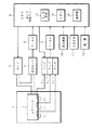
図1は、実施形態に係る脈波検出装置の構成を示すブロック図である。この脈波検出装置は、押圧手段としてのエアバッグ2と、複数個(ここでは便宜上3個)の感圧素子3A ,3B ,3C を有する感圧素子群(符号は付せず)と、感圧素子群を生体に装着する生体装着手段(ベルト等)1と、感圧素子3A ,3B ,3C の各出力を増幅するアンプ4A ,4B ,4C と、フィルタ5と、A/D変換器13、メモリ14及び演算部15を内蔵するCPU6と、エアバッグ2を加圧するためのポンプ7と、エアバッグ2の圧力を検出する圧力センサ8と、フィルタ9と、表示装置10と、入力スイッチ11と、電源12とを備えている。最も、このような構成の脈波検出装置自体は、既に一般によく知られたものと変わるところはない。
【0012】
この脈波検出装置では、複数個の感圧素子を有する感圧素子群のうちの1つの感圧素子が動脈中央部に位置するように、感圧素子群を押圧方向と交差する方向の平面上で回転させる手段を設けたことが特徴である。
【0013】
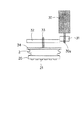
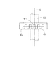
その感圧素子群を回転させる手段の一例を図2に概略図で示す。この回転手段は、駆動源としてモータ(ステッピングモータ)30を使用し、モータ30の回転軸30aに小歯車31を取付け、小歯車31に支軸33の一端部に取付けた大歯車32を歯合させ、支軸33の他端部にプレート34を取付けてなる。そして、プレート34にエアバッグ2が固定され、エアバッグ2の押圧面側に複数個(6個)の感圧素子21を有する感圧素子群20が取付けられている。従って、モータ30が作動すれば、感圧素子群20は、押圧方向と交差する方向の平面上で回転する。
【0014】
なお、感圧素子群20の回転により1個の感圧素子21が動脈中央部に位置すればよいので、感圧素子群20は所定角αずつ回転するように設定されている。その所定角αは、例えば3〜10°である。
【0015】
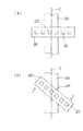
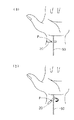
この感圧素子群20の回転と動脈中央部との位置関係について、図3を参照して説明する。脈波検出装置を生体(手首)表面に生体装着手段により装着すると、感圧素子群20は図3の(a)のように手首内部の動脈50に対して配置される。この感圧素子群20は、間隔を置いて6個の感圧素子21を有する。各部の寸法の具体例を示すと、感圧素子21の幅(動脈中央部Cに直交する方向の長さ)は、100μm〜1mm、感圧素子21の間隔(ピッチ)は、200μm〜2mmである。また、特に手首の橈骨動脈50の径が約3mmとすると、この動脈50の横断方向に約2個の感圧素子21が位置するように設定する。
【0016】
この感圧素子群20では感圧素子21の個数が少ないため、脈波検出装置を手首に装着した時点では、動脈中央部Cに感圧素子21が位置する可能性は低く、図3の(a)では、感圧素子21′が動脈中央部Cに最も近い位置にある。つまり、感圧素子21′の出力が最も高い。そこで、図3の(b)のように、感圧素子群20を矢印方向に回転させ、回転後に最大出力の感圧素子21′の両隣の感圧素子の出力を比較し、出力がほぼ同レベルの場合、感圧素子21′を動脈中央部Cに位置する感圧素子と決定する。勿論、装着当初から両隣の感圧素子の出力が同レベルであるときは、装着時点で既に1つの感圧素子が動脈中央部Cに位置していることになるので、感圧素子群20を回転させる必要はない。
【0017】
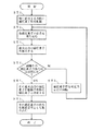
次に、感圧素子21′が動脈中央部Cに存在するか否かの判定処理を含む脈波検出処理について、図4のフロー図を参照して説明する。
【0018】
まず、ステップST1において、脈波検出装置を手首に装着する。即ち、手首内側に対して感圧素子群20を腕に直交する方向に配置する。次いで、ステップST2において、各感圧素子21の出力を取り込み、ステップST3において、そのうち最大出力の感圧素子21を抽出する。図3に示した例では、感圧素子21′がそれに該当する。
【0019】
そして、ステップST4において、その最大出力の感圧素子21′の両隣の感圧素子の出力がほぼ同じであるか否かを判定する。出力がほぼ同じである場合は、感圧素子21′が動脈中央部Cに位置すること〔図3の(b)の状態〕になるので、ステップST5において、その最大出力の感圧素子21′を動脈中央部Cに位置する感圧素子と決定する。続いて、その感圧素子21′の出力を脈波信号として取り込み、当該脈波検出処理を終了する。
【0020】
一方、ステップST4において、出力が同じでない場合は、感圧素子21′が動脈中央部Cに位置していないので、ステップST7に移行し、感圧素子群20を前記所定角αだけ回転させる。その後、ステップST2に戻り、再び回転後の各感圧素子21の出力を取り込み、前記と同じ処理を繰り返す。感圧素子群20の所定角αの回転は、両隣の感圧素子の出力がほぼ同じになるまで続ける。
【0021】
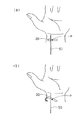
上記実施形態では、感圧素子群20の回転方向は特定しなかったが、前記したとおり、感圧素子21は生体末梢側の動脈部位に位置するのが好ましい。これには、図5の(a)に示すように、感圧素子群20を動脈50に配置した場合、動脈50が感圧素子群20の回転中心Pよりも右側に位置するときは、感圧素子群20を左回りに回転させる〔図5の(b)〕。反対に、図6の(a)に示すように、動脈50が感圧素子群20の回転中心Pよりも左側に位置するときは、感圧素子群20を右回りに回転させる〔図6の(b)〕。
【0022】
これにより、いずれの場合も、生体の末梢側(掌側)で感圧素子21が動脈中央部Cに位置することになる。
【0023】
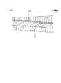
これは、前記したように、生体内の動脈は、心臓側よりも末梢側の方が生体表面から浅い部位に存在するので、生体表面に近い動脈部位で脈波を検出する方が脈波検出の精度が向上するからである。手首では、図7に示すように、橈骨51に沿って橈骨動脈50が存在するが、橈骨動脈50は末梢側(掌側)で浅い部位に存在するので、末梢側の動脈50の部位で脈波を検出する方がよいのである。
【0024】
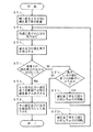
その感圧素子群20の回転方向を選択する処理を含む脈波検出処理について、図8のフロー図を参照して説明する。但し、図4のフロー図と同じ処理には同一のステップ番号を付してある。
【0025】
まず、ステップST1において、手首内側に対して感圧素子群20を腕に直交する方向に配置する。次いで、ステップST2において、各感圧素子21の出力を取り込み、ステップST3において、そのうち最大出力の感圧素子(最も動脈中央部Cに近いもの)21を抽出する。
【0026】
そして、ステップST4において、その最大出力の感圧素子21の両隣の感圧素子の出力がほぼ同じであるか否かを判定する。出力がほぼ同じである場合は、最大出力の感圧素子21が動脈中央部Cに位置することになるので、ステップST5において、その最大出力の感圧素子21を動脈中央部Cに位置する感圧素子と決定する。続いて、その最大出力の感圧素子21の出力を脈波信号として取り込み、当該脈波検出処理を終了する。
【0027】
一方、ステップST4において、出力が同じでない場合は、最大出力の感圧素子21が動脈中央部Cに位置していないので、ステップST8に移行する。ステップST8においては、最大出力の感圧素子21が感圧素子群20の回転中心Pよりも右であるか否かを判定する。つまり、動脈中央部Cが回転中心Pよりも右側に位置するかどうかを判定する。この判定がYESの場合〔図5の(a)の状態〕、ステップST9において、感圧素子群20を左回りに所定角αだけ回転させる〔図5の(b)〕。ステップST8の判定がNOの場合〔図6の(a)の状態〕、ステップST10にスキップし、感圧素子群20を右回りに所定角αだけ回転させる〔図6の(b)〕。
【0028】
ステップST9,ST10で感圧素子群20を所定角αだけ回転させた後は、ステップST2に戻り、再び回転後の各感圧素子21の出力を取り込み、前記処理を繰り返す。ここでも感圧素子群20の所定角αの回転は、両隣の感圧素子の出力がほぼ同じになるまで続ける。
【0029】
なお、上記実施形態において、感圧素子21の個数は一例であり、6個よりも多くても少なくてもよい。
【0030】
【発明の効果】
以上説明したように、本発明の脈波検出装置によれば、感圧素子群の感圧素子のうち、最大出力の第1の感圧素子を抽出し、この第1の感圧素子の両隣の感圧素子の出力がほぼ同レベルとなるように、回転手段により感圧素子群を回転させることができるため、両隣の感圧素子の出力がほぼ同レベルとなった場合に、第1の感圧素子を動脈中央部に位置決めすることができる。
また、回転手段により感圧素子群を回転させることにより、動脈中央部に対して回転角によって感圧素子の間隔(ピッチ)が相対的に変化するので、すなわちそのピッチは、感圧素子群が動脈中央部に直交する方向に位置するときよりも、感圧素子群の回転により第1の感圧素子と両隣の感圧素子が動脈中央部に近づくほど動脈中央部に対して相対的に小さくなるので、第1の感圧素子と両隣の感圧素子の出力を精度良く得ることができる。
従って、感圧素子の個数が少なくても第1の感圧素子を動脈中央部に精度良く位置させることができるとともに、感圧素子の個数の低減によりコストを削減できる。
【図面の簡単な説明】
【図1】実施形態に係る脈波検出装置の構成を示すブロック図である。
【図2】同脈波検出装置における感圧素子群と回転手段を示す概略図である。
【図3】同脈波検出装置における感圧素子群と動脈中央部との位置関係を示す図であり、感圧素子群を動脈に配置したときの図(a)、及び感圧素子群を回転させたときの図(b)である。
【図4】同脈波検出装置の脈波検出動作(感圧素子群の回転処理を含む)を示すフロー図である。
【図5】同脈波検出装置における感圧素子群の回転方向と動脈との位置関係を示す図であり、動脈中央部が感圧素子群の回転中心より右側に位置するときの図(a)、及び感圧素子群を左回りに回転させたときの図(b)である。
【図6】同脈波検出装置における感圧素子群の回転方向と動脈との位置関係を示す図であり、動脈中央部が感圧素子群の回転中心より左側に位置するときの図(a)、及び感圧素子群を右回りに回転させたときの図(b)である。
【図7】生体(手首)での動脈位置を説明するための縦断面図である。
【図8】同脈波検出装置の脈波検出動作(感圧素子群の回転方向の選択処理を含む)を示すフロー図である。
【図9】従来例に係る脈波検出装置における感圧素子群と動脈中央部との位置関係を示す図である。
【符号の説明】
1 生体装着手段
2 エアバッグ
3A ,3B ,3C 感圧素子
20 感圧素子群
21 感圧素子
21′ 最大出力の感圧素子
30 モータ
31,32 歯車
34 プレート
50 動脈
C 動脈中央部
P 感圧素子群の回転中心[0001]
BACKGROUND OF THE INVENTION
The present invention relates to a pulse wave detection device that detects pulsation of an artery from the surface of a living body.
[0002]
[Prior art]
2. Description of the Related Art Conventionally, as a pulse wave detection device that detects a pulse wave of a wrist artery by pressing a pressure sensitive element on the surface of a living body (especially a wrist), a plurality of pressure sensitive elements having a width smaller than the diameter of the artery are conventionally crossed There is an apparatus that detects the output of the pressure sensitive element directly above the artery by pressing the pressure sensitive element against the wrist surface. For example, in Japanese Patent Publication No. 8-2351: “Pulse wave detection device”, a large number of pressure-sensitive diodes are formed at regular intervals in a direction intersecting at a right angle with an artery.
[0003]
[Problems to be solved by the invention]
However, according to the conventional pulse wave detection device, as schematically shown in FIG. 9, when the pulse wave detection device is worn on the wrist, among the pressure
[0004]
The present invention has been made paying attention to such problems, and an object of the present invention is to provide a pulse wave detection device with a reduced cost by reducing the number of necessary pressure sensitive elements.
[0005]
[Means for Solving the Problems]
In order to achieve the above object, a pulse wave detection device according to the present invention comprises a pressure-sensitive element group having a plurality of pressure-sensitive elements for detecting pulsation of a living artery, and a living-body mounting for mounting the pressure-sensitive element group on a living body. And pressure means for pressing the pressure sensitive element group against the living artery, wherein the pressure sensitive element group is formed by arranging a plurality of pressure sensitive elements in a direction intersecting the artery. The first pressure-sensitive element having the maximum output is extracted from the pressure-sensitive elements of the group, and the pressure-sensitive element group is selected so that the outputs of the pressure-sensitive elements on both sides of the first pressure-sensitive element are approximately at the same level. comprising a means for rotating on the direction of the plane intersecting the pressing direction, when rotating the pressure-sensitive element group by the rotating means, when the output of the pressure-sensitive element of the neighboring are almost the same level, the first sensitive The pressure element is determined to be a pressure sensitive element located in the center of the artery.
[0006]
In this pulse wave detection device, the rotating means senses the output so that the outputs of the pressure sensitive elements adjacent to the extracted first pressure sensitive element of the maximum output among the pressure sensitive elements in the group of pressure sensitive elements are substantially at the same level. Since the pressure element group can be rotated, the interval (pitch) of the pressure sensitive elements changes relatively with the rotation angle with respect to the central portion of the artery. Therefore, even if the number of pressure sensitive elements is small, any pressure sensitive element can be positioned in the central portion of the artery by controlling the rotation angle, and the cost can be reduced.
[0007]
Whether the first pressure-sensitive element that outputs the waveform closest to the central part of the artery among the pressure-sensitive elements in the group of pressure-sensitive elements is positioned in the central part of the artery, for example, What is necessary is just to compare the output of a pressure element. That is, when the output waveforms of the pressure sensitive elements on both sides are substantially at the same level, the pressure sensitive element with the maximum output (first) is determined as the pressure sensitive element located in the center of the artery. This is because, even if the pressure sensitive element is located on the artery, the pulsation is the largest in the central part of the artery, and the pulsation becomes smaller as it deviates from the central part. Therefore, the fact that the output waveforms of the two adjacent pressure sensitive elements are substantially the same means that the first pressure sensitive element located between the two adjacent pressure sensitive elements is located in the center of the artery.
[0008]
The rotation direction of the pressure-sensitive element group is preferably selected according to the positional relationship between the rotation center and the central part of the artery. Specifically, when the pressure-sensitive element group is pressed against the living artery, if the artery is located on the right side of the rotation center of the pressure-sensitive element group, the pressure-sensitive element group is rotated counterclockwise to sense the artery. When located on the left side of the pressure element group, the pressure sensitive element group is rotated clockwise. Thereby, in any case, the pressure sensitive element is located in the central part of the artery on the peripheral side of the living body.
[0009]
This is because, as will be described later, in the arteries in the living body, the distal side rather than the heart side exists in a shallower part from the living body surface. Therefore, it is better to detect the pulse wave at the arterial part closer to the living body surface. This is because the accuracy of the is improved.
[0010]
DETAILED DESCRIPTION OF THE INVENTION
Hereinafter, the present invention will be described in more detail with reference to embodiments.
[0011]
FIG. 1 is a block diagram illustrating a configuration of a pulse wave detection device according to the embodiment. This pulse wave detection device includes an
[0012]
In this pulse wave detection device, a plane in a direction intersecting the pressing direction so that one pressure-sensitive element among the pressure-sensitive element groups having a plurality of pressure-sensitive elements is located in the center of the artery. It is characterized by providing means for rotating above.
[0013]
An example of means for rotating the pressure-sensitive element group is shown schematically in FIG. This rotating means uses a motor (stepping motor) 30 as a driving source, and a
[0014]
Note that the pressure-
[0015]
The positional relationship between the rotation of the pressure-
[0016]
In this pressure-
[0017]
Next, a pulse wave detection process including a process for determining whether or not the pressure
[0018]
First, in step ST1, the pulse wave detection device is worn on the wrist. That is, the pressure-
[0019]
In step ST4, it is determined whether or not the outputs of the pressure sensitive elements adjacent to the maximum output pressure sensitive element 21 'are substantially the same. If the outputs are substantially the same, the pressure sensitive element 21 'is located in the central portion C of the artery [state (b) of FIG. 3]. Therefore, in step ST5, the pressure sensitive element 21' having the maximum output is obtained. Is determined as a pressure-sensitive element located in the central part C of the artery. Subsequently, the output of the pressure sensitive element 21 'is taken in as a pulse wave signal, and the pulse wave detection process is terminated.
[0020]
On the other hand, if the outputs are not the same in step ST4, the pressure sensitive element 21 'is not located in the central part C of the artery, so the process proceeds to step ST7, and the pressure
[0021]
In the above embodiment, the rotation direction of the pressure-
[0022]
Thereby, in any case, the pressure-
[0023]
This is because, as described above, the artery in the living body is located at a position closer to the distal side than the heart side in a portion shallower than the surface of the living body. This is because the accuracy of the is improved. On the wrist, as shown in FIG. 7, the
[0024]
A pulse wave detection process including a process of selecting the rotation direction of the pressure-
[0025]
First, in step ST1, the pressure-
[0026]
In step ST4, it is determined whether or not the outputs of the pressure sensitive elements adjacent to the maximum output pressure
[0027]
On the other hand, if the outputs are not the same in step ST4, the pressure-
[0028]
After the pressure-
[0029]
In the above embodiment, the number of the pressure
[0030]
【The invention's effect】
As described above, according to the pulse wave detection device of the present invention , the first pressure-sensitive element having the maximum output is extracted from the pressure-sensitive elements of the pressure-sensitive element group, and both adjacent to the first pressure-sensitive element. like the output of the pressure-sensitive element is substantially the same level, it is possible to rotate the pressure-sensitive element group by rotating means, when the output of the sense of both sides圧素Ko was almost the same level, first The pressure sensitive element can be positioned in the middle of the artery.
Further, by rotating the pressure-sensitive element group by the rotating means, the interval (pitch) of the pressure-sensitive elements changes relatively with the rotation angle with respect to the central part of the artery, that is, the pitch is determined by the pressure-sensitive element group. Relative to the central part of the artery, the first pressure-sensitive element and the adjacent pressure-sensitive elements approach the central part of the artery by rotation of the pressure-sensitive element group, rather than being positioned in a direction perpendicular to the central part of the artery. Therefore, the outputs of the first pressure sensitive element and the adjacent pressure sensitive elements can be obtained with high accuracy.
Therefore, even if the number of pressure sensitive elements is small, the first pressure sensitive element can be accurately positioned in the center of the artery, and the cost can be reduced by reducing the number of pressure sensitive elements.
[Brief description of the drawings]
FIG. 1 is a block diagram illustrating a configuration of a pulse wave detection device according to an embodiment.
FIG. 2 is a schematic view showing a pressure-sensitive element group and rotating means in the pulse wave detection device.
FIG. 3 is a diagram showing a positional relationship between a pressure-sensitive element group and a central part of an artery in the pulse wave detection device, and a diagram (a) when the pressure-sensitive element group is arranged in an artery, and the pressure-sensitive element group; It is a figure (b) when rotating.
FIG. 4 is a flowchart showing a pulse wave detection operation (including rotation processing of a pressure-sensitive element group) of the pulse wave detection device.
FIG. 5 is a diagram showing a positional relationship between the rotation direction of the pressure-sensitive element group and the artery in the pulse wave detection device, and is a diagram when the central portion of the artery is located on the right side of the rotation center of the pressure-sensitive element group; ) And a diagram (b) when the pressure-sensitive element group is rotated counterclockwise.
FIG. 6 is a diagram showing the positional relationship between the rotation direction of the pressure-sensitive element group and the artery in the pulse wave detection device, and a diagram when the central portion of the artery is located on the left side of the rotation center of the pressure-sensitive element group. ) And a diagram (b) when the pressure-sensitive element group is rotated clockwise.
FIG. 7 is a longitudinal sectional view for explaining an artery position in a living body (wrist).
FIG. 8 is a flowchart showing a pulse wave detection operation (including a selection process of the rotation direction of the pressure sensitive element group) of the pulse wave detection device.
FIG. 9 is a diagram showing a positional relationship between a pressure-sensitive element group and a central part of an artery in a pulse wave detection device according to a conventional example.
[Explanation of symbols]
1 biological mounting means 2
Claims (2)
前記感圧素子群は、複数個の感圧素子が動脈と交差する方向に並べられてなり、この感圧素子群の感圧素子のうち、最大出力の第1の感圧素子を抽出し、前記第1の感圧素子の両隣の感圧素子の出力がほぼ同レベルとなるように、感圧素子群を押圧方向と交差する方向の平面上で回転させる手段を備え、この回転手段により感圧素子群を回転させたとき、前記両隣の感圧素子の出力がほぼ同レベルの場合、前記第1の感圧素子を動脈中央部に位置する感圧素子と決定することを特徴とする脈波検出装置。A pressure-sensitive element group having a plurality of pressure-sensitive elements for detecting a pulsation of a biological artery; a biological mounting means for mounting the pressure-sensitive element group on a living body; and a pressing means for pressing the pressure-sensitive element group against the biological artery. In the pulse wave detection device provided,
The pressure-sensitive element group is formed by arranging a plurality of pressure-sensitive elements in a direction crossing the artery, and extracts the first pressure-sensitive element having the maximum output from the pressure-sensitive elements of the pressure-sensitive element group , as the output of the pressure sensitive element on both sides of the first pressure-sensitive element is substantially the same level, provided with a means for rotating on the direction of the plane that intersects the sensitive element group and the pressing direction, sensitive this rotation means When the pressure element group is rotated, if the outputs of the adjacent pressure sensitive elements are at substantially the same level, the first pressure sensitive element is determined as a pressure sensitive element located in the center of the artery. Wave detector.
Priority Applications (1)
| Application Number | Priority Date | Filing Date | Title |
|---|---|---|---|
| JP2001138064A JP3772691B2 (en) | 2001-05-09 | 2001-05-09 | Pulse wave detector |
Applications Claiming Priority (1)
| Application Number | Priority Date | Filing Date | Title |
|---|---|---|---|
| JP2001138064A JP3772691B2 (en) | 2001-05-09 | 2001-05-09 | Pulse wave detector |
Publications (2)
| Publication Number | Publication Date |
|---|---|
| JP2002330932A JP2002330932A (en) | 2002-11-19 |
| JP3772691B2 true JP3772691B2 (en) | 2006-05-10 |
Family
ID=18985061
Family Applications (1)
| Application Number | Title | Priority Date | Filing Date |
|---|---|---|---|
| JP2001138064A Expired - Fee Related JP3772691B2 (en) | 2001-05-09 | 2001-05-09 | Pulse wave detector |
Country Status (1)
| Country | Link |
|---|---|
| JP (1) | JP3772691B2 (en) |
Families Citing this family (13)
| Publication number | Priority date | Publication date | Assignee | Title |
|---|---|---|---|---|
| NL1028320C2 (en) * | 2005-02-17 | 2006-08-21 | Drs Jan Beute | Measuring device and device for determining the blood flow of the gastrointestinal tract, as well as registering the intestinal peristalsis. |
| JP6513708B2 (en) * | 2014-05-23 | 2019-05-15 | サムスン エレクトロニクス カンパニー リミテッド | Adjustable wearable system with modular sensor platform |
| JP6366464B2 (en) | 2014-10-31 | 2018-08-01 | オムロンヘルスケア株式会社 | Blood pressure measurement device |
| JP6645192B2 (en) | 2016-01-08 | 2020-02-14 | オムロンヘルスケア株式会社 | Pressure pulse wave measuring device and biological information measuring device |
| JP6642010B2 (en) * | 2016-01-08 | 2020-02-05 | オムロンヘルスケア株式会社 | Pressure pulse wave measuring device and biological information measuring device |
| JP6662164B2 (en) | 2016-04-14 | 2020-03-11 | オムロンヘルスケア株式会社 | Pressure pulse wave detecting device and biological information measuring device |
| JP6786856B2 (en) * | 2016-04-15 | 2020-11-18 | オムロンヘルスケア株式会社 | Pulse wave detection device, biological information measurement device, control method of pulse wave detection device, and control program of pulse wave detection device |
| JP6627631B2 (en) * | 2016-04-15 | 2020-01-08 | オムロンヘルスケア株式会社 | Pulse wave detecting device, biological information measuring device, control method of pulse wave detecting device, and control program of pulse wave detecting device |
| JP6631376B2 (en) * | 2016-04-15 | 2020-01-15 | オムロンヘルスケア株式会社 | Pulse wave detecting device, biological information measuring device, control method of pulse wave detecting device, and control program of pulse wave detecting device |
| JP6798135B2 (en) * | 2016-04-15 | 2020-12-09 | オムロンヘルスケア株式会社 | Pulse wave detection device and biological information measurement device |
| JP6662166B2 (en) * | 2016-04-15 | 2020-03-11 | オムロンヘルスケア株式会社 | Pulse wave detecting device, biological information measuring device, control method of pulse wave detecting device, and control program of pulse wave detecting device |
| JP6662182B2 (en) * | 2016-04-27 | 2020-03-11 | オムロンヘルスケア株式会社 | Pulse wave detecting device and biological information measuring device |
| JP6750294B2 (en) * | 2016-04-28 | 2020-09-02 | オムロンヘルスケア株式会社 | Pulse wave detection device and biological information measurement device |
Family Cites Families (3)
| Publication number | Priority date | Publication date | Assignee | Title |
|---|---|---|---|---|
| JPH082350B2 (en) * | 1987-05-02 | 1996-01-17 | コ−リン電子株式会社 | Pulse wave detector |
| JP2613622B2 (en) * | 1988-05-16 | 1997-05-28 | コーリン電子株式会社 | Pulse wave detector |
| JPH049139A (en) * | 1990-04-27 | 1992-01-13 | Sony Corp | Pulse diagnosing apparatus |
-
2001
- 2001-05-09 JP JP2001138064A patent/JP3772691B2/en not_active Expired - Fee Related
Also Published As
| Publication number | Publication date |
|---|---|
| JP2002330932A (en) | 2002-11-19 |
Similar Documents
| Publication | Publication Date | Title |
|---|---|---|
| JP3772691B2 (en) | Pulse wave detector | |
| JP3495348B2 (en) | Pulse wave velocity information measurement device | |
| JP5229449B2 (en) | Noninvasive blood pressure measuring device | |
| CN1406554A (en) | Sphygmogram | |
| JP2017153498A (en) | Pressure-sensitive sensor and pressure-sensitive catheter | |
| JPH0377534A (en) | Apparatus for detecting heart beat-synchronized wave | |
| CN109069024B (en) | Pulse wave detection device and biological information measurement device | |
| JPH021226A (en) | Blood pressure monitor apparatus | |
| JP4452875B2 (en) | Arterial blood vessel detection device, pressure pulse wave detection device, and arteriosclerosis evaluation device | |
| US6679126B2 (en) | System and method for measuring torque using filtration of light to detect angular displacement of a pair of wheels | |
| KR101366078B1 (en) | Blood pressure measuring apparatus for wrist blood pressure | |
| US20110257543A1 (en) | Arm-fastening device for sphygmomanometer, pulse sensor, sphygmomanometer apparatus comprising the device and sensor, and method for manufacturing pulse sensor | |
| JP2016087004A5 (en) | ||
| US11000199B2 (en) | Pressure pulse wave measurement apparatus and bodily information measurement apparatus | |
| CN219557547U (en) | Handle rotation feedback device and main end device | |
| JP3062202B2 (en) | Pressure pulse wave detector | |
| WO2017179561A1 (en) | Pulse wave detection device and biometric information measurement device | |
| US11000196B2 (en) | Pressure pulse wave measurement apparatus and bodily information measurement apparatus | |
| JP2002224064A (en) | Pressure pulse wave sensor | |
| EP3187101B1 (en) | Rotating cylinder device | |
| WO2017179560A1 (en) | Pulse wave detection device, biological information measurement device, control method for pulse wave detection device, and control program for pulse wave detection device | |
| WO2017179555A1 (en) | Pulse wave detection device, biological information measurement device, control method for pulse wave detection device, and control program for pulse wave detection device | |
| US20230148992A1 (en) | System and method for non-invasively sensing a blood vessel | |
| JP7059438B2 (en) | Intervention device with electrical connection | |
| JPH0684Y2 (en) | Pulse wave detector |
Legal Events
| Date | Code | Title | Description |
|---|---|---|---|
| A621 | Written request for application examination |
Free format text: JAPANESE INTERMEDIATE CODE: A621 Effective date: 20040317 |
|
| A977 | Report on retrieval |
Free format text: JAPANESE INTERMEDIATE CODE: A971007 Effective date: 20050812 |
|
| A131 | Notification of reasons for refusal |
Free format text: JAPANESE INTERMEDIATE CODE: A131 Effective date: 20050817 |
|
| A521 | Written amendment |
Free format text: JAPANESE INTERMEDIATE CODE: A523 Effective date: 20050926 |
|
| A131 | Notification of reasons for refusal |
Free format text: JAPANESE INTERMEDIATE CODE: A131 Effective date: 20051108 |
|
| A521 | Written amendment |
Free format text: JAPANESE INTERMEDIATE CODE: A523 Effective date: 20051202 |
|
| TRDD | Decision of grant or rejection written | ||
| A01 | Written decision to grant a patent or to grant a registration (utility model) |
Free format text: JAPANESE INTERMEDIATE CODE: A01 Effective date: 20060124 |
|
| A61 | First payment of annual fees (during grant procedure) |
Free format text: JAPANESE INTERMEDIATE CODE: A61 Effective date: 20060206 |
|
| R150 | Certificate of patent or registration of utility model |
Ref document number: 3772691 Country of ref document: JP Free format text: JAPANESE INTERMEDIATE CODE: R150 Free format text: JAPANESE INTERMEDIATE CODE: R150 |
|
| FPAY | Renewal fee payment (event date is renewal date of database) |
Free format text: PAYMENT UNTIL: 20100224 Year of fee payment: 4 |
|
| FPAY | Renewal fee payment (event date is renewal date of database) |
Free format text: PAYMENT UNTIL: 20110224 Year of fee payment: 5 |
|
| FPAY | Renewal fee payment (event date is renewal date of database) |
Free format text: PAYMENT UNTIL: 20110224 Year of fee payment: 5 |
|
| FPAY | Renewal fee payment (event date is renewal date of database) |
Free format text: PAYMENT UNTIL: 20120224 Year of fee payment: 6 |
|
| FPAY | Renewal fee payment (event date is renewal date of database) |
Free format text: PAYMENT UNTIL: 20120224 Year of fee payment: 6 |
|
| FPAY | Renewal fee payment (event date is renewal date of database) |
Free format text: PAYMENT UNTIL: 20130224 Year of fee payment: 7 |
|
| FPAY | Renewal fee payment (event date is renewal date of database) |
Free format text: PAYMENT UNTIL: 20140224 Year of fee payment: 8 |
|
| LAPS | Cancellation because of no payment of annual fees |