JP3769202B2 - Portable information device and information notification method in portable information device - Google Patents
Portable information device and information notification method in portable information device Download PDFInfo
- Publication number
- JP3769202B2 JP3769202B2 JP2001074715A JP2001074715A JP3769202B2 JP 3769202 B2 JP3769202 B2 JP 3769202B2 JP 2001074715 A JP2001074715 A JP 2001074715A JP 2001074715 A JP2001074715 A JP 2001074715A JP 3769202 B2 JP3769202 B2 JP 3769202B2
- Authority
- JP
- Japan
- Prior art keywords
- portable information
- information device
- line
- data
- occurrence
- Prior art date
- Legal status (The legal status is an assumption and is not a legal conclusion. Google has not performed a legal analysis and makes no representation as to the accuracy of the status listed.)
- Expired - Fee Related
Links
- 238000000034 method Methods 0.000 title description 26
- 230000004308 accommodation Effects 0.000 claims description 3
- 238000001514 detection method Methods 0.000 description 15
- 238000013500 data storage Methods 0.000 description 9
- 101100123718 Neurospora crassa (strain ATCC 24698 / 74-OR23-1A / CBS 708.71 / DSM 1257 / FGSC 987) pda-1 gene Proteins 0.000 description 7
- 238000010586 diagram Methods 0.000 description 6
- 239000000470 constituent Substances 0.000 description 3
- 230000002301 combined effect Effects 0.000 description 1
- 230000000694 effects Effects 0.000 description 1
- 239000004973 liquid crystal related substance Substances 0.000 description 1
- 238000012986 modification Methods 0.000 description 1
- 230000004048 modification Effects 0.000 description 1
Images


Classifications
-
- H—ELECTRICITY
- H04—ELECTRIC COMMUNICATION TECHNIQUE
- H04M—TELEPHONIC COMMUNICATION
- H04M19/00—Current supply arrangements for telephone systems
- H04M19/02—Current supply arrangements for telephone systems providing ringing current or supervisory tones, e.g. dialling tone or busy tone
- H04M19/04—Current supply arrangements for telephone systems providing ringing current or supervisory tones, e.g. dialling tone or busy tone the ringing-current being generated at the substations
Landscapes
- Engineering & Computer Science (AREA)
- Signal Processing (AREA)
- Telephone Function (AREA)
- User Interface Of Digital Computer (AREA)
Description
【0001】
【発明の属する技術分野】
本発明は、PDA、携帯電話などの携帯型情報機器及び携帯型情報機器における情報通知方法に関する。
【0002】
【従来の技術】
近年、携帯電話の普及が著しいが、この携帯電話においては、充電器に装着されているか否かによって着信の制御を変えている。具体的には、例えば、携帯電話を充電器に装着している場合には、着信を音及びメッセージで知らせるとともに、携帯電話を充電器に装着していない場合には、着信を携帯電話自体をバイブレーションさせることにより知らせている。
【0003】
一方、特開平5−167658号公報には、移動体機器における表示灯の点灯制御装置が開示されている。
【0004】
この点灯制御装置は、移動体機器がクレードルから取り上げられている場合において、周囲が暗くなっている場合にのみ表示灯を点灯するようにして、内蔵の充電式電池の消耗を極力抑えることを特徴とするものである。
【0005】
【発明が解決しようとする課題】
しかしながら、上述の携帯電話の着信制御においては、携帯電話の充電器への装着/非装着によって制御方法を変えるものであるが、携帯電話を充電器に装着している場合に、着信の通知方法を変えことはできない。したがって、例えば、携帯電話を充電器に装着している場合であっても、夜間の場合において音声によって通知して欲しくない場合などの場合に対処することができないという問題があった。
【0006】
同様に、特開平5−167658号公報に開示された移動体機器における表示灯の点灯制御装置においても、クレードルへ移動体機器を装着した場合には、着信の通知方法を変えることができないという問題があった。
【0007】
本発明は、上記実情に鑑みてなされたものであり、収容部に接続する状態に応じて、外部から通知されたイベント情報の発生を無視することのできる携帯型情報機器を提供することを目的とする。
【0008】
【課題を解決するための手段】
したがって、まず、上記目的を達成するために、本発明の第1の発明は、電源線、データ線及び制御線を有する接続端子を有し、携帯型情報機器からのデータをデータ線と制御線とを介して転送可能な収容部に接続される携帯型情報機器において、電源線、データ線及び制御線を有する携帯型情報機器の接続端子と、前記携帯型情報機器の接続端子の電源線のバイアス状態に応じて、前記収容部への接続状態を検知する手段と、外部から通知されたイベント情報の発生に伴ない、前記検知された収容部への接続状態に応じて、ユーザの携帯型情報機器の使用状況を判断する手段とを具備し、前記判断された使用状況に従い、前記イベント情報の発生を無視することを設定している場合、前記携帯型情報機器は前記イベント情報の発生をユーザに通知しないことを特徴とする携帯型情報機器、である。
また、本発明の第2の発明は、電源線、データ線及び制御線を有する接続端子を有し、携帯型情報機器からのデータをデータ線と制御線とを介して転送可能な収容部と、電源線、データ線及び制御線を有する携帯型情報機器の接続端子と、前記携帯型情報機器の接続端子の電源線のバイアス状態に応じて、前記収容部への接続状態を検知する手段と、外部から通知されたイベント情報の発生に伴ない、前記検知された収容部への接続状態に応じて、ユーザの携帯型情報機器の使用状況を判断する手段とを有する携帯型情報機器とを具備し、前記携帯型情報機器は、前記判断された使用状況に従い、前記イベント情報の発生を無視することを設定している場合、前記イベント情報の発生をユーザに通知しないことを特徴とする携帯型情報システム、である。
【0016】
【発明の実施の形態】
以下、図面を参照して本発明の実施の形態に係るPDA(Personal Digital Assistants)について説明する。
【0017】
図1は、本発明の一実施の形態に係るPDAの斜視図である。
【0018】
同図に示すように、本実施の形態のPDA1の表面には、LCD(Liquid Crystal Display)2、キー入力部3が設けられている。また、PDA1の底面には、クレードルの端子との接続を行なうための端子4a,4bがそれぞれ左右に配設されている。
【0019】
図2は、クレードルを示す図である。
【0020】
同図に示すように、クレードル11は、PDA1を支えるための垂直板11aと、この垂直板11aに対して直交する方向に伸びる底面版11bとを有している。底面板11bの上面には、PDA1の端子4a、4bに接続するための端子12が設けられている。
【0021】
この端子12とPDA1の端子4a,4bとは、図8に示すように、電源線、データ線及び制御線を有しており、電源については、図2に示す底面板11bの側面から延出された電源線13から供給され、データ及び制御信号については、シリアルバス、USBバスなどのデータ線14によって接続されるパーソナルコンピュータから供給される。
【0022】
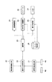
図3は、本発明の一実施の形態に係る携帯型情報機器の機能ブロック図である。
【0023】
同図に示すように、本実施の形態の携帯型情報機器は、電話着信検出部20、接続状態検出部21、通知方法決定部22、通知部23、音声出力制御部24、表示制御部25、スピーカ26、LCD27、データ格納部28及び振動制御部29を有している。
【0024】
電話着信検出部20は、自己宛の電話の着信を検出する。
【0025】
接続状態検出部21は、クレードル11の端子12がどの端子4a,4bに接続されているかを検出するものである。すなわち、端子4aにクレードル11の端子12が接続されている場合には、PDA1が図4に示すように、LCD2が前面側になるように載置された状態であることが検出され、端子4bにクレードル11の端子12が接続されている場合には、PDA1が図5に示すように、LCD1が奥になるように配置された状態であることが検出される。
【0026】
通知方法決定部22は、電話着信検出部20によって電話の着信が検出された場合に、接続状態検出部21によって検出された接続状態に基づいて、ユーザへの通知方法を決定するものである。
【0027】
通知部23は、通知方法決定部22によって決定された通知方法を音声出力制御部24及び表示制御部25に通知する。
【0028】
音声出力制御部24は、通知部23によって通知された通知方法にしたがって、データ格納部28に格納された音声データを再生し、スピーカ26から音声を出力する。
【0029】
表示制御部25は、通知部23によって通知された通知方法にしたがって、データ格納部28に格納された表示データをLCD27に表示する。
【0030】
データ格納部28は、音声出力制御部24によって使用される音声データ及び表示制御部25によって使用される表示データを格納する。
【0031】
振動制御部29は、通知部23によって通知された通知方法にしたがって、PDA自体の振動制御を行なうものである。
【0032】
次に、本実施の形態に係るPDAの動作について、図6のフローチャートを参照して説明する。
【0033】
まず、電話の着信があるか否かの判断が電話着信検出部20によって行なわれ(S1)、電話の着信があると判断された場合には、次に、接続状態検出部21によって接続状態の検出が行なわれる(S2)。
【0034】
そして、接続状態検出部21によって検出された接続状態が、端子4aにクレードルの端子が接続されてい場合には、LCDにメッセージを表示し、スピーカ26から音声を出力する(S4)。
【0035】
具体的には、通知方法決定部22によって、LCDにメッセージを表示し、音声を出力する旨の通知方法が決定され、この決定された通知方法が、通知部23によって音声出力制御部24及び表示制御部25に通知される。そして、音声出力制御部24は、データ格納部28に格納された音声データを再生して、スピーカ26から出力する。また、表示制御部25は、データ格納部28に格納された表示データに基づいて、LCD27にメッセージの表示を行なう。
【0036】
一方、S3において、端子4aにクレードルの端子が接続されていないと判断された場合には、次に、端子4bにクレードルの端子が接続されているか否かの判断が行なわれる(S5)。
【0037】
S5において、端子4bにクレードルの端子が接続されていると判断された場合には、電話の着信を無視する(S6)。すなわち、この場合には、PDAのLCDを後ろ向きにしてクレードルに装着されている場合である。ユーザは、例えば、就寝前に、このような状態でPDAをクレードルに装着することによって、睡眠を妨げられないですむ。
【0038】
一方、S5において、端子4bにクレードルの端子が接続されていないと判断された場合、すなわち、PDAがクレードルに装着されていない場合には、LCDにメッセージを表示、スピーカら音声を出力、及びPDAのバイブレーションを行なう。
【0039】
具体的には、通知方法決定部22によって、LCDにメッセージを表示し、音声を出力する旨の通知方法が決定され、この決定された通知方法が、通知部23によって音声出力制御部24及び表示制御部25に通知される。そして、音声出力制御部24は、データ格納部28に格納された音声データを再生して、スピーカ26から出力する。また、表示制御部25は、データ格納部28に格納された表示データに基づいて、LCD27にメッセージの表示を行なう。さらに、振動制御部29は、通知部23によって通知された通知方法に従って、PDAのバイブレーションを行なう。
【0040】
したがって、本実施の形態の携帯型情報機器によれば、クレードルへの装着状態によって、ユーザに知らせるべき事項(例えば、電話の着信、メールの受信、スケジュールプログラムの設定時刻アラームなど)の通知方法を変えることができるので、ユーザの使用状態において適切に通知を行なうことができる。
【0041】
なお、上述の実施の形態においては、電話を着信した場合についての通知方法について説明したが、これに限られるものではない。すなわち、ユーザに知らせるべき事項であれば良く、例えば、スケジュール管理用プログラムの設定時刻アラーム、メールの受信などであってもよい。
【0042】
また、上述の実施の形態においては、PDAに複数の端子を設け、これら端子へのクレードルの端子の接続状態に基づいて、ユーザへの通知方法を変える場合について説明したが、接続状態の判断方法は、これに限られるものではない。
【0043】
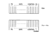
例えば、PDA側にも1つの端子、クレードルにも1つの端子を設け、その端子の配線構造を図7に示すような形態にしておく。具体的には、図7に示すように、PDA側の端子には、両側に電源線を設け、クレードル側の端子には、電源線及びダミーラインを設ける。このような配線構造を採用することにより、クレードルの取り付け状態を、電源線のバイアスを観察することにより、判断することができる。
【0044】
なお、図7に示すような構造を採用した場合、PDA側のデータ線及び制御線は、装着状態によって内部的に切り替えられる。すなわち、図7に示した状態がPDAのLCDを表向きに装着した場合を示しているとすると、PDAのLCDを裏面に向けて装着した場合には、クレードルの制御線に対応する配線が制御線になり、クレードルのデータ線に該当する配線がデータ線となるようにPDAの内部において配線の切り替えが行なわれる。このような構成を採用することにより、PDAが1つの端子しか有しない場合であっても、装着状態を認識することができるとともに、PDAのデータ線及び制御線とクレードルのデータ線及び制御線との整合性もとれる。
【0045】
さらに、本実施の形態においては、PDAを垂直に立てる場合について説明したが、PDAを水平に倒した状態でクレードルに収容する場合についても、その装着状態を判別することが可能である。この場合、例えば、クレードル背面に検出スイッチを設け、この検出スイッチがオンになった場合にはクレードルのLCDが表面を向いて装着されていると判断し、検出スイッチがオフの場合には、PDAが裏向きに装着されていると判断することができる。
【0046】
すなわち、本実施の形態においては、PDAのクレードルへの装着状態の検出方法は種々考えられる。
【0047】
なお、本願発明は、上記各実施形態に限定されるものでなく、実施段階ではその要旨を逸脱しない範囲で種々に変形することが可能である。また、各実施形態は可能な限り適宜組み合わせて実施してもよく、その場合組み合わされた効果が得られる。さらに、上記各実施形態には種々の段階の発明が含まれており、開示される複数の構成要件における適宜な組み合わせにより種々の発明が抽出され得る。例えば実施形態に示される全構成要件から幾つかの構成要件が省略されることで発明が抽出された場合には、その抽出された発明を実施する場合には省略部分が周知慣用技術で適宜補われるものである。
【0048】
【発明の効果】
以上詳記したように、本発明によれば、収容部に接続する状態に応じて、ユーザが携帯型情報機器の外部から通知されたイベント情報の発生を無視することを設定している場合、携帯型情報機器は、当該イベント情報の発生をユーザに通知しないことにより、就寝中の着信などによってユーザが睡眠を妨げられることがない。
【図面の簡単な説明】
【図1】本発明の一実施の形態に係るPDAの斜視図である。
【図2】クレードルを示す図である。
【図3】本発明の一実施の形態に係る携帯型情報機器の機能ブロック図である。
【図4】PDAのクレードルへの装着状態を示す図である。
【図5】PDAのクレードルへの装着状態を示す図である。
【図6】本実施の形態に係るPDAの動作について説明するためのフローチャートである。
【図7】クレードルの端子と、PDAの端子との配線構造を示す図である。
【図8】クレードルの端子と、PDAの端子との配線構造を示す図である。
【符号の説明】
1…PDA、
2…LCD,
3…キー入力部、
4a,4b…PDAの端子、
11…クレードル、
11a…垂直版、
11b…底面板、
12…クレードルの端子、
13…電源線、
14…データ線、
20…電話着信検出部、
21…接続状態検出部、
22…通知方法決定部、
23…通知部、
24…音声出力制御部、
25…表示制御部、
26…スピーカ、
27…LCD、
28…データ格納部、
29…振動制御部。[0001]
BACKGROUND OF THE INVENTION
The present invention relates to a portable information device such as a PDA or a mobile phone, and an information notification method in the portable information device.
[0002]
[Prior art]
In recent years, mobile phones have been widely used. However, in this mobile phone, incoming call control is changed depending on whether or not it is attached to a charger. Specifically, for example, when the mobile phone is attached to the charger, the incoming call is notified by sound and message, and when the mobile phone is not attached to the charger, the incoming call is sent to the mobile phone itself. We inform by vibrating.
[0003]
On the other hand, JP-A-5-167658 discloses a lighting control device for an indicator lamp in a mobile device.
[0004]
This lighting control device suppresses the consumption of the built-in rechargeable battery as much as possible by turning on the indicator light only when the surroundings are dark when the mobile device is picked up from the cradle. It is what.
[0005]
[Problems to be solved by the invention]
However, in the above mobile phone incoming call control, the control method is changed depending on whether or not the mobile phone is attached to the charger. However, when the mobile phone is attached to the charger, the incoming call notification method is used. Cannot be changed. Therefore, for example, even when a mobile phone is attached to a charger, there is a problem that it is not possible to cope with a case where it is not desired to be notified by voice at night.
[0006]
Similarly, in the indicator lighting control device for a mobile device disclosed in Japanese Patent Laid-Open No. 5-167658, when the mobile device is mounted on the cradle, the notification method of the incoming call cannot be changed. was there.
[0007]
The present invention has been made in view of the above circumstances, and an object thereof is to provide a portable information device capable of ignoring the occurrence of event information notified from the outside in accordance with the state of connection to a storage unit. And
[0008]
[Means for Solving the Problems]
Therefore, first, in order to achieve the above object, the first invention of the present invention has a connection terminal having a power supply line, a data line and a control line, and transmits data from the portable information device to the data line and the control line. A portable information device connected to a container that can be transferred via a connection terminal of the portable information device having a power line, a data line, and a control line, and a power line of the connection terminal of the portable information device. A means for detecting a connection state to the storage unit according to a bias state, and a user's portable type according to the detected connection state to the storage unit accompanying the occurrence of event information notified from outside Means for determining the usage status of the information device, and when it is set to ignore the occurrence of the event information according to the determined usage status, the portable information device generates the event information. User Portable information device, characterized in that it does not signal a.
The second aspect of the present invention, a power supply line, a connection terminal having a data and control lines, the data from the portable information equipment and the data line and can be transferred accommodating portion through a control line A connection terminal of a portable information device having a power line, a data line, and a control line; and means for detecting a connection state to the accommodating portion according to a bias state of the power line of the connection terminal of the portable information device. A portable information device having means for determining a use status of the user's portable information device in accordance with the detected connection state to the accommodation unit accompanying the occurrence of event information notified from outside And the portable information device does not notify the user of the occurrence of the event information when it is set to ignore the occurrence of the event information in accordance with the determined use situation. Type information system , It is.
[0016]
DETAILED DESCRIPTION OF THE INVENTION
Hereinafter, PDAs (Personal Digital Assistants) according to embodiments of the present invention will be described with reference to the drawings.
[0017]
FIG. 1 is a perspective view of a PDA according to an embodiment of the present invention.
[0018]
As shown in the figure, an LCD (Liquid Crystal Display) 2 and a
[0019]
FIG. 2 is a diagram illustrating a cradle.
[0020]
As shown in the figure, the
[0021]
As shown in FIG. 8, the
[0022]
FIG. 3 is a functional block diagram of the portable information device according to the embodiment of the present invention.
[0023]
As shown in the figure, the portable information device of the present embodiment includes a telephone incoming
[0024]
The incoming
[0025]
The connection
[0026]
The notification
[0027]
The
[0028]
The audio
[0029]
The
[0030]
The
[0031]
The
[0032]
Next, the operation of the PDA according to the present embodiment will be described with reference to the flowchart of FIG.
[0033]
First, whether or not there is an incoming call is determined by the incoming call detection unit 20 (S1). If it is determined that there is an incoming call, then the connection
[0034]
When the connection state detected by the connection
[0035]
Specifically, a notification method for displaying a message on the LCD and outputting a sound is determined by the notification
[0036]
On the other hand, when it is determined in S3 that the terminal of the cradle is not connected to the terminal 4a, it is next determined whether or not the terminal of the cradle is connected to the
[0037]
If it is determined in S5 that the cradle terminal is connected to the terminal 4b, the incoming call is ignored (S6). That is, in this case, the PDA is mounted on the cradle with the LCD facing backward. For example, the user is not obstructed to sleep by putting the PDA in the cradle in such a state before going to bed.
[0038]
On the other hand, if it is determined in S5 that the terminal of the cradle is not connected to the terminal 4b, that is, if the PDA is not attached to the cradle, a message is displayed on the LCD, the sound is output from the speaker, and the PDA Vibrate.
[0039]
Specifically, a notification method for displaying a message on the LCD and outputting a sound is determined by the notification
[0040]
Therefore, according to the portable information device of the present embodiment, there is provided a notification method of matters to be notified to the user (for example, incoming call, reception of mail, schedule program setting time alarm, etc.) depending on the mounting state in the cradle. Since it can be changed, it is possible to appropriately notify in the usage state of the user.
[0041]
In the above-described embodiment, the notification method when a call is received has been described. However, the present invention is not limited to this. In other words, it may be anything that should be notified to the user, and may be, for example, a set time alarm of a schedule management program, reception of mail, or the like.
[0042]
In the above-described embodiment, a case has been described in which a PDA is provided with a plurality of terminals and the method of notifying the user is changed based on the connection state of the terminals of the cradle to these terminals. Is not limited to this.
[0043]
For example, one terminal is provided on the PDA side and one terminal is provided on the cradle, and the wiring structure of the terminals is configured as shown in FIG. Specifically, as shown in FIG. 7, the PDA side terminal is provided with power supply lines on both sides, and the cradle side terminal is provided with power supply lines and dummy lines. By adopting such a wiring structure, it is possible to determine the attachment state of the cradle by observing the bias of the power supply line.
[0044]
When the structure shown in FIG. 7 is adopted, the data line and the control line on the PDA side are switched internally depending on the mounting state. That is, assuming that the state shown in FIG. 7 shows a case where the LCD of the PDA is mounted face up, when the LCD of the PDA is mounted facing back, the wiring corresponding to the control line of the cradle is connected to the control line. Thus, the wiring is switched inside the PDA so that the wiring corresponding to the data line of the cradle becomes the data line. By adopting such a configuration, even when the PDA has only one terminal, it is possible to recognize the mounting state, and the data line and control line of the PDA and the data line and control line of the cradle Consistency can be obtained.
[0045]
Furthermore, in the present embodiment, the case where the PDA is set up vertically has been described. However, even when the PDA is housed in the cradle in a state where the PDA is tilted horizontally, the mounting state can be determined. In this case, for example, a detection switch is provided on the back of the cradle, and when the detection switch is turned on, it is determined that the LCD of the cradle is mounted facing the front. When the detection switch is off, the PDA It can be determined that is mounted face down.
[0046]
That is, in the present embodiment, various methods for detecting the mounting state of the PDA in the cradle are conceivable.
[0047]
Note that the present invention is not limited to the above-described embodiments, and various modifications can be made without departing from the scope of the invention at the stage of implementation. In addition, the embodiments may be appropriately combined as much as possible, and in that case, the combined effect is obtained. Furthermore, the above embodiments include inventions at various stages, and various inventions can be extracted by appropriately combining a plurality of disclosed constituent elements. For example, when an invention is extracted by omitting some constituent elements from all the constituent elements shown in the embodiment, when the extracted invention is implemented, the omitted part is appropriately supplemented by a well-known common technique. It is what is said.
[0048]
【The invention's effect】
As described in detail above, according to the present invention, when the user is set to ignore the occurrence of event information notified from the outside of the portable information device, according to the state of connection to the storage unit , By not notifying the user of the occurrence of the event information, the portable information device does not prevent the user from sleeping due to an incoming call while sleeping.
[Brief description of the drawings]
FIG. 1 is a perspective view of a PDA according to an embodiment of the present invention.
FIG. 2 is a view showing a cradle.
FIG. 3 is a functional block diagram of a portable information device according to an embodiment of the present invention.
FIG. 4 is a diagram showing a state in which a PDA is mounted on a cradle.
FIG. 5 is a view showing a state where the PDA is mounted on the cradle.
FIG. 6 is a flowchart for explaining the operation of the PDA according to the present embodiment.
FIG. 7 is a diagram illustrating a wiring structure between a cradle terminal and a PDA terminal;
FIG. 8 is a diagram showing a wiring structure between a cradle terminal and a PDA terminal;
[Explanation of symbols]
1 ... PDA,
2 ... LCD,
3 ... Key input part,
4a, 4b ... PDA terminals,
11 ... Cradle,
11a ... vertical version,
11b ... bottom plate,
12 ... Cradle terminal,
13 ... Power line,
14 ... data line,
20 ... Call incoming detection unit,
21 ... Connection state detection unit,
22 ... Notification method determining unit,
23 ... notification section,
24. Audio output control unit,
25. Display control unit,
26 ... Speaker,
27 ... LCD,
28: Data storage unit,
29: Vibration control unit.
Claims (6)
電源線、データ線及び制御線を有する携帯型情報機器の接続端子と、
前記携帯型情報機器の接続端子の電源線のバイアス状態に応じて、前記収容部への接続状態を検知する手段と、
外部から通知されたイベント情報の発生に伴ない、前記検知された収容部への接続状態に応じて、ユーザの携帯型情報機器の使用状況を判断する手段とを具備し、
前記判断された使用状況に従い、前記イベント情報の発生を無視することを設定している場合、前記携帯型情報機器は前記イベント情報の発生をユーザに通知しないことを特徴とする携帯型情報機器。In a portable information device that has a connection terminal having a power line, a data line, and a control line, and is connected to a storage unit capable of transferring data from the portable information device via the data line and the control line,
A connection terminal of a portable information device having a power line, a data line and a control line;
Means for detecting a connection state to the accommodating portion according to a bias state of a power supply line of a connection terminal of the portable information device;
Along with the occurrence of event information notified from the outside, according to the detected connection state to the accommodation unit , comprising means for determining the usage status of the user's portable information device,
The portable information device does not notify the user of the occurrence of the event information when it is set to ignore the occurrence of the event information according to the determined use state.
電源線、データ線及び制御線を有する携帯型情報機器の接続端子と、前記携帯型情報機器の接続端子の電源線のバイアス状態に応じて、前記収容部への接続状態を検知する手段と、外部から通知されたイベント情報の発生に伴ない、前記検知された収容部への接続状態に応じて、ユーザの携帯型情報機器の使用状況を判断する手段とを有する携帯型情報機器と
を具備し、
前記携帯型情報機器は、前記判断された使用状況に従い、前記イベント情報の発生を無視することを設定している場合、前記イベント情報の発生をユーザに通知しないことを特徴とする携帯型情報システム。A storage unit having a connection terminal having a power line, a data line and a control line, and capable of transferring data from the portable information device via the data line and the control line
A connection terminal of a portable information device having a power line, a data line, and a control line; and a means for detecting a connection state to the accommodating portion according to a bias state of the power line of the connection terminal of the portable information device; A portable information device having means for determining the use status of the user's portable information device in accordance with the detected connection state to the accommodation unit accompanying the occurrence of event information notified from the outside And
The portable information device does not notify the user of the occurrence of the event information when the portable information device is set to ignore the occurrence of the event information according to the determined use situation. .
Priority Applications (2)
| Application Number | Priority Date | Filing Date | Title |
|---|---|---|---|
| JP2001074715A JP3769202B2 (en) | 2001-03-15 | 2001-03-15 | Portable information device and information notification method in portable information device |
| US10/055,929 US6882866B2 (en) | 2001-03-15 | 2002-01-28 | Portable information apparatus and information notification method for the same |
Applications Claiming Priority (1)
| Application Number | Priority Date | Filing Date | Title |
|---|---|---|---|
| JP2001074715A JP3769202B2 (en) | 2001-03-15 | 2001-03-15 | Portable information device and information notification method in portable information device |
Publications (2)
| Publication Number | Publication Date |
|---|---|
| JP2002281127A JP2002281127A (en) | 2002-09-27 |
| JP3769202B2 true JP3769202B2 (en) | 2006-04-19 |
Family
ID=18931926
Family Applications (1)
| Application Number | Title | Priority Date | Filing Date |
|---|---|---|---|
| JP2001074715A Expired - Fee Related JP3769202B2 (en) | 2001-03-15 | 2001-03-15 | Portable information device and information notification method in portable information device |
Country Status (2)
| Country | Link |
|---|---|
| US (1) | US6882866B2 (en) |
| JP (1) | JP3769202B2 (en) |
Families Citing this family (14)
| Publication number | Priority date | Publication date | Assignee | Title |
|---|---|---|---|---|
| JP2002359761A (en) * | 2001-05-31 | 2002-12-13 | Asahi Optical Co Ltd | Cradle for digital camera |
| US6812971B2 (en) * | 2001-09-11 | 2004-11-02 | Olympus Optical Co., Ltd. | Electronic apparatus, stand and electronic apparatus stand system |
| JP3535495B2 (en) * | 2001-12-26 | 2004-06-07 | 株式会社東芝 | Cradle-mounted digital camera, control method thereof, and cradle-mounted digital camera system |
| US6920337B2 (en) * | 2002-03-01 | 2005-07-19 | Hewlett-Packard Development Company, L.P. | Apparatus, system, and method for wireless notifications |
| KR100919978B1 (en) * | 2002-09-26 | 2009-10-05 | 삼성디지털이미징 주식회사 | Digital camera which displays communication state, and control method thereof |
| KR100503479B1 (en) * | 2003-01-24 | 2005-07-28 | 삼성전자주식회사 | a cradle of portable terminal and locking method of portable terminal using thereof |
| US7881283B2 (en) * | 2005-07-13 | 2011-02-01 | Research In Motion Limited | Customizability of event notification on telephony-enabled devices |
| US8351447B2 (en) * | 2007-04-20 | 2013-01-08 | Sony Corporation | Data communication system, cradle apparatus, server apparatus, data communication method and data communication program |
| JP5136170B2 (en) * | 2007-04-20 | 2013-02-06 | ソニー株式会社 | Data communication system, portable electronic device, server apparatus, and data communication method |
| US8624809B2 (en) | 2007-11-29 | 2014-01-07 | Apple Inc. | Communication using light-emitting device |
| US8493226B2 (en) | 2010-08-30 | 2013-07-23 | Brian Tedesco | Battery charger loss prevention adaptor having a notification module |
| US20150057952A1 (en) * | 2013-08-26 | 2015-02-26 | General Electric Company | Modular inspection system |
| JP6278123B2 (en) | 2014-08-29 | 2018-02-14 | 富士通株式会社 | Electronic devices and electronic components |
| USD971832S1 (en) | 2020-10-09 | 2022-12-06 | ACCO Brands Corporation | Combined electronic device charger and stand |
Family Cites Families (14)
| Publication number | Priority date | Publication date | Assignee | Title |
|---|---|---|---|---|
| JPH0636537B2 (en) | 1989-12-29 | 1994-05-11 | 日本無線株式会社 | Cordless phone system |
| JPH05167658A (en) | 1991-12-13 | 1993-07-02 | Sharp Corp | Lighting controller for display light in mobile set |
| US6324412B1 (en) * | 1994-06-17 | 2001-11-27 | Nokia Mobile Phones, Ltd. | Telephone and module having a pin for providing temperature information and generating a silent alarm |
| JPH08116351A (en) | 1994-10-18 | 1996-05-07 | Matsushita Electric Ind Co Ltd | External equipment connection recognizing device in portable telephone set |
| JPH0951578A (en) * | 1995-08-04 | 1997-02-18 | Uniden Corp | Cordless telephone device |
| JPH10136116A (en) | 1996-10-25 | 1998-05-22 | Oki Electric Ind Co Ltd | Slave set for cordless telephone set in common use with personal computer communication |
| JP3186643B2 (en) * | 1997-05-08 | 2001-07-11 | 日本電気株式会社 | Wireless device comprising a charger and a charger and a portable wireless device |
| JPH11225191A (en) | 1998-02-06 | 1999-08-17 | Brother Ind Ltd | Communications equipment and storage medium |
| JP2994317B2 (en) | 1998-02-09 | 1999-12-27 | 静岡日本電気株式会社 | Telephone and telephone control method |
| JPH11266319A (en) | 1998-03-17 | 1999-09-28 | Toshiba Corp | Communication terminal |
| JP4194172B2 (en) | 1998-05-18 | 2008-12-10 | キヤノン株式会社 | Image display device and inter-device communication method |
| JP3556489B2 (en) | 1998-11-30 | 2004-08-18 | 京セラ株式会社 | Charger |
| JP2000307757A (en) | 1999-04-20 | 2000-11-02 | Fujitsu General Ltd | Communication apparatus |
| US6373229B1 (en) * | 2001-03-23 | 2002-04-16 | Lucent Technologies Inc. | Battery charging system for portable electronic devices |
-
2001
- 2001-03-15 JP JP2001074715A patent/JP3769202B2/en not_active Expired - Fee Related
-
2002
- 2002-01-28 US US10/055,929 patent/US6882866B2/en not_active Expired - Fee Related
Also Published As
| Publication number | Publication date |
|---|---|
| US6882866B2 (en) | 2005-04-19 |
| JP2002281127A (en) | 2002-09-27 |
| US20020132639A1 (en) | 2002-09-19 |
Similar Documents
| Publication | Publication Date | Title |
|---|---|---|
| JP3769202B2 (en) | Portable information device and information notification method in portable information device | |
| US7194248B2 (en) | Apparatus and method for performing power saving control of mobile terminal | |
| US9094932B2 (en) | Mobile electronic device | |
| KR101533099B1 (en) | Mobile terminal and operation control method thereof | |
| JP2000138762A (en) | Device and method for calling | |
| KR101488391B1 (en) | Mobile terminal and control method thereof | |
| KR100877473B1 (en) | Terminal apparatus and medium for recording a control program thereof | |
| CN101827169A (en) | Mobile terminal and method for displaying data in mobile terminal | |
| WO2007114066A1 (en) | Portable terminal and function operation control method | |
| US8055245B2 (en) | Mobile device with fake communication mode | |
| US8280411B2 (en) | Communication terminal device and control program thereof | |
| US20040196985A1 (en) | Electronic apparatus having a detachable speaker unit | |
| JP2001197197A (en) | Portable telephone set and storage medium | |
| JPH10210550A (en) | Composite portable terminal equipment | |
| JP2001268183A (en) | Mobile phone with battery alarm function | |
| US20060121954A1 (en) | Power consumption management for the playback of multimedia messages | |
| JP4315210B2 (en) | Communication device | |
| JP3573998B2 (en) | Mobile phone equipment | |
| JP4032214B2 (en) | Mobile phone and power supply control method | |
| JP2003258942A (en) | Portable terminal | |
| JP3733904B2 (en) | Mobile phone device and control method thereof | |
| JP2001274898A (en) | Portable equipment | |
| JP5205331B2 (en) | Portable information terminal | |
| JP2002164963A (en) | Vibration type ringer notice unit for mobile phone | |
| JP2000224274A (en) | Portable telephone set |
Legal Events
| Date | Code | Title | Description |
|---|---|---|---|
| A131 | Notification of reasons for refusal |
Free format text: JAPANESE INTERMEDIATE CODE: A131 Effective date: 20040810 |
|
| A521 | Request for written amendment filed |
Free format text: JAPANESE INTERMEDIATE CODE: A523 Effective date: 20041007 |
|
| TRDD | Decision of grant or rejection written | ||
| A01 | Written decision to grant a patent or to grant a registration (utility model) |
Free format text: JAPANESE INTERMEDIATE CODE: A01 Effective date: 20060131 |
|
| A61 | First payment of annual fees (during grant procedure) |
Free format text: JAPANESE INTERMEDIATE CODE: A61 Effective date: 20060203 |
|
| LAPS | Cancellation because of no payment of annual fees |