JP3757925B2 - Graphic display control apparatus and graphic display control program - Google Patents
Graphic display control apparatus and graphic display control program Download PDFInfo
- Publication number
- JP3757925B2 JP3757925B2 JP2002287301A JP2002287301A JP3757925B2 JP 3757925 B2 JP3757925 B2 JP 3757925B2 JP 2002287301 A JP2002287301 A JP 2002287301A JP 2002287301 A JP2002287301 A JP 2002287301A JP 3757925 B2 JP3757925 B2 JP 3757925B2
- Authority
- JP
- Japan
- Prior art keywords
- geometric
- function
- graphic
- graph
- expression
- Prior art date
- Legal status (The legal status is an assumption and is not a legal conclusion. Google has not performed a legal analysis and makes no representation as to the accuracy of the status listed.)
- Expired - Fee Related
Links
Images


Landscapes
- Controls And Circuits For Display Device (AREA)
- Calculators And Similar Devices (AREA)
Description
【0001】
【発明の属する技術分野】
本発明は、図形表示制御装置及び図形表示制御プログラムに関する。
【0002】
【従来の技術】
従来から、幾何図形を描画する描画機能を備えた装置が知られている。例えば、方程式計算、行列演算、複素数演算等の計算機能や、財務計算機能、統計機能等の豊富な機能を備えた関数電卓において、上述した描画機能を備えた関数電卓(以下、「関数電卓」という。)が知られている。この関数電卓は、例えば、計算機能を利用した各種技術計算の演算結果をグラフ化して表示させることや図形の式を入力して図形を描画して表示させることができる。従って教育現場において数式等の文字データとグラフや図形の関係を勉強する為等に広く活用されている。
【0003】
また、上述したような関数電卓において、表示させたいグラフの概形を入力ペン等で手書き入力するとともに、当該グラフ上の座標を入力することにより、グラフ式を特定させて、当該グラフ式に基づく正確なグラフを表示させる機能を備えたものが知られている(例えば、特許文献1参照。)。
【0004】
【特許文献1】
特開平9−282476号公報
【0005】
【発明が解決しようとする課題】
しかし従来の関数電卓では、関数式や図形の式を入力してグラフ化したり、グラフ表示からグラフ式や図形を表示させるためには、その目的に応じて、それぞれ異なる一連の操作を必要としていた。従って従来の関数電卓を用いて、数式等の文字データとグラフや図形の関係を学習・分析する為には、それぞれの一連の操作を行う必要があり、関数電卓の操作を良く理解している必要があった。
【0006】
本発明は、上記した従来の事情に鑑みてなされたものであり、きわめて簡単な操作により数式等の文字データとそれに対応するグラフや図形等の関係を理解することができる図形表示制御装置を実現することを目的とする。
【0007】
【課題を解決するための手段】
以上の課題を解決するため、請求項1に記載の発明の図形表示制御装置は、グラフ図形を表示する図形画面 ( 図2のGW1 ) と関数式を表示する数式画面 ( 図2のCW1 ) とからなる表示部 ( 図3の50 ) を備える図形表示制御装置において、前記数式画面に表示された関数式を指定する関数式指定手段(図3のタブレット30、図9のA18、A20)と、この関数式指定手段により関数式が指定された後に、当該関数式の貼り付け先を指定する貼付先指定手段(図3のタブレット30、図9のA22、A24)と、この貼付先指定手段により前記図形画面が指定された場合に、前記関数式指定手段により指定された関数式に対応するグラフ図形を前記図形画面に描画するグラフ描画手段 ( 図3の10、図14のD278 ) と、このグラフ描画手段により描画されたグラフ図形に対応付けて、前記関数式指定手段により指定された関数式を記憶する対応付関数式記憶手段(図3の82〜84、図5、図6、図7;図14のD290)と、前記図形画面に表示されたグラフ図形に対して変更操作を行う図形変更操作手段(図2の30、図9のA26、A28)と、この図形変更操作手段により変更されたグラフ図形に対応付けて、前記対応付関数式記憶手段に記憶されている関数式の前記数式画面の表示を、前記変更操作されたグラフ図形に応じて変更するように表示制御する変更表示制御手段(図3の10、図9のA32)と、を備えることを特徴としている。
【0009】
この請求項1に記載の発明によれば、数式画面に表示された関数式を指定した後に、関数式の貼り付け先を図形画面に指定すると、指定された関数式に対応するグラフ図形が図形画面に描画されるとともに、このグラフ図形に対応付けて、前記指定された関数式が記憶され、図形変更操作手段により図形画面に表示されたグラフ図形に対して変更操作を行うと、変更されたグラフ図形に対応付けて記憶されている関数式の表示が、前記変更操作されたグラフ図形に応じて変更されるようにしたので、きわめて簡単な操作で数式画面に表示された関数式に対応するグラフ図形が図形画面に表示されて対応付けされ、グラフ図形を変更操作するだけで対応する関数式がグラフ図形に応じて変更される。従って、きわめて簡単な操作によりグラフ図形とそれに対応する数式の関係を学ぶことができる。
【0010】
また、請求項2に記載の発明は、請求項1に記載の図形表示制御装置において、前記数式画面に表示された関数式の変更操作を行う数式変更操作手段(図2の20、図9のA34、A36)と、この数式変更操作手段により変更入力された関数式に対応付けて、記憶されているグラフ図形の表示を、前記変更入力された関数式に応じて変更して描画する変更描画手段(図3の10、図9のA40)と、を備えることを特徴としている。
【0011】
この請求項2に記載の発明によれば、数式変更操作手段により数式画面に表示された関数式の変更操作を行うと、この変更された関数式に対応付けて記憶されているグラフ図形の表示が、変更操作された関数式に応じて変更して描画されるので、例えば関数式のパラメータ等を任意に変更操作して、対応するグラフ図形の変化を視覚的に確認でき、きわめて簡単な操作により数式等とそれに対応するグラフ図形の関係を学ぶことができる。
【0012】
請求項3に記載の図形表示制御装置は、請求項1又は2に記載の図形表示制御装置において、前記対応付関数式記憶手段は、各グラフ図形に対応付けてそれぞれ関数式を記憶し(図5、図6、図7)、前記変更表示制御手段は、前記数式画面に表示された複数の関数式のうち、前記変更されたグラフ図形に対応付けて、前記対応付関数式記憶手段に記憶された関数式を変更するように制御する(図9のA30〜A32)ことを特徴とすることを特徴としている。
【0013】
この請求項3に記載の発明によれば、対応付関数式記憶手段には、各グラフ図形に対応付けてそれぞれ関数式が記憶されており、前記数式画面に表示された複数の関数式のうち、ユーザにより変更されたグラフ図形に対応付けられて前記対応付関数式記憶手段に記憶された関数式が変更されるので、例えば複数組の関数式とグラフ式が、それぞれ数式画面と図形画面に表示されていても、ユーザが変更したグラフ図形に対応する関数式が適切に変更されて表示される。例えば比較の為に、関数式やグラフ図形を複数組表示させて、所望のグラフ図形を変更すれば、対応する関数式のみ適切に変更され、比較しながら、グラフ図形と関数式の関係を学ぶことができる。
【0014】
そして、請求項4に記載の発明は、請求項1〜3の何れか一項に記載の図形表示制御装置において、前記対応付関数式記憶手段により対応付けて記憶されているグラフ図形又は関数式関数式とに対して、対応付けがされていることを示す識別表示を行う対応付け識別表示手段(図13のD21、図16)を備えることを特徴とことを特徴としている。
【0015】
この請求項4に記載の発明によれば、対応付けて記憶されているグラフ図形又は関数式関数式が識別表示により確認できるので、表示されたグラフ図形や関数式が対応付けされているかどうかを、表示上で直ちに確認できる。
【0018】
【発明の実施の形態】
以下、図1〜図25を参照して、本発明に係る図形表示制御装置を関数電卓に適用した場合の実施の形態について詳細に説明する。
【0019】
図1に、本発明を適用した関数電卓1の概観図の一例を示す。同図に示すように、関数電卓1は、ディスプレイ3、各種キー群5、入力ペン7を備えて構成されている。各種キー群5を構成するキーにはそれぞれ固有の機能が割り当てられており、ユーザは、これらのキーを押下して関数電卓1を操作する。さらに、ディスプレイ3には後述するタブレット(タッチパネル)30が一体的に構成されており、ユーザは、入力ペン7を使用したディスプレイ3上のタッチ操作により入力することも可能である。
【0020】
〔第1の実施の形態〕
先ず、本発明を適用した関数電卓の第1の実施の形態について説明する。尚、以下においては、本発明を、幾何図形描画機能を実現するための幾何アプリケーションプログラム(以下、適宜「幾何アプリケーション」という。)及び計算機能を実現するための計算アプリケーションプログラム(以下、適宜「計算アプリケーション」という。)を搭載した関数電卓に適用した場合を例にとって説明する。
【0021】
本第1の実施の形態は、幾何アプリケーションの画面(以下、「幾何ウィンドウ」という。)に表示される一の幾何図形と計算アプリケーションの画面(以下、「計算ウィンドウ」という。)に表示される一の計算データとの間に、双方を関連付けるリンクが形成されている際に、何れか一方の変更操作に応じて他方を自動的に変更して表示更新するものである。
【0022】
また、第1の実施の形態において、関数電卓1は、幾何ウィンドウと計算ウィンドウの内、何れか一方の画面の表示内容が選択されてコピー操作がなされ、他方の画面が指定されてペースト操作がなされた際に、当該選択された一方の画面の表示内容を、他方の画面の表示形態に応じて表示制御するコピーアンドペースト機能を備え、コピーアンドペースト操作が入力された際に、当該一方の画面で選択された表示内容と、他方の画面に表示される内容とを関連付けるリンクを自動的に形成する。
【0023】
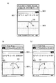
図2に、本発明を適用した第1の実施の形態における関数電卓1の表示画面の画面遷移例を示す。同図において、表示画面上には、計算ウィンドウCW1と幾何ウィンドウGW1とが表示されている。ユーザは、同図に示す計算ウィンドウCW1において、方程式計算、行列演算、複素数演算等の各種計算処理を行わせることができる。また、ユーザは、幾何ウィンドウGW1において、描画したい図形の幾何種別を指定するとともに、当該幾何図形の特定点座標を指定(幾何種別が関数グラフの場合には関数式を入力)することにより、幾何ウィンドウGW1に、該当する幾何図形オブジェクトを表示させることができる。
【0024】
また、幾何ウィンドウGW1に表示される幾何図形オブジェクトは、入力ペン等により選択して、当該幾何図形オブジェクトを回転させたり、平行移動させることができる。
【0025】
さらに、リンクモードを設定することにより、幾何ウィンドウGW1上に表示される任意の幾何図形オブジェクトと、計算ウィンドウCW1上に表示される任意の計算データとの間に、双方を関連付けるリンクを形成させることができる。
【0026】
ここで、幾何図形とは、点、線(線分、直線を含む)、ベクトル、円(円弧を含む)、多角形、関数グラフ等の線図として表せるもののことである。また、オブジェクトとは、描画(表示)された幾何図形の単位のことである。例えば、円の幾何図形が描画されている場合には、その描画されている線図(円)のことを円オブジェクトという。円と直線とが描画されている場合には、円に係る線図の部分を円オブジェクトといい、直線に係る線図の部分を直線オブジェクトという。
【0027】
関数電卓1において、幾何アプリケーション及び計算アプリケーションを起動し、上述したように幾何ウィンドウGW1と計算ウィンドウCW1とを表示画面上に表示させた状態で、例えば、幾何ウィンドウGW1において、円の描画指示を入力するとともに点A,Bを入力ペン等で指示すると、点Aを中心に、点Bを円周上の1点とする円オブジェクト100が描画される。
【0028】
ここで、例えば、円オブジェクト100を選択してコピー操作を入力し、幾何ウィンドウGW1を指定してペースト操作を入力すると、計算ウィンドウCW1のカーソル位置に、対応する円の方程式“x2+y2−4=0”が表示される。尚、計算ウィンドウCW1において、円の方程式“x2+y2−4=0”を入力するとともに、当該数式“x2+y2−4=0”を選択してコピー操作を入力し、幾何ウィンドウGW1を指定してペースト操作を入力すると、幾何ウィンドウGW1に、当該数式“x2+y2−4=0”に基づく円オブジェクト100が描画されるようになっている。
【0029】
ここで、コピーアンドペースト操作とは、画面上の所望のデータ(図形、画像又は文字列等)をポインティングデバイス(ペンやマウス等)で指定して、さらに、そのデータ又はそのデータの代替物を貼り付ける位置をポインティングデバイス(ペンやマウス等)で指定する操作である。この操作は、例えば、ペンで画面上の所望のデータを指定した後に、コピーコマンドを実行して、さらに、ペンで貼り付け先の位置を指定して、コピーコマンドを実行する操作により行われる。
【0030】
また、例えば、ペンで画面上の所望のデータにタッチして指定し、そのタッチを維持したまま移動する操作(以下ドラッグ操作という)と、ドラッグ操作に引き続き、所望のデータのタッチを維持した状態から、貼り付け先の位置でペンをアップさせる操作(この操作を以下ドロップ操作という)により実現可能である。
【0031】
尚、表示装置(例えば、図1に示すディスプレイ3)に入力ペン(例えば、図1に示す入力ペン7)を当接させるとともに、当該表示装置に当接させた入力ペンを表示装置上で摺動させる操作のことをドラッグ、入力ペンを表示装置から離す操作をドロップといい、この一連の操作をドラッグアンドドロップという。また、コピーアンドペースト操作は、コピー元の画面においてボタン等で提供されるコピーメニューを選択し、コピー先の画面でペーストメニューを選択することにより実現することとしてもよい。
【0032】
さて、コピーアンドペースト操作を入力すると、該当する幾何図形オブジェクトと計算データとの間に、双方を関連付けるリンクが自動的に形成される。図2(a)に示すように、計算ウィンドウCW1において、幾何図形オブジェクトと関連付けられた計算データの近傍に、リンクマークM1が表示される。
【0033】
この(a)に示す幾何ウィンドウGW1において、入力ペン等を用いて円オブジェクト100を選択し、例えば、移動操作を入力して(b)に示すように円オブジェクト100の表示位置を変更させると、計算ウィンドウCW1の計算データが、当該移動操作量に基づいて算出された円の方程式“x2+y2−6x+y+7=0”に変更される。また、この(b)に示す計算ウィンドウCW1において計算データ“x2+y2−6x+y+7=0”を“x2+y2−4x+2y−4=0”に変更すると、(c)に示すように、幾何ウィンドウGW1に描画される円オブジェクト100が当該変更操作に応じて変形される。
【0034】
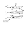
図3は、関数電卓1の機能構成例を示す図である。同図に示すように、関数電卓1は、CPU10、入力部20、タブレット30、位置検出回路40、通信部60、表示部50、ROM70、RAM80の各機能部を備えて構成される。
【0035】
CPU10は、入力される指示に応じて所定のプログラムに基づいた処理を実行し、各機能部への指示やデータの転送等を行い、関数電卓1を統括的に制御する。具体的には、CPU10は、入力部20又はタブレット30から入力される操作信号に応じてROM70に格納されたプログラムを読み出し、当該プログラムに従って処理を実行する。そして、処理結果をRAM80に保存するとともに、当該処理結果を表示するための表示信号を適宜表示部50に出力して、対応した表示情報を表示させる。
【0036】
入力部20は、数値や数式等の入力、機能選択等に必要なキー群を備えた入力装置であり、押下されたキーの押下信号等をCPU10に出力する。この入力部20におけるキー入力により、特に、幾何アプリケーション又は数式アプリケーションの起動指示、図形描画処理の実行、数式の入力、演算処理等の実行、処理の終了やモードの解除、各種ポインタやメニュー画面におけるカーソル等の移動、又は各種選択操作や当該選択操作の確定指示等の入力手段を実現する。尚、この入力部20は、図1に示すキー群5に相当するものである。
【0037】
また、関数電卓1は、入力装置として、タッチパネルであるタブレット30を備える。このタブレット30は、表示部50における位置を指示する入力ペン(図1に示す、入力ペン7に相当)等の装置と、指示された表示部50の位置を感知する装置とが組み合わされた入力装置であり、タブレット30に接続される位置検出回路40は、タブレット30により指示された位置座標を検出する。このタブレット30を使用すれば、表示部50における位置を細かく指定することができ、タブレット30を使用した表示部50のタッチ操作により、上述した入力部20における入力手段を実現することができる。
【0038】
特に、このタブレット30を使用したドラッグアンドドロップ操作により、幾何ウィンドウと計算ウィンドウの何れか一方の画面で指定したデータを他方の画面にコピーすることができる。
【0039】
通信部60は、ネットワークN1を介して接続される他の装置(例えば、サーバ90)と所定の情報を送受するための通信装置で構成される。CPU10は、この通信部60及びネットワークN1を介し、外部機器との通信を行うための制御を行う。
【0040】
具体的には、例えば、通信部60及びネットワークN1を介してサーバ90から受信したプログラムやデータ等をROM70やRAM80に格納するように構成することにより、ユーザは、サーバ90内に蓄積されるプログラムやデータ等を利用することができる。
【0041】
表示部50は、CPU10から入力される表示信号に基づいて表示部50を制御して各種画面を表示させるものであり、LCD(Liquid Crystal Display)等により構成される。尚、この表示部50は、図1に示すディスプレイ3に相当するものであり、タブレット30と一体的に形成されている。
【0042】
ROM70には、各種初期設定、ハードウェアの検査、又は必要なプログラムのロード等を行うための初期プログラムが格納される。CPU10は、関数電卓1の電源投入時においてこの初期プログラムを実行することにより、関数電卓1の動作環境を設定する。
【0043】
また、ROM70には、幾何アプリケーションプログラムや、計算アプリケーションプログラム等のアプリケーションプログラム、メニュー表示処理、各種設定処理等の関数電卓1の動作に係る各種処理プログラム、関数電卓1の備える種々の機能を実現するためのプログラム等が格納されるとともに、特に、メイン処理プログラム72が格納される。このメイン処理プログラム72は、データ入力処理プログラム72a、コピー/(又は)ドラッグ処理プログラム72b、及びペースト/ドロップ処理プログラム72cを有する。
【0044】
CPU10は、メイン処理プログラム72に従って処理を実行する。特に、CPU10は、ユーザによるデータ入力操作に応じてデータ入力処理プログラム72aの実行を開始し、データ入力処理を行う。また、CPU10は、ユーザによるコピー/ドラッグ操作に応じてコピー/ドラッグ処理プログラム72bの実行を開始し、コピー/ドラッグ処理を行う。そして、CPU10は、ユーザによるペースト/ドロップ操作に応じてペースト/ドロップ処理プログラム72cの実行を開始し、ペースト/ドロップ処理を行う。
【0045】
RAM80は、CPU10が実行する各種プログラムや、これらプログラムの実行に係るデータ等を一時的に保持するメモリ領域を備える。特に、幾何ウィンドウ上に描画される幾何データを保持する幾何ウィンドウデータ81と、計算ウィンドウ上に表示される計算データを保持する計算ウィンドウデータ82と、幾何ウィンドウに描画される関数グラフの関数式データを保持する関数式テーブル83と、幾何ウィンドウ上に表示された幾何図形オブジェクトと、計算ウィンドウ上に表示された計算データとのリンク情報を保持するリンクテーブル84と、コピー操作により指定されたデータを一時的に保持するためのコピーバッファ85とを備える。
【0046】
図4に、幾何ウィンドウデータ81の一例を示す。同図に示すように、幾何ウィンドウデータ81は、幾何図形IDと、幾何種別と、特定点座標とが対応付けられたデータテーブルである。CPU10は、幾何ウィンドウにおいて幾何図形の描画指示が入力された際に、指定された特定点座標に基づいて、該当する幾何図形オブジェクトを描画する。この際、CPU10は、当該幾何図形オブジェクトに固有の幾何図形IDを割り当てて、幾何図形IDと、幾何種別と、特定点座標とを対応付けて、幾何ウィンドウデータ81に格納する。
【0047】
即ち、この幾何ウィンドウデータ81において、幾何ウィンドウに描画されている関数グラフ以外の幾何図形の特定点座標を保持し、幾何アプリケーションは、幾何ウィンドウデータ81に格納される特定点座標に基づいて幾何図形を描画する。
【0048】
例えば、幾何種別が“直線”の場合には、幾何ウィンドウデータ81において、指定された2点の座標を、第1特定点座標及び第2特定点座標として保持する。幾何種別が“n角形”の場合には、指定されたn個の頂点座標を、第1〜第n特定点座標として保持する。幾何種別が“円”の場合には、指定された中心の座標を第1特定点座標、円周上の1点の座標を第2特定点座標として保持する。幾何種別が“楕円”の場合には、指定された中心座標を第1特定点座標、短半径を示す座標を第2特定点、長半径を示す座標を第3特定点として保持する。例えば、図4に示す幾何ウィンドウデータ81において、幾何図形ID“ID_G028”が割り当てられた円オブジェクトには、中心座標である第1特定点(0,0)と、円周上の1点の座標である第2特定点(2,0)が定義されている。
【0049】
また、CPU10は、幾何ウィンドウにおいて描画指示された幾何図形の幾何種別が関数グラフの場合は、指定された関数式に基づいて関数グラフオブジェクトを描画する。この際、特に、CPU10は、当該関数グラフオブジェクトに幾何図形IDを割り当てて幾何ウィンドウデータ81を更新するとともに、関数式テーブル83を更新する。
【0050】
図5に、関数式テーブル83の一例を示す。同図に示すように、関数式テーブル83は、幾何図形IDと関数式とが対応付けられたデータテーブルである。CPU10は、幾何ウィンドウにおいて関数グラフオブジェクトを描画した際に、当該関数グラフオブジェクトに割り当てられた幾何図形IDと、該当する関数式とを対応付けて関数式テーブル83に格納する。例えば、図5に示すように、関数式テーブル83には、図4に示して説明した幾何ウィンドウデータ81において幾何図形ID“ID_G030”が割り当てられた関数グラフオブジェクトの関数式“y=3x2+2”が、当該幾何図形ID“ID_G030”と対応付けられて格納されている。
【0051】
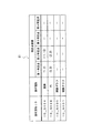
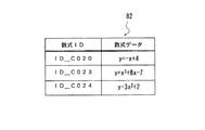
図6に、計算ウィンドウデータ82の一例を示す。同図に示すように、計算ウィンドウデータ82は、数式IDと、数式データとが対応付けられたデータテーブルである。CPU10は、計算ウィンドウにおいて計算データが入力された際に、当該入力された計算データに固有の数式IDを割り当てて、数式IDと、数式データとを対応付けて計算ウィンドウデータ82に格納する。
【0052】
また、CPU10は、リンク関係が設定されているか否かをリンクテーブル84を参照して判断する。
【0053】
図7は、リンクテーブル84の一例を示す図である。同図に示すように、リンクテーブル84は、幾何図形IDと数式IDとが対応付けられたデータテーブルである。CPU10は、コピーアンドペースト操作によって、幾何図形オブジェクトから計算データにコピーアンドペーストされた場合、又は、計算データから幾何図形オブジェクトにコピーアンドペーストされた場合には、幾何図形オブジェクトの幾何図形IDと、計算データの数式IDとを対応付けてリンクテーブル84に格納する。
【0054】
より具体的には、CPU10は、コピー操作の際に選択されたデータをコピーバッファ85内に一時的に保持する際に、当該コピーデータにリンクを形成するか否かを判断するための情報を対応付けて格納する。
【0055】
図8に、コピーバッファ85の一例を示す。同図に示すように、コピーバッファ85には、コピーデータが、計算リンクフラグと、幾何リンクフラグと対応付けて格納される。
【0056】
CPU10は、コピーバッファ85にコピーデータを格納する際に、リンクモードが設定されている場合であって、コピーデータが計算ウィンドウでコピー操作されたデータの場合には、計算リンクフラグを“ON”に設定し、コピーデータが幾何ウィンドウでコピー操作されたデータの場合には、幾何リンクフラグを“ON”に設定する。
【0057】
そして、CPU10は、例えば、幾何ウィンドウで選択された幾何図形オブジェクトを計算ウィンドウにコピーする際に、幾何リンクフラグに“ON”が設定されている場合にはリンクテーブル84を更新する。即ち、幾何アプリケーションから計算アプリケーションにコピーアンドペースト操作が入力された場合や、又は計算アプリケーションから幾何アプリケーションにコピーアンドペースト操作が入力された場合といった、異なるアプリケーション間でのコピーアンドペースト操作に応じて、該当する幾何図形オブジェクトと計算データとを相互に関連付けたリンクを形成する。
【0058】
次に、本発明を適用した第1の実施の形態における関数電卓1の動作について説明する。
【0059】
図9は、メイン処理の実行に係る関数電卓1の動作を示すフローチャートである。同図に示すように、CPU10は、入力部20又はタブレット30を介してユーザによるデータ入力操作を検知した場合には(ステップA10:YES)、データ入力処理を実行する(ステップA12)。
【0060】
また、CPU10は、ユーザによるリンクモード設定操作を検知した場合には(ステップA14:YES)、リンクモードを設定する(ステップA16)。
【0061】
また、CPU10は、ユーザによるコピー操作又はドラッグ操作を検知した場合には(ステップA18:YES)、コピー/ドラッグ処理を実行する(ステップA20)。
【0062】
また、CPU10は、ユーザによるペースト操作又はドラッグ操作を検知した場合には(ステップA22:YES)、ペースト/ドロップ処理を実行する(ステップA24)。
【0063】
また、CPU10は、幾何系ウィンドウ(例えば、幾何ウィンドウ)での幾何図形の変形操作を検知した場合には(ステップA26:YES)、変形操作に応じた図形変形処理を実行し(ステップA28)、幾何ウィンドウの表示を更新する。
【0064】
そして、CPU10は、変形した幾何図形オブジェクトがリンクテーブル84に登録されているか否かを判定する(ステップA30)。具体的には、変形した幾何図形オブジェクトに割り当てられた幾何図形IDがリンクテーブル84内に格納されているか否かで判定する。そして、CPU10は、当該変形した幾何図形がリンクテーブル84に登録されていると判定した場合には、対応する計算系ウィンドウの式・座標・行列の数値の変更処理を実行し(ステップA32)、計算ウィンドウの表示を更新する。
【0065】
また、CPU10は、計算系ウィンドウ(例えば、計算ウィンドウ)での計算データの変更操作を検知した場合には(ステップA34:YES)、変更操作に応じた式・座標・行列変更処理を実行し(ステップA36)、計算ウィンドウの表示を更新する。
【0066】
そして、CPU10は、変更した式・座標・行列がリンクテーブル84に登録されているか否かを判定する(ステップA38)。具体的には、変更した式・座標・行列に割り当てられた数式IDがリンクテーブル84内に格納されているか否かで判定する。そして、CPU10は、当該変更した式・座標・行列がリンクテーブル84に登録されていると判定した場合には、対応する幾何系ウィンドウの幾何図形オブジェクトの変形処理を実行し(ステップA40)、幾何ウィンドウの表示を更新する。
【0067】
そして、CPU10は、ユーザによる終了操作を検知した場合には(ステップA42:YES)、本処理を終了する。以下、ステップA12のデータ入力処理、ステップA20のコピー/ドラッグ処理、ステップA24のペースト/ドロップ処理の各処理について図10〜図14を参照して説明する。
【0068】
先ず、データ入力処理について説明する。図10は、データ入力処理の実行に係る関数電卓1の動作を示すフローチャートである。同図に示すように、CPU10は、テキストデータが入力された場合には(ステップB10:YES)、当該テキストデータが入力された指定ウィンドウのカーソル位置がテキスト入力可能か否かを判定する(ステップB12)。第1の実施の形態において、テキストデータが入力された場合とは、特に、計算ウィンドウに対して座標値、直線式、円/楕円の方程式、関数式等の各種数式データが入力された場合のことをいう。
【0069】
そして、CPU10は、カーソル位置へのテキスト入力が不可能な場合にはエラー処理に遷移して、例えば、表示部50にエラーメッセージを表示させて報知する。また、CPU10は、カーソル位置へのテキスト入力が可能な場合には、入力されたテキストデータを指定ウィンドウのカーソル位置に表示させる(ステップB14)。
【0070】
また、CPU10は、コマンドデータが入力された場合には(ステップB16:YES)、当該コマンドデータが入力された指定ウィンドウについて、指定コマンドに対応する処理を実行する(ステップB18)。第1の実施の形態において、コマンドデータが入力された場合とは、特に、幾何ウィンドウに対して各種幾何図形の描画を指示するコマンドが入力された場合のことをいう。
【0071】
そして、CPU10は、入力されたコマンドデータが関数グラフの描画・設定コマンドの場合には(ステップB20:YES)、関数式テーブル83に該当する関数式を格納して(ステップB22)、指定ウィンドウに描画・設定した関数グラフオブジェクトと、関数式テーブル83に格納した関数式とを対応付ける(ステップB24)。具体的には、描画・設定した関数グラフオブジェクトに対応する関数式と、当該関数式に割り当てられた幾何図形IDとを対応付けて関数式テーブル83に格納するとともに、指定ウィンドウに描画・設定した関数グラフオブジェクトに該当する幾何図形IDを対応付ける。
【0072】
また、CPU10は、ウィンドウを開く/閉じる指示が入力された場合には(ステップB26:YES)、指定ウィンドウを開く/閉じる処理を実行する(ステップB28)。また、CPU10は、その他の入力操作がなされた場合には、該当する他処理へ遷移して実行する。
【0073】
次に、コピー/ドラッグ処理について説明する。図11は、コピー/ドラッグ処理の実行に係る関数電卓1の動作を示すフローチャートである。同図に示すように、CPU10は、先ず、コピー/ドラッグ元のウィンドウの種類を検知する(ステップC10)。
【0074】
そして、CPU10は、コピー/ドラッグ元のウィンドウの種類がテキスト系ウィンドウ(例えば、計算ウィンドウ)の場合には(ステップC12:YES)、文字列の指定範囲を検知する(ステップC14)。そして、CPU10は、検知した指定範囲の文字列をコピーバッファ85に格納する(ステップC16)。さらに、CPU10は、リンクモードが設定されている場合には(ステップC18:YES)、コピーバッファ85の対応する計算リンクフラグを“ON”に設定して(ステップC20)、本処理を終了する。
【0075】
また、CPU10は、検知したコピー/ドラッグ元のウィンドウの種類が幾何系ウィンドウ(例えば、幾何ウィンドウ)の場合には(ステップC22:YES)、先ず、指定された図形ブロック(幾何図形)を検知する(ステップC24)。ここで、図形ブロックとは、オブジェクトと同義である。次いで、CPU10は、指定された図形ブロックの個数(k)を検知した後(ステップC26)、変換処理を実行する(ステップC28)。
【0076】
続いて、CPU10は、コピーバッファ85内に格納される数式が複数有るか否かを判定する。そして、CPU10は、複数の数式が格納されている場合には(ステップC30:YES)、当該複数の式を連立形式にまとめた文字列を作成してコピーバッファ85を更新し(ステップC32)、本処理を終了する。
【0077】
図12は、変換処理の実行に係る関数電卓1の動作を示すフローチャートである。同図に示すように、CPU10は、先ず、検知した図形ブロック全てに対して処理を行ったか否かを判定するための変数iに“1”を代入する(ステップC280)。
【0078】
そして、CPU10は、i番目の図形ブロックiが点オブジェクト又はベクトルオブジェクトと判断した場合には(ステップC282:YES)、該当する点の座標又はベクトルの座標を幾何ウィンドウデータ81から読み出す(ステップC284)。具体的には、CPU10は、幾何ウィンドウデータ81を参照し、当該点オブジェクト又はベクトルオブジェクトに対応付けられた幾何図形IDに基づいて該当する座標を読み出す。そして、CPU10は、当該読み出した座標に基づいて、1×2行列の文字列を作成し、コピーバッファ85に格納する(ステップC286)。
【0079】
また、CPU10は、図形ブロックiがn角形オブジェクトと判断した場合には(ステップC288:YES)、該当するn角形の各頂点の座標を幾何ウィンドウデータ81から読み出す(ステップC290)。そして、CPU10は、当該読み出した各頂点座標に基づいて、n×2行列の文字列を作成し、コピーバッファ85に格納する(ステップC292)。
【0080】
また、CPU10は、図形ブロックiが直線オブジェクトと判断した場合には(ステップC294:YES)、該当する直線を定義する2点の座標を幾何ウィンドウデータ81から読み出す(ステップC296)。そして、CPU10は、当該読み出した各座標に基づいて該当する直線の式“y=ax+b(a,bは定数)”を求めて文字列を作成し、コピーバッファ85に格納する(ステップC298)。
【0081】
また、CPU10は、図形ブロックiが円オブジェクト又は楕円オブジェクトと判断した場合には(ステップC300:YES)、該当する円又は楕円を定義する特定点座標を幾何ウィンドウデータ81から読み出す(ステップC302)。そして、CPU10は、当該読み出した特定点座標に基づいて該当する円の式又は楕円の式“x^(2)+y^(2)+ax+by+c(a,b,cは定数)”を求めて文字列を作成し、コピーバッファ85に格納する(ステップC304)。
【0082】
また、CPU10は、図形ブロックiが関数グラフオブジェクトと判断した場合には(ステップC306:YES)、関数式テーブル806から関数式を読み出す(ステップC308:YES)。具体的には、CPU10は、関数式テーブル806を参照し、当該関数グラフオブジェクトに対応付けられた幾何図形IDに基づいて該当する関数式を読み出す。そして、CPU10は、当該読み出した関数式を示す文字列を作成してコピーバッファ85に格納する(ステップC310:YES)。
【0083】
そして、CPU10は、ステップC286,C292,C298,C304,C310の内の何れかの処理の実行後、リンクモードが設定されている場合には(ステップC312:YES)、コピーバッファ85の対応する幾何リンクフラグを“ON”に設定する(ステップC314)。
【0084】
次いで、CPU10は、変数iと図形ブロック数kの値を比較判定し、値が異なる場合には(ステップC316:NO)、iをインクリメントして更新し(ステップC318)、ステップC282に戻って次の図形ブロックiを対象に上述した処理を繰り返す。
【0085】
また、CPU10は、変数iと図形ブロック数kの値が同一の場合には(ステップC316:YES)、本処理を終了する。
【0086】
次に、ペースト/ドロップ処理について説明する。図13は、ペースト/ドロップ処理の実行に係る関数電卓1の動作を示すフローチャートである。同図に示すように、CPU10は、先ず、ペースト/ドロップ先のウィンドウの種類を検知する(ステップD10)。そして、CPU10は、コピーバッファ85内に有効なデータが有るか否かを判定し(ステップD12)、有効なデータが無い場合には、本処理を終了する。
【0087】
また、CPU10は、コピーバッファ85内に有効なデータが有る場合であって、ペースト/ドロップ先のウィンドウの種類がテキスト系ウィンドウ(例えば、計算ウィンドウ)の場合には(ステップD14:YES)、コピーバッファ85に格納される文字列をカーソル位置に表示させる(ステップD16)。この際、CPU10は、当該文字列に対応する数式データに数式IDを割り当てて計算ウィンドウデータ82を更新する。
【0088】
そして、CPU10は、コピーバッファ85において当該文字列に対応付けられた幾何リンクフラグに“ON”が設定されている場合には(ステップD18:YES)、コピー元の幾何図形オブジェクトの幾何図形IDと当該計算データの数式IDとを対応付けてリンク情報を作成し、当該リンク情報をリンクテーブル84に格納する(ステップD20)。そして、CPU10は、当該文字列の近傍の所定位置にリンクマークを表示させて(ステップD21)、本処理を終了する。
【0089】
また、CPU10は、検知したペースト/ドロップ先のウィンドウの種類が幾何系ウィンドウ(例えば、幾何ウィンドウ)の場合には(ステップD22:YES)、コピーバッファ85に格納されている先頭のデータを読み出して(ステップD24)、図形表示処理を実行し(ステップD26)、本処理を終了する。
【0090】
図14は、図形表示処理の実行に係る関数電卓1の動作を示すフローチャートである。同図に示すように、CPU10は、読み出したコピーバッファ85のデータが点又はベクトルを定義した座標を表す1×2行列の文字列の場合には(ステップD260)、当該座標位置に点オブジェクト又はベクトルオブジェクトを描画し、幾何ウィンドウデータ81を更新する(ステップD262)。具体的には、CPU10は、幾何ウィンドウデータ81に、当該点又はベクトルに割り当てた幾何図形IDと、幾何種別“点”又は“ベクトル”と、当該点又はベクトルの座標とを対応付けて格納する。
【0091】
そして、CPU10は、読み出したコピーバッファ85のデータがn角形を定義したn×2行列の文字列の場合には(ステップD264)、当該n×2行列を構成する各座標を頂点とするn角形オブジェクトを描画し、幾何ウィンドウデータ81を更新する(ステップD266)。具体的には、CPU10は、幾何ウィンドウデータ81に、当該n角形に割り当てた幾何図形IDと、幾何種別“n角形”と、当該n角形を定義する各頂点座標とを対応付けて格納する。
【0092】
そして、CPU10は、読み出したコピーバッファ85のデータが直線の式を表す文字列の場合には(ステップD268)、該当する直線オブジェクトを描画し、幾何ウィンドウデータ81を更新する(ステップD270)。具体的には、CPU10は、幾何ウィンドウデータ81に、当該直線に割り当てられた幾何図形IDと、幾何種別“直線”と、当該直線を定義する2点の座標とを対応付けて格納する。
【0093】
そして、CPU10は、読み出したコピーバッファ85のデータが円の式又は楕円の式を表す文字列の場合には(ステップD272)、該当する円オブジェクト又は楕円オブジェクトを描画し、幾何ウィンドウデータ81に当該円又は楕円を定義する特定点座標を格納する(ステップD274)。具体的には、CPU10は、幾何ウィンドウデータ81に、当該円又は楕円に割り当てられた幾何図形IDと、幾何種別“円”又は“楕円”と、当該円又は楕円を定義する特定点座標とを対応付けて格納する。
【0094】
そして、CPU10は、読み出したコピーバッファ85のデータが関数式を表す文字列の場合には(ステップD276)、当該関数式に基づいて関数グラフオブジェクトを描画し、幾何ウィンドウデータ81を更新する(ステップD278)。具体的には、CPU10は、幾何ウィンドウデータ81に、当該関数式に割り当てられた幾何図形IDと、幾何種別“関数グラフ”とを対応付けて格納する。
【0095】
次いで、CPU10は、該当する関数式が関数式テーブル83に登録されているか否かを判定し(ステップD280)、登録されていない場合には、当該関数式を関数式テーブル83に登録する(ステップD282)。具体的には、CPU10は、関数式テーブル83に、当該関数式と、該当する幾何図形IDとを対応付けて格納する。
【0096】
そして、CPU10は、読み出したコピーバッファ85のデータが連立形式を表す文字列の場合(ステップD284:YES)、当該連立形式を構成する数式が直線式の場合には、該当する直線オブジェクトを描画して幾何ウィンドウデータ81を更新し、当該連立形式を構成する数式が関数式の場合には、関数グラフオブジェクトを描画し、幾何ウィンドウデータ81及び関数式テーブル83を更新して、当該関数グラフオブジェクトと、関数式テーブル83に格納される関数式とを対応付ける(ステップD286)。
【0097】
また、CPU10は、ステップD262,D266,D270,D274,D278,D286の内の何れかの処理を実行後、コピーバッファ85において当該文字列に対応付けられた計算リンクフラグに“ON”が設定されている場合には(ステップD288:YES)、コピー元の計算データの数式IDと当該幾何図形オブジェクトの幾何図形IDとを対応付けてリンク情報を作成し、当該リンク情報をリンクテーブル84に格納する(ステップD290)。そして、CPU10は、リンクマークを表示させて(ステップD291)、本処理を終了する。
【0098】
そして、CPU10は、コピーバッファ85に次のデータがある場合には(ステップD292)、当該次のデータを読み出して(ステップD294)、ステップD260に戻って当該読み出した次のデータを対象に上述した処理を繰り返す。
【0099】
次に、幾何ウィンドウの幾何図形オブジェクトと計算ウィンドウの計算データ間のリンク形成機能について説明する。
【0100】
図15は、第1の実施の形態におけるリンク形成機能について説明するための図である。例えば、幾何ウィンドウGW10において、先ず、入力ペン7を用いて直線描画コマンドを指定し、さらに所望の位置にタッチして直線オブジェクト110を描画させる(図9ステップA10(YES)→A12→図10ステップB16(YES)→B18→B20(NO))。また、入力ペン7を用いたボタン操作等によりリンクモードの設定操作を入力すると(図9ステップA14)、リンクモードが設定される(図9ステップA16)。
【0101】
次に、入力ペン7を用いて直線オブジェクト110をコピー対象に指定し、ドラッグ操作を開始すると、コピー/ドラッグ処理が行われ、指定した直線オブジェクト110が直線式に変換されコピーバッファ85に格納される(図9ステップA18(YES)→A20→図11ステップC10→C12(NO)→C22(YES)→C24→C26→C28→図12ステップC280→C294(YES)→C296→C298→C312(YES)→C314→C316(YES)→図11ステップC30(NO))。
【0102】
そして、ドラッグ操作を開始した直線オブジェクト110を計算ウィンドウCW10上の位置を指定してドロップ操作すると(図9ステップA22(YES)→A24→図13ステップD10→D12(YES)→D14(YES))、当該線分オブジェクト180を表す直線式“y=x”が計算ウィンドウCW10のカーソル位置に貼り付けられて表示されるとともに(図13ステップD16)、リンクマークM10が表示される(図13ステップD18(YES)→D20→D21)。
【0103】
そして、例えば、図15(a)に示す幾何ウィンドウGW10において、直線オブジェクト110を選択し、移動操作を入力して表示位置を(b)に示す位置に変更すると、計算ウィンドウCW10において、当該移動操作量に基づいて算出された計算データ“y=x+2”が表示される(図9ステップA26(YES)→A28→A30(YES)→A32)。
【0104】
さらに、図15(b)に示す計算ウィンドウCW10において、計算データ“y=x+2”を“y=−x”に変更すると、変更後の計算データ“y=−x”に基づいて、幾何ウィンドウGW10に表示される直線オブジェクト110の表示が更新される(図9ステップA34(YES)→A36→A38(YES)→A40)。
【0105】
図16は、リンク形成時の画面遷移例を示す図である。同図に示す計算ウィンドウCW12には、“x2+y2−16=0”,“−2x−6”,“x2”の各計算データが表示されており、計算データ“x2+y2−16=0”にはリンクマークM12が、計算データ“−2x−6”にはリンクマークM13がそれぞれ表示されている。また、計算ウィンドウCW12には、円オブジェクト120と、直線オブジェクト122と、関数グラフオブジェクト124とが描画されおり、円オブジェクト120には計算データ“x2+y2−16=0”に対応するリンクマークM12が、直線オブジェクト122には計算データ“−2x−6”に対応するリンクマークM13が、それぞれ表示されている。
【0106】
より具体的には、例えば、図16(a)に示す幾何ウィンドウGW12において、例えば、先ず、入力ペン等を用いて円の方程式“x2+y2−16=0”を入力する(図9ステップA10(YES)→A12→図10ステップB10(YES)→B12(YES)→B14)。また、入力ペン等を用いたボタン操作等によりリンクモードの設定操作を入力すると(図9ステップA14)、リンクモードが設定される(図9ステップA16)。
【0107】
そして、入力ペン等を用いた範囲指定操作により当該関数式を反転表示させてコピー対象に指定し、ドラッグ操作を開始すると、コピー/ドラッグ処理が行われ、指定した円の方程式がコピーバッファ85に格納される(図9ステップA18(YES)→A20→図11ステップC10→C12(YES)→C14→C16→C18(YES)→C20)。
【0108】
そして、ドラッグ操作を開始した文字列領域を幾何ウィンドウGW12にドロップ操作すると(図9ステップA22(YES)→A24→図13ステップD10→D12(YES)→D14(NO)→D22(YES)→D24→D26→図14ステップD272(YES))、指定した円の方程式に基づく円オブジェクト120が幾何ウィンドウGW12に描画されるとともに(図14ステップD274)、幾何ウィンドウGW12及び計算ウィンドウCW12上の所定の位置にリンクマークM12が表示される(図14ステップD288(YES)→D290→D291)。
【0109】
また、例えば、幾何ウィンドウGW12において、先ず、入力ペン等を用いて直線描画コマンドを指定し、さらに所望の位置にタッチして直線オブジェクト122を描画させる(図9ステップA10(YES)→A12→図10ステップB16(YES)→B18→B20(NO))。また、入力ペン等を用いたボタン操作等によりリンクモードの設定操作を入力すると(図9ステップA14)、リンクモードが設定される(図9ステップA16)。
【0110】
次に、入力ペン等を用いて直線オブジェクト122をコピー対象に指定し、ドラッグ操作を開始すると、コピー/ドラッグ処理が行われ、指定した直線オブジェクト122が直線式に変換されコピーバッファ85に格納される(図9ステップA18(YES)→A20→図11ステップC10→C12(NO)→C22(YES)→C24→C26→C28→図12ステップC280→C294(YES)→C296→C298→C312(YES)→C314→C316(YES)→図11ステップC30(NO))。
【0111】
そして、ドラッグ操作を開始した直線オブジェクト122を計算ウィンドウCW10上の位置を指定してドロップ操作すると(図9ステップA22(YES)→A24→図13ステップD10→D12(YES)→D14(YES))、当該線分オブジェクト180を表す直線式“−2x−6”が計算ウィンドウCW10のカーソル位置に貼り付けられて表示されるとともに(図13ステップD16)、幾何ウィンドウGW12及び計算ウィンドウCW12上の所定の位置にリンクマークM13が表示される(図13ステップD18(YES)→D20→D21)。
【0112】
図16(a)に示す計算ウィンドウCW12において、計算データ“−2x−6”を“x−2”に変更すると、(b)に示すように、変更後の計算データ“x−2”に基づいて、幾何ウィンドウGW12に表示される直線オブジェクト122の表示が更新される(図9ステップA34(YES)→A36→A38(YES)→A40)。また、(b)に示すように、計算データ“x2”を“x2+2”に変更しても、当該計算データとリンクされた幾何図形オブジェクトが存在しないので、幾何ウィンドウGW12の表示は更新されない(図9ステップA26(YES)→A28→A30(NO))。
【0113】
そして、(b)に示す幾何ウィンドウGW12において、円オブジェクト120の移動操作を入力すると、当該移動操作量に基づいて該当する円の方程式が算出され、計算ウィンドウCW12の計算データが“(x−4)2+y2−16=0”に変更される(図9ステップA26(YES)→A28→A30(YES)→A32)。
【0114】
以下、幾何種別の異なる幾何図形オブジェクトの表示された幾何ウィンドウと計算ウィンドウ間でのリンク形成機能について、図17〜図22に示す画面遷移例を参照して説明する。
【0115】
例えば、図17(a)に示す幾何ウィンドウGW14において、先ず、入力ペン等を用いて点描画コマンドを指定し、さらに所望の位置にタッチして点オブジェクト140を描画させる(図9ステップA10(YES)→A12→図10ステップB16(YES)→B18→B20(NO))。また、入力ペン等を用いたボタン操作等によりリンクモードの設定操作を入力すると(図9ステップA14)、リンクモードが設定される(図9ステップA16)。
【0116】
次に、入力ペン等を用いて点オブジェクト140をコピー対象に指定し、ドラッグ操作を開始すると、コピー/ドラッグ処理が行われ、指定した点オブジェクト140が点座標に変換されコピーバッファ85に格納される(図9ステップA18(YES)→A20→図11ステップC10→C12(NO)→C22(YES)→C24→C26→C28→図12ステップC280→C282(YES)→C284→C286→C312(YES)→C314→C316(YES)→図11ステップC30(NO))。
【0117】
そして、ドラッグ操作を開始した点オブジェクト140を計算ウィンドウCW14上の位置を指定してドロップ操作すると(図9ステップA22(YES)→A24→図13ステップD10→D12(YES)→D14(YES))、点Aの座標(−3,3)を表す1×2行列が計算ウィンドウCW14のカーソル位置に貼り付けられて表示されるとともに(図13ステップD16)、リンクマークM14が表示される(図13ステップD18(YES)→D20→D21)。
【0118】
また、幾何ウィンドウGW14において、点オブジェクト140の移動操作を入力して、当該点オブジェクト140の表示位置を図17(b)に示す位置に変更すると、移動操作量に基づいて算出された座標に基づく1×2行列が表示される(図9ステップA26(YES)→A28→A30(YES)→A32)。
【0119】
また、図18(a)に示す計算ウィンドウCW16において先ず、入力ペン等を用いてベクトル描画コマンドを指定し、さらに所望の位置にタッチしてベクトルオブジェクト160を描画させる(図9ステップA10(YES)→A12→図10ステップB16(YES)→B18→B20(NO))。また、入力ペン等を用いたボタン操作等によりリンクモードの設定操作を入力すると(図9ステップA14)、リンクモードが設定される(図9ステップA16)。
【0120】
次に、入力ペン等を用いてベクトルオブジェクト160をコピー対象に指定し、ドラッグ操作を開始すると、コピー/ドラッグ処理が行われ、指定したベクトルオブジェクト160がベクトル座標に変換されコピーバッファ85に格納される(図9ステップA18(YES)→A20→図11ステップC10→C12(NO)→C22(YES)→C24→C26→C28→図12ステップC280→C282(YES)→C284→C286→C312(YES)→C314→C316(YES)→図11ステップC30(NO))。
【0121】
そして、ドラッグ操作を開始したベクトルオブジェクト160を計算ウィンドウCW16上の位置を指定してドロップ操作すると(図9ステップA22(YES)→A24→図13ステップD10→D12(YES)→D14(YES))、ベクトル座標を表す1×2行列が計算ウィンドウCW16のカーソル位置に貼り付けられて表示されるとともに(図13ステップD16)、リンクマークM16が表示される(図13ステップD18(YES)→D20→D21)。
【0122】
例えば、図18(a)に示す計算ウィンドウGW16において、ベクトル座標を表す1×2行列を編集すると、(b)に示すように、変更後のベクトル座標に基づいて、幾何ウィンドウGW16に表示されるベクトルオブジェクト160の表示が更新される(図9ステップA34(YES)→A36→A38(YES)→A40)。さらに、(b)に示す計算ウィンドウCW16においてベクトル座標を表す1×2行列を編集すると、(c)に示すように、同様にして変更後のベクトル座標に基づいて、幾何ウィンドウGW16に表示されるベクトルオブジェクト160の表示が更新される。
【0123】
また、図19(a)に示す幾何ウィンドウGW18において、先ず、入力ペン等を用いて線分描画コマンドを指定し、さらに所望の位置にタッチして線分オブジェクト180を描画させる(図9ステップA10(YES)→A12→図10ステップB16(YES)→B18→B20(NO))。また、入力ペン等を用いたボタン操作等によりリンクモードの設定操作を入力すると(図9ステップA14)、リンクモードが設定される(図9ステップA16)。
【0124】
次に、入力ペン等を用いて線分オブジェクト180をコピー対象に指定し、ドラッグ操作を開始すると、コピー/ドラッグ処理が行われ、指定した線分オブジェクト180が直線式に変換されコピーバッファ85に格納される(図9ステップA18(YES)→A20→図11ステップC10→C12(NO)→C22(YES)→C24→C26→C28→図12ステップC280→C294(YES)→C296→C298→C312(YES)→C314→C316(YES)→図11ステップC30(NO))。
【0125】
そして、ドラッグ操作を開始した線分オブジェクト180を計算ウィンドウCW18上の位置を指定してドロップ操作すると(図9ステップA22(YES)→A24→図13ステップD10→D12(YES)→D14(YES))、当該線分オブジェクト180を表す直線式“y=x+1”が計算ウィンドウCW18のカーソル位置に貼り付けられて表示されるとともに(図13ステップD16)、リンクマークM18が表示される(図13ステップD18(YES)→D20→D21)。
【0126】
また、幾何ウィンドウGW18において、線分オブジェクト180に対する回転操作を入力して表示位置を図19(b)に示す位置に変更すると、計算ウィンドウCW18において、回転操作量に基づいて算出された直線式“y=(1/2)x+1”が表示される(図9ステップA26(YES)→A28→A30(YES)→A32)。さらに、(b)に示す幾何ウィンドウGW18において線分オブジェクト180に対する回転操作を入力すると、(c)に示すように、同様にして、計算ウィンドウCW18には、回転操作量に基づいて算出された直線式“y=−(1/2)x+1”が表示される。
【0127】
また、図20(a)に示す幾何ウィンドウGW20において、先ず、入力ペン等を用いて円弧描画コマンドを指定し、さらに所望の位置にタッチして円弧オブジェクト200を描画させる(図9ステップA10(YES)→A12→図10ステップB16(YES)→B18→B20(NO))。また、入力ペン等を用いたボタン操作等によりリンクモードの設定操作を入力すると(図9ステップA14)、リンクモードが設定される(図9ステップA16)。
【0128】
次に、入力ペン等を用いて円弧オブジェクト200をコピー対象に指定し、ドラッグ操作を開始すると、コピー/ドラッグ処理が行われ、指定した線分オブジェクト180が直線式に変換されコピーバッファ85に格納される(図9ステップA18(YES)→A20→図11ステップC10→C12(NO)→C22(YES)→C24→C26→C28→図12ステップC280→C300(YES)→C302→C304→C312(YES)→C314→C316(YES)→図11ステップC30(NO))。
【0129】
そして、ドラッグ操作を開始した円弧オブジェクト200を計算ウィンドウCW20上の位置を指定してドロップ操作すると(図9ステップA22(YES)→A24→図13ステップD10→D12(YES)→D14(YES))、当該円弧オブジェクト200を表す円の方程式が計算ウィンドウCW20のカーソル位置に貼り付けられて表示されるとともに(図13ステップD16)、リンクマークM20が表示される(図13ステップD18(YES)→D20→D21)。
【0130】
また、図20(a)示す幾何ウィンドウGW20において円弧オブジェクト200に対する回転・移動操作を入力して表示位置を図20(b)に示す位置に変更すると、計算ウィンドウCW20において、回転・移動操作量に基づいて算出された円の方程式が表示される(図9ステップA26(YES)→A28→A30(YES)→A32)。さらに、(b)に示す幾何ウィンドウGW20において円弧オブジェクト200に対する回転・移動操作を入力すると、(c)に示すように、同様にして、計算ウィンドウCW20には、回転・移動操作量に基づいて算出された円の方程式が表示される。
【0131】
また、図21(a)に示す計算ウィンドウCW22において、例えば、先ず、入力ペン等を用いて楕円の方程式を入力する(図9ステップA10(YES)→A12→図10ステップB10(YES)→B12(YES)→B14)。また、入力ペン等を用いたボタン操作等によりリンクモードの設定操作を入力すると(図9ステップA14)、リンクモードが設定される(図9ステップA16)。
【0132】
そして、入力ペン等を用いた範囲指定操作により当該円の方程式を反転表示させてコピー対象に指定し、ドラッグ操作を開始すると、コピー/ドラッグ処理が行われ、指定した楕円の方程式がコピーバッファ85に格納される(図9ステップA18(YES)→A20→図11ステップC10→C12(YES)→C14→C16→C18(YES)→C20)。
【0133】
そして、ドラッグ操作を開始した文字列領域を幾何ウィンドウGW22にドロップ操作すると(図9ステップA22(YES)→A24→図13ステップD10→D12(YES)→D14(NO)→D22(YES)→D24→D26→図14ステップD272(YES))、指定した楕円の方程式に基づく楕円オブジェクト220が幾何ウィンドウGW22に描画されるとともに(図14ステップD274)、リンクマークM22が表示される(図14ステップD288(YES)→D290→D291)。
【0134】
また、図21(a)に示す計算ウィンドウCW22において楕円の方程式を変更すると、(b)に示すように、変更後の楕円の方程式に基づいて、幾何ウィンドウGW22に表示される楕円オブジェクト220の表示が更新される(図9ステップA34(YES)→A36→A38(YES)→A40)。さらに(b)に示す計算ウィンドウCW22において楕円の方程式を変更すると、(c)に示すように、同様にして変更後の楕円の方程式に基づいて、幾何ウィンドウGW22に表示される楕円オブジェクト220の表示が更新される。
【0135】
また、図22(a)に示す幾何ウィンドウGW24において、例えば、先ず、入力ペン等を用いて関数式を入力する(図9ステップA10(YES)→A12→図10ステップB10(YES)→B12(YES)→B14)。また、入力ペン等を用いたボタン操作等によりリンクモードの設定操作を入力すると(図9ステップA14)、リンクモードが設定される(図9ステップA16)。
【0136】
そして、入力ペン等を用いた範囲指定操作により当該関数式を反転表示させてコピー対象に指定し、ドラッグ操作を開始すると、コピー/ドラッグ処理が行われ、指定した関数式がコピーバッファ85に格納される(図9ステップA18(YES)→A20→図11ステップC10→C12(YES)→C14→C16→C18(YES)→C20)。
【0137】
そして、ドラッグ操作を開始した文字列領域を幾何ウィンドウGW24にドロップ操作すると(図9ステップA22(YES)→A24→図13ステップD10→D12(YES)→D14(NO)→D22(YES)→D24→D26→図14ステップD276(YES))、指定した関数式に基づく関数グラフオブジェクト240が幾何ウィンドウGW24に描画されるとともに(図14ステップD278)、リンクマークM24が表示される(図14ステップD288(YES)→D290→D291)。
【0138】
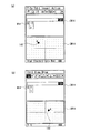
また、図22(a)に示す幾何ウィンドウGW24において関数グラフオブジェクト240の移動操作を入力して表示位置を(b)に示す位置に変更すると、(b)に示すように、計算ウィンドウCW24において、移動操作量に基づいて算出された関数式が表示される(図9ステップA26(YES)→A28→A30(YES)→A32)。さらに、(b)に示す計算ウィンドウCW24関数式を変更すると、(c)に示すように、変更後の関数式に基づいて、幾何ウィンドウGW24に表示される関数グラフオブジェクト240の表示が更新される(図9ステップA34(YES)→A36→A38(YES)→A40)。
【0139】
以上説明したように、第1の実施の形態によれば、互いに表示形態が異なる幾何ウィンドウと計算ウィンドウの内、何れか一方の画面の表示内容が選択されてコピー操作がなされ、他方の画面が指定されてペースト操作がなされた際に、当該選択された一方の画面の表示内容を、他方の画面の表示形態に応じて表示させるとともに、当該コピー元の幾何図形オブジェクト又は計算データと、コピー先の計算データ又は幾何図形オブジェクトの間に、双方を関連付けるリンクを形成させることができる。
【0140】
即ち、例えば、幾何ウィンドウに表示された幾何図形オブジェクトを選択し、ドラッグアンドドロップ操作により計算ウィンドウ上に移動させることにより、幾何ウィンドウ上で選択した幾何図形オブジェクトに対応する計算データ(数式)を計算ウィンドウのカーソル位置に表示させるとともに、当該幾何図形オブジェクトと計算データとを相互に関連付けたリンクを形成させることができる。これによれば、例えば、幾何ウィンドウに表示される幾何図形オブジェクトを選択し、当該幾何図形オブジェクトの変形操作を入力して表示位置を変更すると、当該変形操作に応じて、幾何図形オブジェクトを変形させることができる。
【0141】
また、計算ウィンドウに表示された計算データ(数式)を選択し、ドラッグアンドドロップ操作により幾何ウィンドウ上に移動させることにより、計算ウィンドウ上で選択した計算データ(数式)に基づく幾何図形オブジェクトを幾何ウィンドウに表示させるとともに、当該計算データと幾何図形オブジェクトとを相互に関連付けたにリンクを形成させることができる。これによれば、例えば、計算ウィンドウで計算データの変更操作を入力すると、当該変更操作に応じて、幾何図形オブジェクトを変形させることができる。
【0142】
従って、リンク形成機能を、幾何図形オブジェクトの変形操作後の計算データ(数式、座標等)の変化や、当該計算データの変更操作後の幾何図形オブジェクトの変化の学習に役立てることができる。
【0143】
尚、上記した第1の実施の形態においては、コピーバッファ85に格納するコピーデータを、テキストデータとした場合について説明したが、幾何図形オブジェクトのデータ形式でコピーバッファ85に格納することとしても構わない。
【0144】
また、幾何アプリケーションに表示される幾何図形オブジェクトの幾何種別は、上記したものに限らず、例えば、陰関数形式やパラメータ形式の曲線、立体図形等であってもよい。
【0145】
〔第2の実施の形態〕
次に、本発明を適用した第2の実施の形態について説明する。図23は、第3の実施の形態における関数電卓200の概念図を示している。同図に示すように、関数電卓200は、CPUにより実行されるプログラム群として、基底クラス210と、幾何アプリケーション220と、計算アプリケーション230と、幾何/計算リンク形成モジュール240と、計算/幾何リンク形成モジュール250とがあり、CPUはこれらのプログラムの実行に際に、RAMの一部であるコピーバッファ260を用いて処理を行う。以下、簡便のため、これらのプログラムを主体として説明するが、実際には、CPUによって実行・実現されるものである。
【0146】
基底クラス210は、関数電卓200の備える各種アプリケーションや各種モジュールを統括的に管理し、関数電卓200の動作を制御するためのプログラムである。特に、基底クラス210は、表示画面上に表示された幾何ウィンドウと計算ウィンドウ間でのドラッグアンドドロップ操作等によるコピーアンドペースト指示を監視し、幾何ウィンドウから計算ウィンドウへのコピーアンドペースト操作を検知した場合に、幾何/計算リンク形成モジュール240を起動し、計算ウィンドウから幾何ウィンドウへのコピーアンドペースト操作を検知した場合に、計算/幾何リンク形成モジュール250を起動する。
【0147】
幾何アプリケーション220は、各種幾何図形描画機能を有するアプリケーションプログラムであり、当該幾何アプリケーション220で利用可能なデータ形式で記述された幾何モデルを扱う。
【0148】
計算アプリケーション230は、各種計算機能を有するアプリケーションプログラムであり、当該計算アプリケーション230で利用可能なデータ形式で記述された数式モデルを扱う。
【0149】
幾何/計算リンク形成モジュール240は、幾何アプリケーション220で作成された幾何モデルの計算アプリケーション230へのコピーアンドペースト指示に応じて、コピーバッファ260に格納された幾何モデルを数式モデルに変換し、当該幾何モデルと数式モデルとを関連付けるリンクを形成する。
【0150】
計算/幾何リンク形成モジュール250は、幾何アプリケーション220で作成された幾何モデルの計算アプリケーション230へのコピーアンドペースト指示に応じて、コピーバッファ260に格納された幾何モデルを数式モデルに変換し、当該幾何モデルと数式モデルとを関連付けるリンクを形成する。
【0151】
コピーバッファ260は、幾何アプリケーション220でコピーされた幾何モデルや、計算アプリケーション230でコピーされた数式モデルを一時的に保持するための記憶領域であり、幾何/計算リンク形成モジュール240が幾何モデルを数式モデルに変換してリンクを形成する際、又は計算/幾何リンク形成モジュール350が数式モデルを幾何モデルに変換してリンクを形成する際の作業領域として使用される。
【0152】
図24は、幾何/計算リンク形成モジュール250による幾何モデルと数式モデル間のリンク形成に係る関数電卓200の動作を示すフローチャートである。基底クラス210が、幾何ウィンドウ上の幾何モデルのコピー操作を検知すると、図24に示すように、先ず、幾何アプリケーション220が、当該選択された幾何モデルをコピーし、基底クラス210を介してコピーバッファ260に格納する(ステップE10)。次いで、幾何/数式変換モジュール240が、コピーバッファ260に格納された幾何モデルを数式モデルに変換して、コピーバッファ260を更新するとともに、当該幾何モデルと数式モデルとの間に、双方を関連付けるリンクを形成する(ステップE12)。次いで、計算アプリケーション230が、コピーバッファ260の数式モデルを読み出して計算ウィンドウのカーソル位置にペーストし、当該数式モデルを計算ウィンドウ上に表示させる(ステップE14)。
【0153】
図25は、計算/幾何リンク形成モジュール250による幾何モデルと数式モデル間のリンク形成に係る関数電卓200の動作を示すフローチャートである。基底クラス210が、計算ウィンドウ上の数式モデルのコピー操作を検知すると、図25に示すように、先ず、計算アプリケーション230が、当該選択された数式モデルをコピーし、基底クラス210を介してコピーバッファ260に格納する(ステップF10)。次いで、計算/幾何変換モジュール250が、コピーバッファ260に格納された幾何モデルを数式モデルに変換して、コピーバッファ260を更新するとともに、当該幾何モデルと数式モデルとの間に、双方を関連付けるリンクを形成する(ステップF12)。次いで、幾何アプリケーション220が、コピーバッファ260の数式モデルを読み出して計算ウィンドウのカーソル位置にペーストし、当該数式モデルを計算ウィンドウ上に表示させる(ステップF14)。
【0154】
以上説明したように、第2の実施の形態によれば、コピー元のアプリケーションのデータの表示形態を、コピー先のアプリケーションのデータの表示形態に変換し、コピー元のデータとコピー先のデータとを関連付けるリンクを形成する処理を記述した変換モジュールをそれぞれ備えることにより、表示形態の異なるアプリケーション間でのリンク形成機能を実現している。
【0155】
尚、上記した第2の実施の形態では、幾何アプリケーションと計算アプリケーション間でのリンク形成機能について説明したが、コピー元のアプリケーションの表示形態をコピー先のアプリケーションの表示形態に変換し、コピー元のデータとコピー先のデータとを関連付ける処理を記述した変換モジュールを追加することにより、例えば、ワープロソフト、表計算ソフト、ペイントソフト、統計ソフト等、表示形態の異なる何れのアプリケーション間におけるコピーデータ間のリンク形成機能を実現することが可能である。
【0156】
例えば、関数電卓300に、幾何モデルをビットマップイメージに変換して、当該幾何モデルとビットマップイメージとを関連付けてリンクを形成する変換モジュール及びビットマップイメージを幾何モデルに変換して、当該ビットマップイメージと幾何モデルとを関連付けてリンクを形成する変換モジュールを追加すれば、幾何アプリケーションと、ペイントソフト等のビットマップイメージを扱う描画アプリケーションとの間のコピーアンドペースト機能を実現することができる。
【0157】
尚、上記した第1〜第2の実施の形態例においては、幾何アプリケーションと計算アプリケーションの2つのアプリケーションを起動して、表示画面上に幾何ウィンドウと計算ウィンドウの2つの画面を表示させた場合について説明したが、3つ以上のアプリケーションを起動し、コピー元の画面とコピー先の画面を適宜選択することとしても勿論構わない。
【0158】
以上、2つの実施の形態について、本発明を関数電卓に適用した場合を例にとって説明したが、本発明である図形表示制御装置を汎用コンピュータやパーソナルコンピュータ等によって実現することも勿論可能である。具体的には、上述した各プログラムをオペレーティングシステム(OS)下で稼動するソフトウェアとして構成させ、ハードディスク、磁気ディスク、光ディスク等の各種記憶媒体に格納する。この場合には、例えば、マウス等のポインティングデバイスを用いたドラッグアンドドロップ操作により、コピーアンドペースト指示を入力する。
【0159】
【発明の効果】
請求項1に記載の発明によれば、数式画面に表示された関数式を指定した後に、関数式の貼り付け先を図形画面に指定すると、指定された関数式に対応するグラフ図形が図形画面に描画されるとともに、このグラフ図形に対応付けて、前記指定された関数式が記憶され、図形変更操作手段により図形画面に表示されたグラフ図形に対して変更操作を行うと、変更されたグラフ図形に対応付けて記憶されている関数式の表示が、前記変更操作されたグラフ図形に応じて変更されるようにしたので、きわめて簡単な操作で数式画面に表示された関数式に対応するグラフ図形が図形画面に表示されるとともに対応付けされ、グラフ図形を変更操作するだけで対応する関数式がグラフ図形に応じて変更される。従って、きわめて簡単な操作によりグラフ図形とそれに対応する数式の関係を学ぶことができる。
【0160】
請求項2に記載の発明によれば、数式変更操作手段により数式画面に表示された関数式の変更操作を行うと、この変更された関数式に対応付けて記憶されているグラフ図形の表示が、変更操作された関数式に応じて変更して描画されるので、例えば関数式のパラメータ等を任意に変更操作して、対応するグラフ図形の変化を視覚的に確認でき、きわめて簡単な操作により数式等とそれに対応するグラフ図形の関係を学ぶことができる。
【0161】
請求項3に記載の発明によれば、対応付関数式記憶手段には、各グラフ図形に対応付けてそれぞれ関数式が記憶されており、前記数式画面に表示された複数の関数式のうち、ユーザにより変更されたグラフ図形に対応付けられて前記対応付関数式記憶手段に記憶された関数式が変更されるので、例えば複数組の関数式とグラフ式が、それぞれ数式画面と図形画面に表示されていても、ユーザが変更したグラフ図形に対応する関数式が適切に変更されて表示される。例えば比較の為に、関数式やグラフ図形を複数組表示させて、所望のグラフ図形を変更すれば、対応する関数式のみ適切に変更され、比較しながら、グラフ図形と関数式の関係を学ぶことができる。
【0162】
請求項4に記載の発明によれば、対応付けて記憶されているグラフ図形又は関数式が識別表示により確認できるので、表示されたグラフ図形や関数式が対応付けされているかどうかを、表示上で直ちに確認できる。
【図面の簡単な説明】
【図1】本発明を適用した関数電卓の概観図の一例を示す図である。
【図2】関数電卓の表示画面の画面遷移例を示す図である。
【図3】第1の実施の形態における関数電卓の構成を示す図である。
【図4】幾何ウィンドウデータの一例を示す図である。
【図5】関数式テーブルの一例を示す図である。
【図6】計算ウィンドウデータの一例を示す図である。
【図7】リンクテーブルの一例を示す図である。
【図8】コピーバッファの一例を示す図である。
【図9】メイン処理の実行に係る関数電卓の動作フローを示す図である。
【図10】データ入力処理の実行に係る関数電卓の動作フローを示す図である。
【図11】コピー/ドラッグ処理の実行に係る関数電卓の動作フローを示す図である。
【図12】変換処理の実行に係る関数電卓の動作フローを示す図である。
【図13】ペースト/ドロップ処理の実行に係る関数電卓の動作フローを示す図である。
【図14】図形表示処理の実行に係る関数電卓の動作フローを示す図である。
【図15】リンク形成機能について説明するための図である。
【図16】リンク形成時の画面遷移例を示す図である。
【図17】リンク形成時の画面遷移例を示す図である。
【図18】リンク形成時の画面遷移例を示す図である。例を示す図である。
【図19】リンク形成時の画面遷移例を示す図である。
【図20】リンク形成時の画面遷移例を示す図である。
【図21】リンク形成時の画面遷移例を示す図である。
【図22】リンク形成時の画面遷移例を示す図である。
【図23】第2の実施の形態における関数電卓の概念図を示す図である。
【図24】幾何/計算リンク形成モジュールによる幾何モデルと数式モデル間のリンク形成に係る関数電卓の動作を示すフローチャートである。
【図25】計算/幾何リンク形成モジュールによる幾何モデルと数式モデル間のリンク形成に係る関数電卓の動作を示すフローチャートである。
【符号の説明】
1 関数電卓
10 CPU
20 入力部
30 タブレット
40 位置検出回路
50 表示部
60 通信部
70 ROM
72 メイン処理プログラム
72a データ入力処理プログラム
72b コピー/ドラッグ処理プログラム
72c ペースト/ドロップ処理プログラム
80 RAM
81 幾何ウィンドウデータ
82 計算ウィンドウデータ
83 関数式テーブル
84 リンクテーブル
85 コピーバッファ
90 サーバ
N1 ネットワーク[0001]
BACKGROUND OF THE INVENTION
The present invention relates to a graphic display control device andGraphic display controlRegarding the program.
[0002]
[Prior art]
2. Description of the Related Art Conventionally, an apparatus having a drawing function for drawing a geometric figure is known. For example, in a scientific calculator with abundant functions such as equation calculation, matrix calculation, complex number calculation, financial calculation function, statistical function, etc., a scientific calculator with the above-mentioned drawing function (hereinafter referred to as “functional calculator”) Is known). For example, the scientific calculator can display calculation results of various technical calculations using a calculation function in a graph or display a graphic expression by inputting a graphic expression. Therefore, it is widely used for studying the relationship between character data such as mathematical formulas and graphs and figures in educational settings.
[0003]
Further, in the scientific calculator as described above, the outline of the graph to be displayed is input by handwriting with an input pen or the like, and by inputting the coordinates on the graph, the graph expression is specified, and based on the graph expression One having a function of displaying an accurate graph is known (for example, see Patent Document 1).
[0004]
[Patent Document 1]
JP-A-9-282476
[0005]
[Problems to be solved by the invention]
However, with a conventional scientific calculator, in order to display a graph expression or figure from a graph display by inputting a function expression or figure expression, a different series of operations is required depending on the purpose. . Therefore, in order to learn and analyze the relationship between character data such as mathematical formulas and graphs and figures using a conventional scientific calculator, it is necessary to perform each series of operations, and the operation of the scientific calculator is well understood. There was a need.
[0006]
The present invention has been made in view of the above-described conventional circumstances, and realizes a graphic display control device capable of understanding the relationship between character data such as mathematical formulas and the corresponding graphs and graphics by a very simple operation. The purpose is to do.
[0007]
[Means for Solving the Problems]
In order to solve the above problems, the graphic display control device according to the first aspect of the present invention provides:Graphic screen for displaying graph shapes ( GW1 in FIG. ) And formula screen to display function formula ( CW1 in FIG. ) Display part consisting of ( 50 in FIG. ) In the figure display control apparatus, the function formula designating means (
[0009]
According to the invention described in
[0010]
The invention according to claim 22. The graphic display control apparatus according to
[0011]
According to the invention described in
[0012]
A graphic display control device according to a third aspect is the first aspect.Or 2In the graphic display control device described inThe associated function expression storage means stores a function expression in association with each graph figure (FIGS. 5, 6, and 7), and the change display control means includes a plurality of functions displayed on the equation screen. Of the formulas, control is performed so as to change the function formula stored in the associated function formula storage means in association with the changed graph figure (A30 to A32 in FIG. 9).It is characterized by that.
[0013]
According to the invention described in
[0014]
The invention according to
[0015]
According to the invention of
[0018]
DETAILED DESCRIPTION OF THE INVENTION
Hereinafter, with reference to FIG. 1 to FIG. 25, an embodiment when the graphic display control device according to the present invention is applied to a scientific calculator will be described in detail.
[0019]
FIG. 1 shows an example of an overview diagram of a
[0020]
[First Embodiment]
First, a first embodiment of a scientific calculator to which the present invention is applied will be described. In the following description, the present invention is applied to a geometric application program for realizing a geometric drawing function (hereinafter referred to as “geometric application” as appropriate) and a calculation application program for realizing a calculation function (hereinafter referred to as “calculation as appropriate”). A case where it is applied to a scientific calculator equipped with “application”) will be described as an example.
[0021]
In the first embodiment, one geometric figure displayed on a geometric application screen (hereinafter referred to as “geometric window”) and a calculation application screen (hereinafter referred to as “calculation window”) are displayed. When a link for associating both is formed with one calculation data, the other is automatically changed in accordance with one of the change operations, and the display is updated.
[0022]
In the first embodiment, the
[0023]
FIG. 2 shows a screen transition example of the display screen of the
[0024]
The geometric figure object displayed in the geometric window GW1 can be selected with an input pen or the like, and the geometric figure object can be rotated or translated.
[0025]
Furthermore, by setting a link mode, a link that associates both is formed between an arbitrary geometric object displayed on the geometric window GW1 and arbitrary calculation data displayed on the calculation window CW1. Can do.
[0026]
Here, a geometric figure is a thing that can be represented as a diagram such as a point, a line (including a line segment and a straight line), a vector, a circle (including an arc), a polygon, and a function graph. An object is a unit of a geometric figure drawn (displayed). For example, when a geometric figure of a circle is drawn, the drawn diagram (circle) is called a circle object. When a circle and a straight line are drawn, the portion of the diagram related to the circle is called a circle object, and the portion of the diagram related to the straight line is called a straight line object.
[0027]
In the
[0028]
Here, for example, when a
[0029]
Here, the copy-and-paste operation refers to designating desired data (graphics, images, character strings, etc.) on the screen with a pointing device (pen, mouse, etc.), and further replacing the data or an alternative to the data. This is an operation for designating the position to be pasted with a pointing device (such as a pen or a mouse). This operation is performed, for example, by executing a copy command after specifying desired data on the screen with a pen, and further specifying a paste destination position with a pen and executing the copy command.
[0030]
In addition, for example, by touching and specifying desired data on the screen with a pen, an operation of moving while maintaining the touch (hereinafter referred to as a drag operation), and a state in which the touch of the desired data is maintained following the drag operation Therefore, it can be realized by an operation of raising the pen at the position of the pasting destination (this operation is hereinafter referred to as a drop operation).
[0031]
An input pen (for example, the
[0032]
When a copy and paste operation is input, a link for associating both is automatically formed between the corresponding geometric figure object and the calculation data. As shown in FIG. 2A, a link mark M1 is displayed in the vicinity of the calculation data associated with the geometric figure object in the calculation window CW1.
[0033]
In the geometric window GW1 shown in (a), when the
[0034]
FIG. 3 is a diagram illustrating a functional configuration example of the
[0035]
The
[0036]
The
[0037]
The
[0038]
In particular, data specified on one of the geometric window and the calculation window can be copied to the other screen by a drag-and-drop operation using the
[0039]
The
[0040]
Specifically, for example, the program stored in the
[0041]
The
[0042]
The
[0043]
Further, the
[0044]
The
[0045]
The
[0046]
FIG. 4 shows an example of the
[0047]
That is, in the
[0048]
For example, when the geometric type is “straight line”, the coordinates of the designated two points are held as the first specific point coordinates and the second specific point coordinates in the
[0049]
In addition, when the geometric type of the geometric figure instructed to be drawn in the geometric window is a function graph, the
[0050]
FIG. 5 shows an example of the function formula table 83. As shown in the figure, the function formula table 83 is a data table in which a geometric figure ID and a function formula are associated with each other. When the function graph object is drawn in the geometric window, the
[0051]
FIG. 6 shows an example of the
[0052]
Further, the
[0053]
FIG. 7 is a diagram illustrating an example of the link table 84. As shown in the figure, the link table 84 is a data table in which a geometric figure ID and a mathematical expression ID are associated with each other. When copying and pasting from a geometric figure object to calculation data by copying and pasting, or when copying and pasting from calculation data to a geometric figure object, the
[0054]
More specifically, when the
[0055]
FIG. 8 shows an example of the
[0056]
The
[0057]
Then, for example, when copying the geometric figure object selected in the geometric window to the calculation window, the
[0058]
Next, the operation of the
[0059]
FIG. 9 is a flowchart showing the operation of the
[0060]
Moreover, CPU10 sets link mode, when link mode setting operation by a user is detected (step A14: YES) (step A16).
[0061]
If the
[0062]
Further, when the
[0063]
Further, when the
[0064]
Then, the
[0065]
Further, when the
[0066]
Then, the
[0067]
And CPU10 complete | finishes this process, when the completion | finish operation by a user is detected (step A42: YES). Hereinafter, each of the data input process in step A12, the copy / drag process in step A20, and the paste / drop process in step A24 will be described with reference to FIGS.
[0068]
First, the data input process will be described. FIG. 10 is a flowchart showing the operation of the
[0069]
When the text input at the cursor position is impossible, the
[0070]
When command data is input (step B16: YES), the
[0071]
If the input command data is a function graph drawing / setting command (step B20: YES), the
[0072]
Further, when an instruction to open / close the window is input (step B26: YES), the
[0073]
Next, the copy / drag process will be described. FIG. 11 is a flowchart showing the operation of the
[0074]
When the type of the copy / drag source window is a text window (for example, a calculation window) (step C12: YES), the
[0075]
When the detected copy / drag source window type is a geometric window (for example, geometric window) (step C22: YES), the
[0076]
Subsequently, the
[0077]
FIG. 12 is a flowchart showing the operation of the
[0078]
When the
[0079]
On the other hand, when the
[0080]
On the other hand, when the
[0081]
On the other hand, when the
[0082]
On the other hand, when the
[0083]
When the link mode is set after execution of any one of steps C286, C292, C298, C304, and C310 (step C312: YES), the
[0084]
Next, the
[0085]
On the other hand, when the value of the variable i and the figure block count k are the same (step C316: YES), the
[0086]
Next, the paste / drop process will be described. FIG. 13 is a flowchart showing the operation of the
[0087]
Further, when there is valid data in the
[0088]
When the geometric link flag associated with the character string is set to “ON” in the copy buffer 85 (step D18: YES), the
[0089]
If the detected paste / drop destination window type is a geometric window (for example, a geometric window) (step D22: YES), the
[0090]
FIG. 14 is a flowchart showing the operation of the
[0091]
Then, when the read data in the
[0092]
If the read data in the
[0093]
If the read data in the
[0094]
If the read data in the
[0095]
Next, the
[0096]
Then, when the read data in the
[0097]
Further, after executing any one of steps D262, D266, D270, D274, D278, and D286, the
[0098]
Then, when there is next data in the copy buffer 85 (step D292), the
[0099]
Next, a function of forming a link between the geometric figure object in the geometric window and the calculation data in the calculation window will be described.
[0100]
FIG. 15 is a diagram for explaining the link forming function in the first embodiment. For example, in the geometric window GW10, first, a straight line drawing command is designated using the
[0101]
Next, when the
[0102]
Then, if the
[0103]
Then, for example, when the
[0104]
Further, in the calculation window CW10 shown in FIG. 15B, when the calculation data “y = x + 2” is changed to “y = −x”, the geometric window GW10 is based on the changed calculation data “y = −x”. The display of the
[0105]
FIG. 16 is a diagram illustrating an example of screen transition during link formation. The calculation window CW12 shown in FIG.2+ Y2−16 = 0 ”,“ −2x-6 ”,“ x2”Is displayed, and the calculation data“ x2+ Y2The link mark M12 is displayed in “−16 = 0”, and the link mark M13 is displayed in the calculation data “−2x-6”. Also, in the calculation window CW12, a
[0106]
More specifically, for example, in the geometric window GW12 shown in FIG. 16 (a), for example, first, using the input pen or the like, the circle equation “x”2+ Y2−16 = 0 ”(FIG. 9, step A10 (YES) → A12 → FIG. 10 step B10 (YES) → B12 (YES) → B14). In addition, the link mode can be changed by operating a button using an input pen or the like. When a setting operation is input (step A14 in FIG. 9), the link mode is set (step A16 in FIG. 9).
[0107]
Then, the function expression is highlighted and designated as a copy target by a range designation operation using an input pen or the like, and when a drag operation is started, copy / drag processing is performed, and the specified circle equation is stored in the
[0108]
When the character string area where the drag operation is started is dropped on the geometric window GW12 (FIG. 9, step A22 (YES) → A24 → FIG. 13 step D10 → D12 (YES) → D14 (NO) → D22 (YES)) → D24. → D26 → FIG. 14 Step D272 (YES)), the
[0109]
Further, for example, in the geometric window GW12, first, a line drawing command is designated using an input pen or the like, and a desired position is touched to draw the line object 122 (FIG. 9, step A10 (YES) → A12 → FIG. 10 steps B16 (YES) → B18 → B20 (NO)). When a link mode setting operation is input by a button operation using an input pen or the like (step A14 in FIG. 9), the link mode is set (step A16 in FIG. 9).
[0110]
Next, when the
[0111]
Then, when the
[0112]
When the calculation data “−2x−6” is changed to “x−2” in the calculation window CW12 shown in FIG. 16A, as shown in FIG. 16B, the calculation data “x-2” after the change is changed. Thus, the display of the
[0113]
Then, when a movement operation of the
[0114]
Hereinafter, a link forming function between a geometric window displaying geometric objects of different geometric types and a calculation window will be described with reference to screen transition examples shown in FIGS.
[0115]
For example, in the geometric window GW14 shown in FIG. 17A, first, a point drawing command is designated using an input pen or the like, and a
[0116]
Next, when the
[0117]
Then, when the
[0118]
In addition, when a movement operation of the
[0119]
Further, in the calculation window CW16 shown in FIG. 18A, first, a vector drawing command is designated using an input pen or the like, and a
[0120]
Next, when the
[0121]
Then, when the
[0122]
For example, in the calculation window GW16 shown in FIG. 18A, when the 1 × 2 matrix representing the vector coordinates is edited, as shown in FIG. 18B, it is displayed in the geometric window GW16 based on the changed vector coordinates. The display of the
[0123]
Further, in the geometric window GW18 shown in FIG. 19A, first, a line segment drawing command is designated using an input pen or the like, and a
[0124]
Next, when the
[0125]
Then, when the
[0126]
Further, when a rotation operation is input to the
[0127]
Further, in the geometric window GW20 shown in FIG. 20A, first, an arc drawing command is designated using an input pen or the like, and a desired position is touched to draw the arc object 200 (step A10 (YES in FIG. 9). ) → A12 → FIG. 10 Step B16 (YES) → B18 → B20 (NO)). When a link mode setting operation is input by a button operation using an input pen or the like (step A14 in FIG. 9), the link mode is set (step A16 in FIG. 9).
[0128]
Next, when the
[0129]
Then, when the
[0130]
Also, when a rotation / movement operation for the
[0131]
Further, in the calculation window CW22 shown in FIG. 21A, for example, first, an elliptic equation is input using an input pen or the like (step A10 (YES) → A12 → FIG. 10 step B10 (YES) → B12 in FIG. 9). (YES) → B14). When a link mode setting operation is input by a button operation using an input pen or the like (step A14 in FIG. 9), the link mode is set (step A16 in FIG. 9).
[0132]
Then, the circle equation is highlighted and designated as a copy target by a range designation operation using an input pen or the like, and when a drag operation is started, copy / drag processing is performed, and the designated elliptic equation is copied to the
[0133]
When the character string area where the drag operation is started is dropped on the geometric window GW22 (FIG. 9, step A22 (YES) → A24 → FIG. 13 step D10 → D12 (YES) → D14 (NO) → D22 (YES)) → D24. → D26 → FIG. 14 Step D272 (YES)), the
[0134]
When the elliptic equation is changed in the calculation window CW22 shown in FIG. 21A, the
[0135]
Further, in the geometric window GW24 shown in FIG. 22A, for example, first, a function formula is input using an input pen or the like (step A10 (YES) in FIG. 9 → A12 → step B10 (YES) in FIG. 10 → B12 ( YES) → B14). When a link mode setting operation is input by a button operation using an input pen or the like (step A14 in FIG. 9), the link mode is set (step A16 in FIG. 9).
[0136]
When the function expression is highlighted and designated as a copy target by a range designation operation using an input pen or the like and a drag operation is started, copy / drag processing is performed, and the designated function expression is stored in the
[0137]
When the character string area where the drag operation is started is dropped on the geometric window GW24 (FIG. 9, step A22 (YES) → A24 → FIG. 13 step D10 → D12 (YES) → D14 (NO) → D22 (YES)) → D24. → D26 → FIG. 14 Step D276 (YES)), the
[0138]
Further, when a movement operation of the
[0139]
As described above, according to the first embodiment, the display content of either one of the geometric window and the calculation window having different display forms is selected and the copy operation is performed, and the other screen is displayed. When the specified paste operation is performed, the display content of the selected one screen is displayed according to the display form of the other screen, and the geometric object or calculation data of the copy source and the copy destination A link for associating both of the calculated data and the geometric object can be formed.
[0140]
That is, for example, by selecting a geometric figure object displayed in the geometric window and moving it onto the calculation window by drag and drop operation, calculation data (formula) corresponding to the geometric figure object selected on the geometric window is calculated. In addition to being displayed at the cursor position in the window, it is possible to form a link that correlates the geometric figure object with the calculation data. According to this, for example, when a geometric figure object displayed in the geometric window is selected and a deformation operation of the geometric figure object is input to change the display position, the geometric figure object is deformed according to the deformation operation. be able to.
[0141]
In addition, by selecting calculation data (formula) displayed in the calculation window and moving it onto the geometric window by drag and drop operation, a geometric figure object based on the calculation data (formula) selected on the calculation window is displayed in the geometric window. And a link can be formed by associating the calculated data with the geometric figure object. According to this, for example, when a calculation data change operation is input in the calculation window, the geometric figure object can be deformed in accordance with the change operation.
[0142]
Therefore, the link formation function can be used for learning of changes in calculation data (formulas, coordinates, etc.) after a deformation operation of the geometric figure object and changes in the geometric figure object after a change operation of the calculation data.
[0143]
In the first embodiment described above, the case where the copy data stored in the
[0144]
Further, the geometric type of the geometric figure object displayed in the geometric application is not limited to the above, but may be, for example, an implicit function form, a parameter form curve, a solid figure, or the like.
[0145]
[Second Embodiment]
Next, a second embodiment to which the present invention is applied will be described. FIG. 23 shows a conceptual diagram of a
[0146]
The
[0147]
The
[0148]
The
[0149]
The geometric / computation
[0150]
The calculation / geometric
[0151]
The
[0152]
FIG. 24 is a flowchart showing the operation of the
[0153]
FIG. 25 is a flowchart showing the operation of the
[0154]
As described above, according to the second embodiment, the display form of the copy source application data is converted into the copy destination application data display form, and the copy source data and the copy destination data By providing conversion modules each describing a process for forming a link for associating links, a link forming function between applications having different display forms is realized.
[0155]
In the above-described second embodiment, the link forming function between the geometric application and the calculation application has been described. However, the display form of the copy source application is converted into the display form of the copy destination application, and the copy source By adding a conversion module that describes the process of associating data with the data at the copy destination, for example, between copy data between applications with different display formats, such as word processing software, spreadsheet software, paint software, statistical software, etc. It is possible to realize a link forming function.
[0156]
For example, the scientific calculator 300 converts a geometric model into a bitmap image, associates the geometric model with the bitmap image and forms a link, and converts the bitmap image into a geometric model to convert the bitmap into the bitmap. If a conversion module that associates an image with a geometric model to form a link is added, a copy and paste function between the geometric application and a drawing application that handles bitmap images, such as paint software, can be realized.
[0157]
In the first to second embodiments described above, when two applications, a geometric application and a calculation application, are activated and two screens, a geometric window and a calculation window, are displayed on the display screen. As described above, it is of course possible to start three or more applications and appropriately select a copy source screen and a copy destination screen.
[0158]
As described above, the two embodiments have been described by taking the case where the present invention is applied to a scientific calculator as an example. However, the graphic display control apparatus according to the present invention can be realized by a general-purpose computer, a personal computer, or the like. Specifically, each of the above-described programs is configured as software that runs under an operating system (OS), and is stored in various storage media such as a hard disk, a magnetic disk, and an optical disk. In this case, for example, a copy and paste instruction is input by a drag and drop operation using a pointing device such as a mouse.
[0159]
【The invention's effect】
According to the invention of
[0160]
According to invention of
[0161]
According to invention of
[0162]
According to invention of
[Brief description of the drawings]
FIG. 1 is a diagram showing an example of an overview diagram of a scientific calculator to which the present invention is applied.
FIG. 2 is a diagram illustrating a screen transition example of a display screen of a scientific calculator.
FIG. 3 is a diagram illustrating a configuration of a scientific calculator according to the first embodiment.
FIG. 4 is a diagram illustrating an example of geometric window data.
FIG. 5 is a diagram illustrating an example of a function expression table.
FIG. 6 is a diagram illustrating an example of calculation window data.
FIG. 7 is a diagram illustrating an example of a link table.
FIG. 8 is a diagram illustrating an example of a copy buffer.
FIG. 9 is a diagram illustrating an operation flow of a scientific calculator related to execution of main processing.
FIG. 10 is a diagram showing an operation flow of a scientific calculator related to execution of data input processing.
FIG. 11 is a diagram showing an operation flow of a scientific calculator related to execution of copy / drag processing;
FIG. 12 is a diagram illustrating an operation flow of a scientific calculator related to execution of conversion processing;
FIG. 13 is a diagram illustrating an operation flow of a scientific calculator related to execution of paste / drop processing.
FIG. 14 is a diagram showing an operation flow of a scientific calculator related to execution of graphic display processing.
FIG. 15 is a diagram for explaining a link forming function;
FIG. 16 is a diagram showing an example of screen transition when a link is formed.
FIG. 17 is a diagram illustrating an example of screen transition when a link is formed.
FIG. 18 is a diagram illustrating an example of screen transition when a link is formed. It is a figure which shows an example.
FIG. 19 is a diagram showing an example of screen transition when a link is formed.
FIG. 20 is a diagram showing an example of screen transition when a link is formed.
FIG. 21 is a diagram illustrating an example of screen transition when a link is formed.
FIG. 22 is a diagram showing an example of screen transition when a link is formed.
FIG. 23 is a diagram illustrating a conceptual diagram of a scientific calculator according to a second embodiment.
FIG. 24 is a flowchart showing an operation of a scientific calculator related to link formation between a geometric model and a mathematical model by a geometric / computation link formation module;
FIG. 25 is a flowchart showing the operation of a scientific calculator related to link formation between a geometric model and a mathematical model by a calculation / geometric link formation module;
[Explanation of symbols]
1 Scientific calculator
10 CPU
20 Input section
30 tablets
40 Position detection circuit
50 display section
60 Communication Department
70 ROM
72 Main processing program
72a Data input processing program
72b Copy / drag processing program
72c Paste / Drop Processing Program
80 RAM
81 Geometric window data
82 Calculation window data
83 Function expression table
84 Link table
85 copy buffer
90 servers
N1 network
Claims (5)
前記数式画面に表示された関数式を指定する関数式指定手段と、
この関数式指定手段により関数式が指定された後に、当該関数式の貼り付け先を指定する貼付先指定手段と、
この貼付先指定手段により前記図形画面が指定された場合に、前記関数式指定手段により指定された関数式に対応するグラフ図形を前記図形画面に描画するグラフ描画手段と、
このグラフ描画手段により描画されたグラフ図形に対応付けて、前記関数式指定手段により指定された関数式を記憶する対応付関数式記憶手段と、
前記図形画面に表示されたグラフ図形に対して変更操作を行う図形変更操作手段と、
この図形変更操作手段により変更されたグラフ図形に対応付けて、前記対応付関数式記憶手段に記憶されている関数式の前記数式画面の表示を、前記変更操作されたグラフ図形に応じて変更するように表示制御する変更表示制御手段と、
を備えることを特徴とする図形表示制御装置。 In a graphic display control device comprising a display unit comprising a graphic screen for displaying a graphic graphic and a mathematical expression screen for displaying a function expression,
A function formula specifying means for specifying the function formula displayed on the formula screen;
After the function expression is specified by the function expression specifying means, the paste destination specifying means for specifying the paste destination of the function expression;
A graph drawing means for drawing a graph figure corresponding to the function expression specified by the function expression specifying means when the figure screen is specified by the paste destination specifying means;
Corresponding function expression storage means for storing the function expression specified by the function expression specifying means in association with the graph figure drawn by the graph drawing means;
Graphic change operation means for performing a change operation on the graph graphic displayed on the graphic screen;
Corresponding to the graph figure changed by the figure changing operation means, the display of the mathematical expression screen of the function expression stored in the associated function expression storage means is changed according to the changed graphic figure. Change display control means for controlling the display,
A graphic display control device comprising:
この数式変更操作手段により変更操作された関数式に対応付けて、前記対応付関数式記憶手段に記憶されているグラフ図形の前記図形画面の表示を、前記変更操作された関数式に応じて変更して描画する変更描画手段と、
を備えることを特徴とする請求項1に記載の図形表示制御装置。 Formula change operation means for performing change input of the function formula displayed on the formula screen;
Corresponding to the function expression changed by the expression changing operation means, the display of the graphic screen of the graph figure stored in the associated function expression storage means is changed according to the function expression changed. Change drawing means for drawing,
Graphic display control device according to claim 1, characterized in Rukoto equipped with.
前記変更表示制御手段は、前記数式画面に表示された複数の関数式のうち、前記変更されたグラフ図形に対応付けて、前記対応付関数式記憶手段に記憶されている関数式を変更するように制御することを特徴とする請求項1又は2に記載の図形表示制御装置。 The associated function expression storage means stores a function expression in association with each graph figure,
The change display control means changes the function expression stored in the associated function expression storage means in association with the changed graph figure among the plurality of function expressions displayed on the equation screen. graphic display control device according to claim 1 or 2, characterized in that controlled.
備えることを特徴とする請求項1〜3の何れか一項に記載の図形表示制御装置。 Correspondence identification display means for performing identification display indicating that the graph graphic or the function expression stored in association with the correspondence function expression storage means is associated.
Graphic display control device according to any one of claims 1-3, characterized in that it comprises.
前記コンピュータを、 The computer,
前記表示部に対して、グラフ図形を表示する図形画面と関数式を表示する数式画面とを設定する手段、 Means for setting a graphic screen for displaying a graph graphic and a mathematical expression screen for displaying a function equation on the display unit;
前記数式画面に表示された関数式を指定する関数式指定手段、 A function formula specifying means for specifying the function formula displayed on the formula screen;
この関数式指定手段により関数式が指定された後に、当該関数式の貼り付け先を指定する貼付先指定手段、 After the function expression is specified by the function expression specifying means, the paste destination specifying means for specifying the paste destination of the function expression,
この貼付先指定手段により前記図形画面が指定された場合に、前記関数式指定手段により指定された関数式に対応するグラフ図形を前記図形画面に描画するグラフ描画手段、 Graph drawing means for drawing a graph figure corresponding to the function expression specified by the function expression specifying means on the figure screen when the figure screen is specified by the paste destination specifying means;
このグラフ描画手段により描画されたグラフ図形に対応付けて、前記関数式指定手段により指定された関数式を前記記憶部に記憶する対応付関数式記憶手段、 Corresponding function expression storage means for storing the function expression specified by the function expression specifying means in the storage unit in association with the graph figure drawn by the graph drawing means;
前記図形画面に表示されたグラフ図形に対して変更操作を行う図形変更操作手段と、 Graphic change operation means for performing a change operation on the graph graphic displayed on the graphic screen;
この図形変更操作手段により変更されたグラフ図形に対応付けて、前記記憶部の前記対応付関数式記憶手段に記憶されている関数式の前記数式画面の表示を、前記変更操作されたグラフ図形に応じて変更するように表示制御する変更表示制御手段、In association with the graph graphic changed by the graphic change operation means, the display of the mathematical expression screen of the functional expression stored in the associated functional expression storage means of the storage unit is changed to the changed graphic graphic. Change display control means for performing display control so as to change according to,
として機能させるための図形表示制御プログラム。 Graphic display control program to function as
Priority Applications (10)
| Application Number | Priority Date | Filing Date | Title |
|---|---|---|---|
| JP2002287301A JP3757925B2 (en) | 2002-09-30 | 2002-09-30 | Graphic display control apparatus and graphic display control program |
| EP03751294.4A EP1556774B1 (en) | 2002-09-30 | 2003-09-30 | Graphic display control apparatus and program |
| EP12152149.6A EP2466482B8 (en) | 2002-09-30 | 2003-09-30 | Graphic display control apparatus and program |
| CNB038019078A CN100338599C (en) | 2002-09-30 | 2003-09-30 | Graphic display control apparatus and program |
| CNB2007101008640A CN100461083C (en) | 2002-09-30 | 2003-09-30 | Graphic display control apparatus and program |
| TW092126933A TWI243316B (en) | 2002-09-30 | 2003-09-30 | Graphic display control apparatus, graphic display control method, mathematic display control apparatus and mathematic display control method |
| EP12152150.4A EP2453345B1 (en) | 2002-09-30 | 2003-09-30 | Graphic display control apparatus and program |
| PCT/JP2003/012517 WO2004029788A2 (en) | 2002-09-30 | 2003-09-30 | Graphic display control apparatus and program |
| US10/869,744 US7289120B2 (en) | 2002-09-30 | 2004-06-15 | Graphic display control apparatus and program |
| US11/734,169 US20070188496A1 (en) | 2002-09-30 | 2007-04-11 | Graphic display control apparatus and program |
Applications Claiming Priority (1)
| Application Number | Priority Date | Filing Date | Title |
|---|---|---|---|
| JP2002287301A JP3757925B2 (en) | 2002-09-30 | 2002-09-30 | Graphic display control apparatus and graphic display control program |
Publications (3)
| Publication Number | Publication Date |
|---|---|
| JP2004126769A JP2004126769A (en) | 2004-04-22 |
| JP2004126769A5 JP2004126769A5 (en) | 2005-10-20 |
| JP3757925B2 true JP3757925B2 (en) | 2006-03-22 |
Family
ID=32280147
Family Applications (1)
| Application Number | Title | Priority Date | Filing Date |
|---|---|---|---|
| JP2002287301A Expired - Fee Related JP3757925B2 (en) | 2002-09-30 | 2002-09-30 | Graphic display control apparatus and graphic display control program |
Country Status (2)
| Country | Link |
|---|---|
| JP (1) | JP3757925B2 (en) |
| CN (2) | CN100461083C (en) |
Families Citing this family (23)
| Publication number | Priority date | Publication date | Assignee | Title |
|---|---|---|---|---|
| JP4888071B2 (en) * | 2006-11-15 | 2012-02-29 | 富士通株式会社 | Program, copy and paste processing method, apparatus and recording medium |
| CN101315633B (en) * | 2008-06-03 | 2012-01-25 | 深圳市蓝韵实业有限公司 | Integrated reduced graph implementing method based on single screen |
| JP2009294926A (en) | 2008-06-05 | 2009-12-17 | Casio Comput Co Ltd | Electronic calculator |
| US8250482B2 (en) * | 2009-06-03 | 2012-08-21 | Smart Technologies Ulc | Linking and managing mathematical objects |
| JP4759081B2 (en) * | 2009-11-11 | 2011-08-31 | 1stホールディングス株式会社 | Chart drawing apparatus and chart drawing method |
| JP4858625B2 (en) * | 2010-03-31 | 2012-01-18 | カシオ計算機株式会社 | Information display device and program |
| JP4853578B2 (en) * | 2010-04-16 | 2012-01-11 | カシオ計算機株式会社 | Graph display device and program |
| JP5716479B2 (en) * | 2011-03-25 | 2015-05-13 | カシオ計算機株式会社 | Electronic device and program |
| EP2538346A3 (en) * | 2011-06-23 | 2013-10-02 | Casio Computer Co., Ltd. | Expression input apparatus, expression display apparatus, expression input method, expression display method, recording medium storing expression input control program, and recording medium storing expression display control program |
| WO2012103839A2 (en) * | 2012-03-29 | 2012-08-09 | 华为技术有限公司 | Data block processing method and system, front end display device, and back end processing device |
| JP5942729B2 (en) * | 2012-09-20 | 2016-06-29 | カシオ計算機株式会社 | Graphic drawing apparatus and program |
| JP6221323B2 (en) * | 2013-04-22 | 2017-11-01 | カシオ計算機株式会社 | Graph display device and control program thereof |
| JP5617961B2 (en) * | 2013-06-04 | 2014-11-05 | カシオ計算機株式会社 | Graphic display device and program |
| JP6331537B2 (en) * | 2014-03-19 | 2018-05-30 | カシオ計算機株式会社 | Variable value display control device, variable value display control method, and program |
| JP6019074B2 (en) * | 2014-09-16 | 2016-11-02 | 京セラドキュメントソリューションズ株式会社 | Electronic device and touch panel operation method |
| CN104462466A (en) * | 2014-12-17 | 2015-03-25 | 北京百度网讯科技有限公司 | Method and device for inquiring mathematic calculation information |
| CN104503957B (en) * | 2015-01-12 | 2018-08-24 | 深圳市心讯网络科技有限公司 | A kind of formula graphic automatic generation method and device |
| CN105893330A (en) * | 2016-03-31 | 2016-08-24 | 珠海格力电器股份有限公司 | Data processing method and device applied to calculator |
| CN114896374A (en) | 2016-04-28 | 2022-08-12 | 荣耀终端有限公司 | Man-machine interaction method and device |
| CN106373169A (en) * | 2016-08-30 | 2017-02-01 | 广东成德电子科技股份有限公司 | Parameter-driven printed circuit board bitmap duplication method and system |
| CN108037877A (en) * | 2017-12-15 | 2018-05-15 | 广州视源电子科技股份有限公司 | Processing method, device, equipment and the storage medium of function curve |
| CN110047117B (en) * | 2019-04-18 | 2023-03-17 | 武汉轻工大学 | Method, device and equipment for drawing curved surface graph and storage medium |
| CN112817505A (en) * | 2021-01-25 | 2021-05-18 | 深圳邦健生物医疗设备股份有限公司 | Software information interface display method and device, storage medium and equipment |
Family Cites Families (6)
| Publication number | Priority date | Publication date | Assignee | Title |
|---|---|---|---|---|
| JPH0792789B2 (en) * | 1985-05-24 | 1995-10-09 | カシオ計算機株式会社 | Graph display device |
| JPS631254U (en) * | 1986-06-19 | 1988-01-07 | ||
| JPH07152917A (en) * | 1993-11-26 | 1995-06-16 | Casio Comput Co Ltd | Graph display device |
| JP3568127B2 (en) * | 1993-11-30 | 2004-09-22 | カシオ計算機株式会社 | Graph display device and graph display method |
| JPH0855123A (en) * | 1994-08-08 | 1996-02-27 | Sharp Corp | Machine translation system with idiom registering function |
| JP3705065B2 (en) * | 1999-02-05 | 2005-10-12 | 日本電気株式会社 | Formula processing system, formula processing method, and recording medium recording formula processing program |
-
2002
- 2002-09-30 JP JP2002287301A patent/JP3757925B2/en not_active Expired - Fee Related
-
2003
- 2003-09-30 CN CNB2007101008640A patent/CN100461083C/en not_active Expired - Fee Related
- 2003-09-30 CN CNB038019078A patent/CN100338599C/en not_active Expired - Fee Related
Also Published As
| Publication number | Publication date |
|---|---|
| CN101030120A (en) | 2007-09-05 |
| JP2004126769A (en) | 2004-04-22 |
| CN1735873A (en) | 2006-02-15 |
| CN100338599C (en) | 2007-09-19 |
| CN100461083C (en) | 2009-02-11 |
Similar Documents
| Publication | Publication Date | Title |
|---|---|---|
| JP3757925B2 (en) | Graphic display control apparatus and graphic display control program | |
| US10649651B2 (en) | Information processing apparatus, program, and operation control method | |
| US7289120B2 (en) | Graphic display control apparatus and program | |
| US7936341B2 (en) | Recognizing selection regions from multiple simultaneous inputs | |
| TW200421257A (en) | Figure display control device and recording medium for executing display of graph and figure | |
| JP5029721B2 (en) | Graph display device and graph display control program | |
| JP2010086230A (en) | Information processing apparatus, information processing method and program | |
| JP3888385B2 (en) | Graphic display control apparatus and graphic display control program | |
| JPH0238978B2 (en) | ||
| US11837206B2 (en) | Multidimensional gestures for music creation applications | |
| JP6330348B2 (en) | Information processing device | |
| JP3785537B2 (en) | Graphic display control apparatus and graphic display control program | |
| JP2004206541A (en) | Graphic display controller and program | |
| JP3988604B2 (en) | Graphic display control apparatus and program | |
| JP2003308147A (en) | Data input device and program | |
| JP2009301523A (en) | Touch-panel type operation electronic apparatus | |
| JP3969306B2 (en) | Graph display control device and program | |
| JP2004094296A (en) | Graphic processor, graphic processing method, and program | |
| JP2004206545A (en) | Electronic instrument and program | |
| JP2004126759A (en) | Figure display control device and program | |
| WO2018132971A1 (en) | Interactive control method and terminal | |
| CN111273802A (en) | Method for moving object on screen and touch display device | |
| JP4670289B2 (en) | Display control device | |
| JPH05135050A (en) | Line segment attribute display method | |
| JPH11161803A (en) | Graph display device, its method and recording medium recording display program |
Legal Events
| Date | Code | Title | Description |
|---|---|---|---|
| A521 | Request for written amendment filed |
Free format text: JAPANESE INTERMEDIATE CODE: A523 Effective date: 20050615 |
|
| A621 | Written request for application examination |
Free format text: JAPANESE INTERMEDIATE CODE: A621 Effective date: 20050615 |
|
| A871 | Explanation of circumstances concerning accelerated examination |
Free format text: JAPANESE INTERMEDIATE CODE: A871 Effective date: 20050701 |
|
| A131 | Notification of reasons for refusal |
Free format text: JAPANESE INTERMEDIATE CODE: A131 Effective date: 20050906 |
|
| A975 | Report on accelerated examination |
Free format text: JAPANESE INTERMEDIATE CODE: A971005 Effective date: 20050722 |
|
| A521 | Request for written amendment filed |
Free format text: JAPANESE INTERMEDIATE CODE: A523 Effective date: 20051104 |
|
| TRDD | Decision of grant or rejection written | ||
| A01 | Written decision to grant a patent or to grant a registration (utility model) |
Free format text: JAPANESE INTERMEDIATE CODE: A01 Effective date: 20051206 |
|
| A61 | First payment of annual fees (during grant procedure) |
Free format text: JAPANESE INTERMEDIATE CODE: A61 Effective date: 20051219 |
|
| R150 | Certificate of patent or registration of utility model |
Free format text: JAPANESE INTERMEDIATE CODE: R150 Ref document number: 3757925 Country of ref document: JP Free format text: JAPANESE INTERMEDIATE CODE: R150 |
|
| FPAY | Renewal fee payment (event date is renewal date of database) |
Free format text: PAYMENT UNTIL: 20090113 Year of fee payment: 3 |
|
| FPAY | Renewal fee payment (event date is renewal date of database) |
Free format text: PAYMENT UNTIL: 20100113 Year of fee payment: 4 |
|
| FPAY | Renewal fee payment (event date is renewal date of database) |
Free format text: PAYMENT UNTIL: 20110113 Year of fee payment: 5 |
|
| FPAY | Renewal fee payment (event date is renewal date of database) |
Free format text: PAYMENT UNTIL: 20110113 Year of fee payment: 5 |
|
| FPAY | Renewal fee payment (event date is renewal date of database) |
Free format text: PAYMENT UNTIL: 20120113 Year of fee payment: 6 |
|
| FPAY | Renewal fee payment (event date is renewal date of database) |
Free format text: PAYMENT UNTIL: 20130113 Year of fee payment: 7 |
|
| FPAY | Renewal fee payment (event date is renewal date of database) |
Free format text: PAYMENT UNTIL: 20130113 Year of fee payment: 7 |
|
| LAPS | Cancellation because of no payment of annual fees |