JP3754286B2 - Data recording method and data recording apparatus - Google Patents
Data recording method and data recording apparatus Download PDFInfo
- Publication number
- JP3754286B2 JP3754286B2 JP2000310111A JP2000310111A JP3754286B2 JP 3754286 B2 JP3754286 B2 JP 3754286B2 JP 2000310111 A JP2000310111 A JP 2000310111A JP 2000310111 A JP2000310111 A JP 2000310111A JP 3754286 B2 JP3754286 B2 JP 3754286B2
- Authority
- JP
- Japan
- Prior art keywords
- data
- midi
- compressed audio
- medium
- audio data
- Prior art date
- Legal status (The legal status is an assumption and is not a legal conclusion. Google has not performed a legal analysis and makes no representation as to the accuracy of the status listed.)
- Expired - Fee Related
Links
Images


Description
【0001】
【発明の属する技術分野】
本発明は、データ記録方法及びデータ記録装置、特に、通信カラオケ(音源を有するカラオケ装置)に使用されているカラオケ情報、即ちMIDI(Musical Instrument Disital Interface)データとMIDIデータによって表示制御されるテキストデータ(歌詞)と画像データ(背景画)とからなるコンテンツのデータ記録に好適であり、これをカラオケ装置や電子楽器に展開するに適したデータ記録方法及びデータ記録装置に関するものである。
【0002】
【従来の技術】
以下、一般的なデータ記録方法及び記録装置並びに記録媒体を用いた従来のカラオケ情報のデータ構造、カラオケ装置及び電子楽器について図面を参照しながら説明する。
【0003】
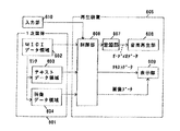
図6は従来のカラオケ装置の概略構成とカラオケ情報のデータ構造を示すブロック図である。図6において、601は1次媒体、602はMIDIデータ領域、603はテキストデータ領域、604は画像データ領域、605は再生装置、606は1次媒体から各種データを受信あるいは読み出し制御を行う制御部、607はMIDIデータに基づき楽音の合成処理を行う音源部、608はアンプやスピーカなどから構成される音楽再生部、609はLCDやCRTなどの表示部、610は入力部である。
【0004】
以上のように構成された従来のカラオケ装置とカラオケ情報のデータ構造の内、まず、カラオケ情報のデータ構造について説明する。図6において、1次媒体601上にあるMIDIデータ(カラオケ楽曲)、テキストデータ(歌詞)、画像データ(背景画)がカラオケ情報の構成要素である。一般的に、MIDIデータはいわゆる演奏データ(音源部607の合成処理のもととなるデータ)と、テキストデータと、画像データを音楽に同期して表示させるための制御データ(イベントデータ)とから構成される。即ち、MIDIデータとテキストデータと画像データは同期して再生、表示されるデータ構造になっている。
【0005】
次に、カラオケ装置について説明する。インターネットなどの回線を通じて送られてきたカラオケコンテンツ、あるいは記録メディアによって供給されるカラオケコンテンツを1次媒体601とする。入力部610が指定したテンポやピッチに従い、制御部606が1次媒体601からMIDIデータ、テキストデータ、画像データを読み込む。MIDIデータは音源部607に転送されオーディオデータに変換され(合成処理がなされ)、音楽再生部608に転送されて音楽が再生される。一方テキストデータや画像データは表示部609に転送され表示される。この時MIDIデータにはテキスト(歌詞)や画像(背景画)を音楽と同期して再生されるような同期情報が含まれている。
【0006】
この構成は電子楽器にもあてはまり、この場合は入力部610が鍵盤や電子楽器パネル上に配設されたスイッチ群に対応し、また、表示部609は電子楽器パネル上に取り付けられたLCDに対応する。電子楽器の場合、通常1次媒体601としてフロッピーディスクなどが多く用いられており、記憶容量の制約上、MIDIデータのみ、あるいはMIDIデータとテキストデータのみを読み込み再生するようになっている。
【0007】
【発明が解決しようとする課題】
しかしながら、このような構成では、必ず音源部を有する装置が必要となり、カラオケボックスに設置しているシンセサイザカラオケ装置やソフトウェア音源などのアプリケーションソフトが組み込まれたパソコン、あるいは電子楽器がなければ再生できないという問題点があった。
【0008】
本発明は、上記従来の問題点を解決するものであり、音源を有していない例えばオーディオ機器を用いてカラオケを楽しむことができる新しいデータ構造に基づくデータ記録方法及びデータ記録装置を提供することを目的とする。
【0009】
【課題を解決するための手段】
本発明のデータ記録方法は、画像データやテキストデータの表示制御情報を有するMIDIデータに基づいて楽音の合成処理を行うことにより音楽再生を行い、再生された音楽に対して音楽圧縮処理を施して得られた圧縮オーディオデータと、前記MIDIデータと、前記画像データと、前記テキストデータを記録媒体に記録する記録方法であって、前記MIDIデータは前記圧縮オーディオデータの再生タイミングを指示する制御情報を含むようにしたものであり、また、本発明のデータ記録装置は、画像データやテキストデータの表示制御情報を有するMIDIデータを入力する1次媒体と、2次媒体と、前記1次媒体からのデータ受信もしくは読み出しを制御する入力制御部と、前記入力制御部が受信もしくは読み出したMIDIデータに基づいて楽音の合成処理を行う音源部と、前記音源部が出力したオーディオデータの圧縮処理を行い圧縮オーディオデータとして出力する圧縮処理部と、前記圧縮オーディオデータと前記入力制御部が受信もしくは読み出したMIDIデータと画像データとテキストデータを前記2次媒体に送信もしくは書き込む出力制御部とを備え、前記2次媒体に送信もしくは書き込まれたMIDIデータは前記圧縮オーディオデータの再生タイミングを指示する制御情報を含むものである。
【0010】
この発明によれば、音源を有していない例えばオーディオ機器を用いて、MIDIデータとMIDIデータによって表示制御されるテキストデータ、画像データに基づくカラオケを楽しむことができる。
【0011】
【発明の実施の形態】
以下、本発明の各実施の形態について図面を参照しながら説明する。なお、前記従来のものと同一の部分及び各実施の形態間で共通の部分については同一符号を用いるものとする。
【0012】
以下、本発明の各実施の形態について図面を参照しながら説明する。
【0013】
(実施の形態1)
図1は本発明のデータ記録方法及び記録装置並びに記録媒体の実施の形態1におけるデータ記録装置の構成を示すブロック図、図2は図1に示す2次媒体とオーディオ機器を用いたカラオケ装置の概略構成とカラオケ情報のデータ構造を示すブロック図、図3は図1に示す装置におけるMIDIデータが圧縮オーディオデータの開始制御を指示する状態の説明図である。
【0014】
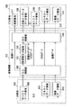
図1において、101は1次媒体601に記録されたコンテンツを変換して2次媒体106に送信あるいは書き込みを行う変換装置、102は1次媒体601から各種データを受信あるいは読み出し制御を行う入力制御部、103はMIDIデータに基づき楽音の合成処理を行う音源部、104は音源部103が生成したオーディオデータの圧縮処理(エンコード)を行い圧縮オーディオデータとして出力する圧縮部、105は圧縮オーディオデータとMIDIデータとテキストデータと画像データと、少なくとも圧縮オーディオデータとMIDIデータとの同期に関係する情報である制御データを2次媒体106に対して送信あるいは書き込みを行う出力制御部、106は2次媒体、107は制御領域、108は圧縮オーディオデータ領域、109はMIDIデータ領域、110はテキストデータ領域、111は画像データ領域である。その他1次媒体601の構成は図6に示したものと同様である。
【0015】
次に、図2において、201はオーディオ機器、202は圧縮オーディオデータ領域108から圧縮オーディオデータを受信もしくは読み出す制御部、203は圧縮オーディオデータの伸張処理(デコード)を行いオーディオデータとして出力する伸張部、204はアンプやスピーカなどから構成される音楽再生部、205はLCDなどの表示部である。なお、MIDIデータが圧縮オーディオデータの開始制御を指示する状態を図3に示してある。
【0016】
以上のように構成されたカラオケ情報のデータ記録装置について、その動作説明をする。まず、1次媒体601からMIDIデータと、テキストデータと、画像データが変換装置101に転送される。なお、1次媒体601は半導体メモリカードやCD(ディスク)などのメモリであってもよいし、また有線や無線伝達経路であっても構わない。またMIDIデータは、従来と同様に、カラオケ楽曲に対応する演奏データと、テキストデータ(歌詞)や画像データ(背景画)の表示制御を行う制御情報を有しているものとする。
【0017】
入力制御部102はMIDIデータを音源部103に転送すると共に、MIDIデータと、テキストデータと、画像データを出力制御部105に転送する。音源部103はMIDIデータに基づいて楽音の合成処理を行うことによってオーディオデータを生成し、圧縮部104はオーディオデータを圧縮(エンコード)し、圧縮オーディオデータとして出力制御部105に転送する。そして出力制御部105は圧縮オーディオデータと、MIDIデータと、テキストデータと、画像データを2次媒体106に転送する。この時、入力制御部102はMIDIデータの先頭(即ち曲の始まり)などの再生タイミングを検出し、再生開始情報として出力制御部105を介して2次媒体106の制御領域に転送し、図3に示すようにMIDIデータの開始に連動してオーディオデータが再生できる仕組みを構築する。なお、2次媒体106上に制御領域を設けずに直接MIDIデータ領域109上のMIDIデータが有する情報として転送するようにしても構わない。なお2次媒体も半導体メモリカードやCD(ディスク)などのメモリであってもよいし、また有線や無線伝達経路であっても構わない。
【0018】
このようにして作成された2次媒体106を用いて、オーディオ機器でカラオケを再生する場合を図2に示す。図2において2次媒体106の各データが制御部202によって読み出される。ここでMIDIデータの再生スピードとオーディオデータの再生スピードが同一になるように読み出し制御されるものとする。圧縮オーディオデータは伸張部203でオーディオデータに伸張され音楽再生部204にてオーディオ信号(カラオケ楽曲)として再生させる。
【0019】
一方、MIDIデータは制御部202において単にテキストデータと画像データの表示タイミングを制御するデータとして作用する。即ち、テキストデータと画像データはMIDIデータのタイミング制御に応じて表示部205で表示される。なお、制御部202にはMIDIデータを解読する機能が含まれていることが条件となるが、通常オーディオ機器が有するマイコンのソフト処理などで対応可能であるので、詳細説明は省略する。ここで制御領域107の再生開始情報によってMIDIデータとオーディオデータの再生開始が一致することになるので、結果的にオーディオ信号(カラオケ楽曲)に同期しながら、テキスト(歌詞)や画像(背景画)が表示されることになる。なお、1次媒体601に基づいて2次媒体106を作成する過程において(図1)、新たにオーディオデータやMIDIデータに対して著作権情報を付加したい場合には、入力制御部102が1次媒体601の各種データを読み込む際に著作権保護情報を生成し、制御領域107に対して、あるいは圧縮オーディオデータ領域108やMIDIデータ領域109上などのデータ本体自体に著作権保護情報を付加するようにすればよい。
【0020】
以上のように、本実施の形態によれば、1次媒体601上のMIDIデータは、既に1次媒体上のテキストデータや画像データの表示タイミングを制御する情報を有しているので、変換装置101がMIDIデータに基づいて生成した圧縮オーディオデータと、入力制御部102が生成したMIDIデータの再生開始と圧縮オーディオデータの再生開始を一致させるための再生開始情報と、1次媒体601上の各種データとを2次媒体106に記憶し、このような2次媒体を用いることにより、音源を有しないオーディオ機器などでもテキスト(歌詞)や画像(背景画)と同期したカラオケを楽しむことが可能となる。
【0021】
(実施の形態2)
図4は本発明のデータ記録方法及び記録装置並びに記録媒体の実施の形態2における電子楽器への展開例を示すブロック図、図5は図4に示す装置におけるRAMのメモリマップである。
【0022】
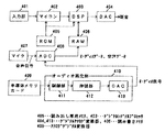
図4において、401は鍵盤などの入力部、402は発音制御を行うマイコン、403は楽音合成処理を行うDSP、404はデジタルアナログ変換器、405はマイコンのプログラムコードや波形データを記憶する読み出し専用メモリ(以下ROMという)、406は波形データなどを一次記憶する読み書きメモリ(以下RAMという)で、図5にそのメモリマップを示す。407はマイク、408はアナログデジタル変換器(以下ADCという)、409は半導体メモリカード、410はオーディオ再生部、411は半導体メモリカード409から圧縮オーディオを読み込む制御部、412は圧縮オーディオを伸張処理しオーディオデータとして出力する伸張部、413はオーディオデータ(デジタルデータ)をオーディオ信号(アナログ信号)に変換するデジタルアナログ変換器(以下DACという)である。
【0023】
以上のように構成された電子楽器についてその動作説明をする。まず、カラオケ機能を使用しない(オーディオ再生部を作動させない)場合について説明する。図4において、鍵盤演奏などにより入力部401から演奏データがマイコン402に送出される。マイコン402はROM405に記憶されたプログラムコードに従い音色や音高情報と共に発音開始指示をDSP403に対して行う。DSP403はROM405に記憶された波形データを指示された音高に対応するアドレス歩進幅で読み出し合成処理の後、図5に示すように、合成音データとして合成チャンネル毎にRAM406に一次記憶する。合成音データはDSP403でのミキシング処理やエフェクタ処理に渡され、DAC404を介して所望の楽音が得られる。
【0024】
次にカラオケ機能を作動させた場合について説明する。半導体メモリカード409から読み出された圧縮オーディオデータがオーディオ再生部410を介して所望のオーディオ信号(カラオケ楽曲)としてADC408に入力される。
【0025】
一方、音声信号がマイクを介して同じくADC408に入力される。これらの信号はADC408によりそれぞれオーディオデータ、音声データとして図5に示すように、RAM406に一次記憶される。RAM406において、これらオーディオデータと音声データは合成音データと同じように扱われる。即ちDSP403のミキシング処理とエフェクタ処理に渡され、エフェクタを付加された後、DAC404を介して出力される。ここでマイコン402から合成チャンネル(図5の合成音データの各チャンネルに対応)とオーディオデータと音声データと独立してエフェクタ付加量を制御できるものとすると、音声のみにリバーブをかけたり、或いはカラオケ楽曲(既にリバーブがかかっていないとして)にリバーブをかけたり、あるいは両者にリバーブをかけたりする制御が可能となる。
【0026】
以上のように、本実施の形態によれば、ADC408を介してオーディオ再生部410が再生するオーディオ信号(カラオケ楽曲)と音声信号を取り込み、RAM406を介してDSP403(音源)に取り込めるようにしたので、オーディオ再生部410側の回路構成を変更することなく(ADC408の追加とRAM406の増設だけで)、半導体メモリカード409に圧縮オーディオデータとして記録されたカラオケ楽曲、及び音声に対して、DSP403が処理するエフェクタ(リバーブなど)を付加することができる。
【0027】
【発明の効果】
以上のように、本発明によれば、MIDIデータと圧縮オーディオデータとの同期情報を生成して2次媒体に書き込み、これをオーディオ機器で再生することにより、オーディオとテキストと画像との同期再生が可能となり、音源を有しないオーディオ機器などでもテキスト(歌詞)や画像(背景画)と同期したカラオケを楽しむことができるという有利な効果が得られる。
【図面の簡単な説明】
【図1】本発明のデータ記録方法及び記録装置並びに記録媒体の実施の形態1におけるデータ記録装置の構成を示すブロック図
【図2】図1に示す2次媒体とオーディオ機器を用いたカラオケ装置の概略構成とカラオケ情報のデータ構造を示すブロック図
【図3】図1に示す装置におけるMIDIデータが圧縮オーディオデータの開始制御を指示する状態の説明図
【図4】本発明のデータ記録方法及び記録装置並びに記録媒体の実施の形態2における電子楽器への展開例を示すブロック図
【図5】図4に示す装置におけるRAMのメモリマップ
【図6】従来のカラオケ装置の概略構成とカラオケ情報のデータ構造を示すブロック図
【符号の説明】
101 変換装置
102 入力制御部
103 音源部
104 圧縮部
105 出力制御部
106 2次媒体
107 制御領域
108 圧縮オーディオデータ領域
109 MIDIデータ領域
110 テキストデータ領域
111 画像データ領域[0001]
BACKGROUND OF THE INVENTION
The present invention relates to a data recording method and data recording equipment, in particular, a communication karaoke karaoke information used in (karaoke apparatus having a tone generator), i.e. MIDI (Musical Instrument Disital Interface) text displayed controlled by the data and MIDI data data (lyric) and the image data are suitable for data recording of the content consisting of (background picture) and those related to the data recording method and data recording equipment suitable to expand it to a karaoke apparatus or an electronic musical instrument.
[0002]
[Prior art]
A conventional data recording method, recording apparatus, and conventional karaoke information data structure using a recording medium, a karaoke apparatus, and an electronic musical instrument will be described below with reference to the drawings.
[0003]
FIG. 6 is a block diagram showing a schematic configuration of a conventional karaoke apparatus and a data structure of karaoke information. In FIG. 6, 601 is a primary medium, 602 is a MIDI data area, 603 is a text data area, 604 is an image data area, 605 is a playback device, and 606 is a control unit for receiving or reading various data from the primary medium. , 607 is a sound source unit for synthesizing musical sounds based on MIDI data, 608 is a music playback unit composed of an amplifier, a speaker, and the like, 609 is a display unit such as an LCD or CRT, and 610 is an input unit.
[0004]
Of the data structure of the conventional karaoke apparatus configured as described above and karaoke information, the data structure of karaoke information will be described first. In FIG. 6, MIDI data (karaoke music), text data (lyrics), and image data (background image) on the
[0005]
Next, a karaoke apparatus will be described. Karaoke content transmitted through a line such as the Internet or karaoke content supplied by a recording medium is defined as a
[0006]
This configuration also applies to an electronic musical instrument. In this case, the input unit 610 corresponds to a group of switches arranged on a keyboard or an electronic musical instrument panel, and the
[0007]
[Problems to be solved by the invention]
However, in such a configuration, a device having a sound source unit is always required, and it cannot be played back without a computer or electronic musical instrument with application software such as a synthesizer karaoke device installed in a karaoke box or a software sound source. There was a problem.
[0008]
The present invention is intended to solve the above problems, to provide a data recording method and data recording equipment based on the new data structure that can enjoy karaoke with have no example audio device has a sound source For the purpose.
[0009]
[Means for Solving the Problems]
The data recording method of the present invention performs music reproduction by performing musical tone synthesis processing based on MIDI data having display control information of image data and text data, and performs music compression processing on the reproduced music. and the resulting compressed audio data, and the MIDI data, and the image data, wherein a recording method for recording text data on a recording medium, the MIDI data is control information for instructing the reproduction timing of the compressed audio data The data recording apparatus of the present invention includes a primary medium for inputting MIDI data having display control information for image data and text data, a secondary medium, and the primary medium. and input controller you data reception or control the reading, MIDI data to the input controller has received or read Tone generator and the compression processing unit and the input control unit receiving or reading said compressed audio data to be output as the compressed audio data performs compression processing of the audio data the sound source unit has output that performs synthesis processing of the musical tone based on the and a MIDI data and image data and an output control unit for transmitting or writing text data before Symbol secondary medium, MIDI data transmitted or written to the secondary medium is controlled to direct the reproduction timing of the compressed audio data It contains information .
[0010]
According to the present invention, it is possible to enjoy karaoke based on MIDI data, text data controlled by MIDI data, and image data using, for example, an audio device having no sound source.
[0011]
DETAILED DESCRIPTION OF THE INVENTION
Hereinafter, embodiments of the present invention will be described with reference to the drawings. In addition, the same code | symbol shall be used about the same part as the said conventional thing, and a common part between each embodiment.
[0012]
Hereinafter, embodiments of the present invention will be described with reference to the drawings.
[0013]
(Embodiment 1)
FIG. 1 is a block diagram showing a configuration of a data recording apparatus and a recording medium according to Embodiment 1 of the present invention, and FIG. 2 is a block diagram of a karaoke apparatus using the secondary medium and audio equipment shown in FIG. FIG. 3 is a block diagram showing a schematic configuration and a data structure of karaoke information. FIG. 3 is an explanatory diagram showing a state in which MIDI data in the apparatus shown in FIG. 1 instructs start control of compressed audio data.
[0014]
In FIG. 1,
[0015]
Next, in FIG. 2, 201 is an audio device, 202 is a control unit that receives or reads compressed audio data from the compressed
[0016]
The operation of the karaoke information data recording apparatus configured as described above will be described. First, MIDI data, text data, and image data are transferred from the
[0017]
The
[0018]
FIG. 2 shows a case where karaoke is reproduced by an audio device using the secondary medium 106 thus created. In FIG. 2, each data of the secondary medium 106 is read by the
[0019]
On the other hand, MIDI data simply serves as data for controlling the display timing of text data and image data in the
[0020]
As described above, according to the present embodiment, the MIDI data on the
[0021]
(Embodiment 2)
FIG. 4 is a block diagram showing a development example of the data recording method, recording apparatus, and recording medium of the present invention applied to the electronic musical instrument in Embodiment 2, and FIG. 5 is a RAM memory map in the apparatus shown in FIG.
[0022]
In FIG. 4, 401 is an input unit such as a keyboard, 402 is a microcomputer that controls sound generation, 403 is a DSP that performs tone synthesis processing, 404 is a digital-analog converter, and 405 is a read-only memory that stores program codes and waveform data of the microcomputer. A memory (hereinafter referred to as ROM) 406 is a read / write memory (hereinafter referred to as RAM) for temporarily storing waveform data and the like, and FIG. 5 shows a memory map thereof.
[0023]
The operation of the electronic musical instrument configured as described above will be described. First, the case where the karaoke function is not used (the audio playback unit is not operated) will be described. In FIG. 4, performance data is sent from the
[0024]
Next, a case where the karaoke function is activated will be described. The compressed audio data read from the
[0025]
On the other hand, the audio signal is also input to the
[0026]
As described above, according to the present embodiment, the audio signal (karaoke music) and the audio signal reproduced by the audio reproducing unit 410 are captured via the
[0027]
【The invention's effect】
As described above, according to the present invention, the synchronization information between the MIDI data and the compressed audio data is generated and written to the secondary medium, and this is reproduced on the audio device, thereby reproducing the audio, text, and image synchronously. Thus, an advantageous effect is obtained that an audio device having no sound source can enjoy karaoke synchronized with text (lyrics) and images (background images).
[Brief description of the drawings]
FIG. 1 is a block diagram showing a configuration of a data recording apparatus and a recording medium according to Embodiment 1 of the present invention. FIG. 2 is a karaoke apparatus using the secondary medium and audio equipment shown in FIG. FIG. 3 is a block diagram showing a schematic structure of karaoke information and a data structure of karaoke information. FIG. 3 is an explanatory diagram of a state in which MIDI data in the apparatus shown in FIG. 1 instructs start control of compressed audio data. FIG. 5 is a block diagram showing an example of development of a recording apparatus and a recording medium in an electronic musical instrument in Embodiment 2. FIG. 5 is a memory map of a RAM in the apparatus shown in FIG. Block diagram showing data structure 【Explanation of symbols】
DESCRIPTION OF
Claims (2)
Priority Applications (1)
| Application Number | Priority Date | Filing Date | Title |
|---|---|---|---|
| JP2000310111A JP3754286B2 (en) | 2000-10-11 | 2000-10-11 | Data recording method and data recording apparatus |
Applications Claiming Priority (1)
| Application Number | Priority Date | Filing Date | Title |
|---|---|---|---|
| JP2000310111A JP3754286B2 (en) | 2000-10-11 | 2000-10-11 | Data recording method and data recording apparatus |
Publications (2)
| Publication Number | Publication Date |
|---|---|
| JP2002116757A JP2002116757A (en) | 2002-04-19 |
| JP3754286B2 true JP3754286B2 (en) | 2006-03-08 |
Family
ID=18790126
Family Applications (1)
| Application Number | Title | Priority Date | Filing Date |
|---|---|---|---|
| JP2000310111A Expired - Fee Related JP3754286B2 (en) | 2000-10-11 | 2000-10-11 | Data recording method and data recording apparatus |
Country Status (1)
| Country | Link |
|---|---|
| JP (1) | JP3754286B2 (en) |
Families Citing this family (1)
| Publication number | Priority date | Publication date | Assignee | Title |
|---|---|---|---|---|
| CN101354883B (en) * | 2008-09-05 | 2011-06-08 | 北京工业大学 | Method for protecting Midi audio data |
-
2000
- 2000-10-11 JP JP2000310111A patent/JP3754286B2/en not_active Expired - Fee Related
Also Published As
| Publication number | Publication date |
|---|---|
| JP2002116757A (en) | 2002-04-19 |
Similar Documents
| Publication | Publication Date | Title |
|---|---|---|
| US5286907A (en) | Apparatus for reproducing musical accompaniment information | |
| JPS6024591A (en) | Music performer | |
| JP3754286B2 (en) | Data recording method and data recording apparatus | |
| JP4107212B2 (en) | Music playback device | |
| JP3957794B2 (en) | Karaoke device capable of assigning and setting a small number selected from a large number of sound effects to sound effect keys | |
| JPH08254985A (en) | Music reproduction controller and music reproducing device | |
| JPH10319977A (en) | Karaoke (sign-along machine) playing device and portable test hearing terminal for karaoke | |
| JP2002132275A (en) | Karaoke sing-along machine and electronic musical instrument | |
| JP3039468B2 (en) | Karaoke equipment | |
| JP2797644B2 (en) | Karaoke device with vocalization function | |
| JP2950379B2 (en) | Electronic music player | |
| JP2897614B2 (en) | Karaoke equipment | |
| JP3592373B2 (en) | Karaoke equipment | |
| JP2003050591A (en) | Musical performance output device | |
| JP3000441U (en) | Electronic music player | |
| JP3171192B2 (en) | Music player | |
| JP2987264B2 (en) | Optical disc playback device | |
| JP3363667B2 (en) | Karaoke equipment | |
| JP2005223939A (en) | Video reproducing apparatus | |
| JPH02247870A (en) | Accompaniment music reproducing device | |
| JP2574652B2 (en) | Music performance equipment | |
| JP3313050B2 (en) | Karaoke apparatus and karaoke reproducing method | |
| JP3309928B2 (en) | Karaoke device and communication karaoke system | |
| JPH08160971A (en) | Karaoke system | |
| JPH11119776A (en) | Music playing device |
Legal Events
| Date | Code | Title | Description |
|---|---|---|---|
| A977 | Report on retrieval |
Free format text: JAPANESE INTERMEDIATE CODE: A971007 Effective date: 20050701 |
|
| A131 | Notification of reasons for refusal |
Free format text: JAPANESE INTERMEDIATE CODE: A131 Effective date: 20050726 |
|
| A521 | Request for written amendment filed |
Free format text: JAPANESE INTERMEDIATE CODE: A523 Effective date: 20050921 |
|
| TRDD | Decision of grant or rejection written | ||
| A01 | Written decision to grant a patent or to grant a registration (utility model) |
Free format text: JAPANESE INTERMEDIATE CODE: A01 Effective date: 20051213 |
|
| A61 | First payment of annual fees (during grant procedure) |
Free format text: JAPANESE INTERMEDIATE CODE: A61 Effective date: 20051215 |
|
| R150 | Certificate of patent or registration of utility model |
Free format text: JAPANESE INTERMEDIATE CODE: R150 |
|
| FPAY | Renewal fee payment (event date is renewal date of database) |
Free format text: PAYMENT UNTIL: 20091222 Year of fee payment: 4 |
|
| FPAY | Renewal fee payment (event date is renewal date of database) |
Free format text: PAYMENT UNTIL: 20091222 Year of fee payment: 4 |
|
| FPAY | Renewal fee payment (event date is renewal date of database) |
Free format text: PAYMENT UNTIL: 20101222 Year of fee payment: 5 |
|
| LAPS | Cancellation because of no payment of annual fees |