JP3746767B2 - Door closer system - Google Patents
Door closer system Download PDFInfo
- Publication number
- JP3746767B2 JP3746767B2 JP2003034584A JP2003034584A JP3746767B2 JP 3746767 B2 JP3746767 B2 JP 3746767B2 JP 2003034584 A JP2003034584 A JP 2003034584A JP 2003034584 A JP2003034584 A JP 2003034584A JP 3746767 B2 JP3746767 B2 JP 3746767B2
- Authority
- JP
- Japan
- Prior art keywords
- door
- drive
- rotary
- sensor
- driving force
- Prior art date
- Legal status (The legal status is an assumption and is not a legal conclusion. Google has not performed a legal analysis and makes no representation as to the accuracy of the status listed.)
- Expired - Fee Related
Links
Images


Description
【0001】
【発明の属する技術分野】
本発明は、駆動力発生体が回転扉を連結する回転駆動軸に駆動力を与えて回転扉を閉じるドアクローザシステムに関し、特に、人が回転扉を開く際の押圧力または引張力を軽減できるドアクローザシステムに関する。
【0002】
【従来の技術】
従来、この種のドアクローザシステムは、例えば、図7に示されるように、出入り口に設けられる扉枠101と、右側辺で蝶番103により扉枠101に取り付けられる回転扉102とに適用される。すなわち、このドアクローザシステムでは、回転扉102の表面上部に固定されたアーム駆動装置104が扉枠101の上部枠に固定された固定具106に一端を回動可能に固定されたアーム105の他端に回動可能に固定される。
【0003】
図7は、回転扉102の閉じられる側から見た正面を図示している。
【0004】
アーム駆動装置104は、上部で中心軸を共通にしてアーム105と直結する駆動回転軸111と内蔵する例えば螺旋状ばねにより駆動回転軸111を駆動し開いている回転扉102を押圧して扉枠101まで閉じる駆動力を有する駆動発生体112とを内蔵する。アーム105は、一端を駆動回転軸111と直結し、他端を上部で中心軸を共通にする扉枠101の上枠に固着される固定具106と回動可能に固定される。
【0005】
また、回転扉102はユーザが回転扉102を開閉するための取っ手部107を備え、取っ手部107は、人が握って回し押すかまたは引くかして回転扉を開閉する取っ手の握り部131と、握り部131の放置状態で回転扉102の閉扉を確保する一方、握り部131の回転と連動して閉扉を解除する自動閉扉爪を形成する係止爪132とを有する。
【0006】
すなわち、ユーザによる開扉するための操作がない場合、アーム駆動装置104とアーム105との構造により回転扉102は扉枠101に密着し閉じられた状態になると共に、係止爪132により閉扉が確保される。
【0007】
また、他のドアクローザシステムでは、例えば蝶番の平板をアームとし、蝶番の回転軸を共通回転軸として蝶番を駆動し回転扉を自動的に閉じる筒型の回転軸駆動装置もある。この回転軸駆動装置も例えば螺旋状ばねによる駆動発生体が内蔵される。更に、回転駆動軸を駆動する回転軸駆動装置として、床に埋めこんで、回転駆動軸を前記回転扉の回転軸と連結し、回転駆動軸の回転に応じて回転扉を開閉し、駆動力により回転扉を閉じる方向に動かすフロアヒンジと呼ばれるものある。
【0008】
【発明が解決しようとする課題】
上述した従来のドアクローザシステムでは、老人など、非力の人には回転扉を開くのに、労力が必要であり、苦労が伴うという問題点がある。
【0009】
その理由は、ドアクローザとして備えられる回転軸駆動装置に内蔵する駆動発生体が回転扉を押圧して閉じているので、回転扉を開くためにはこの押圧力に勝る力で回転扉を押すか引くかしなければならないからであり、更に駆動発生体の押圧力付与のためには人力により回転扉を大きく開く必要があるからである。
【0010】
本発明の課題は、このような問題点を解決し、力を殆ど加えることなしにドアクローザを備えた回転扉を開閉することができるドアクローザシステムを提供することである。
【0011】
【課題を解決するための手段】
本発明によるドアクローザシステムは、回転扉の回転軸に駆動力を与えて回転扉を閉じる駆動力発生体を備えるにも拘わらず、力を殆ど加えることなしに回転扉を開閉できることを目的とする。このため、ドアクローザシステムは、前記回転扉の開要求を検知する開要求センサと、回転扉と連結しその回転軸に駆動力を与える回転駆動部と、少なくとも前記開要求センサによる開要求の検知から所定条件の発生まで、前記回転扉と前記回転駆動部との連結を解放する駆動制御部とを備えている。
【0012】
すなわち、本発明によるドアクローザシステムは、駆動力発生体に回転扉への閉扉駆動力を付与するモータ機構と、回転駆動軸と駆動力発生体との間を連結する駆動軸クラッチと、駆動力発生体とモータ機構との間を連結するモータクラッチと、回転扉の開要求を検知する取っ手センサと、これら構成要素を制御して機能を発揮する駆動制御部とを備えている。
【0013】
駆動制御部は、電源供給を受けた際に回転扉を閉じて係止させると共に駆動軸クラッチの連結を解放し、取っ手センサの開要求を検知した際には、係止を解放して回転駆動軸の運動を自在にする一方、モータ機構の運転を開始すると共にモータクラッチを連結にして駆動力発生体を回転扉が開いた状態に適用できるように駆動している。更に、駆動制御部は、取っ手センサの開要求検知が消滅の際には、モータ機構の運転を停止すると共にモータクラッチの連結を解放して駆動力発生体からモータ機構を切り離す一方、駆動軸クラッチを連結にして駆動力発生体の駆動力を前記回転駆動軸に伝達し前記回転扉を閉じる方向に押圧力を働かせている。
【0014】
上述する構成では、取っ手センサの開要求を検知して「オン」となった際、駆動軸クラッチにより回転扉を閉じる方向への駆動力発生体の駆動力が回転駆動軸から切り離されるので、回転扉を開くのに回転扉の重さと蝶番の回転摩擦とのみであり、ユーザは、回転扉を開く際に殆ど力を必要としないで済む。この構造では、回転扉の開閉を固定することができない。従って、この取っ手センサの「オン」情報を安定させるため、駆動制御部は取っ手センサタイマを設け、取っ手センサタイマにより取っ手センサの「オン・オフ」情報を一定時間無視させることが望ましい。
【0015】
また、本発明によるシステムでは、駆動力発生体で前記回転扉が最も開いた時点での限度状態を検知する限度センサを更に備えることが望ましい。限度センサを備えた場合、駆動制御部は、モータ機構の運転を開始しモータクラッチを連結にして駆動力発生体を駆動する際、限度センサが限度状態を検知したことによりモータ機構の運転を停止し取っ手センサの検知消滅を監視することができる。この結果、駆動制御部は、取っ手センサの検知消滅の際に直ちにモータクラッチの連結を解放すると共に駆動軸クラッチを連結にして駆動力発生体の駆動力を回転駆動軸に伝達し回転扉を閉じる方向に押圧力を働かせることができる。この際、回転扉の開き程度と同等の回転駆動軸位置に見合う位置に駆動力発生体が対応するので、取っ手センサの検知毎に安定した動作と確実な回転扉の閉鎖を実行できる。
【0016】
更に、システムでは、回転扉が閉じていることを検知する閉扉センサを設けることが望ましい。駆動制御部は、電源の供給を受ける際に閉扉検知および駆動軸クラッチの連結が消滅している場合、モータ機構の運転を開始しモータクラッチを連結にして限度センサが限度状態を検知するまで駆動力発生体を駆動しているので、システムの動作開始に際して、安定した動作を実行することができる。
【0017】
また、駆動制御部は、取っ手センサが開要求を検知した際に起動し、一定の時限経過後まで取っ手センサの検知状態を無視するタイマを更に備えることが望ましい。タイマを更に備えることにより、取っ手センサ感知の断続の繰り返しに対して、安定した動作が期待できる。
【0018】
また、回転扉と扉枠との間を直結しかつその回転扉の開閉に応じて開閉するアームを備え、回転駆動軸はアームの一端に固定されその回転に応じてアームを開閉する構造に本発明を適用することができる。更に、回転駆動軸が、アームを介することなく回転扉の回転軸と連結されることにより、回転駆動軸の回転に応じて回転扉を開閉し、伝達される駆動力により閉じる方向に回転扉を動かすフロアヒンジにも本発明を適用することができる。また、回転駆動軸の駆動装置の配備は、床下のみならず、壁でも、天井でもよいことは勿論である。
【0019】
更に、取っ手センサは、回転扉の取っ手に人体が触れた際、人体が回転扉に近接した際、または回転扉の取っ手が回転した際を検知し回転扉の開要求として出力するものであってもよい。
【0020】
【発明の実施の形態】
次に、本発明の実施の形態について図面を参照して説明する。
【0021】
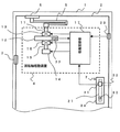
図1は本発明の実施の一形態を示す機能構成を示している。図示されたドアクローザシステムでは、ドアクローザの機能を理解容易とするためアーム5の開閉が回転扉2の開閉と連動する場合について説明する。
【0022】
従って、図1に示されたドアクローザシステムは、扉枠1、回転扉2、蝶番3、回転軸駆動装置4、アーム5、アーム固定具6、および取っ手部7により構成されている。回転軸駆動装置4は、駆動回転軸11、駆動力発生体12、駆動軸クラッチ13、モータ14、駆動力供給体15、モータクラッチ16、および駆動制御部17を備えている。モータ14と駆動力供給体15とでモータ駆動体を形成し、モータ14の回転により、例えばウォームギア機構による駆動力供給体15を直接駆動している。更に、ドアクローザシステムとして取っ手センサ21、限度センサ22、および閉扉センサ23が設けられている。また、取っ手部7は取っ手の握り部31と自動閉扉爪を形成する係止爪32と施錠部33と上下に伸びて握り部31および施錠部33を固定する表裏面の平板34とにより構成されている。
【0023】
扉枠1は壁の出入り口を形成し回転扉2を閉じる際にその閉鎖位置を決める。回転扉2は、閉じる側の面を表面、開く側の面を裏面とし、出入り口の左右の一方、図1の場合は左側、に蝶番3により回動可能に扉枠1に保持される。回転軸駆動装置4は、回転扉2の表面に固定されると共に、回転駆動軸11をアーム5の一端と直結し、駆動力発生体12により駆動力を発生して開いている回転扉2を扉枠1まで閉じる方向に回転駆動軸11を介して押圧する。アーム5は一端を回転扉2の表面に固定される回転軸駆動装置4、他端を扉枠1の上部に固定されるアーム固定具6、それぞれに回動可能に固定され、中間部分にも中心軸を設けて連結し、回転扉2の開閉に応じて二つの固定端を開閉する。
【0024】
また、取っ手部7では、人が取っ手の握り部31を握った際の回転動作または電気的作動により係止爪32の係止を解除し、押すかまたは引くかして回転扉2を開閉する。一方、係止爪32は、回転扉2が閉じる際には自動的に埋没し閉じた後には扉枠1内の係止穴(図示省略)で突出して係止し、回転扉2が開くのを妨げる一方、握り部31の回転動作または電気的作動に連動して埋没する。従って、係止爪32は、握り部31の放置状態で回転扉2の閉扉を確保する一方、握り部31の回転動作または電気的作動と連動して閉扉を解除することができる。すなわち、ユーザによる開扉するための操作がない場合、回転軸駆動装置4とアーム5との構造により回転扉2は扉枠1に密着し閉じられた状態になると共に、係止爪32により閉扉が確保される。
【0025】
駆動回転軸11は、アーム5の一端と中心軸を共有して直結し、駆動力発生体12から駆動軸クラッチ13を介して受ける回転駆動力により、回転扉2を閉じる方向へアーム5を運動させる。
【0026】
駆動力発生体12は、例えば螺旋状ばねのような弾性体により構成され、弾性体の弾性をクローザ駆動力源とし、縮まった状態から伸びる際に生じる押圧力を駆動軸クラッチ13により連結される駆動回転軸11からアーム5に伝達している。従来は、ユーザが開く回転扉2によりばね状の弾性体は縮められてクローザ駆動力が与えられている。しかし本発明では、駆動力発生体12が、モータクラッチ16の励起によりモータ機構に含まれるモータ14と連結してモータ14の駆動を受け、弾性体を縮めている。この弾性体を縮めている間、介在する駆動軸クラッチ13は連結解除されておりアーム5と切り離されている。
【0027】
駆動軸クラッチ13は、駆動回転軸11と駆動力発生体12との間にある電磁クラッチであり、両者を瞬時に連結しまたはその連結を解除する。ここで、駆動軸クラッチ13が励起された連結状態を「オン」とする。
【0028】
モータ機構を形成するモータ14と駆動力供給体15とでは、モータ14が、例えばウォームギア構造の駆動力供給体15により、励起されたモータクラッチ16を介して駆動力発生体12の弾性体を縮める方向に運動してクローザ駆動力を与える。
【0029】
モータクラッチ16は、駆動力発生体12と駆動力供給体15との間にある電磁クラッチであり、駆動制御部17の制御を受けて両者を瞬時に連結しまたは解除する。ここで、モータクラッチ16が励起された連結状態を「オン」とする。
【0030】
駆動制御部17は、例えば各種メモリを有しプログラムで制御される中央処理ユニット(CPU)であり、上述する各構成要素とアクセスしてシステム機能を発揮する。すなわち、取っ手センサ21、限度センサ22、および閉扉センサ23から検知信号を受け、駆動軸クラッチ13、モータ14、およびモータクラッチ16の励起を制御すると共に、図示されていないが取っ手センサタイマを含んでいる。
【0031】
取っ手センサタイマは、動作の安定化を図るため、モータ14が駆動力発生体12を駆動し、例えば螺旋状ばねを最も縮めるまでの最も長い時間をカバーできるだけの一定時間を計測している。従って、開閉扉2が開放状態にある場合、この時限の間、駆動制御部17は取っ手センサの検知情報を無視して、「オン」状態を連続保持させている。
【0032】
駆動制御部17の主要機能はフローチャートを参照して後に説明する。
【0033】
次に、取っ手センサ21は、取っ手部7で複数箇所に設けられ、例えば表裏面に設けられる握り部31それぞれでの握り、および表裏面に設けられる平板34への人体による接触のうちの何れかを検知し、この検知している間を「オン」とする。また、取っ手センサが、人が回転扉2に近接したことを検知するセンサの場合では、この検知の間を「オン」とする。
【0034】
限度センサ22は、駆動力発生体12に備えられ、回転扉2が最大限度まで開いた場合に達した駆動力発生体12の状態を検知して「オン」となる。駆動力発生体12が上述したように螺旋状ばねのような弾性体の場合、最も縮まった状態を「オン」として検出する。実験では、限度センサ22は、駆動力発生体12の下の部分でモータクラッチ16の上部に取付けられた。
【0035】
閉扉センサ23は、扉枠1と回転扉2とで蝶番3の取付け部と対向する側で回転扉2に設けられ、回転扉2が完全に閉じられて扉枠1に接し係止爪32により係止されていることを検知している間を「オン」とする。
【0036】
上記説明では図面を参照して、回転軸駆動装置が回転扉の表面に備えられるとしたが、蝶番をアームとする回転軸駆動装置のように、回転軸駆動装置が扉枠に設けられる場合には、閉扉センサは扉枠側に備えられ、取っ手センサとの接続回路は蝶番を介して接続される。
【0037】
次に、本システムに電源が供給される際の動作手順の一実施例について説明する。ここで、駆動力発生体12は螺旋状ばねで形成されているものとする。
【0038】
上述した構成において、電源が未供給の状態では、駆動軸クラッチ13およびモータクラッチ16は両者共励起がなく、駆動力発生体12の螺旋状ばねは、回転扉2が完全に閉じた場合の状態に対応しており、最も伸びた状態である。この状態では、回転扉2は、駆動力発生体12のクローザ駆動力がアーム5から切離されており、風力にもなびく状態である。
【0039】
従って、回転扉2が閉鎖係止され閉扉センサ23が「オン」の状態で電源の供給が開始された場合とは、電源が「オン」の状態で回転扉2が閉じており閉扉センサ23が「オン」である開扉待ちと同一の状態となるので、特別の動作作用は起こらない。
【0040】
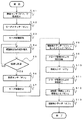
次に、図1に図2を併せ参照して、回転扉2が半開き状態にある場合に電源が供給された際の駆動制御部17における動作手順の一実施例について説明する。この状態では、回転扉2が開いているので、電源が投入された際の閉扉センサ23は「オフ」状態である。
【0041】
閉扉センサ23が「オフ」状態で電源が投入(手順S1)された際に、駆動軸クラッチ13は「オフ」状態にあり、モータクラッチ16が励起されて「オン」(手順S2)となる。従って、モータクラッチ16が駆動力供給体15を介して駆動力発生体12の螺旋状ばねをモータ14と連結するので、モータ14の駆動が開始(手順S3)される。
【0042】
手順S3のモータ14の駆動により駆動力発生体12の螺旋状ばねの縮み程度が増大(手順S4)して、限度に到達(手順S5のYES)した際には限度センサ22がこれを検知して「オン」(手順S6)となる。
【0043】
手順S6における限度センサ22の「オン」により、モータ14の駆動が停止(手順S7)されると共に、駆動軸クラッチ13が「オン」して駆動力発生体12のクローザ駆動力をアーム5に連結する一方、モータクラッチ16を「オフ」(手順S8)して駆動力発生体12からモータ14を切離す。
【0044】
手順S8の駆動軸クラッチ13の「オン」により、駆動力発生体12のクローザ駆動力はアーム5に伝達され、アーム5が回転扉2を閉じる方向へ押し出し、閉扉を開始(手順S9)する。この閉扉の開始は、駆動力発生体12の螺旋状ばねが伸びるので、限度センサ22は「オフ」(手順S10)となる。更に、駆動力発生体12のクローザ駆動力によりアーム5が閉扉を終了(手順S11)するので、閉扉センサ23が「オン」(手順S12)となり、取っ手部7の係止爪32の機能により回転扉2は開くことがない。
【0045】
次いで、図3に図1を併せ参照して閉じた回転扉2を開く駆動制御部17の動作手順について説明する。
【0046】
平常時、電源が供給されている間、上述したように、駆動力発生体12のクローザ駆動力によりアーム5が閉扉を終了するので、閉扉センサ23が「オン」となっており、取っ手部7の係止爪32の機能により回転扉2は閉じられている「閉扉ロック」の状態である。従って、回転扉2は、駆動力発生体12のクローザ駆動力により閉じているので、閉扉センサ23は「オン」(手順S21)であり、駆動軸クラッチ13、モータクラッチ16、およびモータ14の駆動回路は開放されている。
【0047】
この状態で、取っ手センサ21が「オン」(手順S22のYES)となった際には、取っ手部7の係止爪32が埋没して「閉扉ロック」を解放して開扉されるので閉扉センサ22が「オフ」(手順S23)となり、モータクラッチ16およびモータ14の駆動回路は閉じられる。この手順S23の「閉扉ロック」の解放により回転扉2は、駆動力発生体12のクローザ駆動力から切離されているうえ、係止爪32の係止から切り離されるので、開閉自在となる。
【0048】
上記手順S22の「YES」における取っ手センサ21の「オン」により取っ手センサタイマ(図示されていない)が起動(手順S24)する。また、上記手順S22の「YES」により、モータ14が駆動されると共にモータクラッチ16が「オン」(手順S25)となる。この手順S25により、駆動力発生体12の螺旋状ばねがモータ14の駆動を受けて縮み程度が増大(手順S26)する。
【0049】
次いで、螺旋状ばねが縮んで限度に到達する(手順S27のYES)ので、限度センサ22が「オン」(手順S28)となる。この結果、モータ14の駆動は停止(手順S29)する。更に、取っ手センサタイマが時限に到達(手順S30のYES)した以降に、取っ手センサ21が「オフ」(手順S31のYES)となった時点で、駆動軸クラッチ13が「オン」すると共にモータクラッチ16が「オフ」(手順S32)する。
【0050】
取っ手センサタイマが設けられているのは、上記手順S22の「YES」で、取っ手センサ21が「オン」となった以降に回転扉2の開閉自在が原因で、人の取っ手部7への接触が断続して取っ手センサ21の「オン・オフ」が短時間で繰返されること、または取っ手センサ21を「オン」にしたまま回転扉2を無理に閉じることなどが発生した場合でもモータ14の駆動を継続させるためである。取っ手センサタイマは、取っ手センサ21の「オン・オフ」状態を動作手順に無関係とするように、モータ14の最大駆動時間を満たす、例えば15秒間の時限を計測している。
【0051】
すなわち、上記説明では、一旦、取っ手センサが「オン」となった際には、モータ14により螺旋状ばねがもっとも縮んだ状態にされている。このことは、駆動力発生体12が、回転扉2が最高に開いた状態に適用できるように、駆動されていることを意味する。
【0052】
上記手順S32で駆動軸クラッチ13が「オン」しかつモータクラッチ16が「オフ」したことにより、駆動力発生体12の螺旋状ばねは最も縮んだ状態から伸びる動作が生じ、限度センサ22は「オフ」(手順S33)される。回転扉2が限度まで開いた状態では直ちにクローザ駆動力がアーム5に加わる。しかし、半開きの回転扉2に対しては、アーム5が回転扉2の開き程度に対応して開いた位置にあるので、駆動力発生体12の螺旋状ばねは最も縮んだ状態から伸びる動作が生じ、アーム5の半開き状態位置に対応する縮み程度までに達する。
【0053】
このような動作に続いて、駆動力発生体12の螺旋状ばねの駆動力により回転扉2の閉扉が開始(手順S34)される。この結果、駆動制御部17にある取っ手センサタイマは初期化(手順S35)される。この手順S35以降、回転扉2が完全に閉じれば、閉扉センサ23が「オン」となり、開始時点の手順S21の状態に戻る。
【0054】
他方、回転扉2が閉じる前に取っ手センサ21が「オン」となった場合には、駆動軸クラッチ13が「オフ」となって、上記手順S23が実行された状態となり、上記手順S24からの手順が繰り返される。
【0055】
上記説明では、回転軸駆動装置が駆動力発生体から回転駆動軸を介して伝達する駆動力でアームを駆動し回転扉を閉じる方向へ動かしているが、アームを使用せずに回転扉を閉じる回転軸駆動装置をフロアヒンジとして床面または床下に設けることができる。更に、回転軸駆動装置は、壁面もしくは壁内または天井に設けることもできる。床下の場合、回転軸駆動装置を大型化できるので、大型の重い回転扉に適応可能である。
【0056】
すなわち、このような回転軸駆動装置は、回転駆動軸、駆動力発生体、駆動軸クラッチ、モータ、およびモータクラッチを含み、回転駆動軸が回転扉の回転軸と連結し回転駆動軸の回転に応じて回転扉を開閉すると共に、回転駆動軸から伝達する駆動力が回転扉を閉じる方向に動かすこととなる。
【0057】
また、取っ手センサが取っ手部に人が触ったことを検知するとしたが、回転扉に近接した人を、例えば人の体温で検知して取って部の係止爪の係止を解除する構成であってもよい。
【0058】
また、上記説明では、各センサの感知情報をCPUのような装置で受けて機能動作が制御されているが、各センサを、ノンロック型接点を有するスイッチとして電気回路を形成し、上記機能動作を実現することができる。勿論、各センサそれぞれで、検知により駆動される電磁リレーを設け、これら電磁リレーの接点で回路を組むこともできる。この場合、例えば、上述したように閉扉している状態を「オン」としたのに対して「オフ」となる電磁リレーを設けることができる。しかし、以下の説明における各スイッチの「オン・オフ」条件は図面を参照して説明した上述の条件と一致させることとする。
【0059】
すなわち、上記取っ手センサは回転扉を開こうとする人を感知している間を「オン」とする接点ST−1を有する取っ手スイッチSTであるとする。限度センサは駆動力発生体12の螺旋状ばねの最も縮んだ状態を「オン」とする接点SL−1〜3を有する限度スイッチSLであるとする。かつ、閉扉センサは回転扉が完全に閉じて係止爪で係止されている状態を「オン」とする接点SC−1,2を有する閉扉スイッチSCであるとする。更に、電源供給開始の際に動作を確保する電磁リレーとして、限度スイッチSL保持のための接点rsl−1〜3を有する限度スイッチ保持リレーRSLが備えられる。また、感知タイマはタイマの計測開始から時限到達までの間を「オン」とする感知タイマスイッチTTを有している。
【0060】
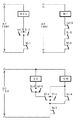
図4は駆動制御部における回路の実施の一形態を示す図である。ここで示される駆動軸クラッチCD、モータクラッチCM、およびモータMTは図1で示される構成であるとする。上述した接点には「オン」条件で電気回路を閉じるメーク接点と電気回路を開くブレーク接点とがある。
【0061】
実験では、リレーRSLは並列されるメーク接点rsl−1およびメーク接点SL−1と直列接続されるブレーク接点SC−1との回路で、また、モータMTはブレーク接点rsl−3,SL−3,SC−3により直列接続される回路でそれぞれAC(交流)100ボルトにより駆動される。駆動軸クラッチCDは並列のメーク接点SL−2,rsl−2、並列のメーク接点ST−1,TT−1、およびブレーク接点SC−2の直列回路で、AC100ボルトからインバータで変換されたDC(直流)12ボルトにより駆動される。モータクラッチCMには並列のメーク接点ST−1,TT−1およびブレーク接点rsl−4に直列のブレーク接点SC−2によりDC12ボルトが供給される。
【0062】
図5は、図4の構成で、上記図2と同様の動作作用を実現するタイムチャートである。
【0063】
電源が供給されていない状態では、全てのスイッチは「オフ」状態である。従って、AC100ボルト電源供給の際には、モータMTがブレーク接点rsl−3,SL−3,SC−3を介して電源を受けて「オン」する。DC12ボルト電源供給の際には、モータクラッチCMがブレーク接点rsl−4,SC−2を介して電源を受け、「オン」する。
【0064】
モータMTおよびモータクラッチCMの「オン」により螺旋状ばねが巻き上げられ縮む。最大限縮んだ時点で限度スイッチSLが「オン」になるので、メーク接点SL−1が回路を閉じて保持リレーRSLが動作する一方、ブレーク接点SL−1が開いてモータMTの駆動を停止する。また、メーク接点SL−2が回路を閉じて駆動軸クラッチCDを「オン」とする。保持リレーRSLの動作はブレーク接点rsl−4が回路を開いてモータクラッチを「オフ」する。
【0065】
駆動軸クラッチCDの「オン」とモータクラッチの「オフ」により螺旋状ばねは駆動回転軸を駆動して閉扉動作を開始する。従って、限度スイッチSLは「オフ」される。閉扉動作が完了した際には閉扉スイッチSCが「オン」するので、ブレーク接点SC−1が回路を開き保持リレーRSLを復旧させると共に、ブレーク接点SC−2が回路を開き駆動軸クラッチCDを「オフ」して、開扉要求の取っ手センサの検知による取っ手スイッチSTの「オン」を待つ。
【0066】
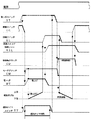
次いで、図6は、図4の構成で、上記図3と同様の動作作用を実現するタイムチャートである。
【0067】
電源が「オン」されてスイッチSTの「オン」を待つ状態では回転扉が閉じられているので、閉扉スイッチSCのみは「オン」状態でブレーク接点SC−1〜SC−3が回路を開いている。従って、保持リレーRSL、モータMT、駆動軸クラッチCD、およびモータクラッチCMの全てが「オフ」状態である。
【0068】
取っ手スイッチSTが「オン」した際には、係止爪の掛止が外れて開扉し、閉扉スイッチSCは「オフ」されるので、ブレーク接点SC−1〜SC−3が閉じる。従って、モータMTがブレーク接点rsl−3,SL−3,SC−3を介して電源を受けて「オン」すると共に、モータクラッチCMがブレーク接点rsl−4,SC−2を介して電源を受け、「オン」する。また、取っ手スイッチSTの「オン」により、感知タイマスイッチTTが「オン」されて感知タイマ時限の計測を開始する。
【0069】
他方、モータMTおよびモータクラッチCMの「オン」により螺旋状ばねが巻き上げられ縮む。最大限縮んだ時点で限度スイッチSLが「オン」になるので、メーク接点SL−1が回路を閉じて保持リレーRSLが動作する一方、ブレーク接点SL−3が開いてモータMTの駆動を停止する。
【0070】
感知タイマの計測が時限に到達した際には、螺旋状ばねの巻上げが完了し、感知タイマスイッチTTが「オフ」されて取っ手センサSTの「オフ」を待つ。
【0071】
この状態で、取っ手スイッチSTが「オフ」になった際には、ブレーク接点ST−1が回路を閉じて駆動軸クラッチCDを「オン」にすると同時にメーク接点ST−1が回路を開いてモータクラッチCMを「オフ」にする。この結果、螺旋状ばねは駆動回転軸を駆動して閉扉動作を開始する。従って、限度スイッチSLは「オフ」される。
【0072】
閉扉動作が完了した際には閉扉スイッチSCが「オン」するので、ブレーク接点SC−1が回路を開き保持リレーRSLを復旧させると共に、ブレーク接点SC−2が回路を開き駆動軸クラッチCDを「オフ」して、開扉要求の取っ手センサの検知による取っ手スイッチSTの「オン」を待つ最初の状態に戻る。
【0073】
上記説明では、実験における供給電圧がAC100ボルトおよびDC12ボルトであるとしたが、他の電源電圧、例えば商用電源のAC100ボルトから変換されたDC24ボルトなどであってもよい。また、停電などの事態を配慮し、DC24ボルトまたはDC12ボルトのバッテリーを予備電源に内蔵し、商用電源から変換するDC駆動であることが望ましい。
【0074】
このように、上記説明では、図示された機能ブロックおよび手順を参照しているが、機能の分離併合による配分または手順の前後入替えなどの変更は上記機能を満たす限り自由であり、上記説明が本発明を限定するものではなく、更に、ドアクローザシステムの全般に適用可能なものである。
【0075】
【発明の効果】
以上説明したように本発明によれば、回転扉が駆動回転軸の駆動力を受けて自動的に回転扉を閉じるドアクローザシステムで、開扉要求を検知する取っ手センサと、取っ手センサが開扉要求を検知した際に、回転扉を閉じる駆動回転軸への駆動力を切り離す駆動軸クラッチとを備えるシステムを提供している。
【0076】
この構成で回転扉の開閉に伴って開閉し、駆動回転軸の駆動力を受けて回転扉を閉じるアームを供える場合、取っ手センサが開扉要求を検知した際に、駆動軸クラッチがアームを回転軸駆動装置から切り離すので、回転扉を閉じるクローザ駆動力も切り離され、回転扉にはいかなる開閉力もかからない。従って、回転扉の重さと蝶番の回転摩擦とのみを開扉の対象とできるので、老人のような非力な人でも容易に軽々と回転扉を開閉することができるという効果が得られる。
【0077】
また、本発明によれば、アームを切離した回転軸駆動装置の駆動力発生体と連結した際に、この駆動力発生体を回転扉が開いた状態に適用できるように、螺旋状ばねの場合では縮める方向に、駆動するモータと、モータが駆動力発生体を駆動する際にモータと駆動力発生体とを連結するモータクラッチとを備えるシステムを提供している。
【0078】
この構成により、取っ手センサから開扉要求の検知が消滅した際には、回転軸駆動装置の駆動力発生体がモータにより回転扉が開いた状態に適用できるように駆動されているので、駆動軸クラッチを連結したのちモータクラッチの連結を解放することにより、駆動力発生体のクローザ駆動力を回転扉に与えて自動的に閉じさせることができる。
【0079】
また、駆動回転軸を介して駆動力発生体のクローザ駆動力を直接回転扉の回転軸に与え、アームを設けないフロアヒンジの場合では、床下に回転軸駆動装置を設置できるので、大型装置による強力な回転軸駆動力が得られる。従って、重量のある大型玄関扉にも適用することができる。
【図面の簡単な説明】
【図1】本発明のシステムにおける機能ブロックおよび正面配置の実施の一形態を示す図である。
【図2】図1の回転扉が半開き状態にある場合に電源が供給される際の、駆動制御部における動作手順の実施の一形態を示すフローチャートである。
【図3】図1の閉じた回転扉を開く際の、駆動制御部における動作手順の実施の一形態を示すフローチャートである。
【図4】本発明の回転軸駆動装置をスイッチ接点により形成する際の電気回路の実施の一形態を示す図である。
【図5】図4において回転扉が半開き状態にある場合に電源が供給される際の、駆動制御部における動作の実施の一形態を示すタイムチャートである。
【図6】図4において閉じた回転扉を開く際の、駆動制御部における動作の実施の一形態を示すタイムチャートである。
【図7】従来のシステムにおける正面配置の一例を示す図である。
【符号の説明】
1 扉枠
2 回転扉
3 蝶番
4 回転軸駆動装置
5 アーム
6 アーム固定具
7 取っ手部
11 駆動回転軸
12 駆動力発生体
13 駆動軸クラッチ
14 モータ
15 駆動力供給体
16 モータクラッチ
17 駆動制御部
21 取っ手センサ
22 限度センサ
23 閉扉センサ
31 握り部
32 係止爪
33 施錠部
34 平板[0001]
BACKGROUND OF THE INVENTION
The present invention relates to a door closer system in which a driving force generator applies a driving force to a rotary drive shaft that connects rotary doors to close the rotary door, and more particularly to a door closer that can reduce pressing force or tensile force when a person opens the rotary door. About the system.
[0002]
[Prior art]
Conventionally, this type of door closer system is applied to, for example, a
[0003]
FIG. 7 illustrates a front view of the revolving
[0004]
The
[0005]
The revolving
[0006]
That is, when the user does not perform an operation for opening the door, the structure of the
[0007]
In another door closer system, for example, there is a cylindrical rotary shaft driving device that automatically closes the rotary door by driving the hinge using the hinge flat plate as an arm and the hinge rotary shaft as a common rotary shaft. This rotary shaft drive device also has a built-in drive generator by a spiral spring, for example. Further, as a rotary shaft drive device for driving the rotary drive shaft, the rotary drive shaft is buried in the floor, the rotary drive shaft is connected to the rotary shaft of the rotary door, and the rotary door is opened and closed in accordance with the rotation of the rotary drive shaft. There is a so-called floor hinge that moves the revolving door in the closing direction.
[0008]
[Problems to be solved by the invention]
In the conventional door closer system described above, there is a problem in that it is difficult and difficult for an inferior person such as an elderly person to open the revolving door.
[0009]
The reason is that the drive generator built in the rotary shaft drive device provided as a door closer presses and closes the revolving door. Therefore, in order to open the revolving door, the revolving door is pushed or pulled with a force superior to this pressing force. This is because it is necessary to open the revolving door by human power in order to apply the pressing force of the drive generator.
[0010]
The subject of this invention is providing the door closer system which can open and close the revolving door provided with the door closer, solving such a problem and applying almost no force.
[0011]
[Means for Solving the Problems]
The door closer system according to the present invention is a revolving door. Axis of rotation It is an object to be able to open and close the revolving door with almost no force applied despite the provision of a driving force generator that applies a driving force to the revolving door to close the revolving door. For this reason, the door closer system includes an opening request sensor that detects an opening request of the rotating door, a rotation driving unit that is connected to the rotating door and applies a driving force to the rotating shaft, and at least detection of the opening request by the opening request sensor. A drive control unit that releases the connection between the rotary door and the rotary drive unit until a predetermined condition occurs; The
[0012]
That is, the door closer system according to the present invention includes a motor mechanism that applies a driving force generator to the door for closing doors, a drive shaft clutch that connects the rotary drive shaft and the drive force generator, and a drive force generator. The motor clutch which connects between a body and a motor mechanism, the handle sensor which detects the opening request | requirement of a rotary door, and the drive control part which controls these components and exhibits a function are provided.
[0013]
The drive control unit closes and locks the rotary door when receiving power supply and releases the connection of the drive shaft clutch. When detecting the opening request of the handle sensor, the drive control unit releases the lock and rotates. While allowing the shaft to move freely, the motor mechanism is started and the motor clutch is connected to drive the driving force generator so that the rotating door is open. Further, when the opening request detection of the handle sensor disappears, the drive control unit stops the operation of the motor mechanism and releases the connection of the motor clutch to disconnect the motor mechanism from the driving force generator, while the drive shaft clutch Are connected to transmit the driving force of the driving force generator to the rotary drive shaft, and the pressing force is applied in the direction of closing the rotary door.
[0014]
In the configuration described above, when the opening request of the handle sensor is detected and turned “on”, the driving force of the driving force generator in the direction of closing the rotary door by the driving shaft clutch is separated from the rotating driving shaft. Only the weight of the revolving door and the rotational friction of the hinge are required to open the door, and the user needs little force when opening the revolving door. With this structure, the opening and closing of the revolving door cannot be fixed. Therefore, in order to stabilize the “on” information of the handle sensor, it is desirable that the drive control unit is provided with a handle sensor timer, and the handle sensor timer ignores the “on / off” information of the handle sensor for a certain period of time.
[0015]
In the system according to the present invention, it is preferable that the system further includes a limit sensor for detecting a limit state when the rotary door is most opened by the driving force generator. When the limit sensor is provided, the drive control unit stops the operation of the motor mechanism when the limit sensor detects the limit state when starting the operation of the motor mechanism and connecting the motor clutch to drive the driving force generator. The detection disappearance of the handle sensor can be monitored. As a result, when the detection of the handle sensor is extinguished, the drive control unit immediately releases the connection of the motor clutch and connects the drive shaft clutch to transmit the drive force of the drive force generator to the rotary drive shaft and close the rotary door. A pressing force can be applied in the direction. At this time, since the driving force generator corresponds to a position corresponding to the rotational drive shaft position equivalent to the degree of opening of the rotary door, stable operation and reliable closing of the rotary door can be executed each time the handle sensor is detected.
[0016]
Further, in the system, it is desirable to provide a closing sensor that detects that the revolving door is closed. When the power supply is supplied, the drive control unit detects that the door is closed and the drive shaft clutch is not connected. The drive control unit starts driving the motor mechanism and connects the motor clutch until the limit sensor detects the limit state. Since the force generator is driven, a stable operation can be executed at the start of the operation of the system.
[0017]
The drive control unit preferably further includes a timer that is activated when the handle sensor detects the opening request and ignores the detection state of the handle sensor until a predetermined time has elapsed. By further providing a timer, stable operation can be expected against repeated intermittent sensing of the handle sensor.
[0018]
In addition, it has an arm that directly connects between the revolving door and the door frame and opens and closes according to the opening and closing of the revolving door, and the rotation drive shaft is fixed to one end of the arm and opens and closes the arm according to the rotation. The invention can be applied. Further, the rotary drive shaft is connected to the rotary shaft of the rotary door without an arm, so that the rotary door is opened and closed according to the rotation of the rotary drive shaft and closed in the direction to be closed by the transmitted driving force. The present invention can also be applied to a moving floor hinge. Needless to say, the drive device for the rotary drive shaft may be arranged not only under the floor but also on the wall or ceiling.
[0019]
Furthermore, the handle sensor detects when the human body touches the handle of the revolving door, when the human body approaches the revolving door, or when the handle of the revolving door rotates, and outputs it as a request to open the revolving door. Also good.
[0020]
DETAILED DESCRIPTION OF THE INVENTION
Next, embodiments of the present invention will be described with reference to the drawings.
[0021]
FIG. 1 shows a functional configuration showing an embodiment of the present invention. In the illustrated door closer system, the case where the opening and closing of the
[0022]
Therefore, the door closer system shown in FIG. 1 includes the
[0023]
The
[0024]
Further, in the
[0025]
The
[0026]
The driving
[0027]
The
[0028]
In the motor 14 and the driving
[0029]
The motor clutch 16 is an electromagnetic clutch between the driving
[0030]
The drive control unit 17 is a central processing unit (CPU) that has various memories and is controlled by a program, for example, and accesses each of the above-described components to exhibit a system function. That is, it receives detection signals from the
[0031]
In order to stabilize the operation of the handle sensor timer, the motor 14 drives the driving
[0032]
The main functions of the drive control unit 17 will be described later with reference to a flowchart.
[0033]
Next, the
[0034]
The
[0035]
The
[0036]
In the above description, with reference to the drawings, the rotary shaft drive device is provided on the surface of the rotary door. However, when the rotary shaft drive device is provided on the door frame like the rotary shaft drive device having a hinge as an arm. The door closing sensor is provided on the door frame side, and the connection circuit with the handle sensor is connected via a hinge.
[0037]
Next, an example of an operation procedure when power is supplied to the system will be described. Here, it is assumed that the driving
[0038]
In the configuration described above, when the power is not supplied, neither the drive shaft clutch 13 nor the motor clutch 16 is excited, and the helical spring of the
[0039]
Therefore, when the supply of power is started when the revolving
[0040]
Next, an example of an operation procedure in the drive control unit 17 when power is supplied when the
[0041]
When the power is turned on in the “off” state of the door closing sensor 23 (procedure S1), the
[0042]
When the degree of contraction of the helical spring of the driving
[0043]
When the
[0044]
When the
[0045]
Next, the operation procedure of the drive control unit 17 that opens the closed revolving
[0046]
During normal times, while the power is supplied, as described above, the closing force of the driving
[0047]
In this state, when the
[0048]
The handle sensor timer (not shown) is activated (procedure S24) by turning the
[0049]
Next, since the spiral spring contracts and reaches the limit (YES in step S27), the
[0050]
The handle sensor timer is provided in the case of “YES” in the above step S22, and after the
[0051]
That is, in the above description, once the handle sensor is turned “ON”, the helical spring is most contracted by the motor 14. This means that the driving
[0052]
When the
[0053]
Subsequent to this operation, the closing of the revolving
[0054]
On the other hand, when the
[0055]
In the above description, the rotary shaft driving device drives the arm with the driving force transmitted from the driving force generator via the rotary driving shaft to move the rotary door in the closing direction, but the rotary door is closed without using the arm. The rotary shaft driving device can be provided as a floor hinge on the floor surface or under the floor. Further, the rotary shaft driving device can be provided on the wall surface or in the wall or on the ceiling. In the case of under the floor, the rotary shaft driving device can be enlarged, and thus can be applied to a large heavy rotary door.
[0056]
That is, such a rotary shaft drive device includes a rotary drive shaft, a driving force generator, a drive shaft clutch, a motor, and a motor clutch. The rotary drive shaft is connected to the rotary shaft of the rotary door to rotate the rotary drive shaft. Accordingly, the rotary door is opened and closed, and the driving force transmitted from the rotary drive shaft moves in the direction of closing the rotary door.
[0057]
In addition, although the handle sensor detects that a person has touched the handle part, the person close to the revolving door is detected based on, for example, the body temperature of the person, and the locking claw of the part is released. There may be.
[0058]
Further, in the above description, the sensing operation information of each sensor is received by a device such as a CPU, and the functional operation is controlled. However, the electric circuit is formed by using each sensor as a switch having a non-locking type contact. Can be realized. Of course, each sensor can be provided with an electromagnetic relay driven by detection, and a circuit can be formed by the contact of these electromagnetic relays. In this case, for example, it is possible to provide an electromagnetic relay that is turned “off” while the door is closed as described above. However, the “on / off” condition of each switch in the following description is made to coincide with the above-described condition described with reference to the drawings.
[0059]
That is, it is assumed that the handle sensor is a handle switch ST having a contact ST-1 that is turned on while a person who is opening a revolving door is being sensed. It is assumed that the limit sensor is a limit switch SL having contacts SL-1 to SL that turn on the most contracted state of the helical spring of the driving
[0060]
FIG. 4 is a diagram showing an embodiment of a circuit in the drive control unit. The drive shaft clutch CD, the motor clutch CM, and the motor MT shown here are assumed to have the configuration shown in FIG. The contacts described above include a make contact that closes the electrical circuit under an “on” condition and a break contact that opens the electrical circuit.
[0061]
In the experiment, the relay RSL is a circuit with a make contact rsl-1 and a break contact SC-1 connected in series with the make contact SL-1, and the motor MT is a break contact rsl-3, SL-3, The circuits connected in series by SC-3 are each driven by AC (alternating current) 100 volts. The drive shaft clutch CD is a series circuit of parallel make contacts SL-2 and rsl-2, parallel make contacts ST-1 and TT-1, and break contact SC-2. DC) Driven by 12 volts.
[0062]
FIG. 5 is a time chart for realizing the same operation and action as in FIG. 2 with the configuration of FIG.
[0063]
In the absence of power, all switches are in the “off” state. Therefore, when AC 100 volt power is supplied, the motor MT receives the power via the break contacts rsl-3, SL-3, and SC-3 and turns on. When
[0064]
When the motor MT and the motor clutch CM are “on”, the spiral spring is wound up and contracted. Since the limit switch SL is turned “ON” when it is fully contracted, the make contact SL-1 closes the circuit and the holding relay RSL operates, while the break contact SL-1 opens to stop the driving of the motor MT. . Further, the make contact SL-2 closes the circuit to turn the drive shaft clutch CD “on”. The operation of the holding relay RSL causes the break contact rsl-4 to open the circuit and "turn off" the motor clutch.
[0065]
When the drive shaft clutch CD is “on” and the motor clutch is “off”, the spiral spring drives the drive rotation shaft to start the door closing operation. Therefore, the limit switch SL is “off”. When the closing operation is completed, the closing switch SC is turned on, so that the break contact SC-1 opens the circuit and restores the holding relay RSL, and the break contact SC-2 opens the circuit and opens the drive shaft clutch CD. “OFF”, and waits for “ON” of the handle switch ST by the detection of the handle sensor of the door opening request.
[0066]
Next, FIG. 6 is a time chart for realizing the same operation and action as in FIG. 3 with the configuration of FIG.
[0067]
Since the revolving door is closed when the power is turned on and waiting for the switch ST to be turned on, only the door closing switch SC is in the on state and the break contacts SC-1 to SC-3 open the circuit. Yes. Accordingly, the holding relay RSL, the motor MT, the drive shaft clutch CD, and the motor clutch CM are all in the “off” state.
[0068]
When the handle switch ST is turned “ON”, the latching claw is released and the door is opened, and the door closing switch SC is turned “OFF”, so that the break contacts SC-1 to SC-3 are closed. Therefore, the motor MT receives power via the break contacts rsl-3, SL-3, SC-3 and is turned “ON”, and the motor clutch CM receives power via the break contacts rsl-4, SC-2. , “Turn on”. In addition, the sensing timer switch TT is turned on by turning on the handle switch ST, and measurement of the sensing timer time period is started.
[0069]
On the other hand, when the motor MT and the motor clutch CM are “on”, the spiral spring is wound up and contracted. Since the limit switch SL is turned “ON” when it is fully contracted, the make contact SL-1 closes the circuit and the holding relay RSL operates, while the break contact SL-3 opens to stop the driving of the motor MT. .
[0070]
When the measurement of the sensing timer reaches the time limit, the winding of the spiral spring is completed, the sensing timer switch TT is “off” and waits for the handle sensor ST to be “off”.
[0071]
In this state, when the handle switch ST is turned off, the break contact ST-1 closes the circuit and the drive shaft clutch CD is turned on, and at the same time, the make contact ST-1 opens the circuit to open the motor. Turn off the clutch CM. As a result, the helical spring starts the door closing operation by driving the drive rotary shaft. Therefore, the limit switch SL is “off”.
[0072]
When the closing operation is completed, the closing switch SC is turned on, so that the break contact SC-1 opens the circuit and restores the holding relay RSL, and the break contact SC-2 opens the circuit and opens the drive shaft clutch CD. “OFF” to return to the initial state of waiting for “ON” of the handle switch ST by the detection of the handle sensor for opening the door.
[0073]
In the above description, the supply voltage in the experiment is assumed to be AC 100 volts and
[0074]
As described above, the functional blocks and procedures shown in the above description are referred to in the above description. However, changes such as distribution by function separation and merging or replacement of the procedures before and after are free as long as the above functions are satisfied. The invention is not limited, and can be applied to all door closer systems.
[0075]
【The invention's effect】
As described above, according to the present invention, in the door closer system in which the rotary door receives the driving force of the drive rotary shaft and automatically closes the rotary door, the handle sensor for detecting the door opening request and the handle sensor for the door opening request And a drive shaft clutch that disconnects the drive force applied to the drive rotary shaft that closes the rotary door when the rotary door is detected.
[0076]
With this configuration, when the arm opens and closes with the opening and closing of the revolving door and receives the driving force of the drive revolving shaft, and provides the arm that closes the revolving door, the drive shaft clutch rotates the arm when the handle sensor detects a door opening request. Since it is separated from the shaft driving device, the closer driving force for closing the revolving door is also separated, and no opening / closing force is applied to the revolving door. Therefore, since only the weight of the revolving door and the rotational friction of the hinge can be targeted for opening, an effect is obtained that the revolving door can be easily opened and closed even by a powerless person such as an elderly person.
[0077]
In addition, according to the present invention, in the case of a spiral spring, when connected to a driving force generator of a rotary shaft driving device with an arm separated, the driving force generator can be applied to a state where the rotary door is open. Then, a system including a motor to be driven in a contracting direction and a motor clutch that couples the motor and the driving force generator when the motor drives the driving force generator is provided.
[0078]
With this configuration, when the detection of the door opening request disappears from the handle sensor, the driving force generator of the rotating shaft driving device is driven so that it can be applied to the state where the rotating door is opened by the motor. By releasing the connection of the motor clutch after connecting the clutch, the closer driving force of the driving force generator can be applied to the revolving door and automatically closed.
[0079]
In addition, in the case of a floor hinge that does not have an arm, the closer driving force of the driving force generator is directly applied to the rotary shaft of the rotary door via the drive rotary shaft, so that the rotary shaft drive device can be installed under the floor. A powerful rotating shaft driving force can be obtained. Therefore, the present invention can be applied to a large entrance door having a heavy weight.
[Brief description of the drawings]
FIG. 1 is a diagram showing an embodiment of functional blocks and a front layout in a system of the present invention.
2 is a flowchart showing an embodiment of an operation procedure in a drive control unit when power is supplied when the rotary door of FIG. 1 is in a half-open state.
FIG. 3 is a flowchart showing an embodiment of an operation procedure in a drive control unit when the closed revolving door of FIG. 1 is opened.
FIG. 4 is a view showing an embodiment of an electric circuit when the rotary shaft driving device of the present invention is formed by a switch contact.
5 is a time chart showing an embodiment of an operation in the drive control unit when power is supplied when the rotary door is in a half-open state in FIG. 4;
6 is a time chart showing one embodiment of the operation in the drive control unit when the closed revolving door is opened in FIG. 4. FIG.
FIG. 7 is a diagram showing an example of a front arrangement in a conventional system.
[Explanation of symbols]
1 Door frame
2 Revolving door
3 Hinge
4 Rotating shaft drive
5 arm
6 Arm fixture
7 Handle part
11 Drive shaft
12 Driving force generator
13 Drive shaft clutch
14 Motor
15 Driving force supplier
16 Motor clutch
17 Drive controller
21 Handle sensor
22 Limit sensor
23 Door closing sensor
31 grip
32 Locking claws
33 Locking part
34 flat plate
Claims (12)
Priority Applications (1)
| Application Number | Priority Date | Filing Date | Title |
|---|---|---|---|
| JP2003034584A JP3746767B2 (en) | 2003-02-13 | 2003-02-13 | Door closer system |
Applications Claiming Priority (1)
| Application Number | Priority Date | Filing Date | Title |
|---|---|---|---|
| JP2003034584A JP3746767B2 (en) | 2003-02-13 | 2003-02-13 | Door closer system |
Publications (3)
| Publication Number | Publication Date |
|---|---|
| JP2004244882A JP2004244882A (en) | 2004-09-02 |
| JP2004244882A5 JP2004244882A5 (en) | 2005-10-20 |
| JP3746767B2 true JP3746767B2 (en) | 2006-02-15 |
Family
ID=33020215
Family Applications (1)
| Application Number | Title | Priority Date | Filing Date |
|---|---|---|---|
| JP2003034584A Expired - Fee Related JP3746767B2 (en) | 2003-02-13 | 2003-02-13 | Door closer system |
Country Status (1)
| Country | Link |
|---|---|
| JP (1) | JP3746767B2 (en) |
Families Citing this family (10)
| Publication number | Priority date | Publication date | Assignee | Title |
|---|---|---|---|---|
| US8225458B1 (en) | 2001-07-13 | 2012-07-24 | Hoffberg Steven M | Intelligent door restraint |
| US7316096B2 (en) | 2004-06-30 | 2008-01-08 | Yale Security Inc. | Door operator |
| US7795746B2 (en) * | 2008-05-01 | 2010-09-14 | Robert Bosch Gmbh | Apparatus and method for generating power for a low current device |
| KR101032484B1 (en) | 2009-01-21 | 2011-05-04 | 탑테크주식회사 | Motor-driven active windows and doors having semiautomatic operation mode |
| US8407937B2 (en) | 2009-10-22 | 2013-04-02 | Yale Security Inc. | Door operator |
| US9163446B2 (en) | 2010-03-17 | 2015-10-20 | Yale Security Inc. | Door control apparatus |
| MX2019009664A (en) * | 2017-02-13 | 2020-01-30 | Webco Industries Inc | Work hardened welds and methods for same. |
| US11339900B2 (en) | 2017-02-13 | 2022-05-24 | Webco Industries, Inc. | Work hardened welds and methods for same |
| KR101971956B1 (en) * | 2018-05-30 | 2019-04-25 | 최용환 | Assistant apparatus for opennig of swing-type door |
| CN110656833B (en) * | 2018-06-29 | 2022-01-07 | 比亚迪股份有限公司 | Door clutch, door and have its vehicle |
-
2003
- 2003-02-13 JP JP2003034584A patent/JP3746767B2/en not_active Expired - Fee Related
Also Published As
| Publication number | Publication date |
|---|---|
| JP2004244882A (en) | 2004-09-02 |
Similar Documents
| Publication | Publication Date | Title |
|---|---|---|
| JP3746767B2 (en) | Door closer system | |
| US6967587B2 (en) | Hands-free door opener and method | |
| US5910075A (en) | Portable remote-controlled door closer | |
| US20020092237A1 (en) | Device for controlling a door operator | |
| JP2010522295A (en) | Multi-door lock using braking resistance of DC motor | |
| CA2452003C (en) | Remote release for a movable barrier arrangement | |
| JP3435102B2 (en) | Electric / manual folding door | |
| US7627986B2 (en) | Driving device and door closer | |
| JPH09164296A (en) | Power unit for washing machine wherein door opening/closing device is provided | |
| KR20070052630A (en) | Automatic door system for apartment house having the interface with digital door lock | |
| JP2007146586A (en) | Electric lock controller | |
| JP2004293151A (en) | Electronic locking device | |
| JP4632436B2 (en) | Vehicle door latch device | |
| WO2006114026A1 (en) | Door with monitor | |
| JP4224392B2 (en) | Automatic door device for toilet | |
| JP4359994B2 (en) | Opening and closing body control device | |
| CN212743733U (en) | Automatic control system of electric sliding door | |
| JPH0533675Y2 (en) | ||
| JP2003339576A (en) | Automatic opening/closing apparatus for toilet seat and toilet cover | |
| JP2864446B2 (en) | Automatic closing device for sliding door | |
| US20070157518A1 (en) | Power-operated door opening and closing system | |
| JP2003214042A (en) | Motor-driven and manual folding door | |
| JP2005290760A (en) | Starting device for automatic door | |
| JP2002138753A (en) | Sliding door device | |
| GB2286012A (en) | Door closing device |
Legal Events
| Date | Code | Title | Description |
|---|---|---|---|
| A621 | Written request for application examination |
Free format text: JAPANESE INTERMEDIATE CODE: A621 Effective date: 20050520 |
|
| A521 | Written amendment |
Free format text: JAPANESE INTERMEDIATE CODE: A523 Effective date: 20050617 |
|
| A871 | Explanation of circumstances concerning accelerated examination |
Free format text: JAPANESE INTERMEDIATE CODE: A871 Effective date: 20050617 |
|
| A975 | Report on accelerated examination |
Free format text: JAPANESE INTERMEDIATE CODE: A971005 Effective date: 20050713 |
|
| A131 | Notification of reasons for refusal |
Free format text: JAPANESE INTERMEDIATE CODE: A131 Effective date: 20050720 |
|
| A521 | Written amendment |
Free format text: JAPANESE INTERMEDIATE CODE: A523 Effective date: 20050729 |
|
| TRDD | Decision of grant or rejection written | ||
| A01 | Written decision to grant a patent or to grant a registration (utility model) |
Free format text: JAPANESE INTERMEDIATE CODE: A01 Effective date: 20051005 |
|
| R150 | Certificate of patent or registration of utility model |
Free format text: JAPANESE INTERMEDIATE CODE: R150 |
|
| FPAY | Renewal fee payment (event date is renewal date of database) |
Free format text: PAYMENT UNTIL: 20091202 Year of fee payment: 4 |
|
| FPAY | Renewal fee payment (event date is renewal date of database) |
Free format text: PAYMENT UNTIL: 20091202 Year of fee payment: 4 |
|
| FPAY | Renewal fee payment (event date is renewal date of database) |
Free format text: PAYMENT UNTIL: 20101202 Year of fee payment: 5 |
|
| FPAY | Renewal fee payment (event date is renewal date of database) |
Free format text: PAYMENT UNTIL: 20101202 Year of fee payment: 5 |
|
| FPAY | Renewal fee payment (event date is renewal date of database) |
Free format text: PAYMENT UNTIL: 20111202 Year of fee payment: 6 |
|
| FPAY | Renewal fee payment (event date is renewal date of database) |
Free format text: PAYMENT UNTIL: 20111202 Year of fee payment: 6 |
|
| FPAY | Renewal fee payment (event date is renewal date of database) |
Free format text: PAYMENT UNTIL: 20121202 Year of fee payment: 7 |
|
| FPAY | Renewal fee payment (event date is renewal date of database) |
Free format text: PAYMENT UNTIL: 20131202 Year of fee payment: 8 |
|
| R250 | Receipt of annual fees |
Free format text: JAPANESE INTERMEDIATE CODE: R250 |
|
| R250 | Receipt of annual fees |
Free format text: JAPANESE INTERMEDIATE CODE: R250 |
|
| LAPS | Cancellation because of no payment of annual fees |