JP3744788B2 - Sealed battery and manufacturing method thereof - Google Patents
Sealed battery and manufacturing method thereof Download PDFInfo
- Publication number
- JP3744788B2 JP3744788B2 JP2000333051A JP2000333051A JP3744788B2 JP 3744788 B2 JP3744788 B2 JP 3744788B2 JP 2000333051 A JP2000333051 A JP 2000333051A JP 2000333051 A JP2000333051 A JP 2000333051A JP 3744788 B2 JP3744788 B2 JP 3744788B2
- Authority
- JP
- Japan
- Prior art keywords
- reinforcing member
- opening
- fixed
- electrode plate
- battery
- Prior art date
- Legal status (The legal status is an assumption and is not a legal conclusion. Google has not performed a legal analysis and makes no representation as to the accuracy of the status listed.)
- Expired - Fee Related
Links
Images


Classifications
-
- Y—GENERAL TAGGING OF NEW TECHNOLOGICAL DEVELOPMENTS; GENERAL TAGGING OF CROSS-SECTIONAL TECHNOLOGIES SPANNING OVER SEVERAL SECTIONS OF THE IPC; TECHNICAL SUBJECTS COVERED BY FORMER USPC CROSS-REFERENCE ART COLLECTIONS [XRACs] AND DIGESTS
- Y02—TECHNOLOGIES OR APPLICATIONS FOR MITIGATION OR ADAPTATION AGAINST CLIMATE CHANGE
- Y02E—REDUCTION OF GREENHOUSE GAS [GHG] EMISSIONS, RELATED TO ENERGY GENERATION, TRANSMISSION OR DISTRIBUTION
- Y02E60/00—Enabling technologies; Technologies with a potential or indirect contribution to GHG emissions mitigation
- Y02E60/10—Energy storage using batteries
Landscapes
- Sealing Battery Cases Or Jackets (AREA)
Description
【0001】
【発明の属する技術分野】
本発明は、外装缶の開口部をカシメ加工して封口体を気密に固定している密閉電池に関する。
【0002】
【従来の技術】
密閉電池は、底を塞いでいる筒状の外装缶に、電極体と電解液を充填した後、外装缶の開口部を封口体で気密に閉塞して製造される。封口体で外装缶を密閉する構造は、カシメ加工によって、封口体と外装缶との間にゴム状弾性体のガスケットを挟着して気密に密閉する。この構造の従来電池は、図1に示すように、以下の工程で製造される。
【0003】
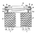
(1) 底を閉塞している外装缶2に、正極板1Aと負極板1Bをセパレータ1Cを介して積層して捲回している電極体1を挿入する。電極体1を入れた後、電極体1上面に絶縁セパレータ9を入れる。
(2) 外装缶2を外周面から溝入れ加工して周壁7を設ける。周壁7は、電極体1と封口体3との境界に設けられて、封口体3が外装缶2に押し込まれるのを阻止するストッパの役目をする。
(3) 外装缶2に電解液を注入して電極体1に浸透させる。
(4) 電極体1に接続しているリード8を、スポット溶接して封口体3に接続する。
(5) 封口体3を外装缶2の開口部にセットした後、外装缶2の開口縁を内側にL字状に折曲し、L字折曲部6と周壁7とで封口体3を挟着して固定する。この状態で封口体3は、ガスケット4を介して挟着される。ガスケット4は、封口体3を気密に固定すると共に、封口体3と外装缶2を絶縁する。したがって、ガスケット4にはゴム状弾性体である絶縁材が使用される。
(6) 最後に、L字折曲部6を上からプレスして、L字折曲部6と周壁7とでガスケット4を確実に挟着して気密な状態とする。
【0004】
【発明が解決しようとする課題】
カシメ加工で封口体を外装缶に固定する電池は、以上の工程で製造されるが、近年、電池重量の軽量化と、高容量化に対する要望がますます大きくなっている。このことを実現するために、外装缶をできるかぎり薄くすることが要求される。ただ、外装缶を薄い金属板で製作すると、封口体を挟着しているL字折曲部が薄くなって強度が低下し、気密性が低下して液漏れの原因となる。
【0005】
この欠点を解消するために、外装缶を開口縁に沿って厚くする電池が開発されている(特開平4−296444号、特開2000−30673号)。この構造の電池は、開口部の強度を向上できる特長はあるが、外装缶の製造が極めて難しくなり、さらに製造コストも相当に高くなる欠点がある。さらに、この構造は、実際の製造工程において以下の(1)と(2)の弊害もある。
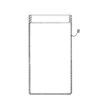
(1) 図2に示すように、外装缶2の開口部を、ケース内側に突出するように厚くすると、外装缶2に電極体1を入れるときに、内側に突出している部分が邪魔になるので、太い電極体を入れることができなくなる。このため外装缶を薄くしても電池の容量を大きくできなくなる。
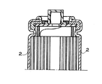
(2) 図3に示すように、外装缶2の開口部を、ケース外側に突出するように厚くすると、組立工程において、外装缶2を横に並べて供給するためにコンベア11上に整列させるときに、隣接する外装缶2同士が外側に厚く突出した部分で接触し、開口部が傾いてしまう欠点がある。この状態は、多数の外装缶をコンベアに並べて正常に移送できなくする。
【0006】
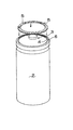
このような欠点を解消する密閉電池として、図4に示す電池が開発されている(特開平9−92236号)。この図の電池は、外装缶2の開口縁を外側に折り返して2枚重ね構造とする。ただ、この構造は、外装缶2と同じ材料を折曲するので、強度増強に限界がある。さらに困ったことに、外装缶2の開口縁をこの形状に折曲すると、金属材料が破断して不良品となって歩留が低下する欠点もある。
【0007】
本発明は、さらにこのような欠点を解決することを目的に開発されたものである。本発明の重要な目的は、外装缶が封口体を充分な強度で固定できる密閉電池とその製造方法を提供することにある。
【0008】
【課題を解決するための手段】
本発明の密閉電池は、正極板1Aと負極板1Bとの間にセパレータ1Cを配設している電極体1と、この電極体1を収容している外装缶2と、この外装缶2の開口部にカシメ加工で気密に固定されている封口体3とを備える。さらに、密閉電池は、外装缶2の開口部に沿って、外装缶2とは別部品である補強部材5を固定している。
【0009】
円筒型電池である密閉電池は、補強部材5を円形リングとすることができる。さらに、角型電池である密閉電池は、補強部材5を角型リングとすることができる。
【0010】
さらに、本発明の密閉電池は、カシメ加工で内側に折曲されたL字折曲部の上面に外装缶の開口部を補強する補強部材5を固定している。
【0011】
さらに、本発明の密閉電池は、補強部材5の横断面形状を溝型として、この補強部材5の溝5A内に外装缶開口縁を嵌入して補強部材5を固定することができる。補強部材5の横断面形状を溝型とする密閉電池は、外装缶2の開口縁に、薄く形成して嵌入部2aを設けて、この嵌入部2aを補強部材5の溝5Aに嵌入することができる。この密閉電池は、補強部材5の溝幅外寸を外装缶2の厚さと同じにすることができる。さらに、溝型の補強部材5は、溝5Aに外装缶2の開口縁を嵌入し、溝5Aで開口縁を挟着して補強部材5を外装缶に固定し、あるいは、補強部材5を外装缶2に溶接して固定することができる。
【0012】
さらに、本発明の密閉電池は、補強部材5の横断面形状をL字状として、この補強部材5の切欠部5Bに外装缶2の開口縁を嵌合させて補強部材5を固定することもできる。
【0013】
本発明の密閉電池の製造方法は、正極板1Aと負極板1Bとの間にセパレータ1Cを配設している電極体1と、電解液とを外装缶2に入れた後、外装缶2の開口部をカシメ加工して封口体3を気密に固定する。さらに、密閉電池の製造方法は、カシメ加工した外装缶2の開口部に沿って補強部材5を固定して補強する。
【0014】
補強部材5は、外装缶2の開口部を折曲してL字折曲部6とした後、このL字折曲部6の上面に溶接して固定することかできる。
【0015】
さらに、本発明の密閉電池の製造方法は、電極体1を入れた外装缶2の開口縁に補強部材5を連結し、補強部材5を連結している外装缶2をカシメ加工して封口体3を固定することができる。
【0016】
補強部材5には、横断面形状を溝型とする溝型補強部材5を使用し、補強部材5の溝5Aに外装缶2の開口縁を入れてカシメ加工することができる。さらに、補強部材5には、横断面形状をL字状とする補強部材5を使用し、補強部材5の切欠部5Bに外装缶2の開口縁を嵌合させてカシメ加工することもできる。
【0017】
【発明の実施の形態】
以下、本発明の実施例を図面に基づいて説明する。ただし、以下に示す実施例は、本発明の技術思想を具体化するための密閉電池とその製造方法を例示するものであって、本発明は電池とその製造方法を以下に特定しない。
【0018】
さらに、この明細書は、特許請求の範囲を理解しやすいように、実施例に示される部材に対応する番号を、「特許請求の範囲の欄」、および「課題を解決するための手段の欄」に示される部材に付記している。ただ、特許請求の範囲に示される部材を、実施例の部材に特定するものでは決してない。
【0019】
図5ないし図7に示す電池は、正極板1Aと負極板1Bとの間にセパレータ1Cを配設している電極体1と、この電極体1を収容している外装缶2と、この外装缶2の開口部をガスケット4を介して気密に閉塞している封口体3とを備える。この電池は、外装缶2をカシメ加工して封口体3を固定している。この図の電池は、ニッケル−水素電池、ニッケル−カドミウム電池、リチウムイオン二次電池等の二次電池である。
【0020】
電池がニッケル−水素電池の場合、負極板には、芯体に水素吸蔵合金を主体とした活物質を塗布した極板を使用し、正極板には、ニッケルの芯体に、スラリー状の水酸化ニッケルを主体とした活物質を含浸して圧延した極板を使用する。正極板と負極板を、ポリプロピレン製不織布からなるセパレータを介して積層して捲回して電極体とする。電解液には、水酸化カリウム系電解液を使用する。
【0021】
電池がニッケル−カドミウム電池の場合、負極板には、極板芯体に酸化カドミウムを主成分としているペースト活物質を充填した帯状の非焼結式負極板を使用し、正極板には、ニッケルの芯体に、スラリー状の水酸化ニッケルを主体とした活物質を含浸して圧延した極板を使用する。ただ、極板は、焼結式の製法で製造することもできる。この極板は、有機増粘剤を含有するスラリを塗着した有孔薄鋼板を還元雰囲気中において焼結したニッケル多孔質焼結基板に、化学含浸あるいは電解含浸によって、カドミウムを充填して負極板とし、あるいは、ニッケルを充填して正極板とする。正極板と負極板を、ポリプロピレン製不織布からなるセパレータを介して積層して捲回して電極体とする。電解液には、水酸化カリウムを主成分とする電解液を使用する。
【0022】
電池がリチウムイオン二次電池の場合、正極板には、リチウム含有複合酸化物である正極活物質、たとえば、LiCoO2を主成分とする正極スラリーを芯体に塗布して圧延した極板を使用し、負極板には、リチウムイオンを吸蔵・放出する炭素質材料である負極活物質、たとえば、天然黒鉛粉末を主成分とする負極スラリーを芯体に塗布して圧延した極板を使用する。正極板と負極板を、ポリエチレン製の微多孔膜であるセパレータを介して積層して捲回して電極体とする。電解液には、非水の非プロトン有機溶媒に、電解質としてリチウム塩を溶解したものを使用する。
【0023】
図に示す電池は、セパレータ1Cを介して互いに積層された正極板1Aと負極板1Bを捲回している。渦巻状の電極体1は、円筒状の外装缶2に挿入される。渦巻状の電極体は、両側からプレスして楕円形に変形させて、楕円形または角形の外装缶に挿入することもできる。さらに、角筒状の外装缶に挿入される電極体は、板状に裁断された複数枚の正極板と負極板を、セパレータを介して極性の異なる極板を交互に積層して製作することもできる。
【0024】
外装缶2は、金属板を、底を閉塞している円筒状にプレス加工して製作される。外装缶2に使用される金属板は、鉄の表面を金属メッキしたもの、あるいはアルミニウムやアルミニウム合金、あるいは複数の金属を積層したクラッド材等が使用される。金属メッキにはニッケルが使用される。
【0025】
外装缶2は、開口部に沿って、外装缶2とは別部品である補強部材5を固定している。補強部材5は、外装缶2の開口部に沿って固定されるので、円筒型電池の補強部材は円形リングとなり、角型電池の補強部材は角型リングとなる。ただ、円筒型電池の補強部材は、必ずしも円形とする必要はなく、複数の直線を組み合わせた形状、たとえば、正多角形とすることもできる。多角形状の補強部材は、辺の数を多くすることによって、より円形の開口部に沿う形状にできる。
【0026】
さらに、補強部材は、必ずしも環状に連結されたリング形状とする必要はない。補強部材は、図示しないが、リングの一部を切り欠いた形状とすることもできる。さらに、補強リングは、円筒型電池においては、図8に示すように、円弧が分割された形状とすることもできる。この図に示す円筒型電池は、3つのパーツである円弧形状の補強部材5を、外装缶2の開口部に沿って固定している。ただ、円弧が分割された形状の補強部材は、2つ、あるいは4つ以上のパーツとすることもできる。さらにまた、角形電池においては、図示しないが、補強部材を、コ字形状、L字形状、あるいは直線が分割された形状とし、複数のパーツを外装缶の開口部に沿って固定することもできる。
【0027】
図6と図7の密閉電池は、カシメ加工で内側に折曲されたL字折曲部6の上面に補強部材5を溶接して固定している。この補強部材5は、外装缶2をカシメ加工して封口体3を固定した後、L字折曲部6の上面に補強部材5を抵抗溶接して固定する。補強部材5は、溶接によらず、接着剤で接着して固定することもできる。ここに固定される補強部材5は、内形をL字折曲部6の内周形状にほぼ等しく、あるいはこれよりもわずかに小さくして、外形を外装缶2の外形にほぼ等しく、あるいはこれよりもわずかに小さくする。溶接してL字折曲部6に固定される補強部材5は、外装缶2よりも厚く、あるいは外装缶2にほぼ等しい厚さの金属板である。金属板は、抵抗溶接できる全てのものが使用できる。たとえば、外装缶2と同じように表面を金属メッキした鉄板が使用される。さらに、この補強部材5は、外装缶2よりも高強度の金属板、たとえば高張力鋼等を使用すると薄くて強靭な構造にできる。L字折曲部6に接着して固定される補強部材5は、必ずしも金属板とする必要はなく、たとえば、ガラス繊維やカーボン繊維で補強したプラスチックも使用できる。以上の構造の密閉電池は、従来と同じ方法で製作した電池のL字折曲部に補強部材を固定して、封口部を強靭な構造にできる特長がある。
【0028】
図9ないし図11に示す密閉電池は、横断面形状を溝型とする補強部材5を外装缶2の開口縁に固定している。この補強部材5は、溝5A内に開口縁を嵌入して外装缶2に固定している。この補強部材5は、溝5Aで開口縁を挟着して外装缶2に固定され、あるいは、溝5Aの内面を開口縁の表面に抵抗溶接して外装缶2に固定される。ただし、この構造の補強部材5は、挟着あるいは溶接することなく、溝5Aに開口縁を入れて開口縁を折曲加工すると、開口縁から抜けなくなる。したがって、補強部材5は、必ずしも開口縁に溶接や接着等をしなくても、折曲加工によって開口縁に固定することができる。
【0029】
この構造の補強部材5は、図7の電池のように、開口部をL字状に折曲した後に装着するのではなく、L字状に折曲する前工程で、開口縁に連結される。図11は、補強部材5を開口縁にセットする状態を示している。この図に示すように、封口体3を開口部にセットした後、開口縁を折曲加工する前工程で開口縁に装着される。補強部材5の溝5Aに外装缶2の開口縁を入れるとき、ガスケット4と外装缶2との間に補強部材5を入れる。すなわち、ガスケット4を補強部材5よりも内側に配設する。この状態で補強部材5をセットした後、外装缶2の開口部をL字状に折曲してカシメ加工する。カシメ加工によって、補強部材5は、外装缶2の開口部と一緒に内側に折曲される。したがって、カシメ加工されたL字折曲部6は、開口縁に補強部材5が固定された状態となり、補強部材5でしっかりと補強される。
【0030】
さらに、図12ないし図14に示す密閉電池は、外装缶2の開口縁を薄くして嵌入部2aを設け、この嵌入部2aを補強部材5の溝5Aに嵌入して、補強部材5の溝幅外寸を外装缶2の厚さと同じにしている。この構造は、補強部材5を固定した状態で、開口部の厚さを他の部分と同じにできる。このため、補強部材5を外装缶2の開口縁に装着する状態で、外装缶2に電極体1を入れることができる。補強部材5が外装缶2の開口部を内側に突出させないからである。したがって、この構造の補強部材5は、外装缶2の開口部をL字状に折曲加工する前工程において、いつでも、たとえば、外装缶2を製作して電極体1を入れる前に外装缶2に装着することもできる。
【0031】
この構造の補強部材5は、全体の厚さが外装缶2の厚さに制限される。したがって、外装缶2よりも高強度な金属、たとえば高張力鋼等で製作して、外装缶2の開口部を補強する。さらに、溝型の補強部材5は、図15に示すように、外装缶2の開口縁に装着する状態で、外装缶の内面を同一平面として、外側にのみ突出する構造として、より強く外装缶2の開口縁を補強できる。この外装缶2は開口縁に沿って内面に段差ができるように切欠部2bを設けている。補強部材5は、外装缶2の内側に装着される部分を、切欠部2bに嵌合させて外装缶2の内面と同一平面となるようにしている。
【0032】
この構造の補強部材5も、溝5Aで開口縁を挟着して外装缶2に固定され、あるいは、溝5Aの内面を開口縁の表面に抵抗溶接して外装缶2に固定できる。ただ、この構造の補強部材5も、挟着あるいは溶接することなく開口縁を抜けないように固定できる。したがって、この補強部材5も、必ずしも開口縁に溶接や接着等をしなくても、折曲加工によって開口縁に固定することができる。
【0033】
さらに、図16と図17に示す密閉電池は、横断面形状をL字状とする補強部材5を外装缶2の開口縁に固定している。この補強部材5は、L字状に折曲されており、L字形状の内側にできる切欠部5Bに、開口縁を嵌合させて外装缶2に固定している。図16に示す密閉電池は、図において補強部材5の上側に切欠部5Bが形成されており、この切欠部5Bに開口部の内側面が密着している。図17に示す密閉電池は、図において補強部材5の下側に切欠部5Bが形成されており、この切欠部5Bに開口部の外側面が密着する状態で固定している。これらの図に示す密閉電池は、たとえば、開口部をL字状に折曲する前工程で、補強部材5が開口縁に連結される。
【0034】
図18は、図16に示す補強部材5を外装缶2の開口縁にセットする状態を示している。この図に示す補強部材5は、筒状のリングの上端を外側に折曲して折曲部5Cを設けており、外装缶2の開口部の内側に挿入している。この構造の補強部材5は、外装缶2の開口部に入れるとき、折曲部5Cを位置決凸部として、開口端縁に当接するまで挿入できる。補強部材5は、ガスケット4と外装缶2との間に挿入される。補強部材5は、外側面を開口部の内面に抵抗溶接して、あるいは接着して外装缶2に固定される。ただし、この構造の補強部材5は、開口縁に装着した後、開口部を折曲加工すると、開口縁から抜けなくなるので、必ずしも開口縁に固定する必要はない。補強部材5が装着された外装缶2は、開口部をL字状に折曲してカシメ加工される。カシメ加工によって、補強部材5は、外装缶2の開口部と一緒に内側に折曲される。カシメ加工されたL字折曲部6は、開口縁に補強部材5が固定された状態となり、補強部材5でしっかりと補強される。
【0035】
図19は、図17に示す補強部材5を外装缶2の開口縁にセットする状態を示している。この図に示す補強部材5は、上端を内側に折曲して折曲部5Cを設けており、外装缶2の開口部の外側に装着している。この構造の補強部材5も、外装缶2の開口部に装着するとき、折曲部5Cを位置決凸部として、開口端縁に当接するまで挿入できる。この補強部材5は、開口部の外側に装着されるので、外装缶2の開口部の内側に突出することがない。したがって、この補強部材5は、外装缶2の開口部をL字状に折曲加工する前工程において、いつでも、たとえば、外装缶2を製作して電極体1を入れる前に外装缶2に装着することもできる。この補強部材5は、外側面を開口部の内面に抵抗溶接して、あるいは接着して外装缶2に固定される。補強部材5が装着された外装缶2は、開口部をL字状に折曲してカシメ加工される。カシメ加工によって、補強部材5は、外装缶2の開口部と一緒に内側に折曲される。
【0036】
ただ、図17に示す密閉電池は、図20に示すように、外装缶2の開口部をL字状に折曲した後に、補強部材5を装着することもできる。この補強部材5は、内周側の折曲部5Cを下方に突出させているので、この折曲部5CをL字折曲部6の内周縁に沿う状態で配設できる。すなわち、この補強部材5は、折曲部5Cを位置決凸部として、L字折曲部6の上面の所定の位置に正確に配設できる特長がある。折曲部5Cの突出量や幅は、補強部材5を固定した状態で、折曲部5Cの先端が封口体3に接触しないように最適値に設計される。この補強部材5は、溶接して、あるいは接着剤で接着して固定される。
【0037】
ガスケット4は、外装缶2と封口体3とを絶縁して気密に連結するために、外装缶2と封口体3との間に挟着される。外装缶2は、弾性変形できるプラスチックや合成ゴム、あるいはナイロン等のゴム状弾性体を成形して製作される。ガスケット4は、横断面形状をコ字状とする形状に成形して、封口体3の外周縁を嵌着する嵌着溝10を内周面に設けてここに封口体3を嵌入している。さらに、ガスケット4は、外装缶2の内面に配設されるので、外形を外装缶2の内形に等しく、あるいはこれよりもわずかに小さく成形している。
【0038】
封口体3は、金属板をプレス加工して製作される。封口体3の外形は、外装缶2の内形よりも多少小さく、ガスケット4を介して外装缶2に固定される形状としている。封口体3は、2枚の金属板をスポット溶接して固定している。封口体3は、2枚の金属板の間に安全弁を内蔵させることもできる。安全弁を内蔵する封口体は、外装缶の内圧が設定圧よりも高くなると開弁して、外装缶の内圧が異常に高くなって外装缶が破壊されるのを防止する。封口体に内蔵される安全弁は、たとえば、2枚の金属板の間にゴム状弾性体を入れたものとし、あるいは、2枚の金属板の間にゴム板と板材とスプリングとを配設して、ゴム板をスプリングで弾性的に弁口に押圧する構造とすることができる。
【0039】
【発明の効果】
本発明の密閉電池とその製造方法は、外装缶が封口体を充分な強度で固定できる特長がある。それは、本発明の密閉電池とその製造方法が、外装缶の開口部に沿って、外装缶とは別部品である補強部材を固定しているからである。この構造は、外装缶のカシメ加工される部分を補強部材で補強できるので、この部分の強度をアップさせて、封口体を確実に固定できる。したがって、本発明の密閉電池とその製造方法は、外装缶をできるかぎり薄くして、しかもカシメ加工で封口体を外装缶に強固に固定でき、電池重量の軽量化と高容量化を実現しながら、気密性の低下や液漏れ等の弊害を極減できる。
【図面の簡単な説明】
【図1】 従来の電池の製造工程を示す断面図
【図2】 従来の電池の外装缶の一例を示す断面図
【図3】 従来の電池の外装缶の他の一例を示す断面図
【図4】 従来の他の電池の断面図
【図5】 本発明の実施例の密閉電池の断面図
【図6】 図5に示す密閉電池の斜視図
【図7】 図6に示す密閉電池の分解斜視図
【図8】 本発明の他の実施例の密閉電池の断面図
【図9】 本発明の他の実施例の密閉電池の断面図
【図10】 図9に示す密閉電池の斜視図
【図11】 図9に示す密閉電池の製造工程を示す分解断面図
【図12】 本発明の他の実施例の密閉電池の断面図
【図13】 図12に示す密閉電池の斜視図
【図14】 図12に示す密閉電池の製造工程を示す分解断面図
【図15】 本発明の他の実施例の密閉電池の要部拡大断面図
【図16】 本発明の他の実施例の密閉電池の要部拡大断面図
【図17】 本発明の他の実施例の密閉電池の要部拡大断面図
【図18】 図16に示す密閉電池の製造工程を示す分解断面図
【図19】 図17に示す密閉電池の製造工程を示す分解断面図
【図20】 本発明の他の実施例の密閉電池の分解断面図
【符号の説明】
1…電極体 1A…正極板 1B…負極板
1C…セパレータ
2…外装缶 2a…嵌入部 2b…切欠部
3…封口体
4…ガスケット
5…補強部材 5A…溝 5B…切欠部
5C…折曲部
6…L字折曲部
7…周壁
8…リード
9…絶縁セパレータ
10…嵌着溝
11…コンベア[0001]
BACKGROUND OF THE INVENTION
The present invention relates to a sealed battery in which an opening of an outer can is crimped and a sealing body is hermetically fixed.
[0002]
[Prior art]
A sealed battery is manufactured by filling an electrode body and an electrolyte into a cylindrical outer can that closes the bottom, and then sealingly closing the opening of the outer can with a sealing body. The structure in which the outer can is sealed with the sealing body is airtightly sealed by sandwiching a rubber elastic body gasket between the sealing body and the outer can by caulking. As shown in FIG. 1, the conventional battery having this structure is manufactured by the following steps.
[0003]
(1) The
(2) Groove the
(3) An electrolytic solution is injected into the
(4) The
(5) After the sealing
(6) Finally, the L-
[0004]
[Problems to be solved by the invention]
Batteries in which the sealing body is fixed to the outer can by caulking are manufactured by the above process, but in recent years, demands for reducing the weight of the battery and increasing the capacity are increasing. In order to realize this, it is required to make the outer can as thin as possible. However, when the outer can is made of a thin metal plate, the L-shaped bent portion sandwiching the sealing body is thinned, the strength is lowered, and the airtightness is lowered to cause liquid leakage.
[0005]
In order to eliminate this drawback, a battery in which the outer can is made thicker along the opening edge has been developed (JP-A-4-296444, JP-A-2000-30673). Although the battery having this structure has the feature that the strength of the opening can be improved, it is very difficult to manufacture the outer can, and further, the manufacturing cost is considerably increased. Further, this structure also has the following adverse effects (1) and (2) in the actual manufacturing process.
(1) As shown in FIG. 2, when the opening of the
(2) As shown in FIG. 3, when the opening of the
[0006]
A battery shown in FIG. 4 has been developed as a sealed battery that eliminates such drawbacks (Japanese Patent Laid-Open No. 9-92236). The battery shown in this figure has a two-ply structure by folding the opening edge of the outer can 2 outward. However, since this structure bends the same material as the
[0007]
The present invention has been developed for the purpose of solving such drawbacks. An important object of the present invention is to provide a sealed battery in which an outer can can fix a sealing body with sufficient strength and a method for manufacturing the sealed battery.
[0008]
[Means for Solving the Problems]
The sealed battery of the present invention includes an
[0009]
In the sealed battery which is a cylindrical battery, the reinforcing
[0010]
Further, in the sealed battery of the present invention, the reinforcing
[0011]
Further, in the sealed battery of the present invention, the reinforcing
[0012]
Furthermore, the sealed battery according to the present invention can fix the reinforcing
[0013]
The method for manufacturing a sealed battery according to the present invention is such that the
[0014]
The reinforcing
[0015]
Furthermore, in the method for manufacturing a sealed battery according to the present invention, the reinforcing
[0016]
As the reinforcing
[0017]
DETAILED DESCRIPTION OF THE INVENTION
Embodiments of the present invention will be described below with reference to the drawings. However, the examples shown below exemplify the sealed battery and its manufacturing method for embodying the technical idea of the present invention, and the present invention does not specify the battery and its manufacturing method below.
[0018]
Further, in this specification, in order to facilitate understanding of the scope of claims, the numbers corresponding to the members shown in the examples are referred to as “the scope of claims” and “the means for solving the problems”. It is added to the member shown by. However, the members shown in the claims are not limited to the members in the embodiments.
[0019]
The battery shown in FIGS. 5 to 7 includes an
[0020]
When the battery is a nickel-hydrogen battery, the negative electrode plate is an electrode plate coated with an active material mainly composed of a hydrogen storage alloy, and the positive electrode plate is a nickel core with slurry water. An electrode plate rolled with an active material mainly composed of nickel oxide is used. A positive electrode plate and a negative electrode plate are laminated via a separator made of polypropylene nonwoven fabric and wound to obtain an electrode body. A potassium hydroxide electrolyte is used as the electrolyte.
[0021]
When the battery is a nickel-cadmium battery, a strip-shaped non-sintered negative electrode plate in which a paste active material mainly composed of cadmium oxide is filled in the electrode plate core is used for the negative electrode plate, and nickel is used for the positive electrode plate. An electrode plate rolled by impregnating an active material mainly composed of slurry-like nickel hydroxide is used. However, the electrode plate can also be manufactured by a sintered manufacturing method. This electrode plate is made by filling cadmium into a nickel porous sintered substrate obtained by sintering a perforated thin steel plate coated with a slurry containing an organic thickener in a reducing atmosphere by chemical or electrolytic impregnation. A plate or a positive electrode plate filled with nickel. A positive electrode plate and a negative electrode plate are laminated via a separator made of polypropylene nonwoven fabric and wound to obtain an electrode body. An electrolytic solution containing potassium hydroxide as a main component is used as the electrolytic solution.
[0022]
When the battery is a lithium ion secondary battery, the positive electrode plate is a positive electrode active material that is a lithium-containing composite oxide, for example, an electrode plate that is rolled by applying a positive electrode slurry mainly composed of LiCoO 2 to the core. For the negative electrode plate, a negative electrode active material that is a carbonaceous material that occludes / releases lithium ions, for example, an electrode plate that is rolled by applying a negative electrode slurry mainly composed of natural graphite powder to the core is used. The positive electrode plate and the negative electrode plate are laminated through a separator that is a microporous film made of polyethylene and wound to obtain an electrode body. As the electrolytic solution, a non-aqueous aprotic organic solvent in which a lithium salt is dissolved as an electrolyte is used.
[0023]
The battery shown in the figure is wound around a
[0024]
The
[0025]
The
[0026]
Furthermore, the reinforcing member is not necessarily required to have a ring shape connected in an annular shape. Although not shown, the reinforcing member may have a shape in which a part of the ring is cut out. Further, in the cylindrical battery, the reinforcing ring may have a shape in which an arc is divided as shown in FIG. In the cylindrical battery shown in this figure, arc-shaped reinforcing
[0027]
6 and 7 has a reinforcing
[0028]
In the sealed battery shown in FIGS. 9 to 11, the reinforcing
[0029]
The reinforcing
[0030]
Further, in the sealed battery shown in FIGS. 12 to 14, the opening edge of the
[0031]
The total thickness of the reinforcing
[0032]
The reinforcing
[0033]
Further, in the sealed battery shown in FIGS. 16 and 17, the reinforcing
[0034]
FIG. 18 shows a state in which the reinforcing
[0035]
FIG. 19 shows a state in which the reinforcing
[0036]
However, as shown in FIG. 20, the sealed battery shown in FIG. 17 can be attached with the reinforcing
[0037]
The
[0038]
The sealing
[0039]
【The invention's effect】
The sealed battery and the manufacturing method thereof according to the present invention have an advantage that the outer can can fix the sealing body with sufficient strength. This is because the sealed battery of the present invention and the manufacturing method thereof fix a reinforcing member that is a separate part from the outer can along the opening of the outer can. Since this structure can reinforce the crimped portion of the outer can with the reinforcing member, the strength of this portion can be increased and the sealing body can be fixed securely. Therefore, the sealed battery of the present invention and the manufacturing method thereof can make the outer can as thin as possible and can firmly fix the sealing body to the outer can by caulking, while realizing reduction in battery weight and increase in capacity. , Harmful effects such as a decrease in airtightness and liquid leakage can be minimized.
[Brief description of the drawings]
FIG. 1 is a sectional view showing a conventional battery manufacturing process. FIG. 2 is a sectional view showing an example of a conventional battery outer can. FIG. 3 is a sectional view showing another example of a conventional battery outer can. 4 is a cross-sectional view of another conventional battery. FIG. 5 is a cross-sectional view of a sealed battery according to an embodiment of the present invention. FIG. 6 is a perspective view of the sealed battery shown in FIG. 5. FIG. 7 is an exploded view of the sealed battery shown in FIG. FIG. 8 is a sectional view of a sealed battery according to another embodiment of the present invention. FIG. 9 is a sectional view of a sealed battery according to another embodiment of the present invention. FIG. 10 is a perspective view of the sealed battery shown in FIG. 11 is an exploded cross-sectional view showing a manufacturing process of the sealed battery shown in FIG. 9. FIG. 12 is a cross-sectional view of the sealed battery according to another embodiment of the present invention. FIG. 13 is a perspective view of the sealed battery shown in FIG. FIG. 15 is an exploded cross-sectional view showing the manufacturing process of the sealed battery shown in FIG. 12. FIG. 15 is an enlarged cross-sectional view of the main part of the sealed battery according to another embodiment of the present invention. FIG. 17 is an enlarged cross-sectional view of a main part of a sealed battery according to another embodiment of the present invention. FIG. 18 is an enlarged cross-sectional view of a main part of the sealed battery according to another embodiment of the present invention. FIG. 19 is an exploded sectional view showing a manufacturing process of the sealed battery shown in FIG. 17. FIG. 20 is an exploded sectional view of a sealed battery according to another embodiment of the present invention.
DESCRIPTION OF
DESCRIPTION OF
5C ...
Claims (11)
カシメ加工で内側に折曲された外装缶(2)の開口部のL字折曲部 (6) の上面に沿って、外装缶(2)とは別部品である外装缶の開口部を補強する補強部材(5)を固定しており、前記補強部材は、内形をL字折曲部 (6) の内周形状に等しく、外形を外装缶 (2) の外形に等しい円形リングとしてなることを特徴とする密閉電池。An electrode body (1) in which a separator (1C) is disposed between a positive electrode plate (1A) and a negative electrode plate (1B), and an outer can (2) containing the electrode body (1), A cylindrical battery comprising a sealing body (3) that is airtightly fixed by caulking to the opening of the outer can (2),
Along the upper surface of the L-shaped bent portion (6) of the opening of the outer can (2) bent inward by caulking, the opening of the outer can, which is a separate part from the outer can (2), is reinforced The reinforcing member (5) is fixed, and the reinforcing member is a circular ring whose inner shape is equal to the inner peripheral shape of the L-shaped bent portion (6) and whose outer shape is equal to the outer shape of the outer can (2). A sealed battery characterized by that.
カシメ加工で内側に折曲された外装缶 (2) の開口部のL字折曲部 (6) の上面に沿って、外装缶 (2) とは別部品である外装缶の開口部を補強する補強部材 (5) を固定しており、この補強部材が角型リングであるこを特徴とする密閉電池。 An electrode body (1) in which a separator (1C) is disposed between a positive electrode plate (1A) and a negative electrode plate (1B), and an outer can (2) containing the electrode body (1) , A rectangular battery comprising a sealing body (3) that is airtightly fixed by caulking to the opening of the outer can (2) ,
Along the upper surface of the L-shaped bent portion (6) of the opening of the outer can (2) bent inward by caulking, the opening of the outer can, which is a separate part from the outer can (2) , is reinforced A sealed battery in which a reinforcing member (5) to be fixed is fixed and the reinforcing member is a square ring .
カシメ加工で内側に折曲された外装缶 (2) の開口部のL字折曲部 (6) の上面に沿って、外装缶 (2) とは別部品である外装缶の開口部を補強する補強部材 (5) を固定しており、前記補強部材は溶接によって固定してなることを特徴とする密閉電池。 An electrode body (1) in which a separator (1C) is disposed between a positive electrode plate (1A) and a negative electrode plate (1B), and an outer can (2) containing the electrode body (1) , A battery comprising a sealing body (3) that is airtightly fixed by caulking to the opening of the outer can (2) ,
Along the upper surface of the L-shaped bent portion (6) of the opening of the outer can (2) bent inward by caulking, the opening of the outer can, which is a separate part from the outer can (2) , is reinforced A sealed battery , wherein a reinforcing member (5) to be fixed is fixed, and the reinforcing member is fixed by welding .
カシメ加工で内側に折曲された外装缶 (2) の開口部のL字折曲部 (6) の上面に沿って、外装缶 (2) とは別部品である外装缶の開口部を補強する補強部材 (5) を固定しており、前記補強部材(5)が横断面形状を溝型とし、この補強部材(5)の溝(5A)内に外装缶(2)の開口縁を嵌入して補強部材(5)を固定していることを特徴とする密閉電池。 An electrode body (1) in which a separator (1C) is disposed between a positive electrode plate (1A) and a negative electrode plate (1B), and an outer can (2) containing the electrode body (1) , A battery comprising a sealing body (3) that is airtightly fixed by caulking to the opening of the outer can (2) ,
Along the upper surface of the L-shaped bent portion (6) of the opening of the outer can (2) bent inward by caulking, the opening of the outer can, which is a separate part from the outer can (2) , is reinforced The reinforcing member (5) is fixed, and the reinforcing member (5) has a cross-sectional shape of a groove, and the opening edge of the outer can (2) is inserted into the groove (5A) of the reinforcing member (5). And the reinforcing member (5) is fixed.
カシメ加工で内側に折曲された外装缶 (2) の開口部のL字折曲部 (6) の上面に沿って、外装缶 (2) とは別部品である外装缶の開口部を補強する補強部材 (5) を固定すると共に、
前記補強部材(5)が横断面形状をL字状としており、この補強部材(5)の切欠部(5B)に外装缶(2)の開口縁を嵌合させて補強部材(5)を固定していることを特徴とする密閉電池。 An electrode body (1) in which a separator (1C) is disposed between a positive electrode plate (1A) and a negative electrode plate (1B), and an outer can (2) containing the electrode body (1) , A battery comprising a sealing body (3) that is airtightly fixed by caulking to the opening of the outer can (2) ,
L-shaped bent portion of the opening portion of the caulking bent the outer can inside the machining (2) I along the upper surface (6), the opening of the outer can is a separate part from the outer can (2) While fixing the reinforcing member (5) to be reinforced ,
Said reinforcement member (5) has a cross-sectional shape and L-shape, the reinforcing member (5) of the notch (5B) to fit the opening edge of the outer can (2) engaged thereby in the reinforcing member (5) A sealed battery characterized by being fixed.
前記 外装缶(2)の開口部を折曲してL字折曲部(6)とし、このL字折曲部(6)の上面に外装缶の開口部を補強する補強部材(5)を溶接して固定する密閉電池の製造方法。 After putting the electrode body (1) in which the separator (1C) is disposed between the positive electrode plate (1A) and the negative electrode plate (1B) and the electrolyte into the outer can (2) , the outer can (2 In the manufacturing method of the battery for crimping the opening of the sealing body (3) and hermetically fixing the sealing body (3) ,
The L-shaped bent portion by bending an opening of the outer can (2) and (6), a reinforcing member for reinforcing the opening of the outer can on the upper surface of the L-shaped bent portion (6) (5) A method of manufacturing a sealed battery that is fixed by welding.
前記補強部材(5)に横断面形状を溝型とする溝型補強部材(5)を使用し、この補強部材(5)の溝(5A)に外装缶(2)の開口縁を入れて、電極体 (1) を入れた外装缶 (2) の開口縁に外装缶の開口部を補強する溝型補強部材 (5) を連結し、前記補強部材 (5) を連結している外装缶 (2) をカシメ加工して封口体 (3) を固定することを特徴とする密閉電池の製造方法。After putting the electrode body (1) in which the separator (1C) is disposed between the positive electrode plate (1A) and the negative electrode plate (1B) and the electrolyte into the outer can (2), the outer can (2 In the manufacturing method of the battery for crimping the opening of the sealing body (3) and hermetically fixing the sealing body (3),
Using the groove-shaped reinforcing member (5) having a cross-sectional shape as a groove shape for the reinforcing member (5), putting the opening edge of the outer can (2) in the groove (5A) of this reinforcing member (5), outer can have the electrode body (1) connecting the channel-shaped reinforcing member for reinforcing the opening of the outer can (5) the opening edge of the outer can (2) containing the, connecting the reinforcing members (5) ( 2. A method for producing a sealed battery, wherein the sealing body (3) is fixed by caulking to 2) .
前記補強部材(5)に横断面形状をL字状とする補強部材(5)を使用し、前記補強部材(5)の内側にできる切欠部(5B)に外装缶(2)の開口縁を嵌合して、電極体 (1) を入れた外装缶 (2) の開口縁に外装缶の開口部を補強する補強部材 (5) を連結し、前記補強部材 (5) を連結している外装缶 (2) をカシメ加工して封口体 (3) を固定する密閉電池の製造方法。 After putting the electrode body (1) in which the separator (1C) is disposed between the positive electrode plate (1A) and the negative electrode plate (1B) and the electrolyte into the outer can (2) , the outer can (2 In the manufacturing method of the battery for crimping the opening of the sealing body (3) and hermetically fixing the sealing body (3) ,
The use of reinforcing members to the cross-sectional shape and L-shape reinforcing member (5) (5), the opening edge of the outer can to notch can be on the inner side (5B) of the reinforcing member (5) (2) and fitting, the electrode body (1) connecting the reinforcing member (5) for reinforcing the opening of the outer can with the opening edge of the outer can containing the (2), and connecting said reinforcing member (5) A method for manufacturing a sealed battery in which an outer can (2) is crimped to fix a sealing body (3) .
Priority Applications (1)
| Application Number | Priority Date | Filing Date | Title |
|---|---|---|---|
| JP2000333051A JP3744788B2 (en) | 2000-10-31 | 2000-10-31 | Sealed battery and manufacturing method thereof |
Applications Claiming Priority (1)
| Application Number | Priority Date | Filing Date | Title |
|---|---|---|---|
| JP2000333051A JP3744788B2 (en) | 2000-10-31 | 2000-10-31 | Sealed battery and manufacturing method thereof |
Publications (3)
| Publication Number | Publication Date |
|---|---|
| JP2002141028A JP2002141028A (en) | 2002-05-17 |
| JP2002141028A5 JP2002141028A5 (en) | 2005-04-14 |
| JP3744788B2 true JP3744788B2 (en) | 2006-02-15 |
Family
ID=18809183
Family Applications (1)
| Application Number | Title | Priority Date | Filing Date |
|---|---|---|---|
| JP2000333051A Expired - Fee Related JP3744788B2 (en) | 2000-10-31 | 2000-10-31 | Sealed battery and manufacturing method thereof |
Country Status (1)
| Country | Link |
|---|---|
| JP (1) | JP3744788B2 (en) |
Families Citing this family (6)
| Publication number | Priority date | Publication date | Assignee | Title |
|---|---|---|---|---|
| WO2014017091A1 (en) * | 2012-07-26 | 2014-01-30 | パナソニック株式会社 | Secondary battery |
| KR101464539B1 (en) | 2012-12-12 | 2014-11-24 | 주식회사 비츠로셀 | Lithium battery with safety |
| JP6538650B2 (en) * | 2014-03-28 | 2019-07-03 | 三洋電機株式会社 | Cylindrical sealed battery |
| CN116034516A (en) * | 2020-12-29 | 2023-04-28 | 株式会社Lg新能源 | Cylindrical battery unit, battery pack including the same, and vehicle |
| WO2023286563A1 (en) * | 2021-07-14 | 2023-01-19 | 三洋電機株式会社 | Cylindrical battery |
| WO2023145830A1 (en) * | 2022-01-31 | 2023-08-03 | パナソニックIpマネジメント株式会社 | Power storage device |
-
2000
- 2000-10-31 JP JP2000333051A patent/JP3744788B2/en not_active Expired - Fee Related
Also Published As
| Publication number | Publication date |
|---|---|
| JP2002141028A (en) | 2002-05-17 |
Similar Documents
| Publication | Publication Date | Title |
|---|---|---|
| EP1160893B1 (en) | Lithium secondary cell and assembly thereof | |
| EP2157633B1 (en) | Secondary battery | |
| US6866961B2 (en) | Lithium secondary battery and manufacturing method thereof | |
| EP1300896A1 (en) | Lithium secondary battery and assembled structure of lithium secondary batteries | |
| KR20060097603A (en) | Battery and method of manufacturing same | |
| JP4312296B2 (en) | Secondary battery cap assembly | |
| CN114365344A (en) | Secondary battery | |
| US20090029244A1 (en) | Battery, and battery manufacturing method | |
| JP5159076B2 (en) | Cylindrical storage battery and manufacturing method thereof | |
| JP3749127B2 (en) | Sealed battery and method of manufacturing sealed battery | |
| JP3744788B2 (en) | Sealed battery and manufacturing method thereof | |
| JP2006185926A (en) | Lithium secondary battery | |
| KR100277655B1 (en) | Cap assembly of secondary battery and method for making the same | |
| JP2007066604A (en) | Secondary battery and battery module | |
| JP4522123B2 (en) | Cylindrical battery and manufacturing method thereof | |
| JP7161373B2 (en) | secondary battery | |
| JP3558328B2 (en) | Non-aqueous electrolyte secondary battery and method of manufacturing the same | |
| KR100573102B1 (en) | Case used in sealed battery | |
| JP3588249B2 (en) | Alkaline storage battery and method for manufacturing the same | |
| JP2002093383A (en) | Battery and manufacturing method of battery | |
| KR100572223B1 (en) | Sealed battery | |
| JP4204366B2 (en) | Nonaqueous electrolyte secondary battery | |
| US20060137176A1 (en) | Battery and method of producing the same | |
| JP2002093388A (en) | Battery and its manufacturing method | |
| JPH11238499A (en) | Storage battery and its manufacture |
Legal Events
| Date | Code | Title | Description |
|---|---|---|---|
| A521 | Written amendment |
Free format text: JAPANESE INTERMEDIATE CODE: A523 Effective date: 20040607 |
|
| A621 | Written request for application examination |
Free format text: JAPANESE INTERMEDIATE CODE: A621 Effective date: 20040607 |
|
| A977 | Report on retrieval |
Free format text: JAPANESE INTERMEDIATE CODE: A971007 Effective date: 20050711 |
|
| A131 | Notification of reasons for refusal |
Free format text: JAPANESE INTERMEDIATE CODE: A131 Effective date: 20050719 |
|
| A521 | Written amendment |
Free format text: JAPANESE INTERMEDIATE CODE: A523 Effective date: 20050920 |
|
| TRDD | Decision of grant or rejection written | ||
| A01 | Written decision to grant a patent or to grant a registration (utility model) |
Free format text: JAPANESE INTERMEDIATE CODE: A01 Effective date: 20051025 |
|
| A61 | First payment of annual fees (during grant procedure) |
Free format text: JAPANESE INTERMEDIATE CODE: A61 Effective date: 20051115 |
|
| FPAY | Renewal fee payment (event date is renewal date of database) |
Free format text: PAYMENT UNTIL: 20091202 Year of fee payment: 4 |
|
| FPAY | Renewal fee payment (event date is renewal date of database) |
Free format text: PAYMENT UNTIL: 20101202 Year of fee payment: 5 |
|
| LAPS | Cancellation because of no payment of annual fees |