JP3739898B2 - Thermostat device - Google Patents
Thermostat device Download PDFInfo
- Publication number
- JP3739898B2 JP3739898B2 JP18421997A JP18421997A JP3739898B2 JP 3739898 B2 JP3739898 B2 JP 3739898B2 JP 18421997 A JP18421997 A JP 18421997A JP 18421997 A JP18421997 A JP 18421997A JP 3739898 B2 JP3739898 B2 JP 3739898B2
- Authority
- JP
- Japan
- Prior art keywords
- valve
- thermostat device
- valve body
- shaft
- sensor case
- Prior art date
- Legal status (The legal status is an assumption and is not a legal conclusion. Google has not performed a legal analysis and makes no representation as to the accuracy of the status listed.)
- Expired - Fee Related
Links
- 238000010438 heat treatment Methods 0.000 claims description 27
- 239000012530 fluid Substances 0.000 claims description 19
- 230000008859 change Effects 0.000 claims description 10
- 238000001816 cooling Methods 0.000 claims description 10
- 230000008602 contraction Effects 0.000 claims description 7
- 238000001514 detection method Methods 0.000 claims description 6
- 239000002826 coolant Substances 0.000 description 34
- 230000006870 function Effects 0.000 description 15
- 238000002485 combustion reaction Methods 0.000 description 14
- 239000000110 cooling liquid Substances 0.000 description 8
- 239000007788 liquid Substances 0.000 description 5
- 238000003860 storage Methods 0.000 description 3
- XLYOFNOQVPJJNP-UHFFFAOYSA-N water Substances O XLYOFNOQVPJJNP-UHFFFAOYSA-N 0.000 description 3
- 238000004378 air conditioning Methods 0.000 description 2
- 238000003745 diagnosis Methods 0.000 description 2
- 230000000694 effects Effects 0.000 description 2
- 230000035945 sensitivity Effects 0.000 description 2
- 230000009471 action Effects 0.000 description 1
- 230000002411 adverse Effects 0.000 description 1
- 230000009118 appropriate response Effects 0.000 description 1
- 230000000903 blocking effect Effects 0.000 description 1
- 238000005520 cutting process Methods 0.000 description 1
- 238000009826 distribution Methods 0.000 description 1
- 238000005553 drilling Methods 0.000 description 1
- 238000002347 injection Methods 0.000 description 1
- 239000007924 injection Substances 0.000 description 1
- 238000003754 machining Methods 0.000 description 1
- 239000000463 material Substances 0.000 description 1
- 230000013011 mating Effects 0.000 description 1
- 230000007246 mechanism Effects 0.000 description 1
- 230000002093 peripheral effect Effects 0.000 description 1
- 238000003825 pressing Methods 0.000 description 1
- 239000011347 resin Substances 0.000 description 1
- 229920005989 resin Polymers 0.000 description 1
- 230000004044 response Effects 0.000 description 1
- 230000004043 responsiveness Effects 0.000 description 1
- 238000005096 rolling process Methods 0.000 description 1
- 238000007789 sealing Methods 0.000 description 1
- 238000005549 size reduction Methods 0.000 description 1
Images


Classifications
-
- F—MECHANICAL ENGINEERING; LIGHTING; HEATING; WEAPONS; BLASTING
- F01—MACHINES OR ENGINES IN GENERAL; ENGINE PLANTS IN GENERAL; STEAM ENGINES
- F01P—COOLING OF MACHINES OR ENGINES IN GENERAL; COOLING OF INTERNAL-COMBUSTION ENGINES
- F01P7/00—Controlling of coolant flow
- F01P7/14—Controlling of coolant flow the coolant being liquid
- F01P7/16—Controlling of coolant flow the coolant being liquid by thermostatic control
-
- F—MECHANICAL ENGINEERING; LIGHTING; HEATING; WEAPONS; BLASTING
- F01—MACHINES OR ENGINES IN GENERAL; ENGINE PLANTS IN GENERAL; STEAM ENGINES
- F01P—COOLING OF MACHINES OR ENGINES IN GENERAL; COOLING OF INTERNAL-COMBUSTION ENGINES
- F01P11/00—Component parts, details, or accessories not provided for in, or of interest apart from, groups F01P1/00 - F01P9/00
- F01P11/14—Indicating devices; Other safety devices
- F01P11/16—Indicating devices; Other safety devices concerning coolant temperature
-
- G—PHYSICS
- G05—CONTROLLING; REGULATING
- G05D—SYSTEMS FOR CONTROLLING OR REGULATING NON-ELECTRIC VARIABLES
- G05D23/00—Control of temperature
- G05D23/01—Control of temperature without auxiliary power
- G05D23/13—Control of temperature without auxiliary power by varying the mixing ratio of two fluids having different temperatures
- G05D23/1306—Control of temperature without auxiliary power by varying the mixing ratio of two fluids having different temperatures for liquids
- G05D23/132—Control of temperature without auxiliary power by varying the mixing ratio of two fluids having different temperatures for liquids with temperature sensing element
- G05D23/134—Control of temperature without auxiliary power by varying the mixing ratio of two fluids having different temperatures for liquids with temperature sensing element measuring the temperature of mixed fluid
-
- G—PHYSICS
- G05—CONTROLLING; REGULATING
- G05D—SYSTEMS FOR CONTROLLING OR REGULATING NON-ELECTRIC VARIABLES
- G05D23/00—Control of temperature
- G05D23/19—Control of temperature characterised by the use of electric means
- G05D23/1919—Control of temperature characterised by the use of electric means characterised by the type of controller
- G05D23/1921—Control of temperature characterised by the use of electric means characterised by the type of controller using a thermal motor
-
- F—MECHANICAL ENGINEERING; LIGHTING; HEATING; WEAPONS; BLASTING
- F01—MACHINES OR ENGINES IN GENERAL; ENGINE PLANTS IN GENERAL; STEAM ENGINES
- F01P—COOLING OF MACHINES OR ENGINES IN GENERAL; COOLING OF INTERNAL-COMBUSTION ENGINES
- F01P2023/00—Signal processing; Details thereof
- F01P2023/08—Microprocessor; Microcomputer
-
- F—MECHANICAL ENGINEERING; LIGHTING; HEATING; WEAPONS; BLASTING
- F01—MACHINES OR ENGINES IN GENERAL; ENGINE PLANTS IN GENERAL; STEAM ENGINES
- F01P—COOLING OF MACHINES OR ENGINES IN GENERAL; COOLING OF INTERNAL-COMBUSTION ENGINES
- F01P2025/00—Measuring
- F01P2025/08—Temperature
- F01P2025/13—Ambient temperature
-
- F—MECHANICAL ENGINEERING; LIGHTING; HEATING; WEAPONS; BLASTING
- F01—MACHINES OR ENGINES IN GENERAL; ENGINE PLANTS IN GENERAL; STEAM ENGINES
- F01P—COOLING OF MACHINES OR ENGINES IN GENERAL; COOLING OF INTERNAL-COMBUSTION ENGINES
- F01P2025/00—Measuring
- F01P2025/08—Temperature
- F01P2025/32—Engine outcoming fluid temperature
-
- F—MECHANICAL ENGINEERING; LIGHTING; HEATING; WEAPONS; BLASTING
- F01—MACHINES OR ENGINES IN GENERAL; ENGINE PLANTS IN GENERAL; STEAM ENGINES
- F01P—COOLING OF MACHINES OR ENGINES IN GENERAL; COOLING OF INTERNAL-COMBUSTION ENGINES
- F01P2031/00—Fail safe
- F01P2031/20—Warning devices
-
- F—MECHANICAL ENGINEERING; LIGHTING; HEATING; WEAPONS; BLASTING
- F01—MACHINES OR ENGINES IN GENERAL; ENGINE PLANTS IN GENERAL; STEAM ENGINES
- F01P—COOLING OF MACHINES OR ENGINES IN GENERAL; COOLING OF INTERNAL-COMBUSTION ENGINES
- F01P2031/00—Fail safe
- F01P2031/22—Fail safe using warning lamps
Description
【0001】
【発明の属する技術分野】
この発明は、循環流路に配置され、循環流体の加熱または冷却を感知して膨張・収縮する熱膨張体を内蔵するとともに、当該熱膨張体の膨張・収縮による体積変化に伴って摺動部材を摺動させ、弁軸を有する弁体の開閉を行うサーモスタット装置に関するものである。
【0002】
【従来の技術】
一般に、内燃機関等の冷却系統に配置されるサーモスタット装置は、冷却系統の循環流路に充填される冷却液の温度変化を感知して膨張・収縮する熱膨張体を内蔵するセンサケースを備え、当該熱膨張体の膨張・収縮に伴う体積変化により弁体の開閉を行い、該冷却液を所定の温度に保持するよう構成されている。
【0003】
図11はこのような構成とするサーモスタット装置50を配置する循環流路4の破断側面図であるが、図に示すサーモスタット装置50は、ポペットタイプの弁体を有するものであって、さらに詳しくは、熱膨張体のワックスを充填するセンサケース51と、このセンサケース51の一側に取り付けられたピストンガイド52と、このピストンガイド52の内側にその摺動を自在として挿入されたピストンロッド53と、前記ピストンガイド52とセンサケース51との間に介在するダイヤフラム(図示せず)と、前記ピストンガイド52に取り付けられた弁体54と、前記センサケース51に巻装されたコイルスプリング55により構成されている。
このような構成とするサーモスタット装置50は、循環流路4内で、前記ピストンロッド53の先端を循環流路4に形成されるフランジ部56に穿設された嵌合穴57に嵌合固定されて配置されている。
【0004】
循環流路4内に配置されるサーモスタット装置50は、この循環流路4に充填される冷却液の温度が上昇すると、センサケース51内に充填されたワックス(図示せず)が加熱によって膨張し、この膨張によってダイヤフラムを押し上げて変形を生じさせる。このダイヤフラムの変形によってピストンガイド52内に充填された半流動体(図示せず)がピストンロッド53側に押圧されて、ピストンロッド53に押圧力を付与するものである。
前述の如く、このピストンロッド53の先端は、循環流路4に形成されるフランジ部56の嵌合穴57に嵌合固定されているので、熱膨張体のワックスの膨張によりコイルスプリング55の付勢力に抗してセンサケース51を押し戻し、従って、冷却液の温度上昇とともにセンサケース51を図中の下方向に移動させる。これに伴って弁体54が移動して循環流路4の開閉部58を開方向に作動させ、図中に示す矢印方向への冷却液の流通を可能としている。
【0005】
また、図12は他の従来例のサーモスタット装置50Aを配置する循環流路4の破断側面図であるが、この図に示すサーモスタット装置50Aは、前記のサーモスタット装置50と同様、冷却系統の循環流路4に充填される冷却液の温度変化を感知して膨張・収縮する熱膨張体のワックスを内蔵するセンサケース51Aを備え、ワックスの膨張・収縮に伴う体積変化により弁体54Aの開閉を行って、冷却液を所定の温度に保持する機能を有するものであるが、他方において、センサケース51A内に加熱素子59を備えることによって、循環流路4に充填される冷却液が低温時においても、当該加熱素子59の加熱によりセンサケース51A内のワックスを加熱膨張させ、強制的に弁体54Aを開放し、冷却液の流通を可能とする機能を備える点において異なる装置とするものである。
【0006】
【発明が解決しようとする課題】
以上説明の従来のポペットタイプの弁体54、54Aによるサーモスタット装置50、50Aは、いずれも循環流路4内に、冷却液の温度を感知するセンサケース51、51A等の感知部と、ポペットタイプの弁体54、54Aを開閉させるピストンロッド53、53Aの摺動部とを配置するものであり、特に摺動機能を有するピストンロッド53、53Aは、常に冷却液中にあるために、場合によってはピストンロッド53、53Aとピストンガイド52、52A間に冷却液が浸入し、摺動機能に悪影響を与えることもあり、また、冷却液に含まれる成分によっては、これらの部材を腐蝕してその機能を損なわせる場合もある。
さらに、循環流路の冷却液をポペットタイプの弁体54、54Aが障害となり、直接センサケースに当接させることができず、従って、センサケースの感温性が鈍く、サーモスタット装置の応答性が悪いものとなっていた。
このような事態を生じると、冷却液の良好な循環流路4での流通は期待できないと同時に、内燃機関等の運転に重大な影響を与えることもある。
【0007】
また、前記感知部と摺動部を循環流路4に配置するポペットタイプの弁体54、54Aによるサーモスタット装置50、50Aとするために、冷却液の通水抵抗が大きくなり、所定の流量を得るためには弁体54、54Aの弁径を大きくする必要が生じ、サーモスタット装置50、50A自体の小型化を図ることができず、従って、内燃機関等の装置の小型化を図ることができない。
さらに、循環流路4内に冷却液を充填する際のエアー抜きを行う場合には、サーモスタットのジグル弁(図示せず)の操作により行われているために、極めて充填効率の悪い作業となっており、また、万が一サーモスタット装置50、50Aの弁体54、54A等に故障が発生した際には、循環流路4を外部から開閉することができなかった。
【0008】
さらにまた、加熱素子59の作用によりセンサケース51A内のワックスを加熱膨張させ、強制的に弁体54Aを開放する機能を有するサーモスタット装置50Aにおいては、循環流路4に配置される関係上、加熱素子59の電極59aや通電用のシールド線59bの密閉性を厳重に管理する必要があり、冷却液の漏水による電極59aの接点不良やシールド線59bの断線等の事故等が生じた場合には、その機能を発揮することができず、また、これらの交換作業は手間の要する作業となっていた。
【0009】
そこで、本発明のサーモスタット装置は、これらの問題点に鑑み、その目的とするところは、冷却液の浸入によって摺動機能を損なうことなく良好な摺動を可能とし、小型化によって循環流路の設計の自由度を向上させることができ、さらに、手動によっても弁の開閉操作を可能とするサーモスタット装置を提供することにある。
【0010】
【課題を解決するための手段】
以上のような問題点を解決するため、本発明のサーモスタット装置は、循環流路内の循環流体の加熱または冷却を感知して膨張・収縮する熱膨張体を内蔵するとともに、当該熱膨張体の膨張・収縮による体積変化に伴って摺動部材を摺動させ、弁体の開閉を行うサーモスタット装置において、センサケースの前記熱膨張体を内蔵した部分は、前記循環流体の循環流路内に配置するとともに、前記摺動部材は、前記循環流体に接しない循環流路外に配置することを特徴とする、ものである。
【0011】
ここで望ましくは、前記弁体は、弁軸の回動により前記循環流路を開閉可能とし、前記循環流体の流量制御を行う機能を有し、この弁体の弁座は、当該弁体の回動に係合する形状に形成し、前記循環流路の内壁に固着される構成とする。
【0012】
また、前記摺動部材は、摺動可能とするピストンロッドを備え、当該ピストンロッドの頭部を、前記弁体の前記弁軸に装着されるカム部材に当接させ、当該ピストンロッドの摺動に伴って、当該弁軸を回動させる構成とする。
【0013】
そして、前記弁軸には、当該弁軸が、手動によりその回動を可能とする回動補助手段を備え、さらにこの弁軸には、前記弁体の開閉角度の検出を行う角度検出手段を備える構成とする。
【0014】
さらに、前記熱膨張体を内蔵するセンサケースには、当該熱膨張体を外部熱源により膨張・収縮させるための外部補助熱源手段を備える構成とする。
【0015】
【発明の実施の形態】
このような構成による本発明に係るサーモスタット装置の実施の形態について、添付する図面に基づいて説明を行う。
【0016】
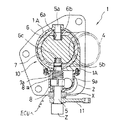
図1は本発明に係るサーモスタット装置の第一の実施の形態を示し、内燃機関等の循環流路に配置されるサーモスタット装置の破断平面図であり、図2の(a)は図1の側面図、同図の(b)は(a)のカム部材の作用の説明図である。
【0017】
図に示す本発明に係るサーモスタット装置1は、センサケース2内に循環流体の加熱または冷却を感知して膨張・収縮する熱膨張体のワックス3を内蔵しているが、このワックス3の膨張・収縮による体積変化に伴って摺動部材を構成するピストンロッド9を摺動させて、弁体6の回動開閉を行う。
そして、このワックス3を内蔵するセンサケース2は、ワックス3を内蔵した部分は、
前記循環流体の循環流路4内に配置されるとともに、前記摺動部材のピストンロッド9等は、循環流体に接しない循環流路4外に配置する構成としている。
【0018】
弁体6は、弁軸(支承軸)5aに支承されつつ、弁軸(トルク軸)5の回動により前記循環流路4を開閉を可能として配置されていて、循環流体の流量制御を行う機能を有するバタフライバルブ10とするものである。
また、このバタフライバルブ10の弁座であるシール部材7は、図9に示すように、弁体6が弁軸5、5aを回動軸として回動した際に、回動する弁体6の周縁部の回動軌跡に沿った形状に形成され、循環流路4の内壁4aの適宜位置に固着されている。
【0019】
前記ピストンロッド9の頭部は、バタフライバルブ10の一方の弁軸(トルク軸)5に装着されるカム部材8に、リテーナ9aを介して当接し、ピストンロッド9の摺動に伴って、この弁軸(トルク軸)5を回動させる。
なお、この弁軸(トルク軸)5には、手動によりその回動を可能とする回動補助手段の手動レバー11と、バタフライバルブ10の開閉角度の検出を行う角度検出手段の角度センサXが装着されていてる。
【0020】
ワックス3を内蔵するセンサケース2には、このワックス3を外部熱源により膨張・収縮させるための外部補助熱源手段である、電極20aとシールド線20bによる加熱素子20や、外部循環流体による外部配管30を備えている。
【0021】
なお、本実施の形態で説明する弁体6はバタフライバルブ10としたが、例えば、図10に示すロータリーバルブ、さらにはボールバルブ等の、弁体6を弁軸5により回動し、循環流体の流量制御を行うバルブであれば何れのものでもよく、その選択については、この弁体6が配置される循環流路4や流量等の諸条件によって決定すれば良い。
【0022】
ここでこのバタフライバルブ10についての説明を行う。
図1乃至図2に示す本実施の形態のバタフライバルブ10は、水冷式の内燃機関の循環冷却用として供されて、冷却液の循環流路4内に配置され、バタフライバルブ10の弁体6は、ピストンロッド9を備えるセンサケース2をトルク駆動源とするものである。
このバタフライバルブ10は、図に示すように、環状形状の弁体6の直径方向に突出する、一方の弁軸5であるトルク軸を弁本体1Aに回動可能に支承し、この環状形状の弁体6の回動開閉により、循環流路4を流通する冷却液の流量制御を行う流量制御弁である。
前記弁本体1Aには、弁体6の中心から弁本体1Aに向けて突出させた、弁体6を回動するための弁軸5を支承する軸受部が形成され、さらに前記弁体6には、弁本体1Aからこの弁体6の中心に向けて突出させ、この弁体6を支承するための弁軸5aの支承軸を支承する軸受部が形成されている。
【0023】
バタフライバルブ10の弁体6は、循環流路4を遮断する形状の環状形状とするものであって、前記弁軸(トルク軸)5を挿入係着し固定する一方、この弁体6には、弁体6を回動させるための穿設孔6aが形成され、前記弁軸(支承軸)5aを挿入支承することによって弁体6を回動自在としている。
そして、この穿設孔6aには、前述の弁本体1Aに突設された弁軸(支承軸)5aを回動軸として、弁体6を回動自在とするための軸受部材であるベアリング6bが埋設固着されている。
前記弁軸(支承軸)5aは、油圧による圧入加工、若しくは切削等の機械加工によって弁本体1Aに突設状態として加工されているために、循環流路4を流通する流体の圧力が上昇したとしても当該箇所からの流体の漏れを生ずることはない。なお、本実施の形態においては軸受部材としてベアリング6bを用いたが、転がりの性能が優れたブッシュ等の軸受部材としてもよい。
このような弁体6とすることにより、従来の弁体と比較して小型化ができ、同一の流量とするバタフライバルブ10と比較しても小型化を図ることができる。
【0024】
つぎに、このように構成されるバタフライバルブ10の駆動源であるセンサケース2と、このセンサケース2によりバタフライバルブ10が駆動する状態を説明する。
図1乃至図2に示すセンサケース2は、感温部であるワックス3を内蔵していて、このワックス3の膨張収縮がセンサケース2に内蔵されるダイヤフラム3aを押し上げて、このダイヤフラム3aの押し上げによってピストンロッド9の摺動を行う機構とするものである。
【0025】
そしてこのピストンロッド9の頭部には、図2の(b)に示すように、偏荷重防止と荷重面積の拡大のためのリテーナ9aが冠着されていて、弁軸(トルク軸)5に軸装されるカム部材8に当接するよう配置されている。
この弁軸(トルク軸)5の一方の先端部は、弁体6に形成される穿設孔6cに挿入係着され固定されているために、前記ピストンロッド9が摺動すると、このピストンロッド9の頭部が前記カム部材8を回動させ、この回動により弁体6を回動させる。また、弁軸(トルク軸)5の他方の先端部には回動補助手段の手動レバー11が装着されていて、この弁軸(トルク軸)5を手動により回動可能としている。
【0026】
さらにこの弁軸(トルク軸)5には、弁体6の開閉角度の検出を行うための角度検出手段である角度センサXと、弁体6の開閉角度の補填を行うための開閉補填手段であるアクチュエータZが配置されている。
前記角度検出手段である角度センサXは、弁体6の開閉角度の検出を行うとともに、この検出値を後述の電子制御装置ECUに送信する。
また、前記開閉補填手段のアクチュエータZは、ソレノイドやモータが用いられる。通常、トルクを要する開弁時等においてはワックス3の膨張によって弁体6の開弁を行っているが、弁体6の開弁の中間域から全開に至るまでは、ワックス3の膨張と伴にアクチュエータZを駆動させ、若しくはアクチュエータZのみの駆動により円滑な冷却液の流通が図られる。
なお、弁体6の開弁の中間域においては、電子制御装置ECUからの出力信号によって自由に開閉を行うことができる。
【0027】
なお、この弁軸(トルク軸)5には、その一端部を弁本体1Aに固定して、他端部をカム部材8に形成されるスプリング係止溝8bに係止するスプリング8aが、巻装されているが、このスプリング8aは、センサケース2のピストンロッド9の伸長によって開方向に回動される弁体6を、閉方向への回動を付勢するために巻装される。
【0028】
前記弁本体1Aの内側で回動する弁体6と弁本体1Aの間には、図9に示すように弁座であるシール部材7が弁本体1Aの内壁4aの適宜位置に固着されているが、このシール部材7は、弁体6と弁本体1Aによって生ずる隙間の補填、即ち弁体6を閉状態とした時に冷却液を確実に遮断する機能を有するものである。また、このシール部材7の弁軸(トルク軸)5との当接面には、この弁軸(トルク軸)5の円周面に凹状に形成される水切り溝5bに係合して凸状のシール部7aが形成されていて、バタフライバルブ10の水密性の保持が図られている。
【0029】
このシール部材7は、その材質を耐熱性・耐磨耗性等に優れたゴム、樹脂等の材質とするものであって、弁体6が弁軸5、5aを支承軸として回動した際に、回動する弁体6の周縁の回動軌跡に沿った形状に成形されている。
そして、循環流路4とは別部材で構成され回動軌跡に沿った形状に成形されることにより、固着位置の調整、若しくはシール部材7の形状をストレートなものに置き換えることによっては、同一の弁体6の開閉角度で、冷却液の流量特性を変化させることが可能となる。
【0030】
このような構成によるサーモスタット装置1の作用について説明する。
サーモスタット装置1に連結される循環流路4に配置されるセンサケース2内のワックス3が、冷却液の温度上昇により膨張する。このワックス3が膨張すると、ダイヤフラム3aを押し上げて、この押し上げに連動して図1乃至2に示すピストンロッド9を伸長させる。
このピストンロッド9の頭部は、リテーナ9aが冠着されるとともに、弁軸(トルク軸)5に軸装されるカム部材8に当接状態とするために、ピストンロッド9が伸長すると、弁軸(トルク軸)5を回動させ、図3に示す(a)の下降状態から、(b)の上昇状態とする。上昇状態とすることにより、弁体6は閉から開状態となり、循環流路4内で、冷却液を図3の(b)に示す矢印の方向へ流通させる。
なお、前記弁軸(トルク軸)5に軸装されるカム部材8の形状は、循環流路4を流通する冷却液の流量に適合するようその外形は成形されているが、この外形を変化させることにより、冷却液の流量を変化させることも可能である。
【0031】
循環流路4を流通する冷却液の温度上昇によって、弁体6は弁軸(トルク軸)5の回動により開閉を行う一方、弁軸(トルク軸)5に備えられる角度センサXは、弁体6の開閉角度、即ち弁軸(トルク軸)5の回動角度を検出し、この検出データを接続される電子制御装置ECUに送信する。
電子制御装置ECUにおいては、図4に示すように弁体6の開閉角度の他、公知の手段によって検出された、循環流路4の温度センサYによる冷却液の温度や、内燃機関Eの回転数や、外気温センサTによる外気温度等の内燃機関Eの様々なデータを、内部のメモリ等の記憶部に予め記憶された記憶内容と比較を行って、診断部において内燃機関Eの複数箇所の診断を行う。
【0032】
例えば、サーモスタット装置1の弁体作動開始温度が摂氏80度で全開時温度を95度とする装置を備える内燃機関Eにおいて、温度センサYが冷却液の温度を90度、角度センサXが弁体の開閉角度を全開というデータを電子制御装置ECUに送信した場合には、電子制御装置ECUに予め記憶されたこのサーモスタット装置1のデータ(弁体作動開始温度が摂氏80度で全開時温度が95度)と比較を行い、比較の結果、サーモスタット装置1が故障していると判断した場合には表示ランプやブザや音声出力装置等の報知手段Lに出力を行うものである。なお、上述の例示は一例であって、様々な状況を想定して電子制御装置ECUの記憶部や診断部に多量の情報(例えば、故障データである被害情報や規格情報)を格納・保存して、想定される状況を容易に把握し、的確な対応を可能とすることができるのは勿論である。
また、前記の報知手段Lは、運転者に確実に故障を明示する箇所である、ダッシュボードの各種計器類の近傍に設けるとよい。
【0033】
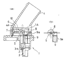
図5は以上説明のサーモスタット装置1に、外部熱源である、PTC、ペルチェ素子等の加熱素子20を、センサケース2に近接して組み込んだサーモスタット装置1の破断側面図を示すものであるが、このサーモスタット装置1によれば、内燃機関等の暖気運転が不十分なために循環流路4を流通する冷却液の温度が上昇せず、且つ、サーモスタット装置1の弁体6を開方向に作動を必要とする場合等に、有効な機能として活用ができるものであるとともに、加熱素子20の電極20aとシールド線20bが循環流路4の外部の冷却液に接しない位置に配置されるために、冷却液の浸入等によるショート等の事故の防止ができる。
【0034】
また、図6乃至図7は、このサーモスタット装置1に、ウインドウォッシャ液等の外部配管30をセンサケース2内に組み込んだサーモスタット装置1の平面図と破断側面図であるが、このサーモスタット装置1によれば、この外部配管30をウインドウォッシャ液等の貯留タンク(図示せず)に連結して循環させることにより、ワックス3を冷却して意識的にバルブを閉じることができるとともに、冷却液によりウインドウォッシャ液が温められて、冬季においてはフロントガラスに付着する雪や氷を容易に除去する機能を付加することができる。
【0035】
さらに図8は図6乃至図7に示す外部配管30をセンサケース2内に組み込んだサーモスタット装置1の、他の実施の形態例であるが、この図に示すように、外部配管30は極めて自由な配管とすることができる。
また、図5乃至図8に示すように、サーモスタット装置1に加熱素子20と外部配管30とを組み合わせることにより、前述の如く循環流路4の冷却液だけによらずにサーモスタット装置1を加熱または冷却することが可能であり、さらに多機能なサーモスタット装置1とするこができる。
なお、前記加熱素子20のペルチェ素子は、極性を反転させて接続させることにより加熱・冷却の双方の作用を有するために、この加熱素子20を用いることによってサーモスタット装置1の設計の自由度が増大する。
【0036】
【発明の効果】
以上説明を行った本発明のサーモスタット装置によれば次のような効果を奏する。
【0037】
(1)センサケースの熱膨張体を内蔵した部分は、循環流体の循環流路内に配置するとともに、摺動部材は、循環流体に接しない循環流路外に配置する構成としたことによって、ピストンロッド等の摺動部材が直接冷却液中に接触することがなくなり、冷却液の浸入や冷却液に含まれる成分による、摺動部材の浸食等の事故の防止を図ることが可能となる。
(2)また、循環流路内における通水抵抗の大きいポペットバルブに代えて、弁軸を有し、この弁軸を回動させて流量制御を行うバルブとしたことにより、同一流量を得るために必要とされるポペットバルブよりも小型化が可能となり、従って、循環流路の冷却液を圧送するウォーターポンプの負担の低減化やラジエータの小型化ができるとともに、装置自体の小型化をも図ることが可能となる。
(3)さらに、ポペットバルブに代えて、弁軸を有し、この弁軸を回動させて流量制御を行うバルブとしたことにより、循環流路の冷却液が開弁する弁体から直接センサケースに当接させることができるために、センサケースの感温性が向上し、従って、サーモスタット装置の応答性能の向上を図ることが可能となる。
(4)循環流路に充填する冷却液によるセンサケースの加熱冷却に加え、PTC素子やペルチェ素子等の加熱素子によりセンサケースの加熱を行う場合には、これらの加熱素子への配線を、循環流路内の冷却液を経由することなくできるために、漏水によるショート等の事故を防止することが可能となる。
(5)また、センサケースの加熱冷却を冷却液や加熱素子によるものに加え、ウインドウォッシャー液用の配管をセンサケースに付加すことによって、ワックスを冷却して意識的にバルブを閉じることができるとともに、冬季におけるフロントガラスに付着した氷や雪の除去が可能となる。さらに、車両の空調用のエアコン配管のセンサケースへの付加や、加熱素子のペルチェ素子の極性を反転させての接続によっても、センサケース自体の冷却が可能となる。
(6)そして、弁軸に弁体の開閉角を検出する角度センサを取付け、さらに公知の循環流路に配置される温度センサや、内燃機関の回転数や、外気温センサ等からの配信データを、ECUにて比較・診断を行い、さらに報知手段により出力することにより、運転者に確実に作動状況を把握させるとともに、内燃機関のフェイルセイフ機能を考慮した運転が可能となる。
(7)弁軸に手動レバーを取り付けたことによって、サーモスタット装置の外部からの操作が可能となり、万一の故障の場合におけるサーモスタット装置の開閉が可能となるとともに、循環流路に冷却液を新規に充填、若しくは交換を行う際にも、この手動レバーの開閉操作によって注入性の向上を図ることが可能となる。
【図面の簡単な説明】
【図1】本発明に係るサーモスタット装置の第一の実施の形態を示し、内燃機関等の循環流路に配置されるサーモスタット装置の破断平面図である。
【図2】(a)は図1の側面図であり、(b)は(a)のカム部材の作用の説明図である。
【図3】ピストンロッドとカム部材との関係の動作説明図であり、(a)は、ピストンロッドが下降時の状態を示し、(b)はピストンロッドが上昇時の状態を示す説明図である。
【図4】本発明のサーモスタット装置を配置する循環流路の該略図である。
【図5】外部熱源である加熱素子をセンサケースに付加した状態を説明する破断側面図である。
【図6】ウインドウォッシャー液等の配管をセンサケースに付加した状態を説明する平面図である。
【図7】図5の一部破断側面図である。
【図8】図6の他の実施の形態を示す側面図である。
【図9】シール部材(弁座)の配置を説明する側面断面図である。
【図10】弁軸を有する他の弁体による、他の実施の形態例の断面側面図であり、(a)は弁体が閉状態を、(b)は開状態を示すものである。
【図11】従来のサーモスタット装置を配置する循環流路の破断側面図である。
【図12】従来の第二のサーモスタット装置であって、センサケース内に加熱素子を備えたるサーモスタット装置を配置する循環流路の破断側面図である。
【符号の説明】
1 サーモスタット装置
1A 弁本体
2 センサケース
3 ワックス
3a ダイヤフラム
4 循環流路
4a 内壁(循環流路)
5 弁軸(トルク軸)
5a 弁軸(支承軸)
6 弁体
6a 穿設穴
6b ベアリング
7 シール部材(弁座)
7a シール部
8 カム部材
8a スプリング
8b スプリング係止溝
9 ピストンロッド
9a リテーナ
10 バタフライバルブ
11 手動レバー
20 加熱素子
20a 電極
20b シールド線
30 外部配管
50 サーモスタット装置(第一の従来例)
50A サーモスタット装置(第二の従来例)
51 センサケース
51A センサケース(第二の従来例)
52 ピストンガイド
52A ピストンガイド(第二の従来例)
53 ピストンロッド
53 ピストンロッド(第二の従来例)
54 弁体
54 弁体(第二の従来例)
55 コイルスプリング
55A コイルスプリング(第二の従来例)
56 フランジ部
57 嵌合穴
58 開閉部
E 内燃機関
L 報知手段
T 外気温センサ
X 角度センサ
Y 温度センサ
Z アクチュエータ[0001]
BACKGROUND OF THE INVENTION
The present invention incorporates a thermal expansion body that is disposed in a circulation flow path and expands and contracts by sensing heating or cooling of the circulating fluid, and a sliding member according to a volume change due to expansion and contraction of the thermal expansion body And a thermostat device for opening and closing a valve body having a valve shaft.
[0002]
[Prior art]
In general, a thermostat device disposed in a cooling system such as an internal combustion engine includes a sensor case that incorporates a thermal expansion body that expands and contracts by sensing a temperature change of a coolant filled in a circulation flow path of the cooling system, The valve body is opened and closed by a volume change accompanying expansion and contraction of the thermal expansion body, and the coolant is held at a predetermined temperature.
[0003]
FIG. 11 is a cutaway side view of the circulation flow path 4 in which the
In the circulation channel 4, the
[0004]
In the
As described above, since the tip of the
[0005]
FIG. 12 is a cutaway side view of the circulation flow path 4 in which another
[0006]
[Problems to be solved by the invention]
The above-described conventional poppet
Furthermore, the coolant of the circulation channel cannot be directly brought into contact with the sensor case due to the obstruction of the poppet
When such a situation occurs, it is not possible to expect a good circulation of the coolant through the circulation flow path 4, and at the same time, the operation of the internal combustion engine or the like may be seriously affected.
[0007]
Further, in order to obtain the
Further, when the air is vented when the coolant is filled in the circulation flow path 4, the operation is performed by operating a jiggle valve (not shown) of the thermostat. In the unlikely event that a failure occurs in the
[0008]
Furthermore, in the
[0009]
Therefore, in view of these problems, the thermostat device of the present invention is intended to enable good sliding without impairing the sliding function by intrusion of the coolant, and by reducing the size of the circulation flow path. It is an object of the present invention to provide a thermostat device that can improve the degree of freedom of design and that can be manually opened and closed by a valve.
[0010]
[Means for Solving the Problems]
In order to solve the above-described problems, the thermostat device of the present invention incorporates a thermal expansion body that expands and contracts by sensing the heating or cooling of the circulating fluid in the circulation flow path. In the thermostat device that opens and closes the valve body by sliding the sliding member with the volume change due to expansion and contraction,Sensor caseBuilt-in thermal expansion bodyPartIs disposed in the circulation flow path of the circulating fluid, and the sliding member is disposed in the circulating fluid.Do not touchPlace outside the circulation channelIt is characterized by that.
[0011]
Desirably, the valve body has a function of opening and closing the circulation flow path by rotation of a valve shaft and performing a flow rate control of the circulating fluid. It is formed in a shape that engages with rotation and is fixed to the inner wall of the circulation flow path.
[0012]
The sliding member includes a slidable piston rod, the head of the piston rod is brought into contact with a cam member mounted on the valve shaft of the valve body, and the piston rod slides. Accordingly, the valve shaft is configured to rotate.
[0013]
The valve shaft is provided with a rotation assisting means that enables the valve shaft to be manually rotated, and the valve shaft further includes an angle detection means for detecting an opening / closing angle of the valve body. It is set as the structure provided.
[0014]
Furthermore, the sensor case containing the thermal expansion body includes an external auxiliary heat source means for expanding and contracting the thermal expansion body by an external heat source.
[0015]
DETAILED DESCRIPTION OF THE INVENTION
An embodiment of a thermostat device according to the present invention having such a configuration will be described with reference to the accompanying drawings.
[0016]
FIG. 1 shows a first embodiment of a thermostat device according to the present invention, and is a cut-away plan view of a thermostat device arranged in a circulation flow path of an internal combustion engine or the like. FIG. 2 (a) is a side view of FIG. (B) of the figure is an explanatory view of the operation of the cam member of (a).
[0017]
The
The
The
[0018]
The
Further, as shown in FIG. 9, the
[0019]
The head of the
The valve shaft (torque shaft) 5 includes a
[0020]
The
[0021]
Although the
[0022]
Here, the
A
As shown in the figure, the
The
[0023]
The
The
Since the valve shaft (support shaft) 5a is processed in a projecting state on the
By setting it as such a
[0024]
Next, the
The
[0025]
As shown in FIG. 2 (b), a
Since one end portion of the valve shaft (torque shaft) 5 is inserted and fixed in a
[0026]
Further, the valve shaft (torque shaft) 5 includes an angle sensor X which is an angle detection means for detecting the opening / closing angle of the
The angle sensor X, which is the angle detection means, detects the opening / closing angle of the
The actuator Z of the opening / closing compensation means is a solenoid or a motor. Normally, the
In the middle region of the
[0027]
The valve shaft (torque shaft) 5 is provided with a spring 8a having one end fixed to the
[0028]
Between the
[0029]
The
And it is the same by adjusting the adhering position or replacing the shape of the
[0030]
The operation of the
Sensor case arranged in the circulation channel 4 connected to the thermostat device 12The inner wax 3 expands due to the temperature rise of the coolant. When the wax 3 expands, the
The head of the
The shape of the
[0031]
The
In the electronic control unit ECU, as shown in FIG. 4, in addition to the opening / closing angle of the
[0032]
For example, in an internal combustion engine E having a device in which the valve body operation start temperature of the
Further, the notification means L is preferably provided in the vicinity of various instruments on the dashboard, which is a location that clearly indicates the failure to the driver.
[0033]
FIG. 5 shows the
[0034]
6 to 7 are a plan view and a cutaway side view of the
[0035]
8 shows another embodiment of the
Further, as shown in FIG. 5 to FIG. 8, by combining the
Since the Peltier element of the
[0036]
【The invention's effect】
The thermostat device according to the present invention described above has the following effects.
[0037]
(1)Sensor caseBuilt-in thermal expansion bodyPartAre arranged in the circulation flow path of the circulating fluid and the sliding member is the circulating fluidDo not touchThe arrangement outside the circulation channel prevents the sliding member such as the piston rod from coming into direct contact with the cooling liquid, so that the sliding member is eroded by the ingress of cooling liquid and components contained in the cooling liquid. It is possible to prevent such accidents.
(2) In addition, in order to obtain the same flow rate by using a valve shaft that controls the flow rate by rotating the valve shaft instead of the poppet valve having a high water flow resistance in the circulation flow path. This makes it possible to reduce the size of the poppet valve required for the pump, and therefore, it is possible to reduce the burden on the water pump that pumps the coolant in the circulation flow path, the size of the radiator, and the size of the device itself. It becomes possible.
(3) Further, in place of the poppet valve, a valve shaft is provided, and the valve shaft is rotated to control the flow rate. Since the sensor case can be brought into contact with the case, the temperature sensitivity of the sensor case is improved, and therefore the response performance of the thermostat device can be improved.
(4) When the sensor case is heated by a heating element such as a PTC element or a Peltier element in addition to the heating / cooling of the sensor case by the coolant filling the circulation channel, the wiring to these heating elements is circulated. In the flow pathCooling liquidTherefore, it is possible to prevent accidents such as a short circuit due to water leakage.
(5) Also, by adding heating and cooling of the sensor case to the cooling liquid or heating element and adding a pipe for window washer liquid to the sensor case, the wax can be cooled and the valve can be closed consciously. At the same time, it is possible to remove ice and snow attached to the windshield in winter. Furthermore, the sensor case itself can be cooled by adding an air conditioning pipe for air conditioning of the vehicle to the sensor case or by connecting the heating element with the polarity of the Peltier element reversed.
(6) Then, an angle sensor for detecting the opening / closing angle of the valve element is attached to the valve shaft, and distribution data from a temperature sensor arranged in a known circulation flow path, the rotational speed of the internal combustion engine, an outside air temperature sensor, etc. Are compared and diagnosed by the ECU, and further output by the notifying means, so that the driver can be surely grasped the operating condition and can be operated in consideration of the fail-safe function of the internal combustion engine.
(7) By attaching a manual lever to the valve shaft, it is possible to operate the thermostat device from the outside. In the event of a failure, the thermostat device can be opened and closed, and a new coolant is added to the circulation channel. Even when filling or exchanging, the openability of the manual lever can improve the injection performance.
[Brief description of the drawings]
FIG. 1 shows a first embodiment of a thermostat device according to the present invention, and is a cutaway plan view of a thermostat device disposed in a circulation flow path of an internal combustion engine or the like.
2A is a side view of FIG. 1, and FIG. 2B is an explanatory view of the operation of the cam member of FIG.
FIGS. 3A and 3B are operation explanatory views of the relationship between the piston rod and the cam member, in which FIG. 3A shows a state when the piston rod is lowered, and FIG. 3B is an explanatory view showing a state when the piston rod is raised; is there.
FIG. 4 is a schematic view of a circulation channel in which a thermostat device of the present invention is disposed.
FIG. 5 is a cutaway side view illustrating a state where a heating element as an external heat source is added to a sensor case.
FIG. 6 is a plan view for explaining a state in which piping such as window washer liquid is added to the sensor case.
7 is a partially cutaway side view of FIG. 5. FIG.
FIG. 8 is a side view showing another embodiment of FIG. 6;
FIG. 9 is a side sectional view for explaining the arrangement of a seal member (valve seat).
FIGS. 10A and 10B are cross-sectional side views of another embodiment using another valve body having a valve shaft, wherein FIG. 10A shows a closed state and FIG. 10B shows an open state.
FIG. 11 is a cutaway side view of a circulation channel in which a conventional thermostat device is arranged.
FIG. 12 is a cutaway side view of a circulation flow path in which a thermostat device having a heating element is disposed in a sensor case, which is a conventional second thermostat device.
[Explanation of symbols]
1 Thermostat device
1A Valve body
2 Sensor case
3 Wax
3a Diaphragm
4 Circulation channel
4a Inner wall (circulation flow path)
5 Valve shaft (torque shaft)
5a Valve shaft (support shaft)
6 Disc
6a Drilling hole
6b Bearing
7 Seal member (valve seat)
7a Seal part
8 Cam member
8a Spring
8b Spring locking groove
9 Piston rod
9a Retainer
10 Butterfly valve
11 Manual lever
20 Heating element
20a electrode
20b Shielded wire
30 External piping
50 Thermostat device (first conventional example)
50A thermostat device (second conventional example)
51 Sensor case
51A Sensor Case (Second Conventional Example)
52 Piston guide
52A Piston Guide (Second Conventional Example)
53 Piston rod
53 Piston rod (second conventional example)
54 Disc
54 Valve body (second conventional example)
55 Coil spring
55A coil spring (second conventional example)
56 Flange
57 Mating hole
58 Opening and closing part
E Internal combustion engine
L Notification means
T outside air temperature sensor
X angle sensor
Y temperature sensor
Z Actuator
Claims (7)
センサケースの前記熱膨張体を内蔵した部分は、前記循環流体の循環流路内に配置するとともに、前記摺動部材は、前記循環流体に接しない循環流路外に配置することを特徴とする、サーモスタット装置。A thermal expansion body that expands and contracts by sensing the heating or cooling of the circulating fluid in the circulation flow path is built in, and the sliding member is slid along with the volume change caused by the expansion and contraction of the thermal expansion body. In the thermostat device that opens and closes the body,
Portion which incorporates the thermal expansion of the sensor case, while disposed in the circulation flow path of the circulating fluid, said sliding member, characterized in that arranged outside the circulation channel which is not in contact with the circulating fluid , Thermostat device.
弁軸の回動により前記循環流路を開閉可能とし、前記循環流体の流量制御を行うことを特徴とする、
請求項1に記載のサーモスタット装置。The valve body is
The circulation channel can be opened and closed by rotating a valve shaft, and the flow rate of the circulating fluid is controlled.
The thermostat device according to claim 1.
当該弁体の回動に係合する形状に形成し、前記循環流路の内壁に固着されることを特徴とする、
請求項2に記載のサーモスタット装置。The valve seat of the valve body is
It is formed in a shape that engages with the rotation of the valve body, and is fixed to the inner wall of the circulation channel,
The thermostat device according to claim 2.
摺動可能とするピストンロッドを備え、当該ピストンロッドの頭部を、前記弁体の前記弁軸に装着されるカム部材に当接させ、当該ピストンロッドの摺動に伴って、当該弁軸を回動させることを特徴とする、
請求項2又は請求項3に記載のサーモスタット装置。The sliding member is
A piston rod that is slidable, the head of the piston rod is brought into contact with a cam member mounted on the valve shaft of the valve body, and the valve shaft is moved along with the sliding of the piston rod. It is characterized by rotating,
The thermostat device according to claim 2 or claim 3.
当該弁軸が、手動によりその回動を可能とする回動補助手段を備えることを特徴とする、
請求項2乃至請求項4の何れか1項に記載のサーモスタット装置。In the valve stem,
The valve shaft is provided with a rotation assisting means that enables the valve to be manually rotated.
The thermostat device according to any one of claims 2 to 4.
前記弁体の開閉角度の検出を行う角度検出手段を備えることを特徴とする、
請求項2乃至請求項5の何れか1項に記載のサーモスタット装置。In the valve stem,
Characterized in that it comprises angle detection means for detecting the opening and closing angle of the valve body,
The thermostat device according to any one of claims 2 to 5.
当該熱膨張体を外部熱源により膨張・収縮させるための外部補助熱源手段を備えることを特徴とする、
請求項1乃至請求項6の何れか1項に記載のサーモスタット装置。In the sensor case containing the thermal expansion body,
It comprises an external auxiliary heat source means for expanding and contracting the thermal expansion body by an external heat source,
The thermostat device according to any one of claims 1 to 6.
Priority Applications (6)
| Application Number | Priority Date | Filing Date | Title |
|---|---|---|---|
| JP18421997A JP3739898B2 (en) | 1997-07-09 | 1997-07-09 | Thermostat device |
| EP97306884A EP0890717A3 (en) | 1997-07-09 | 1997-09-04 | Thermostat device |
| TW086112784A TW426782B (en) | 1997-07-09 | 1997-09-04 | Thermostat device |
| KR1019970045988A KR19990013220A (en) | 1997-07-09 | 1997-09-05 | Thermostat |
| US08/935,912 US6189798B1 (en) | 1997-07-09 | 1997-09-23 | Thermostat device |
| CA002217386A CA2217386A1 (en) | 1997-07-09 | 1997-10-01 | Thermostat device |
Applications Claiming Priority (1)
| Application Number | Priority Date | Filing Date | Title |
|---|---|---|---|
| JP18421997A JP3739898B2 (en) | 1997-07-09 | 1997-07-09 | Thermostat device |
Publications (2)
| Publication Number | Publication Date |
|---|---|
| JPH1130358A JPH1130358A (en) | 1999-02-02 |
| JP3739898B2 true JP3739898B2 (en) | 2006-01-25 |
Family
ID=16149459
Family Applications (1)
| Application Number | Title | Priority Date | Filing Date |
|---|---|---|---|
| JP18421997A Expired - Fee Related JP3739898B2 (en) | 1997-07-09 | 1997-07-09 | Thermostat device |
Country Status (6)
| Country | Link |
|---|---|
| US (1) | US6189798B1 (en) |
| EP (1) | EP0890717A3 (en) |
| JP (1) | JP3739898B2 (en) |
| KR (1) | KR19990013220A (en) |
| CA (1) | CA2217386A1 (en) |
| TW (1) | TW426782B (en) |
Cited By (1)
| Publication number | Priority date | Publication date | Assignee | Title |
|---|---|---|---|---|
| KR101567434B1 (en) | 2014-07-31 | 2015-11-12 | 인지컨트롤스 주식회사 | Fail safety coolant control valve |
Families Citing this family (23)
| Publication number | Priority date | Publication date | Assignee | Title |
|---|---|---|---|---|
| US6279390B1 (en) * | 1996-12-17 | 2001-08-28 | Denso Corporation | Thermostat malfunction detecting system for engine cooling system |
| DE19906057A1 (en) * | 1999-02-12 | 2000-08-17 | Behr Thermot Tronik Gmbh & Co | Thermostatic valve has arrangement for detecting open and/or closed position connected to evaluation device for generating different signals when valve sticks in open or closed position |
| EP1103703B1 (en) * | 1999-03-23 | 2010-04-07 | Nippon Thermostat Co., Ltd. | Thermostat device |
| DE10056076A1 (en) * | 2000-11-07 | 2002-06-13 | Behr Thermot Tronik Gmbh | valve housing |
| KR100715433B1 (en) * | 2001-04-04 | 2007-05-09 | 한라공조주식회사 | Tube for heat exchanger |
| KR100743511B1 (en) * | 2001-04-09 | 2007-07-27 | 한라공조주식회사 | Aluminum radiator |
| ATE241051T1 (en) | 2001-04-14 | 2003-06-15 | Kaldewei Franz Gmbh & Co | DEVICE FOR CONTROLLING THE TUB FILLING OF A SANITARY TUB |
| DE10155386A1 (en) * | 2001-11-10 | 2003-05-22 | Bosch Gmbh Robert | Valve with an emergency function |
| US20030233320A1 (en) * | 2002-06-13 | 2003-12-18 | Connor Robert W. | Unified electronic transaction fulfillment |
| US7784705B2 (en) | 2006-02-27 | 2010-08-31 | Honeywell International Inc. | Controller with dynamic temperature compensation |
| JP2007333068A (en) | 2006-06-14 | 2007-12-27 | Toyota Motor Corp | Thermovalve |
| US8280673B2 (en) | 2007-12-04 | 2012-10-02 | Honeywell International Inc. | System for determining ambient temperature |
| US9335769B2 (en) | 2007-12-04 | 2016-05-10 | Honeywell International Inc. | System for determining ambient temperature |
| US8429009B2 (en) * | 2008-07-16 | 2013-04-23 | Paycode Inc. | Universal affinity system |
| JP5164281B2 (en) * | 2010-04-27 | 2013-03-21 | 日本サーモスタット株式会社 | Fluid control valve device |
| JP5925456B2 (en) | 2011-09-22 | 2016-05-25 | 株式会社ミクニ | Cooling water control valve device |
| JP5957949B2 (en) * | 2012-02-24 | 2016-07-27 | スズキ株式会社 | Combustion state control device |
| US9416988B2 (en) | 2013-03-15 | 2016-08-16 | Honeywell International Inc. | Self-aligning back plate for an electronic device |
| RU2514553C1 (en) * | 2013-04-26 | 2014-04-27 | Александр Алексеевич Семенов | Thermostat with electromagnetic control |
| WO2015030724A1 (en) * | 2013-08-27 | 2015-03-05 | Melling Do Brasil Componentes Automotivos Ltda. | Temperature control apparatus and method for an automotive cooling system |
| EP3006794B1 (en) * | 2014-07-31 | 2017-12-13 | Inzi Controls Co., Ltd. | Fail safety control valve of cooling water |
| CN104989513A (en) * | 2015-06-25 | 2015-10-21 | 苏细调 | Controller for engine device |
| US10024219B2 (en) * | 2015-11-19 | 2018-07-17 | Hyundai Motor Company | Engine system having coolant control valve |
Family Cites Families (10)
| Publication number | Priority date | Publication date | Assignee | Title |
|---|---|---|---|---|
| FR632566A (en) * | 1928-01-11 | |||
| US1528788A (en) * | 1919-02-06 | 1925-03-10 | Beneke Mfg Company | Thermostatic valve |
| US2454141A (en) * | 1939-05-02 | 1948-11-16 | Dole Valve Co | Thermostatic liquid controlling device |
| US3014467A (en) * | 1960-07-22 | 1961-12-26 | Int Harvester Co | Engine temperature regulating means |
| GB1099933A (en) * | 1964-06-22 | 1968-01-17 | Walton Eng Co Ltd | Improvements in or relating to thermostatically controlled valves |
| US3384056A (en) * | 1966-08-01 | 1968-05-21 | Waukesha Motor Co | Temperature control systems for internal combustion engines |
| GB1200244A (en) * | 1968-01-18 | 1970-07-29 | Walton Engineering Company Ltd | Improvements in or relating to temperature responsive flow control arrangements |
| US4294226A (en) * | 1980-01-21 | 1981-10-13 | Emanuel Feinberg | Automatic furnace vent damper control |
| DE3444417A1 (en) * | 1984-12-04 | 1986-06-12 | Mtu Motoren- Und Turbinen-Union Friedrichshafen Gmbh, 7990 Friedrichshafen | SWING VALVE |
| JPH08121613A (en) * | 1994-10-18 | 1996-05-17 | Hiroshi Kasahara | Butterfly valve |
-
1997
- 1997-07-09 JP JP18421997A patent/JP3739898B2/en not_active Expired - Fee Related
- 1997-09-04 EP EP97306884A patent/EP0890717A3/en not_active Withdrawn
- 1997-09-04 TW TW086112784A patent/TW426782B/en active
- 1997-09-05 KR KR1019970045988A patent/KR19990013220A/en not_active Application Discontinuation
- 1997-09-23 US US08/935,912 patent/US6189798B1/en not_active Expired - Lifetime
- 1997-10-01 CA CA002217386A patent/CA2217386A1/en not_active Abandoned
Cited By (2)
| Publication number | Priority date | Publication date | Assignee | Title |
|---|---|---|---|---|
| KR101567434B1 (en) | 2014-07-31 | 2015-11-12 | 인지컨트롤스 주식회사 | Fail safety coolant control valve |
| WO2016017853A1 (en) * | 2014-07-31 | 2016-02-04 | 인지컨트롤스주식회사 | Fail safety control valve of cooling water |
Also Published As
| Publication number | Publication date |
|---|---|
| EP0890717A3 (en) | 2000-07-26 |
| JPH1130358A (en) | 1999-02-02 |
| EP0890717A2 (en) | 1999-01-13 |
| TW426782B (en) | 2001-03-21 |
| US6189798B1 (en) | 2001-02-20 |
| CA2217386A1 (en) | 1999-01-09 |
| KR19990013220A (en) | 1999-02-25 |
Similar Documents
| Publication | Publication Date | Title |
|---|---|---|
| JP3739898B2 (en) | Thermostat device | |
| JP4400909B2 (en) | Thermostat device | |
| EP0978641B1 (en) | Cooling control system for an internal combustion engine | |
| US8118124B2 (en) | Fail-safe air flap control apparatus for vehicle | |
| JP6350255B2 (en) | Refrigerant control valve device | |
| GB2514273B (en) | Valve with integrated motor bypass fail safe | |
| US7987822B2 (en) | Electromechanical failsafe thermostat | |
| US6745995B2 (en) | Electromagnetically controlled butterfly thermostat valve | |
| US20170122181A1 (en) | Cooling control device, flow rate control valve and cooling control method | |
| JPH0531294Y2 (en) | ||
| CA2325168A1 (en) | Electronically controlled thermostat | |
| JPH11294163A (en) | Cooling control device for internal combustion engine | |
| CA2431717C (en) | Proportional valve with linear actuator | |
| JP2002257248A (en) | Flow control valve and cooling device for internal combustion engine using the same | |
| US5558192A (en) | Fluid coupling and external control therefor | |
| JP5034949B2 (en) | Thermostat device and associated method | |
| Kenny et al. | Electronic thermostat system for automotive engines | |
| JPH10220639A (en) | Self-diagnostic device for switching valve | |
| US5996755A (en) | Temperature sensitive decoupling method for viscous fan drives | |
| JP4098877B2 (en) | Thermo element | |
| JP3361739B2 (en) | Idle speed control valve | |
| JP5799530B2 (en) | Cooling device for internal combustion engine | |
| JP7335396B2 (en) | Flow control valve and cooling system | |
| CN1204792A (en) | Thermostat | |
| KR100587804B1 (en) | Thermostat |
Legal Events
| Date | Code | Title | Description |
|---|---|---|---|
| A621 | Written request for application examination |
Free format text: JAPANESE INTERMEDIATE CODE: A621 Effective date: 20040122 |
|
| A977 | Report on retrieval |
Free format text: JAPANESE INTERMEDIATE CODE: A971007 Effective date: 20050714 |
|
| A131 | Notification of reasons for refusal |
Free format text: JAPANESE INTERMEDIATE CODE: A131 Effective date: 20050727 |
|
| A521 | Request for written amendment filed |
Free format text: JAPANESE INTERMEDIATE CODE: A523 Effective date: 20050915 |
|
| TRDD | Decision of grant or rejection written | ||
| A01 | Written decision to grant a patent or to grant a registration (utility model) |
Free format text: JAPANESE INTERMEDIATE CODE: A01 Effective date: 20051026 |
|
| A61 | First payment of annual fees (during grant procedure) |
Free format text: JAPANESE INTERMEDIATE CODE: A61 Effective date: 20051104 |
|
| R150 | Certificate of patent or registration of utility model |
Free format text: JAPANESE INTERMEDIATE CODE: R150 |
|
| FPAY | Renewal fee payment (event date is renewal date of database) |
Free format text: PAYMENT UNTIL: 20081111 Year of fee payment: 3 |
|
| FPAY | Renewal fee payment (event date is renewal date of database) |
Free format text: PAYMENT UNTIL: 20091111 Year of fee payment: 4 |
|
| FPAY | Renewal fee payment (event date is renewal date of database) |
Free format text: PAYMENT UNTIL: 20091111 Year of fee payment: 4 |
|
| FPAY | Renewal fee payment (event date is renewal date of database) |
Free format text: PAYMENT UNTIL: 20091111 Year of fee payment: 4 |
|
| FPAY | Renewal fee payment (event date is renewal date of database) |
Free format text: PAYMENT UNTIL: 20101111 Year of fee payment: 5 |
|
| FPAY | Renewal fee payment (event date is renewal date of database) |
Free format text: PAYMENT UNTIL: 20101111 Year of fee payment: 5 |
|
| FPAY | Renewal fee payment (event date is renewal date of database) |
Free format text: PAYMENT UNTIL: 20111111 Year of fee payment: 6 |
|
| FPAY | Renewal fee payment (event date is renewal date of database) |
Free format text: PAYMENT UNTIL: 20111111 Year of fee payment: 6 |
|
| FPAY | Renewal fee payment (event date is renewal date of database) |
Free format text: PAYMENT UNTIL: 20121111 Year of fee payment: 7 |
|
| FPAY | Renewal fee payment (event date is renewal date of database) |
Free format text: PAYMENT UNTIL: 20121111 Year of fee payment: 7 |
|
| FPAY | Renewal fee payment (event date is renewal date of database) |
Free format text: PAYMENT UNTIL: 20121111 Year of fee payment: 7 |
|
| FPAY | Renewal fee payment (event date is renewal date of database) |
Free format text: PAYMENT UNTIL: 20131111 Year of fee payment: 8 |
|
| R250 | Receipt of annual fees |
Free format text: JAPANESE INTERMEDIATE CODE: R250 |
|
| LAPS | Cancellation because of no payment of annual fees |