JP3737273B2 - Button telephone apparatus and incoming call reception method thereof - Google Patents
Button telephone apparatus and incoming call reception method thereof Download PDFInfo
- Publication number
- JP3737273B2 JP3737273B2 JP06288998A JP6288998A JP3737273B2 JP 3737273 B2 JP3737273 B2 JP 3737273B2 JP 06288998 A JP06288998 A JP 06288998A JP 6288998 A JP6288998 A JP 6288998A JP 3737273 B2 JP3737273 B2 JP 3737273B2
- Authority
- JP
- Japan
- Prior art keywords
- telephone
- extension number
- call
- setting
- incoming call
- Prior art date
- Legal status (The legal status is an assumption and is not a legal conclusion. Google has not performed a legal analysis and makes no representation as to the accuracy of the status listed.)
- Expired - Fee Related
Links
Images


Description
【0001】
【発明の属する技術分野】
本発明は、通話中に第三者からの呼びがあった場合の当該呼びの制御に関する。
【0002】
【従来の技術】
従来の電話交換装置のうちボタン電話装置では、内線のボタン電話機に仮想内線番号を割当てることができる。ここで、仮想内線番号とは、物理的な収容位置及び電話機ユニットを持たない内線に割当てられた番号のことである。例えば、200番の内線番号が割り当てられたボタン電話機に、他の内線端末に割り当てられている500番、501番などの内線番号も仮想内線番号として割り当てることができる。このようなボタン電話機は通常本来の200番の内線番号を利用して通話できるが、500又は501番の仮想内線番号を利用しても通話することができる。
【0003】
次に、従来のボタン電話装置の内線番号呼び出し処理について説明する。内線に着信があると、まず、内線番号に基づき着信分析を行い、着信先を検索する。次にこの内線番号のボタン電話機が通話中かどうかを判定し、通話中でなければ、発信側に呼び出し音を送出して、処理を終了する。一方、通話中であれば、発信側に話中音を返送して、処理を終了する。
従って、ボタン電話機本来の内線番号、上記の例では200番を使用して通話しているときに、この200番に別のところから着信があっても、発信側に話中音を返送する。よって、発信側は話中であることを知り電話を切ることとなるであろう。
【0004】
一方、このボタン電話機が500番の仮想内線番号を用いて通話中に別のところから着信がある場合には、200番の内線は空いているため、通話中でないと判定され、主装置から仮想内線番号で通話中のボタン電話機に呼び出し音が送出され、このボタン電話機から呼び出し音が発生することとなる。しかし、この時、このボタン電話機は500番を用いて話し中であるため、この呼び出し音に応答することができず、呼び出し音が鳴りっ放しになって、落ち着いて通話を続行できない。又、発信者も被呼者が話中であることが分からないため、状況を正確に把握できず、無駄な待ち時間を浪費するという不具合があった。
【0005】
【発明が解決しようとする課題】
上記の如く、あるボタン電話機に本来割り当てられている内線番号以外の仮想内線番号を用いて通話中に、別のところからこの電話機に着信があると、本来割り当てられている内線番号は空いているため、このボタン電話機から呼び出し音が出力されるが、この呼び出しに応答できないため、呼び出し音が鳴りっ放しになって、落ち着いて通話を続行することができなくなるという不具合が生じる。又、発信者も、呼び出しになかなか応答しないことは分かるが、被呼者が話中であることが分からないため、状況を正確に把握できず、無駄な待ち時間を浪費するという不具合があった。
【0006】
本発明は、仮想内線番号を用いて通話中に、別のところから内線番号を利用した着信があった場合、発信側に対して適切な処置を採ることができるボタン電話装置及びその着信受付方法を提供することを目的としている。
【0007】
【課題を解決するための手段】
本願に記載の第一の発明は、電話機に内線番号の他に仮想内線番号を割り当てることができる機能を有するボタン電話装置において、前記電話機にて前記仮想内線番号を用いて通話中に着信があった場合に発信側へ話中音を返送する設定を行う設定手段と、前記電話機にて前記仮想内線番号を用いて通話中に前記内線番号に着信があった場合、前記設定手段の設定内容をチェックし、前記発信側に話中音を返送する設定がなされている場合、前記電話機に呼び出し音を送出する代わりに、話中音を前記発信側に返送する話中音返送手段とを具備したことを特徴とするボタン電話装置である。
【0008】
このような構成により、前記設定手段により前記ボタン電話機にて前記仮想内線番号を用いて通話中に着信があった場合、発信側へ話中音を返送する設定を行えば、前記話中音返送手段は前記ボタン電話機にて前記仮想内線番号を用いて通話中に着信があった場合、前記ボタン電話機に呼び出し音を送出する代わりに、話中音を前記発信側に返送する制御を行う。
【0009】
本願に記載の第二の発明は、電話機に内線番号の他に仮想内線番号を割り当てることができる機能を有するボタン電話装置において、前記電話機にて前記仮想内線番号を用いて通話中に着信があった場合に発信側へボイスメールを返送する設定を行う設定手段と、前記電話機にて前記仮想内線番号を用いて通話中に前記内線番号に着信があった場合、前記設定手段の設定内容をチェックし、前記発信側にボイスメールを返送する設定がなされている場合、前記電話機に呼び出し音を送出する代わりに、ボイスメールを前記発信側に返送するボイスメール返送手段とを具備したことを特徴とするボタン電話装置である。
【0010】
このような構成により、前記ボタン電話機にて前記仮想内線番号を用いて通話中に着信があった場合、前記ボイスメール返送手段は前記ボタン電話機へ前記呼び出し音を送出することを停止し、代わりに発信側に本電話機が話中である旨のボイスメールを返送する。
【0011】
本願に記載の第三の発明は、電話機に内線番号の他に仮想内線番号を割り当てることができる機能を有するボタン電話装置において、前記電話機にて前記仮想内線番号を用いて通話中に着信があった場合に発信側へボイスメールを返送し且つ発信側のメッセージを録音する設定を行う設定手段と、前記電話機にて前記仮想内線番号を用いて通話中に前記内線番号に着信があった場合、前記設定手段の設定内容をチェックし、前記発信側にボイスメールを返送し且つ発信側のメッセージを録音する設定がなされている場合、前記電話機に呼び出し音を送出する代わりに、ボイスメールを前記発信側に返送し且つ発信側のメッセージを録音するメッセージ録音手段とを具備したことを特徴とするボタン電話装置である。
【0012】
このような構成により、前記ボタン電話機にて前記仮想内線番号を用いて通話中に着信があった場合、前記メッセージ録音手段は前記ボタン電話機へ前記呼び出し音を送出することを停止し、代わりに発信側のメッセージを録音する。
【0013】
本願に記載の第四の発明は、電話機に内線番号の他に仮想内線番号を割り当てることができる機能を有するボタン電話装置において、前記電話機にて前記仮想内線番号を用いて通話中に前記内線番号に着信があった場合に発信側へ話中音を返送する設定を、発信側毎にオン・オフする設定手段と、前記電話機にて前記仮想内線番号を用いて通話中に前記内線番号に着信があった場合、前記設定手段の設定内容をチェックし、前記発信側に話中音を返送する設定がオンの場合、前記電話機に呼び出し音を送出する代わりに、話中音を前記発信側に返送する話中音返送手段とを具備したことを特徴とするボタン電話装置である。
【0014】
このような構成により、前記設定手段により前記ボタン電話機にて前記仮想内線番号を用いて通話中に着信があった場合、発信側毎に話中音を返送する設定を行えば、この話中音を返送する設定がオンの発信側から着信があった場合にのみ、前記ボタン電話機に呼び出し音を送出する代わりに、話中音を前記発信側に返送する制御を行う。
【0015】
本願に記載の第五の発明は、電話機に内線番号の他に仮想内線番号を割り当てることができる機能を有するボタン電話装置において、前記電話機にて前記仮想内線番号を用いて通話中に前記内線番号に着信があった場合に発信側へ話中音を返送する設定を、発信側毎に優先度をつけて行う設定手段と、前記電話機にて前記仮想内線番号を用いて通話中に前記内線番号に着信があった場合、前記設定手段の設定内容をチェックし、前記内線番号の発信側の優先度が前記仮想内線番号の発信側の優先度よりも低い時にのみ、前記電話機に呼び出し音を送出する代わりに、話中音を前記発信側に返送する話中音返送手段とを具備したことを特徴とするボタン電話装置である。
【0016】
このような構成により、前記ボタン電話機にて前記仮想内線番号を用いて通話中に着信があった場合、発信側の優先度を比較し、後から着信した発信側の優先度が先に着信した発信側の優先度よりも低いときに、その後から着信した発信側へ話中音を返送する制御を行う。
本願に記載の第六の発明は、前記第一乃至第五の発明の設定手段を、前記電話機とは別に設けられた入力手段としたことを特徴とするボタン電話装置である。
【0017】
このような構成により、複数のボタン電話機に対する設定を一括して行うことができる、あるいは設定内容の登録や変更を容易に行うことができる。
本願に記載の第七の発明は、前記第一乃至第五の発明の設定手段を、前記電話機に設けられた所定のキーとしたことを特徴とするボタン電話装置である。
このような構成により、ボタン電話機の所定キーの操作で、話中音やボイスメールを返送する設定を行う。
【0018】
本願に記載の第八の発明は、電話機に内線番号の他に仮想内線番号を割り当てることができる機能を有するボタン電話装置の着信受付方法であって、着信先の前記電話機が内線番号を使用中かどうか判定し、当該内線番号を使用中であれば、発信側へ話中音を返送し、着信先の前記電話機が仮想内線番号を使用中かどうか判定し、当該仮想内線番号を使用中であれば、発信側へ話中音またはボイスメールを返送することを特徴とするボタン電話装置の着信受付方法である。
このような方法により、着信先のボタン電話機が使用中であれば、発信側へ話中音またはボイスメールを返送する。
【0019】
【発明の実施の形態】
以下、本発明の実施の形態を図面を参照して説明する。
(第1の実施の形態)
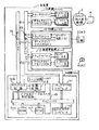
図1は本発明の電話交換装置に係るボタン電話装置の第1の実施の形態を示したブロック図である。1は、アナログ加入者回線2、ボタン電話機(DKT)3、単独電話機(SLT)4に対する通話制御を行う主装置、2は主装置1に収容されているアナログ加入者回線、3は主装置1に収容されているボタン電話機(DKT)、4は主装置1に収容されている単独電話機(SLT)である。
【0020】
ここで、主装置1は、アナログ加入者回線2が接続された局線ユニット11、ボタン電話機3が接続されこれを制御する内線ユニット12、単独電話機4が接続されこれを制御する標準電話機ユニット13、主装置1全体を制御する制御ユニット14、これらユニット間で制御データを伝送するための制御データハイウェイ15、音声データを伝送するためのPCMハイウェイ16を有している。更に、制御ユニット14は制御データハイウェイ15を介して送られてきた制御データを分析する1チップマイクロコンピュータ141、1チップマイクロコンピュータ141の分析結果などに基づいて通話制御及びこれに関連する各種処理を行う16ビットマイクロコンピュータ142、16ビットマイクロコンピュータ142で実行させるプログラムなどを格納しているROM143、16ビットマイクロコンピュータ142などの処理動作に必要な各種データを保存するRAM144、局線ユニット11や内線ユニット12や標準電話機ユニット13と制御ユニット14をPCMハイウェイ16を通して交換接続するタイムスイッチ146、各種トーン信号を発生するトーン回路147、電話を用いた会議などを行うための会議回路148を有している。
【0021】
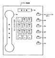
図2は図1に示したボタン電話機3の詳細例を示した平面図である。31c〜31hは内線番号が割当てられたフレキシブルボタン、32はダイヤルパッド、33は各種情報を表示するためのLCD等の表示器、34は送受話器である。ここで、フレキシブルボタン31c〜31gには、504〜500の仮想内線番号が割当てられており、フレキシブルボタン31hには、本ボタン電話機の内線番号である200番が割当てられているものとする。
【0022】
次に本実施の形態の動作について説明する。まず、ボタン電話機3にて仮想内線番号で通話中の時に、第三者から200番に着信があった場合、発信側に話中音を返すか、本電話機に呼び出し音を送出するかを、主装置1に予め設定しなければならない。そのためには、ボタン電話機3より内線番号呼び出し方式機能設定要求を内線ユニット12、制御データハイウェイ15を介して1チップマイクロコンピュータ141に出す。これにより、16ビットマイクロコンピュータ142は1チップマイクロコンピュータ141より内線番号呼び出し方式機能設定要求が出されていることを知り、内線番号呼び出し方式機能設定モードになる。その後、16ビットマイクロコンピュータ142はボタン電話機3から入力されるデータに従って、RAM144にボタン電話機3に対する呼び出し方式の機能設定を行う。
【0023】
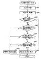
図3は上記した機能設定時の処理の手順を示したフローチャートである。16ビットマイクロコンピュータ142は、まず内線呼び出し方式の機能設定であるかどうかを判定し(ステップ301)、そうでない場合は処理を終了する。一方そうである場合は、ボタン電話機3を介して要求された呼び出し方式が話中音返送(BT)なのか、或いは呼び出し音送出(RBT)なのかを判定し(ステップ302)、話中返送の場合はRAM144にBT(Busy Tone )を設定して処理を終了し(ステップ303)、呼び出し音送出の場合はRAM144にRBT(Ring back tone)を設定して処理を終了する(ステップ304)。
【0024】
これにより、RAM144にBTが設定された場合、以降、ボタン電話機3が仮想内線番号を利用した通話中に、第三者から前記内線番号である200番を利用した着信があった場合、当該第三者に対し話中音を返送する制御が行われる。又、RAM144にRBTが設定された場合、以降、ボタン電話機3が仮想内線番号を利用した通話中に、第三者から前記200番を利用した着信があった場合、このボタン電話機3に呼び出し音が送出される制御が行われる。
【0025】
図4は着信があった際の制御ユニット14の動作を示したフローチャートである。1チップマイクロコンピュータ141は、局線ユニット11、内線ユニット12、標準電話機ユニット13のいずれかから制御データハイウェイ15を介して着信があると、この着信を分析して、16ビットマイクロコンピュータ142に知らせる(ステップ401)。これにより、16ビットマイクロコンピュータ142は着信先を検索する(ステップ402)が、この例ではその着信先をボタン電話機3とする。
【0026】
次に、16ビットマイクロコンピュータ142は、着信先のボタン電話機3の内線番号200番が通話中であるかどうかを判定し(ステップ403)、通話中である場合はステップ408へ飛び、発信側に話中音を送出する(ステップ408)。通話中でない場合、16ビットマイクロコンピュータ142は着信した内線番号がボタン電話機3の内線番号200番であるかどうかを判定する(ステップ404)。
【0027】
ここで、200番でなく例えば仮想内線番号の501番等であった場合は、発信側に呼び出し音を送出する(ステップ407)。200番の内線番号であった場合は、16ビットマイクロコンピュータ142は、ボタン電話機3がいずれかの仮想内線番号を用いて通話中(使用中)であるかどうかを判定する(ステップ405)。
【0028】
ここで、通話中でない場合はステップ407へ飛び、通話中である場合は、RAM144内の呼び出し方式の機能設定データをチェックする(ステップ406)。その結果、BT(話中音の返送)が設定されていることが分かると、16ビットマイクロコンピュータ142は、トーン回路147よりタイムスイッチ回路146、PCMハイウェイ16を介し、更に、例えば局線ユニット16からアナログ加入者回線2側の発信側に話中音を返送し(ステップ408)、処理を終了する。一方、前記RAM144にRBT(呼び出し音の送出)が設定されていた場合、16ビットマイクロコンピュータ142は、トーン回路147よりタイムスイッチ回路146、PCMハイウェイ16を介し、更に内線ユニット12からボタン電話機3に呼び出し音を送出し(ステップ407)、処理を終了する。
【0029】
本実施の形態によれば、ボタン電話機3に対し、主装置1にBT(話中音の返送)を設定しておけば、ボタン電話機3が仮想内線番号で通話中に、別のところから本電話機の内線番号に着信があった場合、主装置1から発信側に話中音を返送することができるため、発信者はボタン電話機3が話中であることを直ちに知り、電話を切るなどの適切な動作を行うことができる。又、ボタン電話機3が仮想内線番号で通話中に、このボタン電話機3から呼び出し音が出力されることがなく、落ち着いて通話を行うことができる。
【0030】
尚、本例では主装置1にRBT(呼び出し音の送出)を設定しておけば、従来通りの呼び出し方式も使用できるため、ボタン電話機3の呼び出し方式のフレキシビリティーを向上させることができる。
【0031】
(第2の実施の形態)
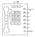
図5は本発明のボタン電話装置の第2の実施の形態を説明する図である。本例のボタン電話機3には、呼び出し方式の変更ボタン35が設けられている他は、図1に示した第1の実施の形態と同様の構成であるため、主装置1などの動作は図1を借用して説明する。
【0032】
次に本実施の形態の動作について図6のフローチャートを参照して説明する。1チップマイクロコンピュータ141は、局線ユニット11、内線ユニット12、標準電話機ユニット13のいずれかから制御データハイウェイ15を介して着信があると、この着信を分析して、16ビットマイクロコンピュータ142に知らせる(ステップ601)。これにより、16ビットマイクロコンピュータ142はステップ602にて着信先を検索するが(ステップ602)、この例ではその着信先をボタン電話機3とする。
【0033】
次に、16ビットマイクロコンピュータ142は、着信先のボタン電話機3の内線番号200番が通話中であるかどうか判定する(ステップ603)。通話中でない場合、16ビットマイクロコンピュータ142は着信した内線番号がボタン電話機3の内線番号200番であるかどうかを判定し(ステップ604)、200番でなく例えば仮想の501番等であった場合は、ステップ607へ飛び、200番の内線番号であった場合はステップ605へ進む。
【0034】
16ビットマイクロコンピュータ142は、ボタン電話機3がいずれかの仮想内線番号を用いて通話中(使用中)であるかどうかを判定し(ステップ605)、通話中でない場合はステップ607へ飛び、通話中である場合は、ボタン電話機3の変更ボタン35がオンかどうかをチェックする(ステップ606)。その結果、変更ボタン35がオンであることが分かると、16ビットマイクロコンピュータ142は、トーン回路147よりタイムスイッチ回路146、PCMハイウェイ16を介して、更に、例えば局線ユニット16からアナログ加入者回線2側の発信側に話中音を返送して処理を終了する(ステップ608)。一方、変更ボタン35がオンでなく、オフであることが分かった場合、16ビットマイクロコンピュータ142は、トーン回路147よりタイムスイッチ回路146、PCMハイウェイ16を介し、更に内線ユニット12からボタン電話機3に呼び出し音を送出して処理を終了する(ステップ607)。
【0035】
本実施の形態によれば、ボタン電話機3の変更ボタン35をオンに予め設定しておけば、ボタン電話機3が仮想内線番号で通話中に、別のところから本電話機の内線番号に着信があった場合、主装置1から発信側に話中音を返送することができるため、発信者はボタン電話機3が話中であることを知り、電話を切るなどの適切な動作を行うことができ、図1に示した第1の実施の形態と同様の効果がある。
【0036】
尚、本例の呼び出し方式の変更ボタン35の操作は、予め行っておくもので、仮想内線番号で通話中に着信があって呼び出し音が発生した時に、前記変更ボタン35をオン、オフしても呼び出し方式の設定は変わらないものとする。
【0037】
(第3の実施の形態)
図7は本発明のボタン電話装置の第3の実施の形態を説明する図である。本例のボタン電話機3には、呼び出し方式の切換ボタン36が設けられている他は、図1に示した第1の実施の形態と同様の構成であるため、主装置1などの動作は図1を借用して説明する。
【0038】
次に本実施の形態の動作について図8のフローチャートを参照して説明する。まず、1チップマイクロコンピュータ141は着信分析を行い、その結果を16ビットマイクロコンピュータ142に知らせる(ステップ801)。これにより、16ビットマイクロコンピュータ142は、前記分析結果に基づいて着信先を検索し(ステップ802)、この例では、その着信先をボタン電話機3とする。次に16ビットマイクロコンピュータ142は、着信先の内線番号200番のボタン電話機3が通話中かどうかを判定し(ステップ803)、通話中でなければ、発信側に呼び出し音を送出する(ステップ804)。一方、通話中であれば、発信側に話中音を返送する(ステップ807)。
【0039】
16ビットマイクロコンピュータ142はステップ804にて、呼び出し音を送出中、発信側が回線を切断するか、又はボタン電話機3がオフフックするかなどの状態変化があると、処理を終了する(ステップ805)。状態変化がない場合、16ビットマイクロコンピュータ142は、ボタン電話機3の切換ボタン36が押下されたかどうかを判定し(ステップ806)、押下されない場合はステップ804に戻り、押下された場合はステップ807へ進み、呼び出し音送出を停止して、発信側に話中音を返送する。ここで、16ビットマイクロコンピュータ142はステップ807にて話中音を返送中に、発信側の回線が切断されたかどうかを判定し、切断されない場合はステップ807に戻り、切断された場合は処理を終了する(ステップ808)。
【0040】
本実施の形態によれば、ボタン電話機3の仮想内線番号を用いて通話中に、別のところから本来の内線番号に着信があって、本電話機3から呼び出し音が発生して、うるさい場合には、切換ボタン36を押下することにより、前記呼び出し音の発生を停止させ、代わりに発信側に話中音を返送することができるため、第1の実施の形態と同様の効果がある。
【0041】
尚、上記した仮想内線番号で通話中に着信があった場合、ボタン電話機3に呼び出し音を送出するモードなのか、或いは発信側に話中音を返送するモードなりかを、前記呼び出し方式切換ボタン36の押下に応じて、ボタン電話機3の表示器33に表示してもよい。あるいは、切換ボタン36に組込まれたLED等の発光素子の点灯か消灯かで、モードの設定状態がわかるようにしてもよい。
【0042】
又、上記のように、仮想内線番号で通話中に切換ボタン36を押して、発信側へ話中音を返送する方式に切り替えた場合、以降、この呼び出し方式が主装置1のRAM144に設定され、その後は、上記した仮想内線番号で通話中に、別のところから着信があった場合、必ず発信側へ話中音を返送する設定に自動的になる構成としてもよい。
【0043】
更に、上記のように仮想内線番号で通話中に、別のところから着信があった場合、切換ボタン36を押下しても、RAM144に切換ボタン36の押下を設定しておくのみで、今回は呼び出し方式は変わらず、このまま呼び出し音が発生し続けるが、次回、仮想内線番号で通話中に、別のところから着信があった場合、前記RAM144の設定をチェックして、切換ボタン36の押下が設定されていると、呼び出し音の送出の代わりに、話中音を発信側に返送するという制御を行ってもよい。
【0044】
この場合、仮想内線番号で通話中に前記呼び出し音が発生している時以外に、前記切換ボタン36を押下すると、これを検出して16ビットマイクロコンピュータ142はRAM144に設定してある前記切換ボタン36の押下設定をクリアーして、その後、仮想内線番号で通話中に、別のところから着信があった場合、ボタン電話機3に呼び出し音を送出する制御に装置に戻すようにするものとする。
【0045】
(第4の実施の形態)
図9は本発明のボタン電話装置の第4の実施の形態を説明する図である。本例では、単独電話機4の代わりに、ボイスメール装置5が接続されている。又、ボタン電話機3には、図7の実施の形態で説明したのと同様に呼び出し方式の切換ボタン電話36が設けられているため、以降、図7を借用して説明する。
【0046】
次に本実施の形態の動作について図10のフローチャートを参照して説明する。ステップ101〜106及びステップ108の動作は、図8に示したステップ801〜806及びステップ808の動作と同一である。異なるところはステップ107の動作である。即ち、図9の制御ユニット14の16ビットマイクロコンピュータ142は、ボタン電話機3が仮想内線番号で通話中に、別のところから着信があった場合、この発信側と、標準電話機ユニット13をタイムスイッチ回路146により、PCMハイウェイ16を介して接続すると共に、制御データハイウェイ15より起動データを標準電話機ユニット13に送ってボイスメール装置5を起動する(ステップ107)。これにより、ボイスメール装置5から、例えば「本電話機は通話中でありますでの、一旦電話を切ってしばらくたってからおかけ直し下さい」というようなボイスメールを発信側に送出する。
【0047】
本実施の形態によれば、ボタン電話機3の仮想内線番号を用いて通話中に、別のところから本来の内線番号に着信があって、本電話機3から呼び出し音が発生して、うるさい場合には、切換ボタン36を押下することにより、前記呼び出し音の発生を停止させ、代わりに発信側に通話中であることを知らせるボイスメールを返送することができるため、発信側にボタン電話機3の状況を明確に伝えることができる。他の効果は第1の実施の形態と同様である。
【0048】
尚、前記呼び出し音の発生を停止させ、代わりに発信側に通話中であることを知らせるボイスメールを返送する構成は、第1、第2の実施の形態にても、同様にして構成することができ、同様の効果がある。
【0049】
さらに、ボイスメールを返送するだけでなく、留守番電話の様に発信者のメッセージをも録音させるように構成してもよい。この様な構成にすれば、伝言を受付けることができ便利である。
【0050】
(第5の実施の形態)
本実施の形態は図1及び図2に示したボタン電話装置と同様の構成を有し、主装置1に呼び出し方式を設定する方法が異なる。第3の実施の形態ではボタン電話機3の呼び出し方式の切換ボタン36により呼び出し方式の切り換えを行うものであったが、本実施の形態ではボタン電話機3から特定番号をダイヤルすることにより呼び出し方式の切り換えを行う。
【0051】
次に本実施の形態の動作について図11のフローチャートを参照して説明する。まず、1チップマイクロコンピュータ141は着信分析を行い、その結果を16ビットマイクロコンピュータ142に知らせる(ステップ111)。これにより、16ビットマイクロコンピュータ142は、前記分析結果に基づいて着信先を検索し(ステップ112)、この例では、その着信先をボタン電話機3とし、ステップ113にてその着信先ボタン電話機3の表示器33に発信者番号を表示させる(ステップ113)。次に16ビットマイクロコンピュータ142は、着信先の内線番号200番のボタン電話機3が通話中かどうかを判定し(ステップ114)、通話中でなければ、発信側に呼び出し音を送出する(ステップ115)。一方、通話中であれば、発信側に話中音を返送する(ステップ118)。
【0052】
16ビットマイクロコンピュータ142はステップ115にて、呼び出し音を送出中、発信側が回線を切断するか、又はボタン電話機3がオフフックするかなどの状態変化があると、処理を終了する(ステップ116)。状態変化がない場合、16ビットマイクロコンピュータ142は、ボタン電話機3で特定番号がダイアルされたかどうかを判定し(ステップ117)、ダイアルされない場合はステップ115に戻り、ダイアルされた場合はステップ118へ進み、呼び出し音送出を停止して、発信側に話中音を返送する。ここで、16ビットマイクロコンピュータ142はステップ118にて話中音を返送中に、発信側の回線が切断されたかどうかを判定し、切断されない場合はステップ118に戻り、切断された場合は処理を終了する(ステップ119)。
【0053】
本実施の形態によれば、ボタン電話機3の仮想内線番号を用いて通話中に、別のところから本来の内線番号に着信があって、本電話機3から呼び出し音が発生して、うるさい場合には、特定番号をダイアルすることにより、前記呼び出し音の発生を停止させ、代わりに発信側に話中音を返送することができるため、第1の実施の形態と同様の効果がある。
【0054】
尚、上記した仮想内線番号で通話中に着信があった場合、ボタン電話機3に呼び出し音を送出するモードなのか、或いは発信側に話中音を返送するモードなりかを、前記特定番号のダイアルに応じて、ボタン電話機3の表示器33に表示してもよい。
【0055】
又、上記のように、仮想内線番号で通話中に特定番号をダイアルして、発信側へ話中音を返送する方式に切り替えた場合、以降、この呼び出し方式が主装置1のRAM144に設定され、その後は、上記した仮想内線番号で通話中に、別のところから着信があった場合、必ず発信側へ話中音を返送する設定に自動的になる構成としてもよい。
【0056】
更に、上記のように仮想内線番号で通話中に、別のところから着信があった場合、特定番号をダイアルしても、RAM144に特定番号のダイアルを設定しておくのみで、今回は呼び出し方式は変わらず、このまま呼び出し音が発生し続けるが、次回、仮想内線番号で通話中に、別のところから着信があった場合、前記RAM144の設定をチェックして、特定番号のダイアルが設定されていると、呼び出し音の送出の代わりに、話中音を発信側に返送するという制御を行ってもよい。
【0057】
この場合、仮想内線番号で通話中に前記呼び出し音が発生している時以外に、前記特定番号のダイアルを押下すると、これを検出して16ビットマイクロコンピュータ142はRAM144に設定してある前記特定番号のダイアル設定をクリアーして、その後、仮想内線番号で通話中に、別のところから着信があった場合、ボタン電話機3に呼び出し音を送出する制御に装置に戻すようにするものとする。
【0058】
(第6の実施の形態)
本実施の形態は図1及び図2に示したボタン電話装置と同様の構成を有し、主装置1に呼び出し方式を設定する方式が異なる。上記実施の形態では発信側が誰であるかにかかわらず、ボタン電話機3の呼び出し方式をBTまたはRBTに設定するものであった。本実施の形態では、上記第1乃至第5の実施の形態において、発信者番号対応に呼び出し方式の設定ができるようにしたものである。
【0059】
図12は、RAM144に設定するメモリマップである。例えば、発信者番号AはRBTに設定し、発信者番号BとCはBTに設定するといった様に、予め発信者番号対応に呼び出し方式の設定をする。ボタン電話機3に着信があった場合、このメモリマップが参照され、発信者番号Aからの着信のみ呼び出し音を鳴らし、発信者番号BやCからの着信に対しては呼び出し音は鳴らさず発信側に話中音を返送する。
【0060】
本実施の形態によれば、重要な取引先等からの着信のみを受付けることができ、不要な着信を排除することができるという効果を有する。
なお、上記実施の形態ではRAM144のメモリマップにRBTとBTの双方の発信者番号を登録するよう構成したが、RBTまたはBTの一方のみを登録するよう構成し、登録されてない発信者番号に対しては他方の呼び出し設定となる構成としてもよい。
【0061】
(第7の実施の形態)
本実施の形態は上記第6の実施の形態の変形例であり、発信者番号対応に呼び出し方式の設定ができるようにしたものであるが、RBTの登録がなされている発信者番号に優先度を付与した構成を有する。
【0062】
図13は、RAM144に設定するメモリマップである。例えば、発信者番号A、B、CはRBTに設定されており、それぞれ優先度1、優先度2、優先度3が付与されている。ボタン電話機3に着信があった場合、このメモリマップが参照され、発信者番号A、B、Cからの着信のみ呼び出し音を鳴らし、その他の発信者番号からの着信に対しては呼び出し音は鳴らさず発信側に話中音を返送する。ここで、発信者番号Bと仮想内線番号を用いて通話中に、発信者番号Cから内線番号に着信があった場合、メモリマップの優先度の比較が行われるが、発信者番号Bの方が優先度が高いため、発信者番号Cに対しては話中音を返送する。また、発信者番号Bと仮想内線番号を用いて通話中に、発信者番号Aから内線番号に着信があった場合、メモリマップの優先度の比較が行われるが、発信者番号Aの方が優先度が高いため、呼び出し音を送出させる。
【0063】
本実施の形態によれば、着信させたい発信者を選択することができるとともに、更に着信させたい発信者の優先度に応じて適切な処置を取り得るという効果を有する。
【0064】
(第8の実施の形態)
本実施の形態は図14に示すボタン電話装置であり、保守ターミナル150が接続されている以外は図1 と同様の構成を有する。すなわち、上記実施の形態ではボタン電話機3から呼び出し方式の設定を行うものであるが、本実施例では、ボタン電話機3とは別に設けられた保守ターミナル150にある入力手段により行う。その他の動作は上記実施の形態と同様なので説明を省略する。
本実施の形態によれば、ボタン電話機3毎の呼び出し方式の設定を一括して行うことができるという効果を有する。
【0065】
(第9の実施の形態)
本実施の形態は図15に示すボタン電話装置であり、ボタン電話機3による通話とは別に制御ユニット14とのデータの送受ができる情報端末装置例えばパーソナルコンピュータPCが接続されている以外は図1と同様の構成を有する。すなわち、上記実施の形態ではボタン電話機3から呼び出し方式の設定を行うものであるが、本実施の形態では、ボタン電話機3に接続されたパーソナルコンピュータPCからの操作により行う。その他の動作は上記第1乃至第7の実施の形態と同様なので説明を省略する。
【0066】
本実施の形態によれば、ボタン電話機3毎の呼び出し方式の設定を情報端末装置を用いて行うことができるという効果を有する。
なお、上記実施の形態では、情報端末装置がボタン電話機3に接続されている例を示したがこれに限定されない。例えば、図16に示すように、アナログ回線網2を介して接続されたパーソナルコンピュータPCからの操作で呼び出し方式の設定を行うように構成してもよい。
【0067】
【発明の効果】
本発明によれば、着信先のボタン電話機が仮想内線番号を用いて通話中の時に当該ボタン電話機の内線番号に着信があった場合、この内線番号の発信側へ話中であることを知らせることができる。
【図面の簡単な説明】
【図1】本発明の電話交換装置の第1の実施の形態を示したブロック図。
【図2】図1に示したボタン電話機の詳細例を示した平面図。
【図3】図1に示した主装置に呼び出し方式の機能設定をする際の処理手順を示したフローチャート。
【図4】図1に示したボタン電話装置の呼び出し動作手順を示したフローチャート。
【図5】本発明のボタン電話装置の第2の実施の形態を説明する図。
【図6】図5に示したボタン電話装置の呼び出し動作手順を示したフローチャート。
【図7】本発明のボタン電話装置の第3の実施の形態を説明する図。
【図8】図7に示したボタン電話装置の呼び出し動作手順を示したフローチャート。
【図9】本発明のボタン電話装置の第4の実施の形態を説明するブロック図。
【図10】図9に示したボタン電話装置の呼び出し動作手順を示したフローチャート。
【図11】本発明のボタン電話装置の第5の実施の形態の動作手順を示したフローチャート。
【図12】本発明のボタン電話装置の第6の実施の形態における主装置のメモリマップ。
【図13】本発明のボタン電話装置の第7の実施の形態における主装置のメモリマップ。
【図14】本発明のボタン電話装置の第8の実施の形態を説明するブロック図。
【図15】本発明のボタン電話装置の第9の実施の形態を説明するブロック図。
【図16】本発明のボタン電話装置の第9の実施の形態の変形を説明するブロック図。
【符号の説明】
1 主装置
2 アナログ加入者回線
3 ボタン電話機(DKT)
4 単独電話機(SLT)
11 局線ユニット
12 内線ユニット
13 標準電話機ユニット
14 制御ユニット
15 制御データハイウェイ
16 PCMハイウェイ
31c〜31h フレキシブルボタン
32 ダイヤルパッド
33 表示器
34 送受話器
35 変更ボタン
36 切換ボタン
141 1チップマイクロコンピュータ
142 16ビットマクロコンピュータ
144 RAM
146 タイムスイッチ回路
147 トーン回路[0001]
BACKGROUND OF THE INVENTION
The present invention relates to control of a call when there is a call from a third party during a call.
[0002]
[Prior art]
Among the conventional telephone exchange apparatuses, a key telephone apparatus can assign a virtual extension number to an extension key telephone. Here, the virtual extension number is a number assigned to an extension having no physical accommodation position and telephone unit. For example, extension numbers such as 500 and 501 assigned to other extension terminals can be assigned as virtual extension numbers to a key telephone to which an extension number of 200 is assigned. Such a button telephone can normally make a call using the original extension number of 200, but can also make a call using the virtual extension number of 500 or 501.
[0003]
Next, extension number calling processing of a conventional key telephone apparatus will be described. When there is an incoming call on an extension, first, the incoming call analysis is performed based on the extension number, and the called party is searched. Next, it is determined whether or not the extension number button telephone is busy, and if not, a ringing tone is transmitted to the caller and the process is terminated. On the other hand, if the call is in progress, the busy tone is returned to the caller and the process is terminated.
Therefore, when a call is made using the extension number of the key telephone, which is 200 in the above example, even if there is an incoming call from another place, the busy tone is returned to the caller. Thus, the caller will know that he is busy and hang up.
[0004]
On the other hand, if the key telephone receives an incoming call from another location during a call using the
[0005]
[Problems to be solved by the invention]
As mentioned above, when a call is received from another location during a call using a virtual extension number other than the extension number originally assigned to a button telephone, the extension number originally assigned is vacant. Therefore, a ringing tone is output from this key telephone, but since this call cannot be answered, there is a problem that the ringing tone is turned off and the call cannot be continued calmly. In addition, the caller can understand that it is difficult to answer the call, but since the called party does not know that he / she is busy, the situation cannot be accurately grasped, and a wasteful waiting time is wasted. .
[0006]
The present invention relates to a button telephone device capable of taking an appropriate measure for a caller side when an incoming call using an extension number is received from another place during a call using a virtual extension number, and an incoming call reception method thereof The purpose is to provide.
[0007]
[Means for Solving the Problems]
According to a first aspect of the present invention, in a button telephone apparatus having a function capable of assigning a virtual extension number in addition to an extension number to a telephone, there is an incoming call during a call using the virtual extension number on the telephone. Setting means for setting back the busy tone to the caller in the event of a call, and when the telephone number is received during a call using the virtual extension number on the telephone, the setting contents of the setting means are If the setting is made so that the busy tone is returned to the calling side, a busy tone returning means for returning the busy tone to the calling side instead of sending a ringing tone to the telephone is provided. This is a button telephone device.
[0008]
With such a configuration, if the setting means is configured to return a busy tone to the calling side when there is an incoming call during the call using the virtual extension number on the key telephone, the busy tone return is performed. The means performs a control to return a busy tone to the caller instead of sending a ringing tone to the key phone when an incoming call is received using the virtual extension number on the key phone.
[0009]
According to a second invention described in the present application, in a button telephone apparatus having a function of assigning a virtual extension number in addition to an extension number to a telephone, there is an incoming call during a call using the virtual extension number on the telephone. If there is an incoming call to the extension number during a call using the virtual extension number on the telephone, check the setting contents of the setting means When the voice mail is set to be returned to the calling side, voice mail returning means for returning the voice mail to the calling side instead of sending a ring tone to the telephone is provided. It is a button telephone device.
[0010]
With this configuration, when there is an incoming call during a call using the virtual extension number on the key telephone, the voice mail return means stops sending the ringing tone to the key telephone, Return a voice mail to the caller that the phone is busy.
[0011]
According to a third aspect of the present invention, in a button telephone apparatus having a function of assigning a virtual extension number in addition to an extension number to a telephone, there is an incoming call during a call using the virtual extension number on the telephone. If there is an incoming call to the extension number during a call using the virtual extension number on the telephone, the setting means for setting the voice mail back to the calling side and recording the message on the calling side If the setting contents of the setting means are checked and voice mail is sent back to the calling side and the message on the calling side is recorded, the voice mail is sent instead of sending a ring tone to the telephone. And a message recording means for recording the message on the calling side.
[0012]
With this configuration, when there is an incoming call during a call using the virtual extension number on the key telephone, the message recording means stops sending the ringing tone to the key telephone, and makes a call instead. Record your message.
[0013]
According to a fourth aspect of the present invention, in the button telephone apparatus having a function of assigning a virtual extension number in addition to the extension number to the telephone, the extension number is used during a call using the virtual extension number on the telephone. The setting means for returning the busy tone to the caller when there is an incoming call, setting means for turning on / off for each caller, and receiving the call at the extension number during the call using the virtual extension number at the telephone If the setting of the setting means is checked and the setting for returning the busy tone to the calling side is ON, the busy tone is sent to the calling side instead of sending the ringing tone to the telephone. A button telephone device comprising a busy-sound return means for returning.
[0014]
With such a configuration, when the setting unit makes an incoming call during a call using the virtual extension number on the key telephone, if the setting is made so that the busy tone is returned to each calling side, the busy tone Only when there is an incoming call from the caller whose setting is to send back, a control is performed to return a busy tone to the caller instead of sending a ring tone to the key telephone.
[0015]
According to a fifth aspect of the present invention, in the button telephone apparatus having a function of assigning a virtual extension number in addition to the extension number to the telephone, the extension number is used during a call using the virtual extension number on the telephone. Setting means for performing a setting for returning a busy tone to the calling side when an incoming call is received, and setting the priority for each calling side, and the extension number during a call using the virtual extension number on the telephone When there is an incoming call, the setting contents of the setting means are checked, and only when the priority of the extension number on the calling side is lower than the priority on the calling side of the virtual extension number, a ring tone is sent to the telephone. Instead of this, a busy telephone return device for returning a busy tone to the caller is provided.
[0016]
With this configuration, when there is an incoming call during a call using the virtual extension number on the key telephone, the priority of the calling party is compared, and the priority of the calling party that has arrived later is received first. When the priority is lower than the caller's priority, control is performed to return a busy tone to the caller that has received the call.
A sixth invention described in the present application is a button telephone device characterized in that the setting means of the first to fifth inventions is an input means provided separately from the telephone.
[0017]
With such a configuration, settings for a plurality of key telephones can be performed collectively, or setting contents can be easily registered or changed.
A seventh invention described in the present application is a button telephone device characterized in that the setting means of the first to fifth inventions is a predetermined key provided on the telephone.
With such a configuration, setting is made to return a busy tone or voice mail by operating a predetermined key of the key telephone.
[0018]
An eighth invention described in the present application is an incoming call reception method for a button telephone apparatus having a function capable of assigning a virtual extension number in addition to an extension number to a telephone, wherein the destination telephone is using the extension number If the extension is in use, a busy tone is sent back to the caller, and it is determined whether the destination telephone is using the virtual extension, and the virtual extension is in use. If there is, the incoming call reception method of the key telephone device is characterized in that a busy tone or voice mail is returned to the caller.
By such a method, if the destination key telephone is in use, a busy tone or voice mail is returned to the caller.
[0019]
DETAILED DESCRIPTION OF THE INVENTION
Hereinafter, embodiments of the present invention will be described with reference to the drawings.
(First embodiment)
FIG. 1 is a block diagram showing a first embodiment of a button telephone apparatus according to the telephone exchange apparatus of the present invention.
[0020]
Here, the
[0021]
FIG. 2 is a plan view showing a detailed example of the
[0022]
Next, the operation of the present embodiment will be described. First, if a third party receives an incoming call to the
[0023]
FIG. 3 is a flowchart showing a procedure of processing at the time of the above-described function setting. The 16-
[0024]
As a result, when BT is set in the
[0025]
FIG. 4 is a flowchart showing the operation of the control unit 14 when there is an incoming call. When there is an incoming call from the office line unit 11, extension unit 12, or standard telephone unit 13 via the
[0026]
Next, the 16-
[0027]
Here, if the number is not the
[0028]
If the call is not in progress, the process jumps to step 407. If the call is in progress, the function setting data of the calling method in the
[0029]
According to the present embodiment, if BT (return of busy tone) is set in the
[0030]
In this example, if RBT (transmission of ringing tone) is set in the
[0031]
(Second Embodiment)
FIG. 5 is a diagram for explaining a second embodiment of the key telephone apparatus of the present invention. The
[0032]
Next, the operation of the present embodiment will be described with reference to the flowchart of FIG. When there is an incoming call from the office line unit 11, extension unit 12, or standard telephone unit 13 via the
[0033]
Next, the 16-
[0034]
The 16-
[0035]
According to the present embodiment, if the
[0036]
Note that the operation of the
[0037]
(Third embodiment)
FIG. 7 is a diagram for explaining a third embodiment of the key telephone apparatus of the present invention. The
[0038]
Next, the operation of the present embodiment will be described with reference to the flowchart of FIG. First, the one-
[0039]
In
[0040]
According to the present embodiment, during a call using the virtual extension number of the
[0041]
When there is an incoming call during a call with the above virtual extension number, the call mode switching button determines whether the mode is a mode for sending a ringing tone to the
[0042]
Further, as described above, when the switching button 36 is pressed during a call with a virtual extension number and the system is switched to a method of returning a busy tone to the calling side, this calling method is set in the
[0043]
Further, when a call is received from another place during a call with a virtual extension as described above, even if the switch button 36 is pressed, only pressing of the switch button 36 is set in the
[0044]
In this case, when the switching button 36 is pressed except when the ringing tone is generated during a call with a virtual extension number, the 16-
[0045]
(Fourth embodiment)
FIG. 9 is a diagram for explaining a fourth embodiment of the key telephone apparatus of the present invention. In this example, a
[0046]
Next, the operation of the present embodiment will be described with reference to the flowchart of FIG. The operations of
[0047]
According to the present embodiment, during a call using the virtual extension number of the
[0048]
It should be noted that the configuration for stopping the generation of the ringing tone and returning the voice mail notifying the caller that the call is in progress is similarly configured in the first and second embodiments. Have the same effect.
[0049]
Furthermore, it may be configured not only to return the voice mail but also to record the caller's message like an answering machine. This configuration is convenient because it can accept messages.
[0050]
(Fifth embodiment)
This embodiment has the same configuration as the button telephone apparatus shown in FIGS. 1 and 2, and the method for setting the calling method in the
[0051]
Next, the operation of the present embodiment will be described with reference to the flowchart of FIG. First, the one-
[0052]
In
[0053]
According to the present embodiment, during a call using the virtual extension number of the
[0054]
When there is an incoming call during a call with the above-described virtual extension number, whether the mode is a mode for sending a ringing tone to the
[0055]
In addition, as described above, when switching to a method of dialing a specific number during a call with a virtual extension number and returning a busy tone to the calling side, this calling method is set in the
[0056]
Further, when a call is received from another location during a call with a virtual extension number as described above, even if the specific number is dialed, only the dial of the specific number is set in the
[0057]
In this case, except when the ringing tone is generated during a call with a virtual extension number, when the dial of the specific number is pressed, this is detected and the 16-
[0058]
(Sixth embodiment)
This embodiment has the same configuration as the button telephone apparatus shown in FIGS. 1 and 2, and the system for setting the calling system in the
[0059]
FIG. 12 is a memory map set in the
[0060]
According to the present embodiment, it is possible to accept only incoming calls from important business partners and the like, and it is possible to eliminate unnecessary incoming calls.
In the above embodiment, both the RBT and BT caller numbers are registered in the memory map of the
[0061]
(Seventh embodiment)
The present embodiment is a modification of the sixth embodiment, and can set the call method corresponding to the caller number. However, priority is given to the caller number registered in the RBT. It has the structure which gave.
[0062]
FIG. 13 is a memory map set in the
[0063]
According to the present embodiment, it is possible to select a caller who wants to receive a call and to take an appropriate action according to the priority of the caller who wants to receive a call.
[0064]
(Eighth embodiment)
This embodiment is a button telephone apparatus shown in FIG. 14, and has the same configuration as that of FIG. 1 except that a
According to the present embodiment, it is possible to collectively set the calling method for each
[0065]
(Ninth embodiment)
This embodiment is a button telephone apparatus shown in FIG. 15 and is the same as that shown in FIG. 1 except that an information terminal device, such as a personal computer PC, that can send and receive data to and from the control unit 14 is connected separately from the
[0066]
According to the present embodiment, there is an effect that the setting of the calling method for each
In the above embodiment, an example in which the information terminal device is connected to the
[0067]
【The invention's effect】
According to the present invention, when an incoming call is made to the extension number of the key telephone when the destination key telephone is busy using a virtual extension number, the caller of the extension number is notified that the call is busy. Can do.
[Brief description of the drawings]
FIG. 1 is a block diagram showing a first embodiment of a telephone exchange apparatus according to the present invention.
FIG. 2 is a plan view showing a detailed example of the key telephone shown in FIG. 1;
FIG. 3 is a flowchart showing a processing procedure when setting a function of a calling method in the main apparatus shown in FIG. 1;
FIG. 4 is a flowchart showing a calling operation procedure of the key telephone apparatus shown in FIG. 1;
FIG. 5 is a diagram for explaining a second embodiment of a button telephone device according to the present invention;
6 is a flowchart showing a calling operation procedure of the key telephone apparatus shown in FIG. 5;
FIG. 7 is a diagram for explaining a third embodiment of a button telephone apparatus according to the present invention;
FIG. 8 is a flowchart showing a calling operation procedure of the key telephone apparatus shown in FIG. 7;
FIG. 9 is a block diagram for explaining a fourth embodiment of the button telephone device of the present invention;
10 is a flowchart showing a calling operation procedure of the key telephone apparatus shown in FIG. 9;
FIG. 11 is a flowchart showing the operation procedure of the fifth embodiment of the key telephone device of the present invention;
FIG. 12 is a memory map of the main device in the sixth embodiment of the button telephone device of the present invention;
FIG. 13 is a memory map of the main device in the seventh embodiment of the key telephone device of the present invention;
FIG. 14 is a block diagram for explaining an eighth embodiment of a button telephone apparatus according to the present invention;
FIG. 15 is a block diagram for explaining a ninth embodiment of the key telephone apparatus of the present invention;
FIG. 16 is a block diagram for explaining a modification of the ninth embodiment of the button telephone device of the present invention;
[Explanation of symbols]
1 Main unit
2 Analog subscriber line
3-button telephone (DKT)
4 Single phone (SLT)
11 Station line unit
12 Extension unit
13 Standard telephone unit
14 Control unit
15 Control data highway
16 PCM Highway
31c ~ 31h Flexible button
32 Dial pad
33 Display
34 Handset
35 Change button
36 Select button
141 One-chip microcomputer
142 16-bit macro computer
144 RAM
146 Time switch circuit
147 Tone circuit
Claims (12)
前記電話機にて前記仮想内線番号を用いて通話中に着信があった場合に発信側へ話中音を返送する設定を行う設定手段と、
前記電話機にて前記仮想内線番号を用いて通話中であるか否かを判断する判断手段と、
前記電話機にて前記仮想内線番号を用いて通話中に前記内線番号に着信があった場合、前記設定手段の設定に従って、前記電話機に読出し音を送出する代わりに、話中音を前記発信側に返送する話中音返送手段と
を備えることを特徴とするボタン電話装置。It is a button telephone device that can assign a virtual extension number to a telephone in addition to an extension number, and has a function that enables a telephone call using the extension number and the virtual extension number ,
A setting means for performing a setting for returning a busy tone to the calling side when there is an incoming call during a call using the virtual extension number on the telephone;
Determining means for determining whether the telephone is busy using the virtual extension number;
When an incoming call arrives at the extension number during a call using the virtual extension number at the telephone, a busy sound is sent to the calling side instead of sending a readout sound to the telephone according to the setting of the setting means. key telephone system characterized by comprising a busy tone returning means for returning.
前記電話機にて前記仮想内線番号を用いて通話中に着信があった場合に発信側へボイスメールを返送する設定を行う設定手段と、
前記電話機にて前記仮想内線番号を用いて通話中であるか否かを判断する判断手段と、
前記電話機にて前記仮想内線番号を用いて通話中に前記内線番号に着信があった場合、前記設定手段の設定に従って、前記電話機に呼び出し音を送出する代わりに、ボイスメールを前記発信側に返送するボイスメール返送手段と
を備えることを特徴とするボタン電話装置。It is a button telephone device that can assign a virtual extension number to a telephone in addition to an extension number, and has a function that enables a telephone call using the extension number and the virtual extension number ,
A setting means for performing a setting to return a voice mail to the calling side when there is an incoming call during a call using the virtual extension number on the telephone;
Determining means for determining whether the telephone is busy using the virtual extension number;
When an incoming call arrives at the extension number during a call using the virtual extension number at the telephone, a voice mail is returned to the calling party instead of sending a ring tone to the telephone according to the setting of the setting means. key telephone system characterized in that it comprises a voice mail returning means for.
前記電話機にて前記仮想内線番号を用いて通話中に着信があった場合に発信側へボイスメールを返送し且つ発信側のメッセージを録音する設定を行う設定手段と、
前記電話機にて前記仮想内線番号を用いて通話中であるか否かを判断する判断手段と、
前記電話機にて前記仮想内線番号を用いて通話中に前記内線番号に着信があった場合、前記設定手段の設定に従って、前記電話機に呼び出し音を送出する代わりに、ボイスメールを前記発信側に返送し且つ発信側のメッセージを録音するメッセージ録音手段と
を備えることを特徴とするボタン電話装置。It is a button telephone device that can assign a virtual extension number to a telephone in addition to an extension number, and has a function that enables a telephone call using the extension number and the virtual extension number ,
A setting means for performing a setting to return a voice mail to the calling side and record a message on the calling side when there is an incoming call during a call using the virtual extension number on the telephone;
Determining means for determining whether the telephone is busy using the virtual extension number;
When an incoming call arrives at the extension number during a call using the virtual extension number at the telephone, a voice mail is returned to the calling party instead of sending a ring tone to the telephone according to the setting of the setting means. key telephone system characterized in that it comprises a message recording means to and Record originating message.
を特徴とする請求項1乃至請求項3記載のボタン電話装置。The button telephone apparatus according to claim 1, wherein:
を特徴とする請求項1乃至請求項3記載のボタン電話装置。The button telephone apparatus according to claim 1, wherein:
を特徴とする請求項1乃至請求項3記載のボタン電話装置。The button telephone apparatus according to claim 1, wherein:
をさらに備えることを特徴とする請求項1乃至請求項3のいずれかに記載のボタン電話装置。When there is an incoming call to the extension number during a call using the virtual extension number in the phone, to claim 1, characterized in that it further comprises an incoming call display means for displaying the incoming call to the said extension The button telephone apparatus according to claim 3 .
を特徴とする請求項8に記載のボタン電話装置。9. The button telephone apparatus according to claim 8, wherein the incoming call display means displays a telephone number of a caller of the extension number.
を特徴とする請求項 1 記載のボタン電話装置。 The setting by the setting means should be performed for each caller ID
2. The button telephone apparatus according to claim 1, wherein:
前記話中音返送手段は、前記電話機にて前記仮想内線番号を用いて通話中に前記内線番号に着信があった場合、前記設定手段の設定内容に従って、前記内線番号への発信側の発信者番号の優先度が前記仮想内線番号への発信側の発信者番号の優先度よりも低い時に、前記電話機に呼び出し音を送出する代わりに、話中音を前記内線番号への発信側に返送することThe busy tone return means, when there is an incoming call to the extension number during a call using the virtual extension number at the telephone, according to the setting contents of the setting means, Instead of sending a ring tone to the telephone when the priority of the number is lower than the priority of the caller number of the caller to the virtual extension number, a busy tone is returned to the caller of the extension number thing
を特徴とする請求項Claims characterized by 11 記載のボタン電話装置。The button telephone device described.
着信先の前記電話機が内線番号を用いて通話中に着信があった場合、発信側へ話中音を返送し、
着信先の前記電話機が仮想内線番号を用いて通話中に前記内線番号に着信があった場合、その場合に発信側へ話中音を返送するか否かが設定された設定内容に従って発信側へ話中音を返送すること
を特徴とするボタン電話装置の着信受付方法。An incoming call reception method for a button telephone apparatus that can assign a virtual extension number to a telephone in addition to an extension number, and has a function that enables a telephone call using the extension number and the virtual extension number ,
If the destination telephone receives an incoming call using an extension number, it returns a busy tone to the calling party,
If the destination telephone receives a call using the virtual extension number and the extension number is received , in that case, whether or not to return a busy tone to the calling side is set according to the set contents . An incoming call reception method for a button telephone device, characterized by returning a busy tone.
Priority Applications (1)
| Application Number | Priority Date | Filing Date | Title |
|---|---|---|---|
| JP06288998A JP3737273B2 (en) | 1997-03-13 | 1998-03-13 | Button telephone apparatus and incoming call reception method thereof |
Applications Claiming Priority (5)
| Application Number | Priority Date | Filing Date | Title |
|---|---|---|---|
| JP5867497 | 1997-03-13 | ||
| JP9-58674 | 1997-03-13 | ||
| JP9-77338 | 1997-03-13 | ||
| JP7733897 | 1997-03-28 | ||
| JP06288998A JP3737273B2 (en) | 1997-03-13 | 1998-03-13 | Button telephone apparatus and incoming call reception method thereof |
Publications (2)
| Publication Number | Publication Date |
|---|---|
| JPH10327437A JPH10327437A (en) | 1998-12-08 |
| JP3737273B2 true JP3737273B2 (en) | 2006-01-18 |
Family
ID=27296649
Family Applications (1)
| Application Number | Title | Priority Date | Filing Date |
|---|---|---|---|
| JP06288998A Expired - Fee Related JP3737273B2 (en) | 1997-03-13 | 1998-03-13 | Button telephone apparatus and incoming call reception method thereof |
Country Status (1)
| Country | Link |
|---|---|
| JP (1) | JP3737273B2 (en) |
Families Citing this family (3)
| Publication number | Priority date | Publication date | Assignee | Title |
|---|---|---|---|---|
| JP2000308132A (en) | 1999-04-19 | 2000-11-02 | Nec Corp | Private exchange system |
| JP5196575B2 (en) * | 2009-02-12 | 2013-05-15 | Necインフロンティア株式会社 | Exchange, extension telephone system, caller information display method used therefor, and program thereof |
| JP5568050B2 (en) * | 2011-04-18 | 2014-08-06 | 住友電気工業株式会社 | Relay device and relay method |
-
1998
- 1998-03-13 JP JP06288998A patent/JP3737273B2/en not_active Expired - Fee Related
Also Published As
| Publication number | Publication date |
|---|---|
| JPH10327437A (en) | 1998-12-08 |
Similar Documents
| Publication | Publication Date | Title |
|---|---|---|
| US6628768B1 (en) | System and method of responding to an incoming call while conferencing | |
| GB2325114A (en) | Call switching in private branch exchange | |
| JP3080262B2 (en) | Exchange control unit | |
| JPH06133038A (en) | Holding display system for multi-function telephone set | |
| JP3737273B2 (en) | Button telephone apparatus and incoming call reception method thereof | |
| JPH0738629A (en) | Telephone set with incoming call reply function in busy state | |
| KR19990060612A (en) | How to automatically send voice message to specific caller | |
| JPS6370648A (en) | Interruption communication telephone set | |
| JPH06232962A (en) | Mobile communication terminal equipment | |
| JP4402344B2 (en) | Button telephone system, button telephone apparatus and program | |
| JP2807770B2 (en) | Telephone device and incoming call notification method during communication | |
| JP2898085B2 (en) | Telephone exchange system with waiting response function | |
| JPH11163972A (en) | Telephone set with transfer function | |
| JP2002185617A (en) | Incoming call service system during call and its method | |
| JPH06232975A (en) | Private branch exchange | |
| JP2000115371A (en) | Method of having provision for caller telephone number notice, its telephone system and information storage medium | |
| KR19990069725A (en) | How to Generate Incoming Ring by Caller in Integrated Telephone Network | |
| JP2001025042A (en) | Key telephone system | |
| JPH06237297A (en) | Communication system with holding function | |
| JPH05300244A (en) | Call waiting device in exchange | |
| JPS63144645A (en) | Memorandom communication system | |
| JPH11275230A (en) | Choice designation service dealing exchange, callee designation service dealing exchange, choice designating method and storage medium | |
| JP2000092208A (en) | Private branch exchange and telephone switching method | |
| JPH04269061A (en) | Pushbutton telephone set | |
| JPH06232973A (en) | Private branch exchange |
Legal Events
| Date | Code | Title | Description |
|---|---|---|---|
| RD02 | Notification of acceptance of power of attorney |
Free format text: JAPANESE INTERMEDIATE CODE: A7422 Effective date: 20050414 |
|
| A977 | Report on retrieval |
Free format text: JAPANESE INTERMEDIATE CODE: A971007 Effective date: 20050510 |
|
| A131 | Notification of reasons for refusal |
Free format text: JAPANESE INTERMEDIATE CODE: A131 Effective date: 20050513 |
|
| RD04 | Notification of resignation of power of attorney |
Free format text: JAPANESE INTERMEDIATE CODE: A7424 Effective date: 20050606 |
|
| A521 | Written amendment |
Free format text: JAPANESE INTERMEDIATE CODE: A523 Effective date: 20050712 |
|
| TRDD | Decision of grant or rejection written | ||
| A01 | Written decision to grant a patent or to grant a registration (utility model) |
Free format text: JAPANESE INTERMEDIATE CODE: A01 Effective date: 20051025 |
|
| A61 | First payment of annual fees (during grant procedure) |
Free format text: JAPANESE INTERMEDIATE CODE: A61 Effective date: 20051026 |
|
| FPAY | Renewal fee payment (event date is renewal date of database) |
Free format text: PAYMENT UNTIL: 20081104 Year of fee payment: 3 |
|
| FPAY | Renewal fee payment (event date is renewal date of database) |
Free format text: PAYMENT UNTIL: 20091104 Year of fee payment: 4 |
|
| FPAY | Renewal fee payment (event date is renewal date of database) |
Free format text: PAYMENT UNTIL: 20101104 Year of fee payment: 5 |
|
| FPAY | Renewal fee payment (event date is renewal date of database) |
Free format text: PAYMENT UNTIL: 20101104 Year of fee payment: 5 |
|
| FPAY | Renewal fee payment (event date is renewal date of database) |
Free format text: PAYMENT UNTIL: 20111104 Year of fee payment: 6 |
|
| FPAY | Renewal fee payment (event date is renewal date of database) |
Free format text: PAYMENT UNTIL: 20121104 Year of fee payment: 7 |
|
| FPAY | Renewal fee payment (event date is renewal date of database) |
Free format text: PAYMENT UNTIL: 20131104 Year of fee payment: 8 |
|
| LAPS | Cancellation because of no payment of annual fees |