JP3736767B2 - Image processing method - Google Patents
Image processing method Download PDFInfo
- Publication number
- JP3736767B2 JP3736767B2 JP2004097357A JP2004097357A JP3736767B2 JP 3736767 B2 JP3736767 B2 JP 3736767B2 JP 2004097357 A JP2004097357 A JP 2004097357A JP 2004097357 A JP2004097357 A JP 2004097357A JP 3736767 B2 JP3736767 B2 JP 3736767B2
- Authority
- JP
- Japan
- Prior art keywords
- character
- enemy
- player
- player character
- game
- Prior art date
- Legal status (The legal status is an assumption and is not a legal conclusion. Google has not performed a legal analysis and makes no representation as to the accuracy of the status listed.)
- Expired - Fee Related
Links
Images


Description
本発明は画像処理装置に係わり、特にテレビゲーム機であって、さらに詳しくは、アクションゲーム、シューティングゲーム、ロールプレイングゲームのためのテレビゲーム機である。 The present invention relates to an image processing apparatus, and more particularly to a video game machine, and more particularly, a video game machine for an action game, a shooting game, and a role playing game.
より詳しくは、一定空間内でプレイヤキャラクタと敵キャラクタとが互いに攻撃し合う、シューティングゲーム或いはこの戦闘シーンを有するロールプレイングゲームのためのテレビゲーム機に関するものである。 More specifically, the present invention relates to a video game machine for a shooting game or a role playing game having this battle scene in which a player character and an enemy character attack each other in a certain space.
テレビゲーム機用のソフトウエアには各種のものが存在し、例えば、ロールプレイングゲームやリアルタイムのシューティングゲームのためのものがある。このシューティングゲームとして、例えば、3次元空間を遊戯者が操る飛行体と対戦相手の敵機とが自由に行き交じって攻撃し合う形式のフライトシミュレータが存在する。 There are various types of software for video game machines, such as those for role-playing games and real-time shooting games. As this shooting game, for example, there is a flight simulator of a type in which a flying object operated by a player in a three-dimensional space and an opponent's enemy aircraft freely cross and attack each other.
このゲーム機はプレイヤ側の飛行機から見た敵機の映像が遊戯者の前面のモニタに表示され、遊戯者はこのモニタの映像を見ながら、3次元空間内で自機の挙動を制御する。このフライトシミュレータのようなゲーム機では、3次元空間内を自機や敵機の複数のキャラクタが互いに自由に行き交うので、遊戯者の視界内に敵機を捉えるようにするためには、自機を操る上で高度な操作技術を要する。 In this game machine, the image of the enemy aircraft viewed from the plane on the player side is displayed on the monitor in front of the player, and the player controls the behavior of the player in the three-dimensional space while viewing the image on the monitor. In a game machine such as this flight simulator, a plurality of characters of the own aircraft and enemy aircraft can freely pass through each other in the three-dimensional space. Therefore, in order to capture the enemy aircraft in the player's field of view, Advanced operation skills are required to operate
そこで、この解決策として例えば、特願平6−58058号に示されたゲーム装置があり、このものは敵機に対する自機の移動範囲を所定の面内に制限して、敵機を捕捉し易くするように構成されている。 Therefore, as a solution, for example, there is a game device shown in Japanese Patent Application No. 6-58058, which restricts the range of movement of the own aircraft with respect to the enemy aircraft within a predetermined plane and captures the enemy aircraft. It is configured to facilitate.
しかしながら、本発明者がこの種のゲーム機について検討したところ、次のような課題があるとの結論に到った。第1に、敵機と自機との間で追いつ追われつつシューティングの成否(例えば、敵機や自機の損傷や破壊の存否)だけを競うだけでは、ゲームとしての駆け引きが乏しくなる。 However, when the present inventor examined this type of game machine, it was concluded that there were the following problems. First, if only the success or failure of shooting (for example, the presence or absence of damage or destruction of the enemy aircraft or the own aircraft) is competed while being chased between the enemy aircraft and the own aircraft, the game as a game becomes scarce.
第2に、自機の移動範囲を所定の面内に限るために、自機の操作が簡単になる反面、自機の挙動が単調なものに終始することになる。 Secondly, since the movement range of the own machine is limited to a predetermined plane, the operation of the own machine is simplified, but the behavior of the own machine is always monotonous.
第3に、敵機に追従して自機を制御するだけでは、敵機の挙動や敵機から発射される武器の方向や種類すなわち敵機の特性を予想して、自機の挙動や使用武器等の自機の特性を選択することができない。すなわち、ゲーム機によってシミュレートされるゲームが単調なものに留まる。 Third, simply following the enemy aircraft and controlling it will predict the behavior of the enemy aircraft and the direction and type of weapons fired from the enemy aircraft, ie the characteristics of the enemy aircraft. You cannot select the characteristics of your weapon such as weapons. That is, the game simulated by the game machine remains monotonous.
また、従来のロールプレイングゲームにシューティングの場面が存在しても、そのシューティングの処理はシューティングゲームそのものに比較して、単調なものに留まっていた。 Even if shooting scenes exist in the conventional role-playing game, the shooting process remains monotonous compared to the shooting game itself.
さらに、従来のロックオンシステムを使用しているシューティングゲームでは、多数の敵キャラクタにロックオンカーソルをロックオンさせてプレイヤキャラクタから敵キャラクタに攻撃を仕掛ける際に、敵キャラクタの数が多いとこの攻撃に高度な腕前を必要として、技能が高くない遊戯者にとってはシューティングゲームが高度なものになり過ぎる問題があった。 Furthermore, in a shooting game using a conventional lock-on system, when a large number of enemy characters are used when a lock-on cursor is locked on a large number of enemy characters and an attack is made from the player character to the enemy character, this attack is performed. However, there is a problem that a shooting game becomes too advanced for a player who does not have high skill and requires a high level of skill.
勢い、複数の敵キャラクタに同時にロックオンするようにプログラムを組むことも可能であるが、遊戯者から本来見えない敵キャラクタまでロックオンすることになると、シューティングゲームの面白みを損なうおそれもある。 Although it is possible to make a program to lock on a plurality of enemy characters at the same time, there is a possibility that the fun of the shooting game may be lost if the player character locks on an enemy character that is not originally visible.
そこで、本発明は、シューティングゲームを単調に留まることなく行うことができる等の画像処理が効果的に実行されるための画像処理装置を提供することを主要な目的とする。 Therefore, a main object of the present invention is to provide an image processing apparatus for effectively executing image processing such as that a shooting game can be performed without being monotonous.
本発明は詳しくは、シューティングゲームを単調なものに留まることなく行うことができ、且つ遊戯者や操作者がキャラクタを容易に操作できる画像処理装置を提供することを目的とする。 More specifically, an object of the present invention is to provide an image processing apparatus that can play a shooting game without being monotonous and that allows a player or an operator to easily operate a character.
かかる課題を解決するため、本発明は、ゲームアプリケーションソフトをCPUが実行することにより、仮想空間に所定のオブジェクトとプレイヤキャラクタとを配置し、前記プレイヤキャラクタと前記オブジェクトとの動きと位置を制御してゲームを進行させ、前記三次元仮想空間内の様子を所定の視点の位置から見た画面をゲーム画像として表示手段に出力するように構成されたゲーム装置における、ゲーム画像の画像処理方法であって、前記CPUが、前記ゲームアプリケーションソフトに基づいて、前記オブジェクトの形態に応じた大きさの所定の三次元立体形状を成し、複数のブロックエリアに分割された空間域を、前記オブジェクトの周囲に設定する第1のステップと、前記CPUが、前記ゲームアプリケーションソフトに基づいて、前記プレイヤキャラクタを前記ブロックエリアの前記空間域の表面に配置する第2のステップと、前記CPUが、前記ゲームアプリケーションソフト及び操作入力部からの入力信号に基づいて、前記プレイヤキャラクタを前記ブロックエリアの前記空間域の表面上を移動させると共に、前記プレイヤキャラクタを一の前記ブロックエリアから他の前記ブロックエリアに移動させる際には、前記プレイヤキャラクタを当該他のブロックエリアの特定位置に移動させる第3のステップとを備えることを特徴とする。
In order to solve such a problem, according to the present invention, a game application software is executed by a CPU so that a predetermined object and a player character are arranged in a virtual space, and the movement and position of the player character and the object are controlled. The image processing method for a game image in a game device configured to advance a game and output a screen in which the state in the three-dimensional virtual space is viewed from a predetermined viewpoint position as a game image to a display means. The CPU forms a predetermined three-dimensional solid shape having a size corresponding to the form of the object based on the game application software, and divides the space area divided into a plurality of block areas into the periphery of the object. And a first step of setting to the CPU based on the game application software. A second step of placing the player character on the surface of the space area of the block area, and the CPU blocks the player character based on input signals from the game application software and an operation input unit. When moving the player character from one block area to another block area, the player character is moved to a specific position in the other block area. And a third step.
以上説明したように本発明によれば、シューティングゲームを単調に留まることなく行うことができる等の画像処理が効果的に実行されるための画像処理装置を提供することができる。 As described above, according to the present invention, it is possible to provide an image processing apparatus for effectively executing image processing such as a shooting game that can be performed without being monotonous.
詳しくは、シューティングゲームを単調なものに留まることなく行うことができ、且つ遊戯者や操作者がキャラクタを容易に操作できる画像処理装置を提供することができる。さらに、シューティングゲームにおいて、一つのキャラクタの移動範囲を所定の領域に制限しても、ゲームが単調に留まらない画像処理装置を提供することができる。 Specifically, it is possible to provide an image processing apparatus that can play a shooting game without being monotonous and that allows a player or an operator to easily operate a character. Furthermore, in a shooting game, it is possible to provide an image processing apparatus in which the game does not remain monotonous even if the movement range of one character is limited to a predetermined area.
次に本発明の実施の形態をテレビゲーム機を例にして説明する。このテレビゲーム機は、ロールプレイングゲームにシューティングゲームを組み合わせた新規なゲームプログラムを実行するものであり、ロールプレイングゲームの処理ステップとシューティングゲームの処理ステップを実行する。これらのゲームは、コンピュータの3D空間内に定義された仮想空間の中で行われる。 Next, an embodiment of the present invention will be described by taking a video game machine as an example. This video game machine executes a new game program in which a shooting game is combined with a role playing game, and executes a role playing game processing step and a shooting game processing step. These games are played in a virtual space defined within the 3D space of the computer.
ロールプレイングゲームの処理中、遊戯者(プレイヤ)が操るキャラクタ(プレイヤキャラクタ)は予め定められた移動用マップ上を移動し、モニタには移動方向にスクロール(画面が一定方向に進むこと、又は画面ないを背景が移動すること)された画面が表示される。所定のエンカウント情報が発生すると、ロールプレイングの処理ステップから戦闘シーン(シューティング)の処理ステップに移動する。 During the role playing game, a character (player character) operated by a player (player) moves on a predetermined moving map, and scrolls in the moving direction on the monitor (the screen advances in a certain direction, or the screen A screen that has no background moved) is displayed. When the predetermined encounter information is generated, the process moves from the role playing processing step to the battle scene (shooting) processing step.
仮想空間内では、プレイヤキャラクタや敵キャラクタ等の主要な仮想体はポリゴンから構成され、背景はスクロール画面から構成される。3次元空間内には、所定の箇所に仮想カメラが設定され、仮想カメラから観た映像がモニタに表示される。 In the virtual space, main virtual bodies such as player characters and enemy characters are composed of polygons, and the background is composed of a scroll screen. A virtual camera is set at a predetermined location in the three-dimensional space, and an image viewed from the virtual camera is displayed on the monitor.
ここで、エンカウント情報とは、一つのゲームの場面(ロールプレイングシーン)から他のゲーム場面(シューティング)に移行させることを指令する情報や信号であって、例えば、所定のフラグ(エンカウントフラグ)がメモリのRAMに立ったときにエンカウント情報がありと判定される。 Here, the encounter information is information or a signal for instructing a transition from one game scene (role playing scene) to another game scene (shooting). For example, a predetermined flag (encount flag) ) Is standing in the RAM of the memory, it is determined that there is encounter information.
図1は、遊戯者が操るプレイヤキャラクタ10A(ドラゴン)がロールプレイングゲームプログラム実行時に移動マップ上を移動している状態の概念図である。12Aはドラゴンが飛行した範囲である。14Aは、移動マップ上に存在する敵キャラクタである。プレイヤは、後述のコントローラの方向キーを自由に操作して、ドラゴンの飛行方向や飛行範囲を仮想空間中で自由に設定することができる。なお、敵キャラクタを移動マップ上に表示しない場合もある。 FIG. 1 is a conceptual diagram of a state in which a player character 10A (dragon) operated by a player is moving on a movement map when a role playing game program is executed. 12A is the range where the dragon flew. 14A is an enemy character existing on the movement map. The player can freely set the flight direction and flight range of the dragon in the virtual space by freely operating the direction keys of the controller described later. Note that the enemy character may not be displayed on the movement map.
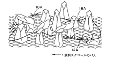
図2及び図3は、シューティングプログラム実行時の戦闘シーンを例示する概念図である。図2は、動かない敵キャラクタとの戦闘シーンであり、図3は、動く敵キャラクタ14Aとの戦闘シーンである。図3に示す戦闘シーンでは、フィールド上にパス16Aが設定されており、このパス上をドラゴンと敵キャラクタとが強制スクロールによって移動する。
2 and 3 are conceptual diagrams illustrating battle scenes during execution of the shooting program. FIG. 2 is a battle scene with an enemy character that does not move, and FIG. 3 is a battle scene with a moving
図2ではパスはなく、強制スクロールはされることがない一方で、ドラゴンは敵キャラクタの回りを自由に飛行することができる。この戦闘シーンのプログラム実行時では、敵キャラクタとプレイヤキャラクタとの間の戦闘の場合、所定の早さで時間が流れている状態で戦闘の終了まで継続される。 In FIG. 2, there is no pass and no forced scrolling, while the dragon can fly freely around the enemy character. When the battle scene program is executed, in the case of a battle between the enemy character and the player character, the game is continued until the battle is finished in a state where time passes at a predetermined speed.
移動マップ上を移動中に、イベント発生、例えば敵キャラクタに遭遇によってエンカウントフラグが立ち、或いはランダムフラグを立てて戦闘シーンに移行する。このいずれの戦闘シーンでも、既述のようにリアルタイムのシューティングが可能となる。図3の戦闘シーンでは後述するように、複数の敵キャラクタとドラゴンとの位置取りをシミュレートした遊戯が可能となる。 While moving on the movement map, an encounter flag is set when an event occurs, for example, an enemy character is encountered, or a random flag is set and a battle scene is entered. In any of these battle scenes, real-time shooting is possible as described above. In the battle scene of FIG. 3, as will be described later, a game simulating the positioning of a plurality of enemy characters and a dragon is possible.
ここで、位置とりとは、ドラゴンが敵の攻撃方向を予測して予め安全な位置に待避しておく、或いは敵キャラクタがドラゴンを追跡するなど、敵キャラクタ或いはドラゴンが自己によって戦闘上有利な位置を取らんとする行為である。 Here, positioning refers to a position where the enemy character or the dragon is advantageous in combat by himself, such as the dragon predicting the attack direction of the enemy and retreating to a safe position in advance, or the enemy character tracking the dragon. It is an act to try.
既述のように、移動マップから戦闘シーンへの移行は、エンカウント情報が発生した時に開始される。エンカウントフラグに「1」が設定されたとき、このエンカウント情報が発生したこととする。 As described above, the transition from the movement map to the battle scene is started when encounter information is generated. It is assumed that the encounter information is generated when “1” is set in the encounter flag.
図4は、移動マップ処理と戦闘シーン処理との関係を示すフローチャートであり、後述のハード構成を持つテレビゲーム機のCPUによって実行される。先ず、ゲームが開始すると、S4.0においてロールプレイングゲームの一場面としての図1記載の移動シーンが実行される。 FIG. 4 is a flowchart showing the relationship between the movement map process and the battle scene process, and is executed by the CPU of a video game machine having a hardware configuration to be described later. First, when the game is started, a moving scene shown in FIG. 1 as a scene of the role playing game is executed in S4.0.
S4.2では、戦闘シーンに移行するためのエンカウントフラグがチェックされ、エンカウントフラグが「1=エンカウントあり」の場合は次の戦闘シーンの処理へ移行する。エンカウントフラグが「0=エンカウントなし」の場合はS4.0に戻る。 In S4.2, the encounter flag for shifting to the battle scene is checked. If the encounter flag is “1 = There is an encounter”, the process proceeds to the next battle scene. If the encounter flag is “0 = no encounter”, the process returns to S4.0.
エンカウントフラグが立った場合は、ある特定の現象が生じた時のイベントエンカウントか或いはランダムに生じるランダムエンカウントかに応じて戦闘シーンに移行し、それぞれの戦闘シーンで処理の戦闘行動が実現される。これらの戦闘シーンは同じであっても、それぞれ異なるようにしても良い。 When the Encounter flag is set, the system shifts to the battle scene according to the event encounter when a specific phenomenon occurs or the random encounter that occurs at random, and the battle action of processing is realized in each battle scene Is done. These battle scenes may be the same or different.
イベントエンカウントの時の戦闘シーン(S4.6)は、既述のように図1に示すドラゴン10Aが飛行ルート上の敵キャラクタに遭遇したとき等特定のイベント発生時に発生する。なお、移動マップ上で敵キャラクタを表示するとき、プレイヤキャラクタは敵キャラクタと遭遇することを避けるように、遊戯者はドラゴンの飛行方向を制御することができる。 The battle scene (S4.6) at the event encounter occurs when a specific event occurs, such as when the dragon 10A shown in FIG. 1 encounters an enemy character on the flight route as described above. When the enemy character is displayed on the movement map, the player can control the flying direction of the dragon so that the player character avoids encountering the enemy character.
一方、ランダムエンカウントの戦闘シーン(S4.8)は、所定時間の経過やゲームの得点が特定の値に到った時等所定の条件が成立或いは発生した時に現れる。S4.10では、戦闘シーンが終了したか否かが判定され、その判定が肯定されると移動シーンへリターンし、それが否定されると戦闘行動にリターンする。 On the other hand, the battle scene of random encounter (S4.8) appears when a predetermined condition is satisfied or occurs, such as when a predetermined time elapses or when a game score reaches a specific value. In S4.10, it is determined whether or not the battle scene has ended. If the determination is affirmed, the process returns to the moving scene, and if the determination is negative, the process returns to the battle action.
イベント戦闘時やランダム戦闘時には、プレイヤキャラクタと敵キャラクタとの間で攻撃を仕掛けたり攻撃を避けたりする等のリアルタイムのシューティングゲームが再現される。 In event battle or random battle, a real-time shooting game such as making an attack or avoiding an attack between a player character and an enemy character is reproduced.
戦闘シーンの終了は、敵キャラクタの全消滅、プレイヤキャラクタの消滅、強制終了のとき等に肯定される。敵キャラクタやプレイヤキャラクタの消滅は、公知の手法によって検討される。すなわち、例えば、敵キャラクタを形成するポリゴンと仮想の武器のポリゴンとの衝突(コリジョン)を判定し、衝突が肯定されたとき敵キャラクタやプレイヤキャラクタの形状や状態値に変更が生じたり、その消滅が必要と判断される。この判断は、衝突により体力値が減少することにより、可能となる。 The end of the battle scene is affirmed when the enemy character is completely extinguished, the player character is extinguished or forcibly terminated. The disappearance of enemy characters and player characters is examined by a known method. That is, for example, a collision between a polygon forming an enemy character and a virtual weapon polygon is determined, and when the collision is affirmed, the shape or state value of the enemy character or player character changes or disappears. Is deemed necessary. This determination is made possible by the decrease in the physical strength value due to the collision.
この処理はゲームが終了するまで継続して実行される。図4に示す処理の中で、S4.0、S4.2はロールプレーイングゲームの処理ステップに相当し、S4.4以降の処理はシューティングゲームの処理ステップに相当する。 This process is continued until the game ends. In the processing shown in FIG. 4, S4.0 and S4.2 correspond to the role playing game processing steps, and the processing after S4.4 corresponds to the shooting game processing steps.
戦闘シーンは、既述のように図2のものと図3のものとから構成される。この実施例では、ロールプレイングゲームの処理ステップから他のゲーム画面、例えばシューティングの処理ステップに移行する際に、図3の場合、予め定められたパス(道筋)上をプレイヤキャラクタを強制的に飛行させることにより、シューティングの処理ステップに於けるシューティングの際にプレイヤキャラクタの移動方向制御が遊戯者にとって容易になる。 As described above, the battle scene is composed of those shown in FIG. 2 and FIG. In this embodiment, when moving from a role playing game processing step to another game screen, for example, a shooting processing step, in the case of FIG. 3, the player character is forced to fly on a predetermined path (path). This makes it easier for the player to control the movement direction of the player character during shooting in the shooting process step.
すなわち、シューティングの操作を遊戯者にとって優しくなるようにしている。図3の場合、パスの経路が適当に屈曲し、様々な背景(山、谷)を経るようにされているために、パスが単調にならないようにもしている。 That is, the shooting operation is made gentle for the player. In the case of FIG. 3, since the path of the path is appropriately bent and passes through various backgrounds (mountains and valleys), the path is also prevented from becoming monotonous.
このような決まったパスは仮想空間のワールド座標系に、特定点の座標ポイントを経るようにすることにより定義することが可能となる。 Such a fixed path can be defined by passing a coordinate point of a specific point in the world coordinate system of the virtual space.
次に、ゲーム装置のハードウエアの構造について説明する。図5は、その基本構成を示すものであって、ゲーム機の外観を示す斜視図に相当する。この図において、符号1は、TVゲーム機本体を示している。このTVゲーム機本体1の前面には、二つのコネクタ2a、2aが設けられており、これらのコネクタ2a、2aにはゲーム機操作用のPAD等のプリフェラル2b,2bがケーブル2c、2cを介して接続されている。
Next, the hardware structure of the game device will be described. FIG. 5 shows the basic configuration and corresponds to a perspective view showing the appearance of the game machine. In this figure,
また、TVゲーム機本体1の上部には、ROMカートリッジ接続用のカートリッジインターフェース(カートリッジI/F)1aが設けられている。同様に、TVゲーム機本体1の上部には、CD−ROM読取り用のCD−ROMドライブ1bが設けられている。TVゲーム機本体1の背面には、図示しないが、ビデオ出力端子及びオーディオ出力端子が設けられている。このビデオ出力端子はケーブル4aを介してTV受像機5のビデオ入力端子に接続されている。
Further, a cartridge interface (cartridge I / F) 1 a for connecting a ROM cartridge is provided on the upper part of the TV game machine
このオーディオ出力端子はケーブル4bを介してTV受像機5のオーディオ入力端子に接続されている。このようなゲーム機において、ユーザーがペリフェラル2b、2bを操作することにより、TV受像機5に映し出された画面を見ながらプレイヤキャラクタであるドラゴン10Aを操作してゲームを行うことができる。
This audio output terminal is connected to the audio input terminal of the
図6はこのゲーム装置のハードウアの機能ブロック図を示すものである。ゲーム機本体は、装置全体の制御を行うCPUブロック10、ゲーム画面の表示制御を行うビデオブロック11、効果音響等を生成するサウンドブロック12、CD─ROMの読出しを行うサブシステム13等により構成されている。
FIG. 6 shows a functional block diagram of the hardware of this game apparatus. The game machine body is composed of a
CPUブロック10は、SCU(System Control Unit )100、メインCPU101、RAM102、ROM103、カートリッジI/F1a、サブCPU104、CPUバス105等より構成されている。
The
メインCPU101は、装置全体の制御を行うものである。このメインCPU101は、内部にDSP(Digital Signal Processor)と同様な演算機能を備え、アプリケーションソフトを高速に実行可能になっている。
The
RAM102は、メインCPU101のワークエリアとして使用されるものである。ROM103は、初期化処理用のイニシャルプログラム等が書き込まれている。SCU100は、バス105、106、107を制御することにより、メインCPU101、VDP120、130、DSP140などの相互間のデータ入出力を円滑に行う。
The
また、SCU100は、内部にDMAコントローラを備え、ゲーム中のキャラクタデータ(ポリゴンデータ)をビデオブロック11内のVRAM121に転送することができる。これにより、ゲーム機等のアプリケーションソフトを高速に実行することができる。カートリッジI/F1aは、ROMカートリッジの形態で供給されるアプリケーションソフトをTVゲーム機本体内の所定のブロックに入力するためのものである。
Further, the
サブCPU104は、SMPC(System Manager & Peripheral Control )と呼ばれるもので、メインCPU101からの要求に応じて、ペリフェラル2b、2bからペリフェラルデータを図5のコネクタ2a、2aを介して収集する機能等を備えている。
The
メインCPU101は、サブCPU104から受け取ったペリフェラルデータに基づき、例えば仮想空間上(3次元空間)のキャラクタの(座標等の)回転変換や透視変換などの画像制御を行ってこれを画面に表示するための処理を行う。コネクタ2a、2aには、パッド、ジョイスティック、キーボード等のうち任意のペリフェラルを接続できる。サブCPU104は、コネクタ2a、2aに接続されたペリフェラルの種類を自動的に認識し、プロファイルの種類に応じた通信法規に従いペリフェラルデータ等を収集する機能を備えている。
Based on the peripheral data received from the
ビデオブロック11は、TVゲームのポリゴンデータからなるキャラクタ及び背景像に上書きするポリゴン画面の描画を行う第1のVPD(Video DisplayProcessor)120と、スクロール背景画面の描画、プライオリティ(表示優先順位)に基づくポリゴン画像データとスクロール画像データとの画面合成、クリッピングなどを行う第2のVDP130とを備えている。
The video block 11 is based on a first VPD (Video Display Processor) 120 that draws a polygon screen that overwrites a character and background image composed of polygon data of a TV game, and a scroll background screen drawing and priority (display priority). A
第1のVPD120はシステムレジスタ120aを内蔵するとともに、VRAM(DRAM)121及び2面のフレームバッファ122、123に接続されている。TVゲームのキャラクタを表すポリゴンの描画データは、メインCPU101を介して第1のVDP120に送られ、VRAM121に書き込まれた描画データは、例えば16または8ビット/pixel の形で描画用のフレームバッファ122(又は123)に描画される。描画されたフレームバッファ122(又は123)のデータは、表示モード時に第2のVDP130に送られる。
The
このようにフレームバッファには、バッファ122、123が使われており、描画と表示がフレーム毎に切り換わるダブルバッファ構造をなしている。さらに、描画を制御する情報は、メインCPU101からSCU100を介して第1のVPD120のシステムレジスタ120aに設定された指示に従って第1のVPD120が描画と表示を制御する。
As described above, the
一方、第2のVDP130は、レジスタ130a及びカラーRAM130bを内蔵するとともに、VRAM131に接続されている。また第2のVDP130はバス107を介して第1のVPD120及びSCU100に接続されるとともに、メモリ132及びエンコーダ160を介してビデオ出力端子Voに接続されている。ビデオ出力端子Voには、ケーブル4aを介してTV受像機5のビデオ入力端子が接続されている。
On the other hand, the
この第2のVDP130に対して、スクロール画面データはメインCPU101からSCU100を介してVRAM131及びカラーRAM130bに定義される。画像表示を制御する情報も同様にして第2のVDP130に定義される。VRAM131に定義されたデータは、第2のVDP130によりレジスタ130aに設定されている内容に従って読み出され、キャラクタに対する背景を表す各スクロール画面の画像データになる。各スクロール画面の画像データと第1のVPD120から送られてきたテクスチャマッピングが施されたポリゴンデータの画像データは、レジスタ130aにおける設定に従って表示優先順位(プライオリティ)が決められ、最終的な表示画面データに合成される。
For the
この表示画像データがパレット形式の場合、第2のVDP130によって、その値に従ってカラーRAM130bに定義されているカラーデータが読み出され、表示カラーデータが生成される。また、表示画像データがRGB形式の場合、表示画像データがそのまま表示カラーデータとなる。この表示カラーデータは、メモリ132に蓄えられた後にエンコーダ160に出力される。エンコーダ160は、この画像データに同期信号等を付加することにより映像信号を生成し、ビデオ出力端子Voを介してTV受像機5のビデオ入力端子に供給する。これにより、TV受像機5のスクリーンにゲーム画面が表示される。
When the display image data is in the palette format, the
サウンドブロック12は、PCM方式あるいはFM方式に従い音声合成を行うDSP140と、このDSP140の制御等を行うCPU141とを備えている。DSP140により生成された音声データは、D/Aコンバータ170により2チャンネルの音声信号に変換された後に、インターフェース171を介してオーディオ出力端子Aoに供給される。
The sound block 12 includes a DSP 140 that performs speech synthesis in accordance with the PCM method or the FM method, and a
このオーディオ出力端子Aoは、ケーブル4bを介してTV受像機5のオーディオ入力端子に接続されている。このため、音響信号は、オーディオ出力端子Ao、ケーブル4bを介してTV受像機5のオーディオ入力端子からオーディオ増幅回路(図示せず)に入力される。オーディオ増幅回路で増幅された音声信号は、TV受像機5に内蔵されているスピーカ5a、5bを駆動する。
The audio output terminal Ao is connected to the audio input terminal of the
サブシステム13は、CD−ROMドライブ1b、CD−I/F180、CPU181、MPEG−AUDIO部182、MPEG−VIDEO部183等により構成されている。このサブシステム13は、CD−ROMの形態で供給されるアプリケーションソフトの読み込み、動画の再生等を行う機能を備えている。CD−ROMドライブ1bは、CD−ROMからデータを読み取るものである。CPU181は、CD−ROMドライブ1bの制御、読み取られたデータの誤り訂正等の処理を行うものである。CD−ROMから読み取られたデータは、CD−I/F180、バス106、SCU100を介してメインCPU101に供給され、アプリケーションソフトとして利用される。
The subsystem 13 includes a CD-ROM drive 1b, a CD-I /
また、MPEG−AUDIO部182、MPEG−VIDEO部183は、MPEG規格(Motion Picture Expert Group)により圧縮されたデータを復元する装置である。これらのMPEG−AUDIO部182、MPEG−VIDEO部183を用いてCD−ROMに書き込まれたMPEG圧縮データの復元を行うことにより、動画の再生を行うことが可能となる。
The MPEG-
ここで説明したゲーム機はシューティングゲームを遊戯者にとって操作が優しく、しかもゲームの面白みを損なわないような処理でシミュレートするように構成されている。以下、このゲーム機の各種動作について説明する。 The game machine described here is configured to simulate a shooting game by a process that is easy for a player to operate and does not impair the fun of the game. Hereinafter, various operations of the game machine will be described.
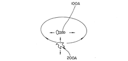
先ず、図7は、図3に示す戦闘シーンで実行される一処理に相当するものである。図7には、敵キャラクタ100Aとプレイヤキャラクタ200Aとの空間的な関係が模式的に示されている。
First, FIG. 7 corresponds to one process executed in the battle scene shown in FIG. FIG. 7 schematically shows a spatial relationship between the
プレイヤキャラクタ200Aは、既述のように空飛ぶドラゴンを模擬したものであり、敵キャラクタ100Aは例えば空とぶ巨大昆虫を模擬したものである。図8はプレイヤキャラクタ及び敵キャラクタの位置関係を斜視図として示している。なお、プレイヤキャラクタ或いは敵キャラクタに相当するキャラクタはどのような形態のものであっても良い。敵キャラクタは1体でも、或いは複数体であっても良い。
The
プレイヤキャラクタは敵キャラクタの回りを矢印方向に回るとともに、上下にも矢印のように移動することができる。敵キャラクタは図3に示すパスに沿って矢印のように仮想空間内を移動する。プレイヤキャラクタは敵キャラクタの移動に合わせて敵キャラクタの回りを上下に移動しながら回ることができる。 The player character can move around the enemy character in the direction of the arrow and move up and down as indicated by the arrow. The enemy character moves in the virtual space as indicated by an arrow along the path shown in FIG. The player character can turn while moving up and down around the enemy character as the enemy character moves.
すなわち、図8はプレイヤキャラクタの移動範囲を具体的に示したものであり、敵キャラクタの回りに設定された特定形状の空間域としてのシリンダ形状(円筒)様の領域(移動エリア)202の表面をプレイヤキャラクタが移動できることを示している。なお、敵キャラクタがプレイヤキャラクタの周りを周回するようなものでも良い。また、戦闘シーンの際、図3の場合とは異なるように、敵キャラクタが仮想空間内を自由な方向に移動しても良い。 That is, FIG. 8 specifically shows the moving range of the player character, and the surface of a cylinder-shaped (cylindrical) -like area (moving area) 202 as a space area of a specific shape set around the enemy character. Indicates that the player character can move. Note that the enemy character may circulate around the player character. Further, during the battle scene, the enemy character may move in the virtual space in a free direction, unlike the case of FIG.
敵キャラクタは、プレイヤキャラクタに対して多種類の攻撃をランダム、又は所定のパターンや敵固有の攻撃方法で仕掛け、遊戯者はプレイヤキャラクタを自由に操作して(敵キャラクタを予測してプレイヤキャラクタをエリア内で操作して)、敵キャラクタからの攻撃を避けつつ敵キャラクタに攻撃を加える。 The enemy character makes a variety of attacks against the player character at random or with a predetermined pattern or an enemy-specific attack method, and the player freely operates the player character (predicts the enemy character and determines the player character Operate in the area) and attack the enemy character while avoiding attacks from the enemy character.
プレイヤキャラクタが所定の時間以内に敵キャラクタに致命量のダメージを与えればゲームに勝利し、プレイヤキャラクタが致命量のダメージを受けた場合にゲーム終了となる。 If the player character gives a fatal amount of damage to the enemy character within a predetermined time, the game is won, and if the player character receives the fatal amount of damage, the game ends.
このような領域202を設けることにより、次のような利点がある。プレイヤキャラクタの行動範囲をこの領域に限ることにより、敵キャラクタの周囲近傍にプレイヤキャラクタを敵キャラクタに臨むように容易に配置させることができ、遊戯者がプレイヤキャラクタを敵キャラクタに対して有利な位置にマッピングするようにできる。
Providing such a
図34はここに示すプレイヤキャラクタの配置を制御するプログラムに基づくフローチャートであり、図3の戦闘シーンがスタートすると戦闘シーンが終わるまでCPUによって繰り返し実行される。 FIG. 34 is a flowchart based on the program for controlling the arrangement of the player characters shown here. When the battle scene of FIG. 3 starts, it is repeatedly executed by the CPU until the battle scene ends.
S34.0において、敵キャラクタのパス上の位置が検出され、S34.2においてシリンダ様形状の決定を行う。S34.2ではシリンダの直径や高さを決定し、S34.4においてそのシリンダの中心に敵キャラクタが来るように、すなわち、敵キャラクタの中心にこのシリンダを形成して敵キャラクタとともにパス上を移動させる。Sではこのシリンダの表面にドラゴンを配置する。したがって、ドラゴンも敵キャラクタとともにパスに沿って移動する。 In S34.0, the position of the enemy character on the path is detected, and the cylinder-like shape is determined in S34.2. In S34.2, the diameter and height of the cylinder are determined, and in S34.4, the enemy character comes to the center of the cylinder, that is, this cylinder is formed at the center of the enemy character and moves along the path with the enemy character. Let In S, a dragon is placed on the surface of this cylinder. Therefore, the dragon moves along with the enemy character along the path.
S34.2におけるシリンダの直径や高さの決定は、次のようにして例えば実行される。図9に示すように、敵キャラクタ100Aが大きな形態(ポリゴン)となった際にシリンダ様領域202の径を大きくする。このために、CPUは、例えば、仮想空間内での敵キャラクタを構成するポリゴンの頂点座標を読み込み、XYZの各方向の最大座標と最小座標の差から敵キャラクタの大きさを決定する。もっとも、敵キャラクタ毎にシリンダの形態を決めてテーブルにしておくようにしても良い。
The determination of the diameter and height of the cylinder in S34.2 is performed as follows, for example. As shown in FIG. 9, the diameter of the cylinder-
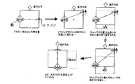
遊戯者は、ゲーム機の方向キー2bbを所定方向に操作することによって、プレイヤキャラクタをシリンダ様領域表面の前後左右側に連続的に移動させることができる。しかし、プレイヤキャラクタの移動範囲をシリンダ領域の表面に限ったとしても、時としてプレイヤにとってドラゴンをシリンダ様領域の臨む側(前後左右のどれか)に移動させることが困難な場合もありうるから、シリンダを図8に示す4つのブロックエリア(前後左右)に分割し、一つのエリアから他のエリアへの移動際、移動先のエリアの特定位置、例えばエリアの中心に強制的に移動されるようにしても良い。すなわち、図35はこのことを示すものであり、シリンダ202の或ブロックから他のブロックに向けてドラゴンが移動するとき、特定点350から特定点352にドラゴンが強制的に移動されることを示している。この場合、特定点に到った後のドラゴンはこのブロック内において、ブロック表面の上下左右に移動しても良いし、或いは移動できないようにしても良い。
The player can move the player character continuously to the front, rear, left and right sides of the surface of the cylinder-like region by operating the direction key 2bb of the game machine in a predetermined direction. However, even if the movement range of the player character is limited to the surface of the cylinder area, sometimes it may be difficult for the player to move the dragon to the side facing the cylinder-like area (either forward, backward, left, or right) The cylinder is divided into four block areas (front, rear, left and right) shown in FIG. 8, and when moving from one area to another area, the cylinder is forcibly moved to a specific position of the destination area, for example, the center of the area. Anyway. That is, FIG. 35 shows this, and shows that when the dragon moves from one block of the
ブロック間のドラゴンの移動は例えば次のとおりである。方向キーの操作方向に対応させて、方向キーの上方向キーの操作時には、シリンダの進行方向の前面のブロックにドラゴンを移動させ、したキーの場合には後面のブロックに移動させ、右キー操作の場合には右ブロックに移動させ、左キー操作の場合には左ブロックに移動させる。また、上下キーをシリンダ側面でのドラゴンの高度制御用にし、左右キーをシリンダの側面方向の移動制御用にしても良い。なお、ドランゴンはシリンダ形状の表面ばかりでなく、その内側でも移動できるようにしても良い。 The movement of the dragon between blocks is as follows, for example. Corresponding to the operation direction of the direction key, when operating the up direction key of the direction key, move the dragon to the front block in the traveling direction of the cylinder, and in the case of the key, move it to the back block and operate the right key In the case of, move to the right block, and in the case of left key operation, move to the left block. Further, the up / down keys may be used for dragon's altitude control on the cylinder side surface, and the left / right keys may be used for movement control in the cylinder side surface direction. The drangon may be moved not only on the cylinder-shaped surface but also on the inside thereof.
この4つのブロックエリアは、シンリダ様領域202を互いに直交する二つの直方面(500,502)によって分割されたものとして定義される。なお、この直方面は、領域202の分割の仕方を示すためのものであり、実際にこのような直方面を設けることまでは行われない。
These four block areas are defined as those obtained by dividing the cylinder-
メインCPUは、媒体としてのカートリッジI/F又はCDROMから供給されるアプリケーションソフトウエアによって、図7及び図8の敵キャラクタ100Aからプレイヤキャラクタ200Aに向けて弾丸を発射し、プレイヤキャラクタがこの弾丸を被った場合には、プレイヤキャラクタが破壊されたり、プレイヤキャラクタを消滅されたりする映像を作成する。プレイヤキャラクタがこの弾丸を被らなかった場合には、勿論プレイヤキャラクタにダメージを与えるような映像は生じない。
The main CPU fires a bullet from the
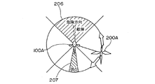
図10はこの時の映像の模式図である。図10は、図8の平面図に相当するものである。敵キャラクタ100Aからの弾丸発射は前後左右の4つのブロック毎(図8のブロックA1乃至A4のいずれか)に分けて行われる。
FIG. 10 is a schematic diagram of the video at this time. FIG. 10 corresponds to the plan view of FIG. Bullet firing from the
図10は、前側のブロック206に弾丸を発射している状態を示している。プレイヤキャラクタ202Aがこのブロック内に居ると被弾の可能性が高くなる。一方、プレイヤキャラクタが右側のブロックに居れば、被弾の可能性はない。敵キャラクタには仮想的に弱点領域(弱点コリジョン)207があり、この領域に攻撃するために、プレイヤキャラクタを敵キャラクタに対する後ろ側のブロックに回り込ませることが効果的である。
FIG. 10 shows a state in which a bullet is fired at the
既述のように敵キャラクタからの弾丸の射出方向は、4つのブロック毎に設定されている。すなわち、弾丸は方向を持ち、又弾丸はある規則に支配されている。したがって、遊戯者は弾丸が飛ぶ方向を予測して、これに備えることができる。 As described above, the bullet emission direction from the enemy character is set for every four blocks. That is, bullets have direction, and bullets are subject to certain rules. Therefore, the player can prepare for this by predicting the direction in which the bullets will fly.
弾丸としては、光線弾、誘導弾等適宜種々のものがある。これら弾丸の種類、コースをCPUがプログラムに応じて決定する。このように、弾丸の移動形態には、方向や種類の点において複数存在する。 There are various bullets as appropriate, such as light bullets and guided bullets. The CPU determines the type and course of these bullets according to the program. Thus, there are a plurality of bullet movement forms in terms of direction and type.
プレイヤキャラクタは敵キャラクタからの弾丸が命中することを避けるために、そして、敵キャラクタの弱点を効果的に攻撃するために、4つのブロック毎のいずれかに配置される。 The player character is placed in any one of the four blocks in order to avoid hitting bullets from the enemy character and to effectively attack the weak points of the enemy character.
弾丸の方向や、発射される弾丸の種類、弾丸の発射タイミング、時間等に規則を設けることにより、遊戯者はこの規則を理解し弾丸の移動形態を予想して、この弾丸を避けるように、例えば、プレイヤキャラクタを敵弾が及ばないエリアを選択して予め待避させることができる。 By setting rules on the direction of bullets, the type of bullets to be fired, the timing of bullets firing, time, etc., players understand this rule, anticipate the movement of the bullet, and avoid this bullet, For example, the player character can be saved in advance by selecting an area where the enemy bullet does not reach.
遊戯者にプレイヤキャラクタの敵キャラクタに対する位置を明示する目的で、図11に示す戦闘画面には仮想レーダ11Aが表示される。この仮想レーダには、プレイヤキャラクタ200Aのシンボルと敵キャラクタ100Aのシンボルが表示される。したがって、この仮想レーダにより、敵キャラクタとプレイヤキャラクタとの相対的位置関係が分かる。
For the purpose of clearly showing the position of the player character relative to the enemy character to the player, a virtual radar 11A is displayed on the battle screen shown in FIG. On this virtual radar, the symbol of the
図11は、プレイヤキャラクタ200Aが敵キャラクタ100Aの前のブロックに配置されている状態を示している。プレイヤキャラクタが存在するブロックの領域の色彩を背景画とは異なるようにして、遊戯者に一見してプレイヤキャラクタが敵キャラクタに対して成すブロック位置分かるようにできる。
FIG. 11 shows a state in which the
遊戯者がプレイヤキャラクタの移動エリアとしていずれかのものを図8のA1乃至A4から選択することにより、後述のフローチャートに示されるように、プレイヤキャラクタがこの移動エリアに自動的に移動される。 When the player selects one of the movement areas of the player character from A1 to A4 in FIG. 8, the player character is automatically moved to this movement area as shown in the flowchart described later.
なお、図11において、110はドラゴンから敵キャラクタへ攻撃可能状態になったことを、遊戯者に示すためのゲージであり、このゲージが最大値に達することによって遊戯者はドラゴンから敵キャラクタに対して所望の武器によって攻撃を仕掛けることができる。この武器ゲージに対して、本願発明は特徴的処理を提供している。このことは後述する。 In FIG. 11, 110 is a gauge for indicating to the player that the dragon is able to attack the enemy character. When this gauge reaches the maximum value, the player can attack the enemy character from the dragon. To attack with the desired weapon. The present invention provides a characteristic process for this weapon gauge. This will be described later.
また、敵キャラクタ100Aの上にある数値「10」は、敵キャラクタのダメージを表すものである。HPはヒットポイントと呼ばれるものであり、プレイヤキャラクタの残存寿命が分母に対する分子の数値として表現されている。分子が現在の残りHPであり、分母が最大HPである。また、BPとはバーサークポイントと呼ばれるものであり、プレイヤキャラクタから敵キャラクタに対して技を繰り出す余力容量を示すポイントである。技とは、例えば、プログラム上の魔法に当たるもの、或いは必殺技に当たるものである。
The numerical value “10” above the
弾丸の移動形態には、弾丸が前後左右の順番に発射される、或いは敵キャラクタの特定の動作(振動や変動)や形態の変化(大きさ、形、色)のタイミングによって発射される等の複数の形態が存在する。ここで、弾丸は請求項記載の移動する移動キャラクタに相当する。 As for the movement form of bullets, bullets are fired in the order of front, back, left, and right, or fired at the timing of specific movement (vibration or fluctuation) of the enemy character or change of form (size, shape, color), etc. There are several forms. Here, the bullet corresponds to the moving character described in the claims.
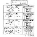
図12は、前記CPU101によって攻撃の予測処理を達成するためのフローチャートを示す。このフローチャートは、大きくは、プレイヤキャラクタの移動エリアを選択し、敵キャラクタに対する攻撃武器の選択を行うフェーズF1と、プレイヤキャラクタと敵キャラクタとの間の攻撃の成否を実行するフェーズF2とから構成されている。これらのフェーズは1インターラプト毎に繰り返し実行される。
FIG. 12 is a flowchart for achieving the attack prediction process by the
遊戯者により移動エリアの選択結果がコントローラ2bを介してゲーム機に入力される(S600)。この選択は遊戯者が敵弾の発射方向や発射タイミング、或いは敵キャラクタの弱点方向を予想して行われる。この入力結果に応じて、CPUはプレイヤキャラクタを選択されたブロックに配置する。
The selection result of the moving area is input to the game machine by the player via the
次に、S602で、遊戯者により武器選択が行われる。選択武器の種類によって、敵キャラクタに向けて表示される照準カーソルを後述のように画面に表示する。選択武器の種類に応じてカーソルの形態を変えることが出来る。 Next, in S602, weapon selection is performed by the player. An aiming cursor displayed toward the enemy character is displayed on the screen as described later depending on the type of the selected weapon. The cursor shape can be changed according to the type of weapon selected.
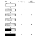
例えば、後に図18に図示されるように、選択した武器の種類/威力に合わせて、表示される照準カーソルの形状や大きさを変化させたり、照準に近いほど威力が高いことを示すために、カーソルを大型矩形(1)、小型矩形(2)、大型円形(3)、矩形多重枠(4)、円形多重枠(5)等に変えることが出来る。この照準内に、敵キャラクタを入れてトリガーをオンすることにより敵キャラクタへの攻撃を成功させる。トリガーは前記コントロータ2b内の所定ボタンによって構成される。
For example, as shown in FIG. 18 later, in order to change the shape and size of the displayed aiming cursor in accordance with the type / power of the selected weapon, or to indicate that the closer the aiming is, the higher the power is The cursor can be changed to a large rectangle (1), a small rectangle (2), a large circle (3), a rectangular multiple frame (4), a circular multiple frame (5), or the like. The enemy character is successfully attacked by putting the enemy character in the aim and turning on the trigger. The trigger is constituted by a predetermined button in the
S604では、移動エリアの選択結果に応じてプレイヤキャラクタを選択された図8のエリアの内の一つにマッピングし、選択武器の種類に応じ照準を表示し、また、敵キャラクタから弾丸が発射される映像が形成される。 In S604, the player character is mapped to one of the selected areas in FIG. 8 according to the selection result of the moving area, the aim is displayed according to the type of the selected weapon, and a bullet is fired from the enemy character. Video is formed.
このとき、弾丸の発射コースや弾丸の種類等の弾丸の移動形態は、アプリケーションソフトウエアにより、CPU101によって種々或るものの中から特定のものが決定される。選択された移動エリアにプレイヤキャラクタを移動させることは、CPU101によって自動的に行われるようにしても良い。また、遊戯者はコントローラ2bの方向キー2bbによって自身によりプレイヤキャラクタを移動エリアに移動させても良い。
At this time, the bullet movement course and the bullet movement type such as the bullet type are determined by the
次いで、ステップ606において、この予測が結果的に正しかったか、或いは誤ったかが判定される。すなわち、同ステップにおいて、予測が正しければ、弾丸とプレイヤキャラクタとの当たり判定(仮想空間における座標の重なりの判定)が当たりなしと判定され、予測が誤っていれば当たりありと判定される。 Then, in step 606, it is determined whether the prediction was consequently correct or incorrect. That is, in this step, if the prediction is correct, it is determined that the hit determination between the bullet and the player character (determination of overlapping coordinates in the virtual space) is not successful, and if the prediction is incorrect, it is determined that the hit is correct.
予測誤りの場合には、S608に移行してプレイヤキャラクタへのダメージ量が積算され、プレイヤキャラクタのダメージが所定以上になった場合にプレイヤキャラクタを消滅させて新たなプレイヤキャラクタを出現させ(S610,S612)、ダメージが所定値未満である場合にはS614に移行する。 In the case of a prediction error, the process proceeds to S608, where the amount of damage to the player character is integrated, and when the damage of the player character exceeds a predetermined value, the player character disappears and a new player character appears (S610, S612) If the damage is less than the predetermined value, the process proceeds to S614.
S614は、S606に於ける予測結果が正しい場合にも採られるステップである。S614では、当たり判定の手法により、プレイヤキャラクタから敵キャラクタへの射撃が成功したか否かが判定される。これが肯定されると敵キャラクタへのダメージ追加処理を行い、敵キャラクタの損傷や敵キャラクタの消滅、新規な敵キャラクタの出現等の処理が実行される(S616)。 S614 is a step taken even when the prediction result in S606 is correct. In S614, it is determined by the hit determination method whether or not the shooting from the player character to the enemy character is successful. If this is affirmed, damage addition processing is performed on the enemy character, and processing such as damage to the enemy character, disappearance of the enemy character, appearance of a new enemy character, and the like is executed (S616).
一方、これが否定されると、このステップをスキップしてリターンする。S610においてプレイヤキャラクタのダメージ判定が所定値未満であるとS614に移行する。 On the other hand, if this is denied, this step is skipped and the process returns. If the damage determination of the player character is less than the predetermined value in S610, the process proceeds to S614.
請求項に記載の移動手段はS604によって実現され、決定手段はS604によって実現され、予測手段はS600によって実現され、キャラクタ位置設定手段はS604によって実現され、表示処理制御手段は、S606以降によって実現される。 The moving means described in the claims is realized by S604, the determining means is realized by S604, the predicting means is realized by S600, the character position setting means is realized by S604, and the display processing control means is realized by S606 and thereafter. The
なお、この実施形態では敵キャラクタの弾丸発射がゲーム装置側のCPUによって制御される例について説明したが、対戦相手としての他の遊戯者によってコントローラ2bを介して制御されるものであっても良い。この時は、弾丸の移動形態が対戦者の意志によりランダムに選択されることがあり、遊戯者はこの対戦者の意志をいわば予想して、プレイヤキャラクタの移動先を制御することになる。
In addition, although this embodiment demonstrated the example by which the bullet launch of an enemy character is controlled by CPU of the game device side, it may be controlled via the
この実施形態に示されたゲーム装置によれば、遊戯者が敵キャラクタの弾丸発射形態を予想しこの予測結果をゲーム機に入力しさえすれば、プレイヤキャラクタが所定のコースに自動的に移動され、うまくすれば、弾丸を避けることができるので、3D空間内であってもキャラクタを弾を避けるため等にうまく、かつ簡単にコントロールすることができる。 According to the game device shown in this embodiment, the player character is automatically moved to a predetermined course as long as the player predicts the bullet firing mode of the enemy character and inputs the prediction result to the game machine. If done well, bullets can be avoided, so even in 3D space, the character can be controlled well and easily to avoid bullets.
なお、移動エリアの選択があるとブロックエリア毎の所定のフラグが立てられてRAMに一時記憶され、CPUはこのフラグを見てプレイヤキャラクタを該当するエリアにマッピングすることができる。また、遊戯者がプレイヤキャラクタをエリア内で上下左右に移動させることにより、敵キャラクタからプレイヤキャラクタに向けた弾を避けることができる。 When a moving area is selected, a predetermined flag for each block area is set and temporarily stored in the RAM, and the CPU can map the player character to the corresponding area by referring to this flag. Also, the player can avoid bullets from the enemy character toward the player character by moving the player character up, down, left and right within the area.
先に選択武器によって照準の形態を変えることを説明した。次に、敵キャラクタからの攻撃を防御するための、すなわち、敵弾を迎撃するための応戦弾を選択する場合について説明する。 I explained that the form of aiming is changed by the selected weapon. Next, a description will be given of the case of selecting a response bullet for preventing an attack from an enemy character, that is, for intercepting an enemy bullet.
図13は、これを示す模式図である。敵キャラクタ100Aの前面にプレイヤキャラクタ200Aが向き合って位置している。敵キャラクタから単一の弾丸210がプレイヤキャラクタに発射されている。(1)はこの状態の平面図であり、(2)は側面図である。この弾丸の軌跡は複数の形態を取り得る。
FIG. 13 is a schematic diagram showing this. The
プレイヤキャラクタに向かって、プレイヤキャラクタの上を狙った直線弾、下を狙った直線弾、上から下に向かった曲線弾、下から上に向かった曲線弾、左から右に曲がった曲線弾、右から左に曲がった曲線弾がある。 To the player character, a straight bullet aimed at the top of the player character, a straight bullet aimed at the bottom, a curved bullet directed from above to below, a curved bullet directed from below to above, a curved bullet curved from left to right, There is a curved bullet that turns from right to left.
プレイヤキャラクタは自身から応戦弾を発射して敵キャラクタからの弾丸がプレイヤキャラクタに命中しないようにプレイヤキャラクタの手前で破壊するようにする。この第2実施形態では、このようなゲーム画面がモニタの映像に表示される。 The player character fires a battle bullet from itself and destroys it before the player character so that bullets from the enemy character do not hit the player character. In the second embodiment, such a game screen is displayed on a monitor image.
遊戯者には、プレイヤキャラクタの先端にある仮想カメラの視点から敵キャラクタに臨む映像が表示される。図14は画面に表示される、プレイヤキャラクタの側にとっての応戦用のカーソル表示体を示したものである。このカーソルはC1とC2の2重表示になっている。 The player is presented with an image that faces the enemy character from the viewpoint of the virtual camera at the tip of the player character. FIG. 14 shows a cursor display for battle for the player character displayed on the screen. This cursor is a double display of C1 and C2.
遊戯者はこのカーソルを敵弾に合わせて移動させコントローラのトリガをオンすると、応戦弾がカーソルに向けて発射され、カーソル内に敵弾が有る場合で応戦弾の発射タイミングが適切であれば、敵弾が応戦弾によって破壊される映像がシミュレートされる。 When the player moves this cursor to the enemy bullet and turns on the trigger of the controller, the battle bullet is fired toward the cursor, and if there is an enemy bullet in the cursor and the firing timing of the battle bullet is appropriate, Simulates the image of an enemy bullet being destroyed by a response bullet.
敵弾がカーソル内に来ないとこの応戦が失敗と判定される。敵弾の移動は高速であるので、カーソルを敵弾に合わせて移動させることは通常困難である。敵弾のコースと敵弾の種類を予め予測してこの予測結果に応じてカーソルの位置を設定することがポイントである。このことは後述する。 If the enemy bullet does not come within the cursor, the response is determined to have failed. Since the movement of enemy bullets is fast, it is usually difficult to move the cursor along with the enemy bullets. The point is that the course of enemy bullets and the type of enemy bullets are predicted in advance, and the position of the cursor is set according to the prediction result. This will be described later.
なお、敵弾がC1のカーソルで示された範囲を通過するならば、敵弾の破壊が可能であり、特にC2のカーソルの範囲に入れば、より確実に敵弾の破壊が達成される。C2のカーソルはC1の中心にほぼ所定の大きさで表示される。なお、このカーソルも請求項のキャラクタの一つである。 It should be noted that if the enemy bullet passes through the range indicated by the C1 cursor, the enemy bullet can be destroyed. In particular, if the enemy bullet enters the C2 cursor range, the enemy bullet destruction can be achieved more reliably. The cursor C2 is displayed at a predetermined size in the center of C1. This cursor is also one of the claimed characters.
図15はカーソルの移動範囲を一点鎖線で示すものである。A1からA4は、カーソルの位置設定先を示す範囲である。A1は遊戯者から見て右上、A2は右下、A3は左上、A4は左下である。遊戯者は敵弾の通過位置(通過コース)を敵弾の発射以前に予測し、カーソルの移動先をA1からA4のいずれかに設定する。 FIG. 15 shows the movement range of the cursor by a one-dot chain line. A1 to A4 are ranges indicating the cursor position setting destination. A1 is the upper right as viewed from the player, A2 is the lower right, A3 is the upper left, and A4 is the lower left. The player predicts the passing position (passing course) of the enemy bullet before the enemy bullet is fired, and sets the movement destination of the cursor to any one of A1 to A4.
そして、その後、カーソルの位置を調整して敵弾をC2のカーソル内に合わせるようにする。仮に、この予想が正解であれば、敵弾を少なくともC1のカーソル内に含ませることは容易である。一方、この予想が外れた場合にはこれが困難である。予想が外れた場合、例えばA1の位置にあるカーソルをA4の位置まで移動させてカーソル内に敵弾を含ませることは移動量が大きく、高速で移動する敵弾にカーソルを追従させることは難しい。カーソル内に敵弾を含ませることができないと敵弾によりプレイヤキャラクタが損傷を受ける。 After that, the position of the cursor is adjusted so that the enemy bullet is aligned with the cursor of C2. If this prediction is correct, it is easy to include enemy bullets at least in the cursor of C1. On the other hand, if this expectation is lost, this is difficult. If the prediction is not met, for example, moving the cursor at the A1 position to the A4 position and including the enemy bullet in the cursor has a large amount of movement, and it is difficult to make the cursor follow the enemy bullet moving at high speed. . If an enemy bullet cannot be included in the cursor, the player character is damaged by the enemy bullet.
カーソルC2の存在の意義は次のとおりである。仮に、敵弾のコースが予想と当たっても、敵弾の種類が違うと敵弾がカーソルC1内を通過する程度が異なるとする。例えば、敵弾が直線弾であれば、カーソルC2内に敵弾が容易に含まれるが、曲線弾であるとC1内を通過するものの、C2内を通過しない確率が高くなる。よって、曲線弾の場合にはC2内を通過するようにカーソルを微調整して確実に敵弾を破壊することを遊戯者が競うことができる。もっとも、このカーソルC2を省くことは可能である。 The significance of the presence of the cursor C2 is as follows. Even if the course of the enemy bullet hits the prediction, the degree to which the enemy bullet passes through the cursor C1 is different if the enemy bullet type is different. For example, if an enemy bullet is a straight bullet, an enemy bullet is easily included in the cursor C2, but if it is a curved bullet, it passes through C1, but the probability that it does not pass through C2 increases. Therefore, in the case of a curved bullet, the player can compete to finely adjust the cursor so as to pass through C2 and reliably destroy the enemy bullet. However, it is possible to omit the cursor C2.
図16はカーソルC2の形態を示したものである。遊戯者が、直線弾か曲線弾か、曲線弾ではどのような曲線弾かを予測する。予測結果に応じてC2の中心カーソルの形態が設定される。(5)は直線弾の場合である。このものは上下左右うに均等な形態を持っている。勿論矩形の形態に変えて円形でも良い。C1も同じである。 FIG. 16 shows the form of the cursor C2. The player predicts whether it is a straight or curved bullet, or a curved bullet. The form of the C2 center cursor is set according to the prediction result. (5) is a case of a straight bullet. This one has an even shape on the top, bottom, left and right. Of course, it may be circular instead of rectangular. The same applies to C1.
(1)は遊戯者のから見て(仮想カメラから見て、仮想カメラは図7のプレイヤキャラクタの敵キャラクタ側の先端に設定されているものとする。)、下から上に向かって曲がる曲線弾に対応するためのカーソルC2である。(2)は上から下、(3)は左から右、(4)は右から左に曲がる曲線弾に対応させるためのものである。 (1) is a curve that curves from the bottom to the top as viewed from the player (as viewed from the virtual camera, the virtual camera is set at the tip of the player character in FIG. 7 on the enemy character side). A cursor C2 for responding to a bullet. (2) corresponds to curved bullets turning from top to bottom, (3) from left to right, and (4) from right to left.
曲がる方向に幅広のカーソルであれば、敵弾の曲がりに対する予想が当たった際、さらに敵弾をより効果的にカーソルC2内に含ませてこれを確実に破壊することができる。 If the cursor is wide in the direction of bending, it is possible to more effectively include the enemy bullet in the cursor C2 and reliably destroy the enemy bullet when it is predicted that the enemy bullet will be bent.
図17はカーソルと敵弾との重なり判定処理のフローチャートである。S1100において、敵弾の通過がカーソルC1内であるかが判定される。S1102において、さらに敵弾の通過がカーソルC2内であるかが判定される。S1104,S1106では応戦弾の発射タイミングが適切か否かが判定される。 FIG. 17 is a flowchart of an overlap determination process between a cursor and an enemy bullet. In S1100, it is determined whether the enemy bullet passes within the cursor C1. In S1102, it is further determined whether or not the enemy bullet passes within the cursor C2. In S1104 and S1106, it is determined whether or not the response timing of the response bullet is appropriate.
S1104で発射タイミングが適切な場合は、S1108で敵弾破壊の映像が作成される。この時の敵弾破壊確率は高い。S1106の判定が肯定された場合も同映像が作成される。 If the firing timing is appropriate in S1104, an image of enemy bullet destruction is created in S1108. The enemy destruction probability at this time is high. The same video is also created when the determination in S1106 is affirmed.
この時の敵弾破壊確率は、S1108よりも低い。S1104とS1106が否定の判定であれば、応戦失敗と判定されて敵弾は破壊されない(S1112)。遊戯者側からの応戦がない場合もS1104,S1106で「NO」と判定される。また、S1100で敵弾がC1通過しない場合も敵弾非破壊と判定される。 The enemy bullet destruction probability at this time is lower than S1108. If S1104 and S1106 are negative, it is determined that the battle has failed and the enemy bullet is not destroyed (S1112). When there is no response from the player side, “NO” is determined in S1104 and S1106. Also, if the enemy bullet does not pass C1 in S1100, it is determined that the enemy bullet is not destroyed.
この実施形態によっても敵弾の形態を予想し、この予想結果に応じて応戦用のカーソル(照準)を特定の位置に設定するので、実施形態1と同様な効果を達成することができる。また、図12のエリア選択/武器選択のフェーズF1の間では、敵弾の攻撃方向や敵弾の種類、特性が分からないので、エリア選択とは別に、或いはこれと合わせて移動する移動キャラクタとしての敵弾の特性を予想しこれに備えるという新たな観点のゲーム上の駆け引きを生じさせることができる。 Also in this embodiment, the form of the enemy bullet is predicted, and the battle cursor (aiming) is set at a specific position according to the predicted result, so that the same effect as in the first embodiment can be achieved. Further, during the area selection / weapon selection phase F1 in FIG. 12, since the attack direction of enemy bullets, the type and characteristics of enemy bullets are unknown, as a moving character that moves separately from or together with the area selection. It is possible to generate a game of bargaining in a new viewpoint that anticipates and prepares for the characteristics of enemy bullets.
また、既述の実施形態によれば、敵の攻撃を予測して対応する時間を設けたことにより、その時間内において敵の行動の読み、予測を遊戯者が自分の経験によって決めることができるので、その分ゲームとしての駆け引きがより多彩になる。 In addition, according to the above-described embodiment, by providing a time for predicting an enemy attack and responding to it, the player can determine reading and prediction of the enemy's behavior within that time based on his / her experience. Therefore, the bargaining as a game becomes more diverse.
なお、プレイヤキャラクタからの応戦弾の種類に応じて、さらにカーソルの形態を変えるようにしても良い。こうすることにより、敵弾破壊に対して効果的な応戦弾を予想して、すなわち、予想のファクタが増えるので遊戯をより多様化して高度な遊戯環境を構築することが可能となる。 Note that the form of the cursor may be further changed in accordance with the type of response bullet from the player character. By doing so, it is possible to predict an effective response bullet against enemy bullet destruction, that is, because the prediction factor increases, it is possible to diversify the game and construct an advanced game environment.
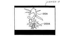
図12のフェーズF1では、遊戯者によるコントロールからの弾丸発射等の入力をCPUは受け付けず、S600からS604までの移動エリアの選択、武器選択の結果を起こるシーンの再生のみがCPUによって実行される。したがって、ロールプレイングゲームの特性として明かであるが、このフェーズの間は例えば、シネマスコープ(商標)を表示することによって、この間遊戯者側は入力が不可能なことを知ることができる。図19は、画面にシネマスコープが表示されている状態を示している。このシネマスコープは、遊戯者に対して入力不可状態を示す掲示手段として機能する。 In the phase F1 of FIG. 12, the CPU does not accept an input such as bullet firing from the control by the player, and only the reproduction of the scene that causes the selection of the moving area from S600 to S604 and the weapon selection is executed by the CPU. . Therefore, although it is clear as a characteristic of the role-playing game, during this phase, for example, by displaying Cinemascope (trademark), the player can know that input is impossible during this time. FIG. 19 shows a state where a cinemascope is displayed on the screen. This cinema scope functions as a posting means for indicating an input impossible state to the player.
図19のシネマスコープは、また、リアルタイムの戦闘シーンにおいて時計の進みを止めることと、遊戯者に技や攻撃をプレイヤキャラクタから敵キャラクタに繰り出すことが入力不可状態にあることを知らしめる情報伝達手段でもある。遊戯者はシネマスコープの画面によって、リアルタイムの戦闘シーンから或期間入力不可状態にあることを知ることができる。例えば、図19は、敵キャラクタ100Aからプレイヤキャラクタ200Aに攻撃が行われ、プレイヤキャラクタに攻撃命中の処理を施した映像である。この映像が表示されている間、時間の進行を止めて、一定時間プレイヤキャラクタから攻撃が行えないようにしている。
The cinemascope of FIG. 19 also informs the player that it is in an input impossible state to stop the advancement of the clock in the real-time battle scene and to send out the technique or attack from the player character to the enemy character. But there is. The player can know from the cinema scope screen that he / she has been unable to input for a certain period of time from a real-time battle scene. For example, FIG. 19 is an image in which an attack is performed on the
また、ロールプレイングゲームでは、遊戯者側の手番と対戦者側の手番が存在する。よって手順としては、「プレイヤキャラクタ側のフェーズF1」と「プレイヤキャラクタ側のフェーズF2」、「相手側のフェーズF1」、「相手側のフェーズF2」「プレイヤキャラクタ側のフェーズF1」・・・の手順のように、図12のフローチャートをプレイヤキャラクタ側と敵側との手順の流れに分けることができる。 In the role playing game, there are a player's turn and an opponent's turn. Therefore, the procedures are as follows: “Phase F1 on the player character side”, “Phase F2 on the player character side”, “Phase F1 on the opponent side”, “Phase F2 on the opponent side”, “Phase F1 on the player character side”,. Like the procedure, the flowchart of FIG. 12 can be divided into a procedure flow between the player character side and the enemy side.
なお、この明細書において、「予想」とは遊戯者やこの遊戯者に対する対戦者の意志であることは勿論であるが、ゲーム装置側がプレイヤキャラクタ側になって遊戯者が敵キャラクタ側である場合は、ゲーム装置による予想のことである。また、「予想」とは、遊戯者が敵の攻撃を避けようとする積極的意志(前述のシリンダのブロック間移動)を遊戯者が持つ場合、敵キャラクタの攻撃そのものを破壊する積極的意志(敵弾への応戦)持つ場合の他、適当に、ランダムにプレイヤキャラクタの位置やカーソルの位置を決め、結果的に敵キャラクタによる攻撃を避けるようなことができた場合をも含む。 In this specification, “anticipation” is, of course, the will of the player or the opponent for the player, but the game device side is the player character side and the player is the enemy character side. Is the prediction by the game device. “Prediction” means that if a player has a positive will to avoid an enemy attack (the movement of the cylinder between the blocks described above), the player will have a positive will to destroy the enemy character's attack ( In addition to the case of having a response to enemy bullets, it also includes the case where the position of the player character and the cursor position are appropriately determined at random, and as a result, the attack by the enemy character can be avoided.
次に、ゲーム機の戦闘シーンのさらに他の特徴的動作について説明する。図20はこの特徴的動作を説明するための模式図(戦闘シーンの一画面)に相当するものである。プレイヤキャラクタ200Aから敵キャラクタ100Aを攻撃できる部位をコリジョン点と定義し、このコリジョン点にシューティングゲームにおいて公知のロックオンカーソルLCをロックオンさせてプレイヤキャラクタから敵キャラクタに攻撃が行われるようにしている。
Next, still another characteristic operation of the battle scene of the game machine will be described. FIG. 20 corresponds to a schematic diagram (one screen of a battle scene) for explaining this characteristic operation. A part that can attack the
ここで、コリジョンとは、キャラクタの一つのしてのゲームプログラム上の弾や光線が敵キャラクタ或いはプレイヤキャラクタに当たる(両座標の一致または重なり)ことをいい、コリジョン点とはコリジョンが起こった箇所或いは起こるべき箇所をいう。 Here, the collision means that a bullet or light ray on the game program as one of the characters hits the enemy character or the player character (coincidence or overlap of both coordinates), and the collision point is the location where the collision occurred or Say where it should happen.
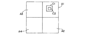
このコリジョン点は、例えば、敵キャラクタの前後左右の計4箇所(C1〜C4)に設定されており、プレイヤキャラクタから観て近いコリジョン点順にロックオンカーソルがロックオンする。図21に示すように、プレイヤキャラクタから見えるコリジョン点、敵キャラクタのコリジョン点のうちプレイヤキャラクタ側にある、すなわち仮想カメラの視野領域に入っている、または遊戯者から観ることができるコリジョン点にロックオンが可能となる。 The collision points are set, for example, at a total of four locations (C1 to C4) before and after the enemy character, and the lock-on cursor is locked on in the order of the collision points as viewed from the player character. As shown in FIG. 21, the collision point that can be seen by the player character and the collision point of the enemy character that is on the player character side, that is, that is in the visual field of the virtual camera or that can be watched by the player. It can be turned on.
このコリジョンをスイッチオンしたコリジョン点とし、プレイヤキャラクタから見えない、すなわち、プレイヤキャラクタとは反対側にあるコリジョンをオフされたコリジョン点とする。 This collision is a switched-on collision point, and a collision point that is invisible to the player character, that is, on the opposite side of the player character is a turned-off collision point.
図21の(3)の場合を例にとって説明すると、尾以外のコリジョン点はオンされて、オンされたコリジョンに許容される数のカーソルがロックオンすることができる。図20はカーソルがコリジョン点にロックオンされている状態を示している。 The case of (3) in FIG. 21 will be described as an example. Collision points other than the tail are turned on, and the number of cursors allowed for the turned on collision can be locked on. FIG. 20 shows a state where the cursor is locked on at the collision point.
図22は、このロックオン機能のフローチャートの一例を示すものであり、先ず、S22.2では、前記シリンダ様領域内の前後左右のどのブロックにプレイヤキャラクタ(ドラゴン)が位置するかが決定される。次いで、ブロックの位置からオン或いはオフとなるコリジョン点を決定し(S22.4)、オンとなったコリジョン点の座標データから、オンコリジョン点のドラゴンに対する遠近を決定する(S22.6)。 FIG. 22 shows an example of a flowchart of this lock-on function. First, in S22.2, it is determined in which block of the front, rear, left and right in the cylinder-like area the player character (dragon) is located. . Next, a collision point that is turned on or off is determined from the position of the block (S22.4), and the perspective of the on-collision point with respect to the dragon is determined from the coordinate data of the collision point that is turned on (S22.6).
既述のように最もドラゴンに近いコリジョン点にカーソルがロックオンしたことを示すフラグ「1」を立てる(S22.8)。この後、全数のロックオンカーソル数がロックオンしたか否かが立ったフラグ数によって判定され(S22.10)、次いで、全オンコリジョンにフラグが立ったか否かが判定される(S22.12)。S22.10でロックオン数が最大値に達したときには、以後のロックオンが行われることなく、遊戯者がコントローラの引き金をオンしたか否かの判定に移行する(S22.14)。 As described above, the flag “1” indicating that the cursor is locked on is set at the collision point closest to the dragon (S22.8). Thereafter, whether or not all the lock-on cursors are locked on is determined based on the number of flags that are set (S22.10), and then whether or not all on-collisions are flagged is determined (S22.12). ). When the number of lock-on reaches the maximum value in S22.10, the process proceeds to the determination of whether or not the player has turned on the trigger of the controller without performing the subsequent lock-on (S22.14).
S22.10でロックオン数が最大値に達することがなく、且つ、S22.12で全コリジョンがロックオンされていないときには、S22.16に移行してフラグが立っていないコリジョン点が決定されて、このコリジョン点の中から最も近いコリジョン点にフラグを立てる。S22.12で全コリジョンがロックオンされたときには、S22.14に移行してトリガーのオン又はオフが判定される。S22.14でトリガーオンされたときには、S22.18に移行してドラゴンから敵キャラクタのコリジョン点にロックオンしたロックオンカーソルに向けて仮想の誘導弾や光線弾が飛散する攻撃シーンの画像が合成されてモニタに表示される。一方、遊戯者が所定時間内にトリガーをオンしない場合には、S22.18をスキップしてリターンする。 When the lock-on number does not reach the maximum value in S22.10 and all the collisions are not locked-on in S22.12, the process proceeds to S22.16, and the collision point where the flag is not set is determined. A flag is set to the closest collision point among the collision points. When all the collisions are locked on in S22.12, the process proceeds to S22.14 to determine whether the trigger is on or off. When the trigger is turned on in S22.14, the process proceeds to S22.18, and an image of an attack scene in which a virtual guided bullet or ray bullet scatters toward the lock-on cursor locked on from the dragon to the collision point of the enemy character is synthesized. Displayed on the monitor. On the other hand, if the player does not turn on the trigger within the predetermined time, the process skips S22.18 and returns.
この処理動作によれば、敵キャラクタのコリジョンの中でもプレイヤキャラクタであるドラゴン側にあるコリジョン点のみ、又はドラゴン側に近いコリジョン点に攻撃を仕掛けることができるために、例えば、遊戯者から見えないコリジョン点に攻撃がなされるようなことを避けることができる。 According to this processing operation, it is possible to attack only the collision point on the dragon side which is the player character among the collisions of the enemy character or the collision point close to the dragon side. It is possible to avoid the point being attacked.
コリジョン点は遊戯者から攻撃できる箇所を多彩にするために、敵キャラクタの前後左右に複数設定される。敵キャラクタが複数のオブジェクト(頭、胴、尾等)から構成される場合には、個々のオブジェクトに対して設定できる。 A plurality of collision points are set on the front, back, left and right of the enemy character in order to make various points that can be attacked by the player. When the enemy character is composed of a plurality of objects (head, torso, tail, etc.), it can be set for each object.
コリジョン点には、コリジョンの性格毎に「重み」を付けることができる。例えば、ある特定の箇所のコリジョンを敵キャラクタの弱点に相当するコリジョンとすることができる。このコリジョンへの攻撃が成功すると、敵キャラクタには多くのダメージが与えられたものとする。この時、コリジョンの重みの相違によってロックオンカーソルの形や色彩を変えるようにしても良い。 A “weight” can be attached to the collision point for each character of the collision. For example, a collision at a specific location can be a collision corresponding to a weak point of an enemy character. If the attack on the collision is successful, the enemy character is assumed to have received a lot of damage. At this time, the shape and color of the lock-on cursor may be changed depending on the collision weight.
このコリジョン点はその位置や重みが固定された静的なものから、コリジョン点の位置や重みが変化する動的なものであっても良い。すなわち、時間を経て、あるいはゲームの得点や、プレイヤキャラクタや敵キャラクタのポイントに応じて或コリジョン点が消滅したり、或いはコリジョン点の位置が変わったり、また、コリジョン点の重みが変化したりである。図11のように敵キャラクタが複数体存在する場合には、コリジョン点は敵キャラクタ毎に設定されることが良い。コリンジョン点よりロックオンカーソル数が多い場合には、或コリジョンに複数のロックオンカーソルが重なっても良い。 The collision point may be a static one whose position and weight are fixed, or a dynamic one whose position and weight change. That is, the collision point disappears, the position of the collision point changes, or the weight of the collision point changes depending on the score of the game, the point of the player character or the enemy character, etc. is there. When there are a plurality of enemy characters as shown in FIG. 11, the collision point is preferably set for each enemy character. If the number of lock-on cursors is greater than the collision point, a plurality of lock-on cursors may overlap with a collision.
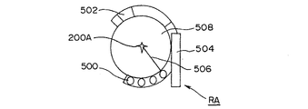
前記レーダの他の例として、図23に示すような多情報を表示可能な形態のものがある。図24はそれの表示例である。このレーダーRAは、中央にプレイヤキャラクタとしてのドラゴンを配置して、その回りに各種多彩の情報を表示するためのシンボルを置いている。 As another example of the radar, there is a type capable of displaying multiple information as shown in FIG. FIG. 24 shows a display example thereof. In this radar RA, a dragon as a player character is placed in the center, and symbols for displaying various information are placed around it.
500はドラゴンが仮想空間内を飛行している時の飛行速度を示す仮想ゲージである。502は、目的地或いは目的方向を示すものであり、これをほぼ中心に捉えていれば目的地に向けてドラゴンを飛行させることができる。
また、504は、仮想な海抜点に対するドラゴンの飛行高度を示すものである。さらに506は、ドラゴンの飛行方向に対するマップの北方向を表すものであり、508はドラゴンが既述の戦闘シーンに移行する率、エンカウント率に相当する形態を表示する領域である。この508の領域に、敵乃至イベントポイント(街、セーブポイント)の表示を加えても良い。
エンカウント率が高いと近い将来戦闘シーンに移行する確率が高いことを示す。このエンカウント率の変化を領域508の形態、例えば、背景色を変化させることによって遊戯者に伝えることができる。エンカウント率はドラゴンが飛行する位置によって異なる。この表示レーダは、ロールプレイングのゲームプログラム処理中の画面に主として表示される。遊戯者はエンカウント率をモニタしながら、敵キャラクタとの遭遇を望むか、或いはドラゴンを目的地に対して例えば遠回りさせても敵キャラクタとの遭遇を避けるようにするかを適宜判断しながら、ドラゴンを操作する。
A high encounter rate indicates a high probability of transition to a battle scene in the near future. This change in the encounter rate can be transmitted to the player by changing the form of the
ドラゴンから敵キャラクタへの攻撃は、図11に示す武器ゲージ110の容量が満杯になった映像が完成したときに可能となる。従来のものでは、このような武器ゲージとして武器の種類毎に複数設けるようにしたものが存在したが、本願発明ではこれを一本化したことを特徴とする。
The attack from the dragon to the enemy character becomes possible when the image in which the capacity of the
図36はゲージ110に仮想的なエネルギーが溜まって行く過程を(1)から(7)進むように示したものである。先ず(1)から(3)の過程で、白地のゲージに所定色の第1エネルギーが充填される。ゲージの右端まで色が反転するとゲージへのエネルギー充填完了とされる。次に、(4)から(5)の過程で異なった色の第2エネルギーが溜まって行く。さらに(6)から(7)の過程でさらに異なった色の第3エネルギーが溜まっていく。それぞれのエネルギーが溜まった(3),(4),(5)でゲージポイントがそれぞれ1,2,3とされ、それぞれゲージポイント毎に武器プライオリティが1,2,3が与えられる。
FIG. 36 shows the process in which virtual energy accumulates in the
武器プライオリティが高い程、ドラゴンは高度な技や武器を敵キャラクタに向けて繰り出すことができる、或いは同じ武器の場合は数多く繰り出すことができる等である。 The higher the weapon priority, the more the dragon can advance advanced techniques and weapons toward the enemy character, or the more the same weapons can be delivered.
遊戯者は、ゲージの色が反転して行く過程を認識することによって自分が選択できる技や武器を知ることが出来る。遊戯者がコントローラのトリガーをオンすることによって、トリガーオンの時のポイントに応じて繰り出す武器や技の数や種類が決定される。 The player can know the techniques and weapons that he can select by recognizing the process of the gauge color inverting. When the player turns on the trigger of the controller, the number and types of weapons and techniques to be paid out are determined according to the points when the trigger is turned on.
ゲージポイントが「3」の時では、遊戯者が望むときには同じ武器を連続3回発射できる。従来のようにゲージが一度溜まる毎に一回の攻撃が選択できるに過ぎない場合に比較すると、遊戯者にとって攻撃の態様が増し、短い時間に多くの敵キャラクタを倒す必要がある場合に備えることができる。 When the gauge point is “3”, the same weapon can be fired three times in succession if the player desires. Compared to the case where only one attack can be selected each time the gauge is accumulated as in the conventional case, the player has more aspects of attack and is prepared for a case where it is necessary to defeat many enemy characters in a short time. Can do.
ゲージが溜まっている途中でも、遊戯者はドラゴンを移動させることができる。また、武器を発射することもできる。遊戯者によるトリガーのオン指令を受けたCPUは、その時のゲージポイントから武器プライオリティを得、これから武器を選択して敵キャラクタに対して攻撃を与える。 The player can move the dragon even while the gauge is accumulating. You can also fire weapons. Upon receiving the trigger on command from the player, the CPU obtains the weapon priority from the gauge point at that time, selects a weapon from this, and attacks the enemy character.
トリガーオンの後、使用武器の量に応じてゲージポイントが減じられる。例えば、図36(4)の時から1ゲージポイント分の武器が使用されると(2)の状態にまで戻る。また、(6)の状態からだと1ゲージポイント分の武器使用の場合(4)に戻り、2ゲージポイント分であると(2)の状態に戻る。 After trigger on, gauge points are reduced according to the amount of weapons used. For example, when the weapon for 1 gauge point is used from the time of FIG. 36 (4), it will return to the state of (2). In the state of (6), when the weapon is used for 1 gauge point, the process returns to (4).
ゲージには所定の時間速度で順次仮想エネルギーが充填されるようになっており、ゲージポイントが減じられても、順次ゲージにエネルギーが充填されて行く。但し、(7)のゲージポイント3が最大値であるので、これ以上のポイント増加はないものとする。
The gauge is sequentially filled with virtual energy at a predetermined time rate, and even if the gauge point is reduced, the gauge is sequentially filled with energy. However, since the
このように従来複数のゲージを一本化することにより、遊戯者は敵キャラクタに対する武器選択を複数のゲージを常時チェックする煩わしさから開放される効果がある。なお、ゲージの機能としては武器選択に限らず、プレイヤキャラクタの行動様式の選択や敵キャラクタの選択等、ゲージのポイント毎に異なる映像を合成するようなもの、異なるシミュレートを実行するようなもの等特に限定されるものではない。 Thus, by integrating a plurality of gauges conventionally, there is an effect that the player is freed from the trouble of constantly checking the plurality of gauges when selecting weapons for enemy characters. Note that the gauge function is not limited to weapon selection, such as selecting a player character's action style or selecting an enemy character, such as combining different images for each gauge point, or performing different simulations. It is not particularly limited.
ここで、説明した新規ゲージの他の態様として、図37に記載するものも存在する。このものでは、左から右にかけて色彩が順次一回反転して行くものであり、左側のブロックの右端まで反転するとゲージポイントが1であり、真ん中のブロックの右端までだとポイント2であり、さらに右のブロックの右端までであるとゲージポイントが3である。 Here, as another aspect of the new gauge described, there is one described in FIG. In this, the color is reversed once from the left to the right, the gauge point is 1 when it is reversed to the right end of the left block, the point is 2 when it is up to the right end of the middle block, and The gauge point is 3 if it is to the right end of the right block.
前記RAM102には、このゲージポイントを記録するための所定の記録領域が設けられており、武器が使用されるとゲージポイントが1づつデクリメントされ、また、所定時間経過するとゲージポイントが1インクリメントされ、それぞれの結果が記録されている。ゲージポイントを超える武器発射コマンドがCPU101に入力されても、CPUはこのコマンドを無視し、ゲージポイントが溜まった後のコマンド入力に応答して武器を発射するようにしている。
The
なお、ゲージを塗り替える回数は3回に限る必要はない。また、プレイヤキャラクタが複数存在する場合、武器や行動の他に、武器や行動をするキャラクタを選択可能である。 The number of times the gauge is repainted need not be limited to three. Further, when there are a plurality of player characters, in addition to weapons and actions, it is possible to select characters that perform weapons and actions.
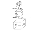
次に、敵キャラクタの回りに形成される区画領域の他の例について説明する。ここでは、既述のシリンダ様領域に代えて、正6面体(キュービック)様領域にした点に特徴がある。この正6面体の少なくとも一面にプレイヤキャラクタが配置される。また、ある面にプレイヤキャラクタを配置し且つ他の面に敵キャラクタが配置される。 Next, another example of the partition area formed around the enemy character will be described. Here, there is a feature that a regular hexahedron (cubic) -like region is used instead of the above-described cylinder-like region. A player character is arranged on at least one side of the regular hexahedron. In addition, a player character is placed on a certain face and an enemy character is placed on the other face.
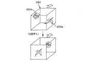
図25は、この一例を示すものであり敵キャラクタをキュービック240のある面に配置し、プレイヤキャラクタをその面に対向する面に配置している。敵キャラクタ及びプレイヤキャラクタは、キュービックの側面の4面の表面を移動できる。図26は、プレイヤキャラクタや敵キャラクタをキュービックに配置するためのフローチャートを示すものである。 FIG. 25 shows an example of this, in which the enemy character is placed on the surface where the cubic 240 is located, and the player character is placed on the surface facing the surface. The enemy character and the player character can move on the four surfaces of the cubic side. FIG. 26 shows a flowchart for arranging player characters and enemy characters in a cubic manner.
先ず、S25.0では図3の戦闘シーンに移行したときに、キュービックの初期形態が決定される。キュービックの初期形態は、主に敵キャラクタとプレイヤキャラクタとの距離に基づいて決定される。両者の距離が大きくなるにしたがって、キュービックが大きくなるに決定される。 First, in S25.0, when the battle scene of FIG. 3 is entered, an initial form of cubic is determined. The initial form of cubic is determined mainly based on the distance between the enemy character and the player character. The cubic is determined to increase as the distance between the two increases.
敵キャラクタに対するキュービックを配置する態様には、各種のものを考えることができる。図27は既述のシリンダ様領域のように、敵キャラクタ100Aをキュービックの下面の中心に置いてプレイヤキャラクタ200Aをキュービックの右側面に配置したことを示している。また、敵キャラクタから離れた位置にキュービックを配置するようにしても良い。さらに、また、キュービックの重心位置に敵キャラクタを配置するようにしても良い。
Various modes can be considered for the arrangement of cubics for enemy characters. FIG. 27 shows that the
図3で説明した戦闘シーンでは、プレイヤキャラクタが敵キャラクタに対して有利な位置を採るように、プレイヤキャラクタと敵キャラクタとの位置取りが行われる。そこで、このような位置取りを容易に実現するため、図28を参照しながらさらにフローチャートを説明する。 In the battle scene described with reference to FIG. 3, the player character and the enemy character are positioned so that the player character takes an advantageous position with respect to the enemy character. Therefore, in order to easily realize such positioning, a flowchart will be further described with reference to FIG.
S25.2では、キュービックが所定速度を持って仮想空間としてのワールド座表系を進行する処理が行われる。既述のように、このキュービックも図3のパス16Aに沿って移動することとする。すなわち、ドラゴンと敵キャラクタの動きに合わせて、キュービックの位置が補正される。図28は、その過程を示すものである。
In S25.2, processing is performed in which the cubic advances in the world coordinate system as a virtual space with a predetermined speed. As described above, this cubic is also moved along the
ドラゴンと敵キャラクタとが初期位置に在る状態からドラゴンが敵キャラクタに対して前方向に進むと、ドラゴンと敵キャラクタとを結ぶ直線の中心にキュービックの中心が来るようにキュービックの全体の位置が前進された補正が実行される。図の破線は補正前のキュービックの位置を示すものであり、図の実線はドラゴンの進行分に応じて前方に進行したキュービックの位置を示すものである。 When the dragon and the enemy character are in the initial position and the dragon moves forward with respect to the enemy character, the overall position of the cubic is such that the center of the cubic comes to the center of the straight line connecting the dragon and the enemy character. The advanced correction is performed. The broken line in the figure indicates the position of the cubic before correction, and the solid line in the figure indicates the position of the cubic that has advanced forward according to the progress of the dragon.
キュービックの形態は、また、必要に応じて変形される(S25.4)。キュービックの変形が必要な場合とは、ドラゴンと敵キャラクタとの距離に応じて初期形態のキュービックの形態が変更される場合である。図29は両者が比較的離れた場合に径が大きくなるようにキュービックが変形され、また、両者の距離が比較的小さくなった場合、キュービックの径をそれに合わせて小さくなるようにした場合を示したものである。 The cubic form is also modified as necessary (S25.4). The case where the cubic deformation is necessary is a case where the cubic form of the initial form is changed according to the distance between the dragon and the enemy character. FIG. 29 shows a case where the cubic is deformed so that the diameter increases when the two are relatively apart from each other, and when the distance between the two is relatively small, the diameter of the cubic is reduced accordingly. It is a thing.
キュービックの変形の第2の場合は、キュービックが通るルートに応じてキュービックの径が変形することである。図30はルートの幅290が狭い場合に、キュービックの幅を小さくした場合を示す。図30の場合には、キュービックとルートとの衝突判定がチェックされて、衝突判定が肯定された場合にキュービックを衝突判定が判定が否定されるようになるまで、所定の値ずつキュービックの一辺の長さが減じられることとする。
The second case of cubic deformation is that the cubic diameter is deformed according to the route through which the cubic passes. FIG. 30 shows a case where the cubic width is reduced when the
次いで、敵キャラクタとドラゴンとの位置替えステップ(S25.6)に移行する。このステップでは、図28で示すドラゴンの位置変化の過程で、ドラゴンと敵キャラクタがキュービックのコーナーの座標に近づいた際、コーナーとドラゴン又プレイヤキャラクタとの距離が所定値以下になったとき位置替えのためのフラグを立てて、CPU101はドラゴンをキュービックの前面の中心に移し、かつ敵キャラクタをこの前面に対向する後面の中心に強制的に移す処理を行う。
Next, the process proceeds to the position changing step (S25.6) between the enemy character and the dragon. In this step, when the dragon and the enemy character approach the coordinates of the cubic corner in the process of changing the dragon position shown in FIG. 28, the position is changed when the distance between the corner and the dragon or the player character becomes a predetermined value or less. The
この時、プレイヤキャラクタと敵キャラクタとの間の距離が補正される。ドラゴンと敵キャラクタがキュービックのコーナーに近づくまで位置替えを伴うことなくキュービックが前進する。 At this time, the distance between the player character and the enemy character is corrected. Cubic moves forward without repositioning until the dragon and enemy character approach the cubic corner.
この位置替えは、既述の4面の間で行われるが、上下面に位置替えが及ぶものであっても良い。後者の場合は、キュービックの上下面にも敵キャラクタ及びプレイヤキャラクタが移動する。仮想カメラがプレイヤキャラクタと敵キャラクタの後ろからこれらを撮影するシステムである関係上、キャラクタの移動が上下面に及ぶとドラゴンや敵キャラクタの映像が鏡像のように逆転する可能性もある。 This position change is performed between the four surfaces described above, but the position change may extend to the upper and lower surfaces. In the latter case, the enemy character and the player character also move on the upper and lower surfaces of the cubic. Since the virtual camera is a system that captures these images from behind the player character and enemy character, if the character moves up and down, the image of the dragon or enemy character may be reversed like a mirror image.
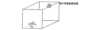
S25.8において、プレイヤキャラクタ或いは敵キャラクタのキュービックにおける位置を制限することが必要な場合には、例えば図31に示すようにドラゴンの移動範囲をキュービックの下面寄りにするとともに、敵キャラクタの移動範囲をキュービックの上面寄りにする。また、図32,図33に示すように、ドラゴンをキュービックの上面寄りで敵キャラクタをその下面寄りにする。このようにすると、例えば敵キャラクタがプレイヤキャラクタに比べて長い場合(図33)に、両者が交錯しないようにしている。ドラゴンや敵キャラクタの移動範囲を制限することは、それぞれが移動できる座標値を指定して実行される。このような制限は、シリンダ様形状を利用した先に説明した実施の形態にも適用できることは当然である。このとき、シリンダの長径や短径の長さを自由に設定できる。シリンダの上下の幅に制限を設けることにより、ドラゴンの飛行範囲を制限することによることに基づき、遊戯者が敵キャラクタやプレイヤキャラクタを制御することを容易にしたり、又はゲームの展開(敵キャラクタとプレイヤキャラクタとの空間的な係わり合い等)を多様化することができる。 In S25.8, if it is necessary to limit the position of the player character or enemy character in the cubic, for example, as shown in FIG. 31, the movement range of the dragon is made closer to the lower surface of the cubic, and the movement range of the enemy character. Move closer to the top of the cubic. Also, as shown in FIGS. 32 and 33, the dragon is placed closer to the upper surface of the cubic and the enemy character is placed closer to the lower surface. In this way, for example, when the enemy character is longer than the player character (FIG. 33), both are prevented from intermingling. Limiting the movement range of dragons and enemy characters is performed by specifying coordinate values that each can move. Of course, such a limitation can be applied to the above-described embodiment using a cylinder-like shape. At this time, the length of the major axis and minor axis of the cylinder can be freely set. By limiting the upper and lower widths of the cylinder, it is possible to make it easier for the player to control enemy characters and player characters based on limiting the flight range of the dragon, The spatial relationship with the player character can be diversified.
既述の実施形態は、プレイヤキャラクタと敵キャラクタとの間の戦闘(射撃)をシミュレートするゲーム機について説明されたが、本発明が適用できるものでれば、ゲームプログラムの種類が限定されるものではない。例えば、既述の予測動作をサッカーゲームに於けるPK戦の時のゴールキーパーによる相手チームからのキックに対する防御に応用することができる。また、シューティングの他の戦闘ゲームとしての格闘ゲームにも適用できる。 In the above-described embodiment, a game machine that simulates a battle (shooting) between a player character and an enemy character has been described. However, if the present invention is applicable, the types of game programs are limited. It is not a thing. For example, the above-described prediction operation can be applied to defense against a kick from an opponent team by a goalkeeper at the time of a PK match in a soccer game. It can also be applied to fighting games as other shooting games for shooting.
また、コリジョンの説明は、戦闘ばかりでなく、コマンドRPG等のゲームに使用することもできる。 The description of collision can be used not only for battle but also for a game such as a command RPG.
また、既述の実施形態では、プレイヤキャラクタ或いはカーソルの移動を所定の領域に自動的に移動される場合について説明したが、これを遊戯者が自身で所定領域に予め移動させるようにすることも本発明に含まれるものである。 In the above-described embodiment, the case where the movement of the player character or the cursor is automatically moved to the predetermined area has been described. However, the player may move the character to the predetermined area by himself / herself. It is included in the present invention.
またさらに、キャラクタの設定先は、エリア毎に分かれたものでなく、例えば、決められたポイント(ある特定の空間座標箇所)であっても良い。要するに、事前に決められた箇所、領域或いは位置であれば良い。この箇所は、空間座標系に定義され、或いは画面座標系に定義され得る。またさらに、本発明を2次元座標系を基準としてスプライトゲームに適用することもできる。 Furthermore, the setting destination of the character is not divided for each area, but may be a predetermined point (a specific spatial coordinate location), for example. In short, any place, region, or position determined in advance may be used. This location may be defined in the spatial coordinate system or may be defined in the screen coordinate system. Furthermore, the present invention can be applied to a sprite game based on a two-dimensional coordinate system.
なお、ゲーム機の動作用プログラムが記憶された記憶媒体としては、既述のカートリッジROM、CD−ROMの他にインターネット、パソコンネット上の通信媒体でも良い。また、前記移動キャラクタの移動先を複数の領域に分けるようにすることもできる。 The storage medium storing the game machine operation program may be a communication medium on the Internet or a personal computer network in addition to the cartridge ROM and CD-ROM described above. Further, the moving character can be divided into a plurality of areas.
また、所定の空間域としては、既述のシリンダ形状とキュービックの他に6面体を越える多角形や球状形であっても良い。 In addition to the cylinder shape and cubic described above, the predetermined space area may be a polygon or a spherical shape exceeding a hexahedron.
また、既述の実施形態では、エンカウントを戦闘(シューティングの上位概念)の処理モードに移行するための情報として説明したが、シューティングの他にアクション・格闘ゲーム、ゲームプログラム上の街での情報収集やストーリ展開のドラマ等の種々のゲームプログラムでよい。また、ロックオンカーソルの重み付けについて、敵キャラクタが複数の場合、種類が異なる仮想体の場合、各キャラクタ毎にコリジョンが設定されるだけでなく、そのキャラクタの種類によってロックオンカーソルが変わる、例えば、先に倒すことが有利なキャラクタに重み付けのカーソルが表示されるようにしても良い。すなわち、本願発明ではロックオンカーソルに重みを付けたカーソルが複数設定されて、敵キャラクタ種類や数に応じて重みを付けたカーソルを表示することができる。 Further, in the above-described embodiment, the explanation has been given as information for shifting the encounter to the processing mode of battle (superior concept of shooting). However, in addition to shooting, information on the city on the action / fighting game and game program Various game programs such as drama for collection and story development may be used. Regarding the weight of the lock-on cursor, when there are a plurality of enemy characters, in the case of virtual bodies of different types, not only the collision is set for each character, but the lock-on cursor changes depending on the type of the character, for example, A weighted cursor may be displayed on a character that is advantageous to be defeated first. That is, in the present invention, a plurality of cursors weighted to the lock-on cursor are set, and the cursor weighted according to the enemy character type and number can be displayed.
1 ゲーム機本体(データ処理装置)
2b ペリフェラル
5 TV受像機
5a スピーカ
10 CPUブロック
11 ビデオブロック
12 サウンドブロック
13 サブシステム
100 SCU
101 メインCPU
104 サブCPU
120 第1のVPD
122、123 フレームバッファ
130 第2のVDP
130a レジスタ
130b カラーRAM
131 VRAM
132 フレームメモリ
160 エンコーダ
170 D/Aコンバータ
200 画像処理系
1 Game console (data processing device)
101 Main CPU
104 Sub CPU
120 First VPD
122, 123
131 VRAM
132
Claims (9)
前記CPUが、前記ゲームアプリケーションソフトに基づいて、前記オブジェクトの形態に応じた大きさの所定の三次元立体形状を成し、複数のブロックエリアに分割された空間域を、前記オブジェクトの周囲に設定する第1のステップと、
前記CPUが、前記ゲームアプリケーションソフトに基づいて、前記プレイヤキャラクタを前記ブロックエリアの前記空間域の表面に配置する第2のステップと、
前記CPUが、前記ゲームアプリケーションソフト及び操作入力部からの入力信号に基づいて、前記プレイヤキャラクタを前記ブロックエリアの前記空間域の表面上を移動させると共に、前記プレイヤキャラクタを一の前記ブロックエリアから他の前記ブロックエリアに移動させる際には、前記プレイヤキャラクタを当該他のブロックエリアの特定位置に移動させる第3のステップと
を備えることを特徴とする画像処理方法。 When the CPU executes game application software, a predetermined object and a player character are arranged in the virtual space, the game is advanced by controlling the movement and position of the player character and the object, and the three-dimensional virtual space An image processing method of a game image in a game device configured to output a screen as seen from a position of a predetermined viewpoint to a display means as a game image,
Based on the game application software, the CPU forms a predetermined three-dimensional solid shape having a size corresponding to the form of the object, and sets a space area divided into a plurality of block areas around the object A first step to:
A second step in which the CPU places the player character on the surface of the space area of the block area based on the game application software ;
The CPU moves the player character on the surface of the space area of the block area based on the game application software and an input signal from the operation input unit, and moves the player character from one block area to another. An image processing method comprising: a third step of moving the player character to a specific position in the other block area when moving to the block area.
前記オブジェクト及び前記プレイヤキャラクタを、前記仮想空間内に設けられたパスに沿って移動させる処理を含む
ことを特徴とする請求項1に記載の画像処理方法。 The third step includes
The image processing method according to claim 1, further comprising a process of moving the object and the player character along a path provided in the virtual space.
前記空間域を前記オブジェクトごとに設定する
ことを特徴とする請求項1又は請求項2に記載の画像処理方法。 In the first step,
The image processing method according to claim 1, wherein the space area is set for each object.
前記オブジェクトから前記プレイヤキャラクタに向かって所定の移動キャラクタを移動させる処理を含む
ことを特徴とする請求項1乃至請求項3の何れか1項に記載の画像処理方法。 The third step includes
The image processing method according to claim 1, further comprising a process of moving a predetermined moving character from the object toward the player character.
前記CPUは、前記移動キャラクタの移動表示処理中前記操作入力部からの入力を受け付けないように処理する
ことを特徴とする請求項4に記載の画像処理方法。 In the third step,
The image processing method according to claim 4, wherein the CPU performs a process so as not to accept an input from the operation input unit during the movement display process of the moving character.
前記第3のステップにおいて、
前記CPUは、前記ブロックエリア毎に前記敵キャラクタが発射する前記移動キャラクタとしての弾丸の射出方向を設定する
ことを特徴とする請求項4又は請求項5に記載の画像処理方法。 The game application software relates to a battle scene between the player character and an enemy character composed of the object,
In the third step,
6. The image processing method according to claim 4 or 5, wherein the CPU sets an ejection direction of a bullet as the moving character fired by the enemy character for each block area .
前記第3のステップにおいて、
前記CPUは、前記敵キャラクタの弱点領域を設定する
ことを特徴とする請求項1乃至請求項6の何れか1項に記載の画像処理方法。 The game application software relates to a battle scene between a player character and an enemy character composed of the object,
In the third step,
The image processing method according to any one of claims 1 to 6, wherein the CPU sets a weak spot area of the enemy character.
前記プレイヤキャラクタと前記オブジェクトとの前記空間域における位置を示す模擬レーダを前記表示手段に表示する処理を含む
ことを特徴とする請求項1乃至請求項7の何れか1項に記載の画像処理方法。 The third step includes
8. The image processing method according to claim 1, further comprising: displaying on the display unit a simulated radar indicating a position of the player character and the object in the space area. .
ことを特徴とする請求項1乃至請求項8の何れか1項に記載の画像処理方法。 The image processing method according to claim 1, wherein the space region is formed in a cylindrical shape or a cubic shape.
Priority Applications (1)
| Application Number | Priority Date | Filing Date | Title |
|---|---|---|---|
| JP2004097357A JP3736767B2 (en) | 1997-01-30 | 2004-03-30 | Image processing method |
Applications Claiming Priority (2)
| Application Number | Priority Date | Filing Date | Title |
|---|---|---|---|
| JP1722497 | 1997-01-30 | ||
| JP2004097357A JP3736767B2 (en) | 1997-01-30 | 2004-03-30 | Image processing method |
Related Parent Applications (1)
| Application Number | Title | Priority Date | Filing Date |
|---|---|---|---|
| JP9087493A Division JPH10272258A (en) | 1997-01-30 | 1997-03-23 | Picture processor |
Publications (2)
| Publication Number | Publication Date |
|---|---|
| JP2004230179A JP2004230179A (en) | 2004-08-19 |
| JP3736767B2 true JP3736767B2 (en) | 2006-01-18 |
Family
ID=32964197
Family Applications (1)
| Application Number | Title | Priority Date | Filing Date |
|---|---|---|---|
| JP2004097357A Expired - Fee Related JP3736767B2 (en) | 1997-01-30 | 2004-03-30 | Image processing method |
Country Status (1)
| Country | Link |
|---|---|
| JP (1) | JP3736767B2 (en) |
Families Citing this family (7)
| Publication number | Priority date | Publication date | Assignee | Title |
|---|---|---|---|---|
| JP4346625B2 (en) | 2006-04-28 | 2009-10-21 | 株式会社スクウェア・エニックス | Video game processing apparatus and video game processing program |
| JP4671196B2 (en) | 2006-10-31 | 2011-04-13 | 株式会社スクウェア・エニックス | NETWORK GAME SYSTEM, NETWORK GAME TERMINAL DEVICE, GAME SCREEN DISPLAY METHOD, PROGRAM, AND RECORDING MEDIUM |
| JP4651604B2 (en) | 2006-11-16 | 2011-03-16 | 株式会社スクウェア・エニックス | Video game processing apparatus and video game processing program |
| JP5235310B2 (en) * | 2007-02-16 | 2013-07-10 | 株式会社タイトー | Message transmission method and multiplayer game system using the transmission method |
| JP5594933B2 (en) * | 2007-12-25 | 2014-09-24 | 株式会社カプコン | Program and game system |
| KR101074670B1 (en) * | 2010-09-27 | 2011-10-18 | 우종걸 | Shooting game system using chroma key |
| JP6677788B1 (en) * | 2018-11-29 | 2020-04-08 | 株式会社Cygames | Information processing program, information processing method and game device |
-
2004
- 2004-03-30 JP JP2004097357A patent/JP3736767B2/en not_active Expired - Fee Related
Also Published As
| Publication number | Publication date |
|---|---|
| JP2004230179A (en) | 2004-08-19 |
Similar Documents
| Publication | Publication Date | Title |
|---|---|---|
| US6652384B2 (en) | Image processing device for placing a player character in a virtual space | |
| US6666764B1 (en) | Method of controlling a character in a video game | |
| JP3505705B2 (en) | Recording medium and game device | |
| US6540612B1 (en) | Video game system and video game memory medium | |
| JP5136742B2 (en) | Electronic game device, electronic game control method, and game program | |
| US6296570B1 (en) | Video game system and video game memory medium | |
| EP0808644B1 (en) | Object-throwing video game system | |
| JP4756632B2 (en) | GAME PROGRAM AND GAME DEVICE | |
| JP3745475B2 (en) | GAME DEVICE AND IMAGE PROCESSING DEVICE | |
| US20100009734A1 (en) | Electronic play device, control method for electronic play device and game program | |
| US20040046800A1 (en) | Electronic game and method for effecting game features | |
| JP2006314763A (en) | Competition video game control program | |
| JP4797439B2 (en) | GAME DEVICE AND PROGRAM | |
| JP7426462B2 (en) | Programs, game devices, server devices and game systems | |
| JP2001149640A (en) | Game machine, game processing method, and recording medium recording program | |
| JP2008093307A (en) | Electronic game device, control method for electronic game and game program | |
| JP3732497B2 (en) | Message output device, message control method, and program | |
| JP3736767B2 (en) | Image processing method | |
| JP4251589B2 (en) | Image generation system and information storage medium | |
| JP2003154163A (en) | Plotting control method, recoding medium, plotting controller and program | |
| JP3197536B2 (en) | GAME DEVICE, IMAGE DISPLAY CONTROL METHOD, AND RECORDING MEDIUM CONTAINING IMAGE DISPLAY CONTROL PROGRAM | |
| JP3753349B2 (en) | Information storage medium and image generation apparatus | |
| US6967650B1 (en) | Image generating system and program | |
| JP3378520B2 (en) | Video game apparatus and recording medium storing program | |
| JP3921361B2 (en) | Video game system and storage medium for video game |
Legal Events
| Date | Code | Title | Description |
|---|---|---|---|
| A131 | Notification of reasons for refusal |
Free format text: JAPANESE INTERMEDIATE CODE: A131 Effective date: 20050318 |
|
| A521 | Written amendment |
Free format text: JAPANESE INTERMEDIATE CODE: A523 Effective date: 20050517 |
|
| A131 | Notification of reasons for refusal |
Free format text: JAPANESE INTERMEDIATE CODE: A131 Effective date: 20050708 |
|
| A521 | Written amendment |
Free format text: JAPANESE INTERMEDIATE CODE: A523 Effective date: 20050906 |
|
| TRDD | Decision of grant or rejection written | ||
| A01 | Written decision to grant a patent or to grant a registration (utility model) |
Free format text: JAPANESE INTERMEDIATE CODE: A01 Effective date: 20051007 |
|
| A61 | First payment of annual fees (during grant procedure) |
Free format text: JAPANESE INTERMEDIATE CODE: A61 Effective date: 20051020 |
|
| R150 | Certificate of patent or registration of utility model |
Free format text: JAPANESE INTERMEDIATE CODE: R150 |
|
| FPAY | Renewal fee payment (event date is renewal date of database) |
Free format text: PAYMENT UNTIL: 20091104 Year of fee payment: 4 |
|
| FPAY | Renewal fee payment (event date is renewal date of database) |
Free format text: PAYMENT UNTIL: 20091104 Year of fee payment: 4 |
|
| FPAY | Renewal fee payment (event date is renewal date of database) |
Free format text: PAYMENT UNTIL: 20101104 Year of fee payment: 5 |
|
| FPAY | Renewal fee payment (event date is renewal date of database) |
Free format text: PAYMENT UNTIL: 20111104 Year of fee payment: 6 |
|
| FPAY | Renewal fee payment (event date is renewal date of database) |
Free format text: PAYMENT UNTIL: 20111104 Year of fee payment: 6 |
|
| FPAY | Renewal fee payment (event date is renewal date of database) |
Free format text: PAYMENT UNTIL: 20111104 Year of fee payment: 6 |
|
| FPAY | Renewal fee payment (event date is renewal date of database) |
Free format text: PAYMENT UNTIL: 20121104 Year of fee payment: 7 |
|
| FPAY | Renewal fee payment (event date is renewal date of database) |
Free format text: PAYMENT UNTIL: 20121104 Year of fee payment: 7 |
|
| FPAY | Renewal fee payment (event date is renewal date of database) |
Free format text: PAYMENT UNTIL: 20121104 Year of fee payment: 7 |
|
| FPAY | Renewal fee payment (event date is renewal date of database) |
Free format text: PAYMENT UNTIL: 20131104 Year of fee payment: 8 |
|
| LAPS | Cancellation because of no payment of annual fees |