JP3736166B2 - Stepping motor - Google Patents
Stepping motor Download PDFInfo
- Publication number
- JP3736166B2 JP3736166B2 JP00108599A JP108599A JP3736166B2 JP 3736166 B2 JP3736166 B2 JP 3736166B2 JP 00108599 A JP00108599 A JP 00108599A JP 108599 A JP108599 A JP 108599A JP 3736166 B2 JP3736166 B2 JP 3736166B2
- Authority
- JP
- Japan
- Prior art keywords
- stator
- stepping motor
- bracket
- fitting
- pair
- Prior art date
- Legal status (The legal status is an assumption and is not a legal conclusion. Google has not performed a legal analysis and makes no representation as to the accuracy of the status listed.)
- Expired - Fee Related
Links
Images


Classifications
-
- H—ELECTRICITY
- H02—GENERATION; CONVERSION OR DISTRIBUTION OF ELECTRIC POWER
- H02K—DYNAMO-ELECTRIC MACHINES
- H02K37/00—Motors with rotor rotating step by step and without interrupter or commutator driven by the rotor, e.g. stepping motors
- H02K37/10—Motors with rotor rotating step by step and without interrupter or commutator driven by the rotor, e.g. stepping motors of permanent magnet type
- H02K37/12—Motors with rotor rotating step by step and without interrupter or commutator driven by the rotor, e.g. stepping motors of permanent magnet type with stationary armatures and rotating magnets
- H02K37/14—Motors with rotor rotating step by step and without interrupter or commutator driven by the rotor, e.g. stepping motors of permanent magnet type with stationary armatures and rotating magnets with magnets rotating within the armatures
- H02K37/18—Motors with rotor rotating step by step and without interrupter or commutator driven by the rotor, e.g. stepping motors of permanent magnet type with stationary armatures and rotating magnets with magnets rotating within the armatures of homopolar type
-
- H—ELECTRICITY
- H02—GENERATION; CONVERSION OR DISTRIBUTION OF ELECTRIC POWER
- H02K—DYNAMO-ELECTRIC MACHINES
- H02K5/00—Casings; Enclosures; Supports
- H02K5/04—Casings or enclosures characterised by the shape, form or construction thereof
- H02K5/15—Mounting arrangements for bearing-shields or end plates
-
- H—ELECTRICITY
- H02—GENERATION; CONVERSION OR DISTRIBUTION OF ELECTRIC POWER
- H02K—DYNAMO-ELECTRIC MACHINES
- H02K5/00—Casings; Enclosures; Supports
- H02K5/04—Casings or enclosures characterised by the shape, form or construction thereof
- H02K5/16—Means for supporting bearings, e.g. insulating supports or means for fitting bearings in the bearing-shields
- H02K5/161—Means for supporting bearings, e.g. insulating supports or means for fitting bearings in the bearing-shields radially supporting the rotary shaft at both ends of the rotor
-
- H—ELECTRICITY
- H02—GENERATION; CONVERSION OR DISTRIBUTION OF ELECTRIC POWER
- H02K—DYNAMO-ELECTRIC MACHINES
- H02K5/00—Casings; Enclosures; Supports
- H02K5/24—Casings; Enclosures; Supports specially adapted for suppression or reduction of noise or vibrations
Description
【0001】
【発明の属する技術分野】
本発明は、ステッピングモータに関し、特にインクジェットプリンタやスキャナ等に用いられるハイブリッド型ステッピングモータに関する。
【0002】
【従来の技術】
従来のこの種のハイブリッド型ステッピングモータとしては、例えば図7に示すものが知られている。
【0003】
このステッピングモータ1は、三相6極のステータ6と、該ステータ6の軸方向の両端部にそれぞれ外嵌された一対のブラケット7a,7bと、ステータ6の内周側に挿入されてブラケット対7a,7bに軸受8a,8bを介して回転可能に支持されたロータ9とを備える。
【0004】
ロータ9は、回転軸10、該回転軸10に固定された円盤状の永久磁石11及び該永久磁石11の軸方向の両端部に固定された歯車状のロータコア12a,12bによって構成されている。
【0005】
ロータコア12aはロータコア12bに対して半ピッチ分だけ周方向にずれており、従って、ロータコア12aの互いに隣り合う歯極(図示せず。)の間にロータコア12bの歯極(図示せず。)が位置するようになっている。なお、図において符号15は、ステータ6にブラケット対7a,7bを固定するためのボルトである。
【0006】
【発明が解決しようとする課題】
ところで、ハイブリッド型ステッピングモータは、騒音が大きく、振動も多いモータであることはよく知られているが、かかる騒音や振動を効果的に低減させる技術については未だ提案されていないのが実状である。
【0007】
そこで、本発明者等がハイブリッド型ステッピングモータの騒音や振動の原因について解析した結果、標準的なエアギャップ50μmのハイブリッド型ステッピングモータでは、発生トルク1に対しステータ6とロータ9との間の半径方向の吸引・反発力(加振力)は10を超え、軸方向の力(ステータ鋼板間の磁気反発力)は0.1程度であることを解析により見い出し、この半径方向の加振力によるステータの径方向の振動を抑えることにより、騒音や振動を効果的に低減することができるという知見を得た。
【0008】
本発明はかかる知見に基づいてなされたものであり、ステータとロータとの間の半径方向の加振力によるステータの径方向の振動を抑えることにより騒音や振動を確実且つ効果的に低減することができるステッピングモータを提供することを目的とする。
【0009】
【課題を解決するための手段】
かかる目的を達成するために、請求項1に係るステッピングモータは、内周部に支柱と小歯部からなる複数の磁極が周方向に所定の間隔で設けられたステータコア、及び前記磁極に巻回された巻線を具備するステータと、
該ステータの内周側に挿入されて軸受を介して回転可能に支持されたロータと、
前記ステータの軸方向の両端部にそれぞれ嵌合された一対のブラケットとを備えたステッピングモータであって、
前記ステータの軸方向の両端部にそれぞれ配設され、該ステータの端部内周面に内嵌される第1の嵌合部を有する一対の内嵌部材を備え、該内嵌部材の前記第1の嵌合部と、前記一対のブラケットにそれぞれ設けられて前記ステータの軸方向の端部外周面に外嵌される第2の嵌合部とによって前記ステータを径方向に挟み込み、且つ、前記内嵌部材と前記ブラケットとを別体に形成して該ブラケットの前記内嵌部材に対する径方向の位置関係を拘束しないようにしたことを特徴とする。
【0010】
この手段によれば、軸方向の力の100倍程度ある径方向の加振力によるステータの径方向の振動をステータの内径側及び外径側の両方から抑制することができるので、騒音や振動を効果的に低減することができる。
【0011】
また、ステータの外径に対するブラケットの位置決めと、ステータの内径に対する内嵌部材の位置決めとをそれぞれ独立して行うことができるので、ステータと内嵌部材、又はステータとブラケットの各々の挟持を高精度に行うことが可能となってステータの径方向の挟持を内周面及び外周面の両方から確実に行うことができる。
【0012】
請求項2に係るステッピングモータは、請求項1において、前記ブラケットと前記内嵌部材との軸方向の当接面に両者の間の摩擦を低減する摩擦低減手段を設けたことを特徴とする。
【0013】
この手段によれば、ブラケットを組付ける際に、ブラケットを内嵌部材に対して滑らせることができるので、内嵌部材によるブラケットの拘束が避けられ、ブラケットの組付け性の容易化と、ステータの内側及び外側からの挟持位置決めの独立性の保持とを図ることができる。
【0014】
請求項3に係るステッピングモータは、請求項1又は2において、前記ブラケットと前記内嵌部材との軸方向の当接面に振動吸収部材を介在させたことを特徴とする。
【0015】
この手段によれば、内嵌部材側の振動とブラケット側の振動とが互いに干渉しないようにすることができるので、騒音・振動をより効果的に低減することができる。
【0016】
請求項4に係るステッピングモータは、請求項1〜3のいずれか一項において、前記ステータの磁極の支柱の径方向の延長線上で該ステータに前記ブラケット対をボルトによって固定したことを特徴とする。
【0017】
この手段によれば、支柱から伝達される径方向の振動をボルトの締め付け位置で抑制することができるので、騒音・振動の低減効果のより向上を図ることができる。
【0018】
請求項5に係るステッピングモータは、請求項1〜4のいずれか一項において、前記軸受を前記内嵌部材に取り付けたことを特徴とする。
【0019】
この手段によれば、軸受をブラケットで保持する場合に比べて、ステータの内径とロータとの同軸度を向上させることができるので、ロータとステータとの間のエアギャップの均一化を図ることができる。
【0020】
請求項6に係るステッピングモータは、請求項1〜5のいずれか一項において、前記ブラケット対に前記第2の嵌合部を補強するためのリブを設けたことを特徴とする。
【0021】
この手段によれば、ブラケットの第2の嵌合部の剛性が増して、該第2の嵌合部と内嵌部材の第1の嵌合部とによるステータの径方向の挟持をより確実なものとすることができる。
【0022】
【発明の実施の形態】
以下、本発明の実施の形態を図を参照して説明する。
【0023】
図1は本発明の実施の形態の一例であるハイブリッド型ステッピングモータを説明するための説明的斜視図、図2は該ハイブリッド型ステッピングモータの断面図、図3はステータコアを示す軸方向から見た平面図、図4はステータコアの変形例を示す軸方向から見た平面図、図5及び図6はブラケット対の変形例を示す平面図である。
【0024】
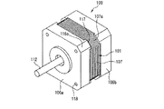
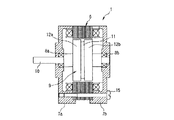
図1〜図3を参照して、このハイブリッド型ステッピングモータ100は、三相6極のステータ101と、該ステータ101の軸方向の両端部にそれぞれ配設された一対の内嵌部材103a,103bと、ステータ101の内周側に挿入されて内嵌部材103a,103bに軸受104a,104bを介して回転可能に支持されたロータ105と、ステータ101の軸方向の両端部にそれぞれ嵌合された一対のブラケット106a,106bとを備える。
【0025】
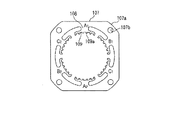
ステータ101は断面略正方形状の外形を有するステータコア107を備えており、ステータコア107の内周部には支柱108と小歯部109からなる6個の磁極A1,B1,C1,A2,B2,C2が周方向に等間隔で設けられている。小歯部109は複数の小歯109aにより構成されており、小歯部109の周方向の中央部に支柱108が配置され、該支柱108に巻線110が巻回されている。
【0026】
また、ステータコア107の外周部の四隅の角部にはそれぞれ円弧状の面取り部107aが形成されており、該面取り部107aの近傍にはステータ101の軸方向に沿って延びるボルト挿通孔107bが形成されている。
【0027】
内嵌部材103a,103bは、ステータ101の内径より若干大径の大径部111と、ステータ101の内径と略同径の小径部(第1の嵌合部)102とを備えた円筒状部材からなっており、小径部102がステータ101の端部内周面に内嵌された状態で該ステータ101の軸方向の両端部にそれぞれ同心に配設されている。
【0028】
また、内嵌部材103a,103bの内周部には、ロータ105の回転軸112を回転可能に支持する軸受104a,104bがそれぞれ圧入等により嵌め込まれている。
【0029】
ロータ105は、回転軸112、該回転軸112に固定された円盤状の永久磁石113及び該永久磁石113の軸方向の両端部に固定された歯車状のロータコア114a,114bによって構成されており、永久磁石113及びロータコア114a,114bが内嵌部材103a,103bの間に位置してステータ101の内周側に50〜100μm程度の極めて小さいエアギャップを介して配設されている。
【0030】
また、ロータコア114aはロータコア114bに対して半ピッチ分だけ周方向にずれており、従って、ロータコア114aの互いに隣り合う歯極(図示せず。)の間にロータコア114bの歯極(図示せず。)が位置するようになっている。
【0031】
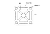
ブラケット106a,106bはステータ101と略同形の外形の有底四角筒状をなしており、底壁の中心部にはロータ105の回転軸112の挿通穴115が形成されている。また、ブラケット106a,106bの外周部の四隅の角部にはそれぞれ面取り部116aがステータ101の面取り部107aに対応して形成されている。
【0032】
ブラケット106a,106bの面取り部116aにはステータ101の面取り部107aに外嵌される嵌合突起(第2の嵌合部)117が該ステータ101の軸方向に沿って延設されており、該嵌合突起117と上述した内嵌部材103a,103bの小径部102とによってステータ101を径方向に挟み込むようになっている。
【0033】
また、ブラケット106aの底壁の四隅にはねじ孔118がステータコア107のボルト挿通孔107bと同心に形成され、ブラケット106bの底壁の四隅にはボルト挿通孔119がボルト挿通孔107bと同心に形成されており、ボルト挿通孔119及び107bに挿入した固定ボルト120をねじ孔118にねじ込むことにより、ステータ101にブラケット106a,106bが固定されるようになっている。
【0034】
かかる固定状態においては、内嵌部材103a,103bの大径部111のステータ101側の端面がステータ101の端面に当接すると共に、内嵌部材103a,103bのステータ101から離間する側の端面の周縁部がブラケット106a,106bの底壁に当接するようになっており、内嵌部材103a,103bとブラケット106a,106bとの当接面にはフッ素樹脂コート(摩擦低減手段)121等が被覆されて両者の間の摩擦低減が図られている。
【0035】
上記の説明から明らかなように、この実施の形態では、ブラケット106a,106bの嵌合突起117と内嵌部材103a,103bの小径部102とによってステータ101を径方向に挟持するようにしているので、軸方向の力の100倍程度ある径方向の加振力によるステータ101の径方向の振動をステータ101の内径側及び外径側の両方から抑制することができ、この結果、騒音や振動を効果的に低減することができる。
【0036】
本実施例のステッピングモータと図7に示す従来構造のステッピングモータとを使用し、ステッピングモータを1020rpmで回転させ、ステッピングモータから10cm離れた位置でステッピングモータから発せられる騒音を測定したところ、次の表1に示す結果が得られた。表1によれば、本実施例の構造を採用することにより、ステッピングモータ単体であれ、ステッピングモータをプリンタの紙送り用として実装した場合であっても、騒音を大幅に低減させることができた。
【0037】
【表1】

また、ブラケット106a,106bと内嵌部材103a,103bとを別体に形成してブラケット106a,106bの内嵌部材103a,103bに対する径方向の位置関係を拘束しないようにしているので、ステータ101の外径に対するブラケット106a,106bの位置決めと、ステータ101の内径に対する内嵌部材103a,103bの位置決めとをそれぞれ独立して行うことができ、この結果、ステータ101と内嵌部材103a,103b、又はステータ101とブラケット106a,106bの各々の挟持を高精度に行うことが可能となってステータ101の径方向の挟持を内周面及び外周面の両方から確実に行うことができる。
【0039】
更に、内嵌部材103a,103bとブラケット106a,106bとの当接面にフッ素樹脂コート121等を被覆して両者の間の摩擦低減を図るようにしているので、ブラケット106a,106bを組付ける際に、ブラケット106a,106bを内嵌部材103a,103bに対して滑らせることができ、この結果、内嵌部材103a,103bによるブラケット106a,106bの拘束を避けられ、ブラケット106a,106bの組付け性の容易化とステータ101の内側及び外側からの挟持位置決めの独立性の保持とを図ることができる。
【0040】
更に、ロータ105の回転軸112を支持する軸受104a,104bをステータ101の内径に嵌合された内嵌部材103a,103bによって直接保持するようにしているので、軸受104a,104bをブラケット106a,106bで保持する場合に比べて、ステータ101の内径とロータ105の回転軸112との同軸度を向上させることができ、この結果、ロータ105とステータ101との間のエアギャップの均一化を図ることができる。
【0041】
なお、上記実施の形態では、内嵌部材103a,103bとブラケット106a,106bとの当接面の摩擦を低減する手段として、フッ素樹脂コート121を例に採ったが、これに限定されず、該当接面の接触面積を小さくするような表面加工を施して摩擦を低減するようにしてもよい。
【0042】
また、摩擦低減手段に代えて又は摩擦低減手段に加えて、内嵌部材103a,103bとブラケット106a,106bとの当接面に弾性部材や低反発性ゴム等の振動吸収部材(図示せず。)を介在させるようにしてもよい。
【0043】
このようにすると、内嵌部材103a,103b側の振動とブラケット106a,106b側の振動とが互いに干渉しないようにすることができるので、騒音・振動をより効果的に低減することができ、また、振動吸収部材の弾性に固定ボルト120の弛み止めとしての機能を持たせることができる。
【0044】
更に、上記実施の形態では、三相6極のステータ101を備えたハイブリッド型ステッピングモータを例に採ったが、これに代えて、例えば図4に示すように、二相8極のステータを備えたハイブリッド型ステッピングモータに本発明を適用してもよいのは勿論であり、更に、相数、極数の如何を問わず、ハイブリッド型ステッピングモータ一般に本発明を適用してもよい。
【0045】
図4に示すステータのステータコア200は固定ボルト120のボルト挿通穴107bが全て磁極B1,B2,B3,B4の支柱108の径方向の延長線上に配置されているため、支柱108から伝達される径方向の振動を固定ボルト120の締め付け位置で抑制することができ、この結果、騒音・振動の低減効果のより向上を図ることができる。
【0046】
更に、図5に示すように、ブラケット106a,106bの四隅の嵌合突起117を対角線状にリブ201でつなぐようにしたり、或いは図6に示すように、ブラケット106a,106bの四隅の嵌合突起117を対角線状にリブ202でつなぐと共に四隅の嵌合突起117を周方向にリブ203でつなぐことにより、各嵌合突起117の剛性が増して、ブラケット106a,106bの嵌合突起117と内嵌部材103a,103bの小径部102とによるステータ101の径方向の挟持をより確実なものとすることができる。
【0047】
【発明の効果】
上記の説明から明らかなように、本発明によれば、ステータとロータとの間の半径方向の加振力によるステータの径方向の振動を抑えることにより騒音や振動を確実且つ効果的に低減することができるステッピングモータを提供することができるという効果が得られる。
【図面の簡単な説明】
【図1】本発明の実施の形態の一例であるハイブリッド型ステッピングモータを説明するための説明的斜視図である。
【図2】該ハイブリッド型ステッピングモータの断面図である。
【図3】ステータコアを示す軸方向から見た平面図である。
【図4】ステータコアの変形例を示す軸方向から見た平面図である。
【図5】ブラケット対の変形例を示す平面図である。
【図6】ブラケット対の他の変形例を示す平面図である。
【図7】従来のハイブリッド型ステッピングモータの断面図である。
【符号の説明】
100…ハイブリッド型ステッピングモータ
101…ステータ
102…小径部(第1の嵌合部)
103a,103b…内嵌部材
104a,104b…軸受
105…ロータ
106a,106b…ブラケット
107…ステータコア
108…支柱
109…小歯部
110…巻線
112…回転軸
113…永久磁石
114a,114b…ロータコア
117…嵌合突起(第2の嵌合部)
120…固定ボルト
121…フッ素樹脂コート(摩擦低減手段)
201,202,203…リブ[0001]
BACKGROUND OF THE INVENTION
The present invention relates to a stepping motor, and more particularly to a hybrid type stepping motor used for an ink jet printer, a scanner, or the like.
[0002]
[Prior art]
As a conventional hybrid type stepping motor of this type, for example, the one shown in FIG. 7 is known.
[0003]
The stepping motor 1 includes a three-phase six-pole stator 6, a pair of
[0004]
The
[0005]
The
[0006]
[Problems to be solved by the invention]
By the way, although it is well known that the hybrid type stepping motor is a motor that generates a lot of noise and a lot of vibrations, a technology for effectively reducing such noises and vibrations has not been proposed yet. .
[0007]
Therefore, as a result of analysis of the cause of noise and vibration of the hybrid type stepping motor by the present inventors, the radius between the stator 6 and the
[0008]
The present invention has been made based on such knowledge, and it is possible to reliably and effectively reduce noise and vibration by suppressing radial vibration of the stator due to radial excitation force between the stator and the rotor. An object of the present invention is to provide a stepping motor capable of performing
[0009]
[Means for Solving the Problems]
In order to achieve such an object, a stepping motor according to a first aspect of the present invention includes a stator core in which a plurality of magnetic poles each including a support and a small tooth portion are provided at predetermined intervals in the circumferential direction, and a winding around the magnetic pole. A stator having a wound winding;
A rotor inserted into the inner peripheral side of the stator and rotatably supported through a bearing;
A stepping motor comprising a pair of brackets respectively fitted to both axial ends of the stator,
A pair of inner fitting members disposed at both ends of the stator in the axial direction and having a first fitting portion fitted into an inner circumferential surface of the end of the stator, the first of the inner fitting members; Each of the pair of brackets and a second fitting portion that is externally fitted to the outer peripheral surface of the axial end portion of the stator, and the stator is sandwiched in the radial direction, and the inner The fitting member and the bracket are formed separately so that the radial positional relationship of the bracket with respect to the inner fitting member is not restricted.
[0010]
According to this means, the vibration in the radial direction of the stator due to the radial excitation force that is about 100 times the axial force can be suppressed from both the inner diameter side and the outer diameter side of the stator. Can be effectively reduced.
[0011]
In addition, since the positioning of the bracket with respect to the outer diameter of the stator and the positioning of the inner fitting member with respect to the inner diameter of the stator can be performed independently, the stator and the inner fitting member or the stator and the bracket can be clamped with high accuracy. Therefore, the stator can be securely clamped from both the inner and outer peripheral surfaces.
[0012]
A stepping motor according to a second aspect is characterized in that, in the first aspect, a friction reducing means for reducing friction between the bracket and the inner fitting member is provided on the axial contact surface.
[0013]
According to this means, when the bracket is assembled, the bracket can be slid with respect to the inner fitting member, so that the bracket is not restrained by the inner fitting member, the ease of assembling of the bracket and the stator can be reduced. It is possible to maintain the independence of the clamping positioning from the inner side and the outer side.
[0014]
A stepping motor according to a third aspect of the present invention is the stepping motor according to the first or second aspect, wherein a vibration absorbing member is interposed on an axial contact surface between the bracket and the inner fitting member.
[0015]
According to this means, the vibration on the inner fitting member side and the vibration on the bracket side can be prevented from interfering with each other, so that noise and vibration can be reduced more effectively.
[0016]
A stepping motor according to a fourth aspect of the present invention is the stepping motor according to any one of the first to third aspects, wherein the bracket pair is fixed to the stator with a bolt on a radial extension line of the magnetic pole column of the stator. .
[0017]
According to this means, since the vibration in the radial direction transmitted from the support can be suppressed at the bolt tightening position, the effect of reducing noise and vibration can be further improved.
[0018]
A stepping motor according to a fifth aspect of the present invention is the stepping motor according to any one of the first to fourth aspects, wherein the bearing is attached to the inner fitting member.
[0019]
According to this means, the coaxiality between the inner diameter of the stator and the rotor can be improved as compared with the case where the bearing is held by the bracket, so that the air gap between the rotor and the stator can be made uniform. it can.
[0020]
A stepping motor according to a sixth aspect is characterized in that, in any one of the first to fifth aspects, a rib for reinforcing the second fitting portion is provided in the bracket pair.
[0021]
According to this means, the rigidity of the second fitting portion of the bracket is increased, and the stator can be more securely held in the radial direction by the second fitting portion and the first fitting portion of the inner fitting member. Can be.
[0022]
DETAILED DESCRIPTION OF THE INVENTION
Hereinafter, embodiments of the present invention will be described with reference to the drawings.
[0023]
FIG. 1 is an explanatory perspective view for explaining a hybrid stepping motor as an example of an embodiment of the present invention, FIG. 2 is a sectional view of the hybrid stepping motor, and FIG. 3 is an axial view showing a stator core. FIG. 4 is a plan view seen from the axial direction showing a modified example of the stator core, and FIGS. 5 and 6 are plan views showing modified examples of the bracket pair.
[0024]
1 to 3, a
[0025]
The
[0026]
Further, arcuate
[0027]
The inner
[0028]
In addition,
[0029]
The
[0030]
Further, the
[0031]
The
[0032]
The
[0033]
Also, screw
[0034]
In such a fixed state, the end surfaces on the
[0035]
As is clear from the above description, in this embodiment, the
[0036]
Using the stepping motor of this example and the stepping motor having the conventional structure shown in FIG. 7, the stepping motor was rotated at 1020 rpm, and the noise emitted from the stepping motor was measured at a
[0037]
[Table 1]
Further, the
[0039]
Further, since the contact surface between the
[0040]
Further, since the
[0041]
In the above embodiment, the
[0042]
Further, instead of the friction reducing means or in addition to the friction reducing means, a vibration absorbing member (not shown) such as an elastic member or low resilience rubber is provided on the contact surface between the
[0043]
In this way, the vibration on the
[0044]
Further, in the above embodiment, the hybrid stepping motor including the three-phase six-
[0045]
In the
[0046]
Further, as shown in FIG. 5, the
[0047]
【The invention's effect】
As is apparent from the above description, according to the present invention, noise and vibration can be reliably and effectively reduced by suppressing radial vibration of the stator due to radial excitation force between the stator and the rotor. The effect that the stepping motor which can be provided can be provided is acquired.
[Brief description of the drawings]
FIG. 1 is an explanatory perspective view for explaining a hybrid stepping motor which is an example of an embodiment of the present invention.
FIG. 2 is a sectional view of the hybrid stepping motor.
FIG. 3 is a plan view of the stator core as seen from the axial direction.
FIG. 4 is a plan view seen from an axial direction showing a modified example of a stator core.
FIG. 5 is a plan view showing a modification of the bracket pair.
FIG. 6 is a plan view showing another modification of the bracket pair.
FIG. 7 is a cross-sectional view of a conventional hybrid type stepping motor.
[Explanation of symbols]
DESCRIPTION OF
103a, 103b ...
120 ... Fixing
201, 202, 203 ... ribs
Claims (6)
該ステータの内周側に挿入されて軸受を介して回転可能に支持されたロータと、
前記ステータの軸方向の両端部にそれぞれ嵌合された一対のブラケットとを備えたステッピングモータであって、
前記ステータの軸方向の両端部にそれぞれ配設され、該ステータの端部内周面に内嵌される第1の嵌合部を有する一対の内嵌部材を備え、該内嵌部材の前記第1の嵌合部と、前記一対のブラケットにそれぞれ設けられて前記ステータの軸方向の端部外周面に外嵌される第2の嵌合部とによって前記ステータを径方向に挟み込み、且つ、前記内嵌部材と前記ブラケットとを別体に形成して該ブラケットの前記内嵌部材に対する径方向の位置関係を拘束しないようにしたことを特徴とするステッピングモータ。A stator core provided with a plurality of magnetic poles composed of support pillars and small teeth on the inner periphery at predetermined intervals in the circumferential direction, and a stator comprising a winding wound around the magnetic poles;
A rotor inserted into the inner peripheral side of the stator and rotatably supported via a bearing;
A stepping motor comprising a pair of brackets respectively fitted to both axial ends of the stator,
A pair of inner fitting members disposed at both ends in the axial direction of the stator and having a first fitting portion fitted into an inner peripheral surface of the end of the stator, the first of the inner fitting members; The stator is radially sandwiched between the fitting portion and a second fitting portion that is provided on each of the pair of brackets and is fitted on the outer peripheral surface of the axial end portion of the stator, and the inner A stepping motor, wherein the fitting member and the bracket are formed separately so as not to restrain the radial positional relationship of the bracket with respect to the inner fitting member.
Priority Applications (6)
| Application Number | Priority Date | Filing Date | Title |
|---|---|---|---|
| JP00108599A JP3736166B2 (en) | 1999-01-06 | 1999-01-06 | Stepping motor |
| SG9905649A SG85149A1 (en) | 1999-01-06 | 1999-11-12 | Stepping motor |
| DE69912234T DE69912234T2 (en) | 1999-01-06 | 1999-12-14 | stepper motor |
| EP99124915A EP1018796B1 (en) | 1999-01-06 | 1999-12-14 | Stepping motor |
| US09/468,484 US6249066B1 (en) | 1999-01-06 | 1999-12-16 | Stepping motor |
| CNB001009079A CN1135678C (en) | 1999-01-06 | 2000-01-05 | Stepping motor |
Applications Claiming Priority (1)
| Application Number | Priority Date | Filing Date | Title |
|---|---|---|---|
| JP00108599A JP3736166B2 (en) | 1999-01-06 | 1999-01-06 | Stepping motor |
Publications (2)
| Publication Number | Publication Date |
|---|---|
| JP2000201468A JP2000201468A (en) | 2000-07-18 |
| JP3736166B2 true JP3736166B2 (en) | 2006-01-18 |
Family
ID=11491675
Family Applications (1)
| Application Number | Title | Priority Date | Filing Date |
|---|---|---|---|
| JP00108599A Expired - Fee Related JP3736166B2 (en) | 1999-01-06 | 1999-01-06 | Stepping motor |
Country Status (6)
| Country | Link |
|---|---|
| US (1) | US6249066B1 (en) |
| EP (1) | EP1018796B1 (en) |
| JP (1) | JP3736166B2 (en) |
| CN (1) | CN1135678C (en) |
| DE (1) | DE69912234T2 (en) |
| SG (1) | SG85149A1 (en) |
Families Citing this family (27)
| Publication number | Priority date | Publication date | Assignee | Title |
|---|---|---|---|---|
| JP2990432B1 (en) * | 1998-05-12 | 1999-12-13 | ミネベア株式会社 | Stepping motor |
| JP4744023B2 (en) * | 2001-07-24 | 2011-08-10 | 日本電産サーボ株式会社 | Permanent magnet 3-phase stepping motor |
| JP3944825B2 (en) * | 2001-11-16 | 2007-07-18 | ミネベア株式会社 | Sealed structure motor and method of using the same |
| JP4038664B2 (en) * | 2002-06-05 | 2008-01-30 | ミネベア株式会社 | Stepping motor |
| DE10312614A1 (en) * | 2003-03-21 | 2004-10-14 | Robert Bosch Gmbh | Electrical machine with rotor bearing integrated in the stator |
| JP2005033860A (en) * | 2003-07-08 | 2005-02-03 | Minebea Co Ltd | Structure of claw-pole stepping motor |
| JP2008278550A (en) * | 2007-04-25 | 2008-11-13 | Japan Servo Co Ltd | Vibration isolation motor |
| JP5134935B2 (en) * | 2007-12-07 | 2013-01-30 | 株式会社日立産機システム | Electric motor |
| JP5171310B2 (en) * | 2008-02-25 | 2013-03-27 | 山洋電気株式会社 | Airtight motor |
| US7755229B2 (en) * | 2008-08-09 | 2010-07-13 | Hiwin Mikrosystem Corp. | Hybrid step motor |
| DE102009024991B4 (en) | 2009-06-16 | 2022-01-13 | Vorwerk & Co. Interholding Gmbh | Electric motor and method for assembling an electric motor |
| US8278803B2 (en) * | 2009-08-14 | 2012-10-02 | Lin Engineering | Motor end cap positioning element for maintaining rotor-stator concentricity |
| EP2395638A3 (en) * | 2010-06-11 | 2017-04-12 | Nidec Servo Corporation | Rotary electric machine |
| US8283841B2 (en) * | 2010-06-23 | 2012-10-09 | Lin Engineering | Motor end cap with interference fit |
| JP5969241B2 (en) * | 2012-03-29 | 2016-08-17 | 株式会社デンソー | Drive device |
| CN102780366A (en) * | 2012-07-23 | 2012-11-14 | 苏州德能电机有限公司 | Novel three-phase asynchronous motor |
| US20140125191A1 (en) * | 2012-11-07 | 2014-05-08 | Lin Engineering | Vibration dampening structure for stepper motors |
| CN103915970B (en) * | 2013-01-09 | 2016-03-16 | 上海鸣志电器股份有限公司 | Composite stepper motor |
| JP6469954B2 (en) * | 2014-03-07 | 2019-02-13 | オリエンタルモーター株式会社 | Hybrid stepping motor |
| CN105546010B (en) * | 2016-01-22 | 2017-06-27 | 山东理工大学 | Three-phase electric excitation biconvex electrode telescopic shock absorber |
| CN108886292A (en) * | 2016-03-31 | 2018-11-23 | 日本电产株式会社 | Motor |
| CN106208454A (en) * | 2016-08-29 | 2016-12-07 | 贵州航天林泉电机有限公司 | A kind of extra small air gap micro-step motor |
| JP6523372B2 (en) * | 2017-06-01 | 2019-05-29 | ファナック株式会社 | Electric motor with housing integrated with stator |
| CN109391076A (en) * | 2017-08-08 | 2019-02-26 | 索恩格汽车部件(中国)有限公司 | Motor |
| JP7264717B2 (en) * | 2019-05-15 | 2023-04-25 | ファナック株式会社 | Electric motor with a housing fixed to the end face of the stator core |
| EP3835528A1 (en) * | 2019-12-09 | 2021-06-16 | dormakaba Deutschland GmbH | Door drive with a motor unit having a beneficial basic design |
| FR3121555A1 (en) * | 2021-04-06 | 2022-10-07 | Inteva Products, Llc. | STATOR FOR BRUSHLESS MOTOR OR GENERATOR |
Family Cites Families (13)
| Publication number | Priority date | Publication date | Assignee | Title |
|---|---|---|---|---|
| JPS59135087U (en) * | 1983-02-26 | 1984-09-10 | シナノケンシ株式会社 | Permanent magnet step motor |
| JPS6091852A (en) * | 1983-10-20 | 1985-05-23 | Ricoh Elemex Corp | Rotary motor |
| JP2598107B2 (en) * | 1988-10-07 | 1997-04-09 | ファナック株式会社 | Motor bearing structure |
| CA2011025A1 (en) | 1989-03-01 | 1990-09-01 | Terry R. Beardsley | Feline infectious peritonitis vaccine |
| JP3041034B2 (en) | 1990-10-20 | 2000-05-15 | マツダ株式会社 | Liquid-filled engine mount |
| JP3071064B2 (en) * | 1992-04-20 | 2000-07-31 | 日本サーボ株式会社 | Permanent magnet type stepping motor |
| GB2283133B (en) * | 1993-10-20 | 1998-04-15 | Gen Electric | Dynamoelectric machine and method for manufacturing same |
| JPH08298739A (en) * | 1995-04-25 | 1996-11-12 | Minebea Co Ltd | Stepping motor |
| JP3054582B2 (en) | 1995-05-29 | 2000-06-19 | 三洋電機株式会社 | Destination selection method and destination selection device in FM multiplex broadcast receiver |
| JPH1054582A (en) | 1996-08-12 | 1998-02-24 | Corona Corp | Air conditioner |
| JP3399499B2 (en) * | 1997-04-18 | 2003-04-21 | セイコーエプソン株式会社 | Stepping motor |
| US6057613A (en) * | 1998-02-04 | 2000-05-02 | Pacific Scientific Company | Hybrid stepper motor having optimized torque density |
| JP2990432B1 (en) * | 1998-05-12 | 1999-12-13 | ミネベア株式会社 | Stepping motor |
-
1999
- 1999-01-06 JP JP00108599A patent/JP3736166B2/en not_active Expired - Fee Related
- 1999-11-12 SG SG9905649A patent/SG85149A1/en unknown
- 1999-12-14 DE DE69912234T patent/DE69912234T2/en not_active Expired - Lifetime
- 1999-12-14 EP EP99124915A patent/EP1018796B1/en not_active Expired - Lifetime
- 1999-12-16 US US09/468,484 patent/US6249066B1/en not_active Expired - Lifetime
-
2000
- 2000-01-05 CN CNB001009079A patent/CN1135678C/en not_active Expired - Fee Related
Also Published As
| Publication number | Publication date |
|---|---|
| EP1018796A2 (en) | 2000-07-12 |
| EP1018796A3 (en) | 2001-03-28 |
| US6249066B1 (en) | 2001-06-19 |
| CN1135678C (en) | 2004-01-21 |
| CN1259790A (en) | 2000-07-12 |
| DE69912234T2 (en) | 2004-08-05 |
| DE69912234D1 (en) | 2003-11-27 |
| SG85149A1 (en) | 2001-12-19 |
| JP2000201468A (en) | 2000-07-18 |
| EP1018796B1 (en) | 2003-10-22 |
Similar Documents
| Publication | Publication Date | Title |
|---|---|---|
| JP3736166B2 (en) | Stepping motor | |
| JP2007049844A (en) | Outer-rotor motor | |
| US20040207280A1 (en) | Brushless DC motor with stepped skewed rotor | |
| US20080030093A1 (en) | Permanent magnetic synchronous electrical motor | |
| US8896190B2 (en) | Electric apparatus with stator core | |
| JP5138489B2 (en) | Resolver rotor fixing structure and brushless motor | |
| JP3364960B2 (en) | Permanent magnet motor rotor | |
| US20180262081A1 (en) | Electric motor including stator assembly and method of assembly thereof | |
| JP2010035375A (en) | Motor | |
| JP2002101583A (en) | Electric motor | |
| JP2004023937A (en) | Bracket and stepping motor | |
| JP2573894Y2 (en) | PM type stepping motor | |
| JP5621608B2 (en) | Outer rotor type motor | |
| JP2009183058A (en) | Method for securing stator core, and brushless motor | |
| JP2005198440A (en) | Motor | |
| JP3054582U (en) | Stepping motor | |
| JP2000197335A (en) | Stepping motor | |
| JP3041034U (en) | Laminated core inner rotor type rotating electric machine | |
| JP2003009499A (en) | Motor structure of claw pole type stepping motor | |
| JP2005278333A (en) | Permanent magnet type motor | |
| JP5363054B2 (en) | motor | |
| KR100256785B1 (en) | Permanent magnetic electromotor | |
| JP3615394B2 (en) | motor | |
| JPH051964Y2 (en) | ||
| JP3598677B2 (en) | Stepping motor |
Legal Events
| Date | Code | Title | Description |
|---|---|---|---|
| A977 | Report on retrieval |
Free format text: JAPANESE INTERMEDIATE CODE: A971007 Effective date: 20050114 |
|
| A131 | Notification of reasons for refusal |
Free format text: JAPANESE INTERMEDIATE CODE: A131 Effective date: 20050125 |
|
| RD03 | Notification of appointment of power of attorney |
Free format text: JAPANESE INTERMEDIATE CODE: A7423 Effective date: 20050315 |
|
| TRDD | Decision of grant or rejection written | ||
| A01 | Written decision to grant a patent or to grant a registration (utility model) |
Free format text: JAPANESE INTERMEDIATE CODE: A01 Effective date: 20051004 |
|
| A61 | First payment of annual fees (during grant procedure) |
Free format text: JAPANESE INTERMEDIATE CODE: A61 Effective date: 20051017 |
|
| R150 | Certificate of patent or registration of utility model |
Free format text: JAPANESE INTERMEDIATE CODE: R150 |
|
| FPAY | Renewal fee payment (event date is renewal date of database) |
Free format text: PAYMENT UNTIL: 20091104 Year of fee payment: 4 |
|
| FPAY | Renewal fee payment (event date is renewal date of database) |
Free format text: PAYMENT UNTIL: 20091104 Year of fee payment: 4 |
|
| FPAY | Renewal fee payment (event date is renewal date of database) |
Free format text: PAYMENT UNTIL: 20101104 Year of fee payment: 5 |
|
| FPAY | Renewal fee payment (event date is renewal date of database) |
Free format text: PAYMENT UNTIL: 20101104 Year of fee payment: 5 |
|
| FPAY | Renewal fee payment (event date is renewal date of database) |
Free format text: PAYMENT UNTIL: 20111104 Year of fee payment: 6 |
|
| FPAY | Renewal fee payment (event date is renewal date of database) |
Free format text: PAYMENT UNTIL: 20111104 Year of fee payment: 6 |
|
| FPAY | Renewal fee payment (event date is renewal date of database) |
Free format text: PAYMENT UNTIL: 20121104 Year of fee payment: 7 |
|
| FPAY | Renewal fee payment (event date is renewal date of database) |
Free format text: PAYMENT UNTIL: 20121104 Year of fee payment: 7 |
|
| FPAY | Renewal fee payment (event date is renewal date of database) |
Free format text: PAYMENT UNTIL: 20131104 Year of fee payment: 8 |
|
| LAPS | Cancellation because of no payment of annual fees |