JP3732459B2 - Display element forming method - Google Patents
Display element forming method Download PDFInfo
- Publication number
- JP3732459B2 JP3732459B2 JP2002157699A JP2002157699A JP3732459B2 JP 3732459 B2 JP3732459 B2 JP 3732459B2 JP 2002157699 A JP2002157699 A JP 2002157699A JP 2002157699 A JP2002157699 A JP 2002157699A JP 3732459 B2 JP3732459 B2 JP 3732459B2
- Authority
- JP
- Japan
- Prior art keywords
- web
- sheet
- composite
- display element
- nonwoven fabric
- Prior art date
- Legal status (The legal status is an assumption and is not a legal conclusion. Google has not performed a legal analysis and makes no representation as to the accuracy of the status listed.)
- Expired - Fee Related
Links
Images


Classifications
-
- A—HUMAN NECESSITIES
- A61—MEDICAL OR VETERINARY SCIENCE; HYGIENE
- A61F—FILTERS IMPLANTABLE INTO BLOOD VESSELS; PROSTHESES; DEVICES PROVIDING PATENCY TO, OR PREVENTING COLLAPSING OF, TUBULAR STRUCTURES OF THE BODY, e.g. STENTS; ORTHOPAEDIC, NURSING OR CONTRACEPTIVE DEVICES; FOMENTATION; TREATMENT OR PROTECTION OF EYES OR EARS; BANDAGES, DRESSINGS OR ABSORBENT PADS; FIRST-AID KITS
- A61F13/00—Bandages or dressings; Absorbent pads
- A61F13/15—Absorbent pads, e.g. sanitary towels, swabs or tampons for external or internal application to the body; Supporting or fastening means therefor; Tampon applicators
- A61F13/15577—Apparatus or processes for manufacturing
- A61F13/15707—Mechanical treatment, e.g. notching, twisting, compressing, shaping
- A61F13/15723—Partitioning batts; Cutting
-
- A—HUMAN NECESSITIES
- A61—MEDICAL OR VETERINARY SCIENCE; HYGIENE
- A61F—FILTERS IMPLANTABLE INTO BLOOD VESSELS; PROSTHESES; DEVICES PROVIDING PATENCY TO, OR PREVENTING COLLAPSING OF, TUBULAR STRUCTURES OF THE BODY, e.g. STENTS; ORTHOPAEDIC, NURSING OR CONTRACEPTIVE DEVICES; FOMENTATION; TREATMENT OR PROTECTION OF EYES OR EARS; BANDAGES, DRESSINGS OR ABSORBENT PADS; FIRST-AID KITS
- A61F13/00—Bandages or dressings; Absorbent pads
- A61F13/15—Absorbent pads, e.g. sanitary towels, swabs or tampons for external or internal application to the body; Supporting or fastening means therefor; Tampon applicators
- A61F13/15577—Apparatus or processes for manufacturing
- A61F13/15699—Forming webs by bringing together several webs, e.g. by laminating or folding several webs, with or without additional treatment of the webs
-
- A—HUMAN NECESSITIES
- A61—MEDICAL OR VETERINARY SCIENCE; HYGIENE
- A61F—FILTERS IMPLANTABLE INTO BLOOD VESSELS; PROSTHESES; DEVICES PROVIDING PATENCY TO, OR PREVENTING COLLAPSING OF, TUBULAR STRUCTURES OF THE BODY, e.g. STENTS; ORTHOPAEDIC, NURSING OR CONTRACEPTIVE DEVICES; FOMENTATION; TREATMENT OR PROTECTION OF EYES OR EARS; BANDAGES, DRESSINGS OR ABSORBENT PADS; FIRST-AID KITS
- A61F13/00—Bandages or dressings; Absorbent pads
- A61F13/15—Absorbent pads, e.g. sanitary towels, swabs or tampons for external or internal application to the body; Supporting or fastening means therefor; Tampon applicators
- A61F13/15577—Apparatus or processes for manufacturing
- A61F13/15756—Applying tabs, strips, tapes, loops; Knotting the ends of pads
-
- A—HUMAN NECESSITIES
- A61—MEDICAL OR VETERINARY SCIENCE; HYGIENE
- A61F—FILTERS IMPLANTABLE INTO BLOOD VESSELS; PROSTHESES; DEVICES PROVIDING PATENCY TO, OR PREVENTING COLLAPSING OF, TUBULAR STRUCTURES OF THE BODY, e.g. STENTS; ORTHOPAEDIC, NURSING OR CONTRACEPTIVE DEVICES; FOMENTATION; TREATMENT OR PROTECTION OF EYES OR EARS; BANDAGES, DRESSINGS OR ABSORBENT PADS; FIRST-AID KITS
- A61F13/00—Bandages or dressings; Absorbent pads
- A61F13/15—Absorbent pads, e.g. sanitary towels, swabs or tampons for external or internal application to the body; Supporting or fastening means therefor; Tampon applicators
- A61F13/15577—Apparatus or processes for manufacturing
- A61F13/15804—Plant, e.g. involving several steps
-
- A—HUMAN NECESSITIES
- A61—MEDICAL OR VETERINARY SCIENCE; HYGIENE
- A61F—FILTERS IMPLANTABLE INTO BLOOD VESSELS; PROSTHESES; DEVICES PROVIDING PATENCY TO, OR PREVENTING COLLAPSING OF, TUBULAR STRUCTURES OF THE BODY, e.g. STENTS; ORTHOPAEDIC, NURSING OR CONTRACEPTIVE DEVICES; FOMENTATION; TREATMENT OR PROTECTION OF EYES OR EARS; BANDAGES, DRESSINGS OR ABSORBENT PADS; FIRST-AID KITS
- A61F13/00—Bandages or dressings; Absorbent pads
- A61F13/15—Absorbent pads, e.g. sanitary towels, swabs or tampons for external or internal application to the body; Supporting or fastening means therefor; Tampon applicators
- A61F13/45—Absorbent pads, e.g. sanitary towels, swabs or tampons for external or internal application to the body; Supporting or fastening means therefor; Tampon applicators characterised by the shape
- A61F13/49—Absorbent articles specially adapted to be worn around the waist, e.g. diapers
- A61F13/496—Absorbent articles specially adapted to be worn around the waist, e.g. diapers in the form of pants or briefs
-
- A—HUMAN NECESSITIES
- A61—MEDICAL OR VETERINARY SCIENCE; HYGIENE
- A61F—FILTERS IMPLANTABLE INTO BLOOD VESSELS; PROSTHESES; DEVICES PROVIDING PATENCY TO, OR PREVENTING COLLAPSING OF, TUBULAR STRUCTURES OF THE BODY, e.g. STENTS; ORTHOPAEDIC, NURSING OR CONTRACEPTIVE DEVICES; FOMENTATION; TREATMENT OR PROTECTION OF EYES OR EARS; BANDAGES, DRESSINGS OR ABSORBENT PADS; FIRST-AID KITS
- A61F13/00—Bandages or dressings; Absorbent pads
- A61F13/15—Absorbent pads, e.g. sanitary towels, swabs or tampons for external or internal application to the body; Supporting or fastening means therefor; Tampon applicators
- A61F13/15203—Properties of the article, e.g. stiffness or absorbency
- A61F2013/15243—Properties of the article, e.g. stiffness or absorbency printed or coloured, e.g. to match skin
-
- A—HUMAN NECESSITIES
- A61—MEDICAL OR VETERINARY SCIENCE; HYGIENE
- A61F—FILTERS IMPLANTABLE INTO BLOOD VESSELS; PROSTHESES; DEVICES PROVIDING PATENCY TO, OR PREVENTING COLLAPSING OF, TUBULAR STRUCTURES OF THE BODY, e.g. STENTS; ORTHOPAEDIC, NURSING OR CONTRACEPTIVE DEVICES; FOMENTATION; TREATMENT OR PROTECTION OF EYES OR EARS; BANDAGES, DRESSINGS OR ABSORBENT PADS; FIRST-AID KITS
- A61F13/00—Bandages or dressings; Absorbent pads
- A61F13/15—Absorbent pads, e.g. sanitary towels, swabs or tampons for external or internal application to the body; Supporting or fastening means therefor; Tampon applicators
- A61F13/45—Absorbent pads, e.g. sanitary towels, swabs or tampons for external or internal application to the body; Supporting or fastening means therefor; Tampon applicators characterised by the shape
- A61F13/49—Absorbent articles specially adapted to be worn around the waist, e.g. diapers
- A61F13/49058—Absorbent articles specially adapted to be worn around the waist, e.g. diapers characterised by the modular concept of constructing the diaper
- A61F2013/49063—Absorbent articles specially adapted to be worn around the waist, e.g. diapers characterised by the modular concept of constructing the diaper the diaper having decoupled components
-
- A—HUMAN NECESSITIES
- A61—MEDICAL OR VETERINARY SCIENCE; HYGIENE
- A61F—FILTERS IMPLANTABLE INTO BLOOD VESSELS; PROSTHESES; DEVICES PROVIDING PATENCY TO, OR PREVENTING COLLAPSING OF, TUBULAR STRUCTURES OF THE BODY, e.g. STENTS; ORTHOPAEDIC, NURSING OR CONTRACEPTIVE DEVICES; FOMENTATION; TREATMENT OR PROTECTION OF EYES OR EARS; BANDAGES, DRESSINGS OR ABSORBENT PADS; FIRST-AID KITS
- A61F13/00—Bandages or dressings; Absorbent pads
- A61F13/15—Absorbent pads, e.g. sanitary towels, swabs or tampons for external or internal application to the body; Supporting or fastening means therefor; Tampon applicators
- A61F13/84—Accessories, not otherwise provided for, for absorbent pads
- A61F2013/8497—Accessories, not otherwise provided for, for absorbent pads having decorations or indicia means
-
- Y—GENERAL TAGGING OF NEW TECHNOLOGICAL DEVELOPMENTS; GENERAL TAGGING OF CROSS-SECTIONAL TECHNOLOGIES SPANNING OVER SEVERAL SECTIONS OF THE IPC; TECHNICAL SUBJECTS COVERED BY FORMER USPC CROSS-REFERENCE ART COLLECTIONS [XRACs] AND DIGESTS
- Y10—TECHNICAL SUBJECTS COVERED BY FORMER USPC
- Y10T—TECHNICAL SUBJECTS COVERED BY FORMER US CLASSIFICATION
- Y10T156/00—Adhesive bonding and miscellaneous chemical manufacture
- Y10T156/10—Methods of surface bonding and/or assembly therefor
- Y10T156/1002—Methods of surface bonding and/or assembly therefor with permanent bending or reshaping or surface deformation of self sustaining lamina
- Y10T156/1043—Subsequent to assembly
- Y10T156/1049—Folding only
-
- Y—GENERAL TAGGING OF NEW TECHNOLOGICAL DEVELOPMENTS; GENERAL TAGGING OF CROSS-SECTIONAL TECHNOLOGIES SPANNING OVER SEVERAL SECTIONS OF THE IPC; TECHNICAL SUBJECTS COVERED BY FORMER USPC CROSS-REFERENCE ART COLLECTIONS [XRACs] AND DIGESTS
- Y10—TECHNICAL SUBJECTS COVERED BY FORMER USPC
- Y10T—TECHNICAL SUBJECTS COVERED BY FORMER US CLASSIFICATION
- Y10T156/00—Adhesive bonding and miscellaneous chemical manufacture
- Y10T156/10—Methods of surface bonding and/or assembly therefor
- Y10T156/1002—Methods of surface bonding and/or assembly therefor with permanent bending or reshaping or surface deformation of self sustaining lamina
- Y10T156/1051—Methods of surface bonding and/or assembly therefor with permanent bending or reshaping or surface deformation of self sustaining lamina by folding
-
- Y—GENERAL TAGGING OF NEW TECHNOLOGICAL DEVELOPMENTS; GENERAL TAGGING OF CROSS-SECTIONAL TECHNOLOGIES SPANNING OVER SEVERAL SECTIONS OF THE IPC; TECHNICAL SUBJECTS COVERED BY FORMER USPC CROSS-REFERENCE ART COLLECTIONS [XRACs] AND DIGESTS
- Y10—TECHNICAL SUBJECTS COVERED BY FORMER USPC
- Y10T—TECHNICAL SUBJECTS COVERED BY FORMER US CLASSIFICATION
- Y10T156/00—Adhesive bonding and miscellaneous chemical manufacture
- Y10T156/10—Methods of surface bonding and/or assembly therefor
- Y10T156/1052—Methods of surface bonding and/or assembly therefor with cutting, punching, tearing or severing
- Y10T156/1062—Prior to assembly
- Y10T156/1067—Continuous longitudinal slitting
-
- Y—GENERAL TAGGING OF NEW TECHNOLOGICAL DEVELOPMENTS; GENERAL TAGGING OF CROSS-SECTIONAL TECHNOLOGIES SPANNING OVER SEVERAL SECTIONS OF THE IPC; TECHNICAL SUBJECTS COVERED BY FORMER USPC CROSS-REFERENCE ART COLLECTIONS [XRACs] AND DIGESTS
- Y10—TECHNICAL SUBJECTS COVERED BY FORMER USPC
- Y10T—TECHNICAL SUBJECTS COVERED BY FORMER US CLASSIFICATION
- Y10T156/00—Adhesive bonding and miscellaneous chemical manufacture
- Y10T156/10—Methods of surface bonding and/or assembly therefor
- Y10T156/1052—Methods of surface bonding and/or assembly therefor with cutting, punching, tearing or severing
- Y10T156/1062—Prior to assembly
- Y10T156/1075—Prior to assembly of plural laminae from single stock and assembling to each other or to additional lamina
- Y10T156/1077—Applying plural cut laminae to single face of additional lamina
-
- Y—GENERAL TAGGING OF NEW TECHNOLOGICAL DEVELOPMENTS; GENERAL TAGGING OF CROSS-SECTIONAL TECHNOLOGIES SPANNING OVER SEVERAL SECTIONS OF THE IPC; TECHNICAL SUBJECTS COVERED BY FORMER USPC CROSS-REFERENCE ART COLLECTIONS [XRACs] AND DIGESTS
- Y10—TECHNICAL SUBJECTS COVERED BY FORMER USPC
- Y10T—TECHNICAL SUBJECTS COVERED BY FORMER US CLASSIFICATION
- Y10T156/00—Adhesive bonding and miscellaneous chemical manufacture
- Y10T156/10—Methods of surface bonding and/or assembly therefor
- Y10T156/1052—Methods of surface bonding and/or assembly therefor with cutting, punching, tearing or severing
- Y10T156/1084—Methods of surface bonding and/or assembly therefor with cutting, punching, tearing or severing of continuous or running length bonded web
- Y10T156/1085—One web only
-
- Y—GENERAL TAGGING OF NEW TECHNOLOGICAL DEVELOPMENTS; GENERAL TAGGING OF CROSS-SECTIONAL TECHNOLOGIES SPANNING OVER SEVERAL SECTIONS OF THE IPC; TECHNICAL SUBJECTS COVERED BY FORMER USPC CROSS-REFERENCE ART COLLECTIONS [XRACs] AND DIGESTS
- Y10—TECHNICAL SUBJECTS COVERED BY FORMER USPC
- Y10T—TECHNICAL SUBJECTS COVERED BY FORMER US CLASSIFICATION
- Y10T156/00—Adhesive bonding and miscellaneous chemical manufacture
- Y10T156/10—Methods of surface bonding and/or assembly therefor
- Y10T156/1089—Methods of surface bonding and/or assembly therefor of discrete laminae to single face of additional lamina
- Y10T156/1092—All laminae planar and face to face
- Y10T156/1093—All laminae planar and face to face with covering of discrete laminae with additional lamina
- Y10T156/1095—Opposed laminae are running length webs
-
- Y—GENERAL TAGGING OF NEW TECHNOLOGICAL DEVELOPMENTS; GENERAL TAGGING OF CROSS-SECTIONAL TECHNOLOGIES SPANNING OVER SEVERAL SECTIONS OF THE IPC; TECHNICAL SUBJECTS COVERED BY FORMER USPC CROSS-REFERENCE ART COLLECTIONS [XRACs] AND DIGESTS
- Y10—TECHNICAL SUBJECTS COVERED BY FORMER USPC
- Y10T—TECHNICAL SUBJECTS COVERED BY FORMER US CLASSIFICATION
- Y10T156/00—Adhesive bonding and miscellaneous chemical manufacture
- Y10T156/10—Methods of surface bonding and/or assembly therefor
- Y10T156/1089—Methods of surface bonding and/or assembly therefor of discrete laminae to single face of additional lamina
- Y10T156/1092—All laminae planar and face to face
- Y10T156/1097—Lamina is running length web
Landscapes
- Health & Medical Sciences (AREA)
- Engineering & Computer Science (AREA)
- Life Sciences & Earth Sciences (AREA)
- Vascular Medicine (AREA)
- General Health & Medical Sciences (AREA)
- Epidemiology (AREA)
- Biomedical Technology (AREA)
- Heart & Thoracic Surgery (AREA)
- Veterinary Medicine (AREA)
- Animal Behavior & Ethology (AREA)
- Public Health (AREA)
- Manufacturing & Machinery (AREA)
- Botany (AREA)
- Mechanical Engineering (AREA)
- Absorbent Articles And Supports Therefor (AREA)
- Orthopedics, Nursing, And Contraception (AREA)
- Lasers (AREA)
- Mechanical Treatment Of Semiconductor (AREA)
Abstract
Description
【0001】
【発明の属する技術分野】
本発明は、使い捨て着用物品の前後胴周り域における肌非当接面に、物品の外側から目視可能な表示要素を形成する表示要素形成方法に関する。
【0002】
【従来の技術】
特開2001−54536公報は、模様シートを有するパンツ型の使い捨ておむつおよびその製造方法を開示している。このおむつは、肌当接側に位置する透液性内側シートと、肌非当接側に位置する不透液性外側シートと、それらシートの間に介在する吸液性コアとから構成されている。このおむつは、前胴周り域および後胴周り域と、それら胴周り域の間に位置する股下域とを備え、胴周り開口と一対の脚周り開口とを有する。前胴周り域には、おむつの外側から目視可能な模様を有する模様シートが取り付けれらている。模様シートは、外側シートの内面に固着されている。
【0003】
このおむつの製造方法は、外側シートの内面の所定位置に外側シートよりも小さい面積の模様シートを固着する模様シート固着手段と、外側シートの内面にコアを固着するコア固着手段と、コアの上面に内側シートを重ね合わせて固着するシート固着手段とを有する。模様シート固着手段は、多数の模様シートを外側シートの内面に順次供給するとともに、個々の模様シートを外側シートの長手方向へ一定間隔で配列した後、ホットメルト型接着剤を介してそれら模様シートを外側シートに固着する。
【0004】
【発明が解決しようとする課題】
前記公報に開示のおむつの製造方法では、模様シートを前胴周り域と後胴周り域とに取り付ける場合、多数の模様シートを外側シートの幅方向へ所定寸法離間並列させた状態で、模様シートを外側シートの内面に別々に供給するとともに、それら模様シートを外側シートに別々に固着する必要がある。それら模様シートを別々に供給かつ固着すると、模様シートの固着に二度手間がかかることはもちろんのこと、そのための装置や工程を必要とするので、おむつを廉価に製造することができない。
【0005】
本発明の課題は、二度手間をかけることなく、使い捨て着用物品の前後胴周り域に一度に表示要素を形成することができる表示要素形成方法を提供することにある。
【0006】
【課題を解決するための手段】
前記課題を解決するための本発明の前提は、複合ウェブとそれに取り付けられた液吸収性積層パネルとから構成され、前胴周り域および後胴周り域とそれら胴周り域の間に位置する股下域とを備えた使い捨て着用物品の前記前後胴周り域における肌非当接面に、前記物品の外側から目視可能な表示要素を形成する表示要素形成方法である。
【0007】
前記前提における本発明の特徴は、長手方向へ移動する連続外側ウェブの上面と連続内側ウェブの下面とのいずれか一方に、幅方向へ並ぶ一対の前記表示要素を有する多数のインジケーションシートを順次供給するとともに、前記インジケーションシートを長手方向へ一定間隔で配列するシート配列手段、
それらウェブの幅寸法を二分する長手方向仮想線の両側に個々の前記表示要素を位置させた状態で、前記外側ウェブの上面と前記内側ウェブの下面とのいずれか一方に前記インジケーションシートを固着するシート固着手段、
前記外側ウェブの上面と前記内側ウェブの下面とを重ね合わせ、前記インジケーションシートを挟んだ状態で、前記外側ウェブと前記内側ウェブとを固着する複合ウェブ成形手段、
前記複合ウェブと前記インジケーションシートとを前記仮想線で切断し、前記複合ウェブを第1複合ウェブと第2複合ウェブとに分割するとともに、一対の前記表示要素を個々のそれらに分割する表示要素分割手段、
前記インジケーションシートそれぞれを幅方向へ互いに並列させた状態で、前記第1複合ウェブと前記第2複合ウェブとを幅方向外方へ所定寸法離間させる第1および第2複合ウェブ離間手段、
前記第1および第2複合ウェブの上面に幅方向へ延びる多数の前記液吸収性積層パネルを順次供給し、前記パネルを長手方向へ一定間隔で配列するとともに、前記パネルの幅方向両端部を前記インジケーションシート上に位置させた状態で、前記第1および第2複合ウェブの上面と前記パネルの下面とを固着するパネル固着手段、
前記第1および第2複合ウェブと前記パネルの両側部とのうちの少なくとも該第1および第2複合ウェブを、隣り合う前記パネルの間で幅方向へ切断し、長手方向へ並ぶ多数の前記物品を成形する物品成形手段、
を有することにある。
【0008】
本発明は、以下の実施態様を有する。
(1)前記シート固着手段が、前記インジケーションシートの幅方向両側に位置して長手方向へ連続する第1伸縮性弾性部材を前記外側ウェブの上面と前記内側ウェブの下面とのいずれか一方に伸長状態で取り付けるとともに、隣り合う前記インジケーションシートの間に位置して幅方向へ延びる第2伸縮性弾性部材を前記外側ウェブの上面と前記内側ウェブの下面とのいずれか一方に伸長状態で取り付ける。
(2)前記第1および第2複合ウェブ離間手段と前記パネル固着手段とのうちのいずれか一方が、前記第1および第2複合ウェブの上面に幅方向へ延びる多数の中間シートを順次供給するとともに、前記中間シートを互いに離間する前記インジケーションシートの間に位置するように長手方向へ一定間隔で配列する中間シート配列手段と、前記第1および第2複合ウェブの上面と前記中間シートの下面とを固着する第1中間シート固着手段とを有し、
前記パネル固着手段が、前記パネルの下面と前記中間シートの上面とを固着する第2中間シート固着手段を有する。
(3)前記外側ウェブと前記内側ウェブとが、透湿性かつ疎水性繊維不織布から形成され、前記中間シートが、透湿性かつ不透液性プラスチックフィルムと透湿性かつ疎水性繊維不織布とのうちの少なくとも一方から形成されている。
(4)前記パネルが、透湿性かつ親水性繊維不織布と前記繊維不織布の下面に位置する吸液性コアとから形成されている。
(5)前記インジケーションシートが、透湿性かつ疎水性繊維不織布と透湿性かつ不透液性プラスチックフィルムとのうちのいずれか一方から形成されている。
(6)前記表示要素が、前記インジケーションシートに印刷されたイラストである。
(7)前記インジケーションシートでは、一対の前記表示要素が互いに鏡像関係にある。
【0009】
【発明の実施の形態】
添付の図面を参照し、本発明にかかる表示要素形成方法の詳細を説明すると、以下のとおりである。
【0010】
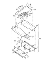
図1,2は、本発明にかかる表示要素形成方法によって製造された、一例として示す物品1Aの斜視図と、図1の物品1Aの部分破断分解斜視図とである。図1,2では、胴周り方向を矢印X、縦方向を矢印Yで示し、脚周り方向を矢印Z(図1のみ)で示す。なお、複合不織布2(複合ウェブ)を形成する第1および第2繊維不織布m1,m2(内側ウェブ,外側ウェブ)、パネル3を形成する繊維不織布m4およびフィルムm5の内面とは、コアm6に対向する面をいい、それらの外面とは、コアm6に非対向の面をいう(図2参照)。
【0011】
物品1Aは、肌非当接側に位置する実質的に不透液性の複合不織布2(複合ウェブ)と、複合不織布2の内側に取り付けられた液吸収性積層パネル3とから構成されている。物品1Aは、互いに対向する前胴周り域4および後胴周り域6と、それら胴周り域4,6の間に位置する股下域5とを有する。
【0012】
物品1Aは、胴周り方向へ延びるエンドフラップ7と、縦方向と脚周り方向とへ延びるサイドフラップ8とを有する。股下域5では、サイドフラップ8が物品1Aの胴周り方向内方へ向かって弧を画いている。物品1Aは、その展開平面形状が実質的に砂時計型を呈する。
【0013】
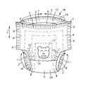
物品1Aでは、前後胴周り域4,6のサイドフラップ8が合掌状に重なり合い、それら胴周り域4,6のサイドフラップ8が縦方向へ間欠的に並ぶ多数の熱融着線9を介して固着されている。物品1Aは、パンツ型を呈し、胴周り開口10とその下方に一対の脚周り開口11とを有する。
【0014】
エンドフラップ7には、胴周り方向へ延びる複数条の第1伸縮性弾性部材14(胴周り用弾性部材)が収縮可能に取り付けられている。サイドフラップ8には、脚周り方向へ延びる複数条の第2伸縮性弾性部材15(脚周り用弾性部材)と第3伸縮性弾性部材16(脚周り用弾性部材)とが収縮可能に取り付けられている。
【0015】
前後胴周り域4,6の胴周り方向中央部には、物品1Aの外側から目視可能な表示要素13を有するインジケーションシート12が取り付けられている。表示要素13は、インジケーションシート12に印刷された熊の顔のイラストである。表示要素13は、イラストの他に、模様や文字、図形であってもよい。
【0016】
複合不織布2は、透湿性かつ疎水性第1繊維不織布m1(外側ウェブ)と、不織布m1の内側に位置する透湿性かつ疎水性第2繊維不織布m2(内側ウェブ)とから形成されている。複合不織布2は、物品1Aの前後胴周り域4,6と股下域5の一部とを形成している。
【0017】
インジケーションシート12は、透湿性かつ不透液性プラスチックフィルムm3から形成されている。インジケーションシート12は、透湿性かつ疎水性繊維不織布から形成されていてもよい。
【0018】
第1繊維不織布m1と第2繊維不織布m2とは、それら不織布m1,m2の内外面がホットメルト型接着剤(図示せず)を介して固着されている。接着剤は、第1繊維不織布m1の内面全域に間欠的に塗布されている。
【0019】
インジケーションシート12と第1および第2伸縮性弾性部材14,15とは、第1繊維不織布m1と第2繊維不織布m2との間に介在し、不織布m1の内面に固着されている。インジケーションシート12は、第2繊維不織布m2に非固着の状態にある。
【0020】
なお、接着剤は、第1繊維不織布m1の内面全域と第2繊維不織布m2の外面全域とに塗布されていてもよい。この場合は、インジケーションシート12が第1繊維不織布m1の内面と第2繊維不織布m2の外面とに固着される。
【0021】
パネル3は、砂時計型を呈し、股下域5から前後胴周り域4,6へ向かって延びている。パネル3は、肌当接側に位置する透湿性かつ親水性繊維不織布m4と、肌非当接側に位置する透湿性かつ不透液性プラスチックフィルムm5と、不織布m4とフィルムm5との間に介在する吸液性コアm6とから形成されている。パネル3は、それを形成するフィルムm5の外面がホットメルト型接着剤(図示せず)を介して第2繊維不織布m2の内面に固着されている。接着剤は、フィルムm5の外面の一部に間欠的に塗布されている。
【0022】
不織布m4は、その面積がコアm6の上面のそれよりもわずかに大きく、コアm6の上面全域を覆っている。フィルムm5は、その面積がコアm6の下面のそれよりもわずかに大きく、コアm6の下面全域を覆っている。不織布m4とフィルムm5とは、コアm6の両端縁17の外側に位置する両端部19,21と、コアm6の両側縁18の外側に位置する両側部20,22とを有する。
【0023】
不織布m4は、ホットメルト型接着剤(図示せず)を介してその内面がコアm6の上面に固着されている。フィルムm5は、ホットメルト型接着剤(図示せず)を介してその内面がコアm6の下面に固着されている。接着剤は、不織布m4の内面全域とフィルムm5の内面全域とに間欠的に塗布されている。
【0024】
不織布m4とフィルムm5とは、それらの両端部19,21どうしと両側部20,22どうしとが固着されている。第3伸縮性弾性部材16は、不織布m4とフィルムm5との間に介在し、それらの両側部20,22に固着されている。
【0025】
コアm6は、フラッフパルプと高吸収性ポリマー粒子との混合物、または、フラッフパルプと高吸収性ポリマー粒子と熱可塑性合成樹脂繊維との混合物であり、所与厚みに圧縮されている。コアm6は、その型くずれやポリマー粒子の脱落を防止するため、全体がティッシュペーパーや親水性繊維不織布等の透液性シートに被覆されていることが好ましい。
【0026】
エンドフラップ7は、コアm6の両端縁17から縦方向外方へ延びる不織布m1,m2,m4とフィルムm5とから形成されている。サイドフラップ8は、コアm6の両側縁18から胴周り方向外方へ延びる不織布m1,m2,m4とフィルムm5とから形成されている。
【0027】
接着剤は、第1および第2繊維不織布m1,m2や繊維不織布m4、フィルムm5にスパイラル状、ジグザグ状、ドット状、縞状のうちのいずれかの態様で塗布することが好ましい。接着剤をこのような態様で塗布した場合、第1および第2繊維不織布m1,m2や繊維不織布m4、フィルムm5に接着剤が塗布された部分と接着剤が塗布されていない部分とが生じる。
【0028】
図3,4は、表示要素形成方法の一例を示す概略斜視図と、図3から続く表示要素形成方法の概略斜視図とである。図5は、図4から続く表示要素形成方法の概略斜視図である。それら図では、長手方向を矢印Xで示し、幅方向を矢印Yで示す。この方法では、以下に示す手段を経ることによって図1の物品1Aが製造されるとともに、物品1Aの前後胴周り域4,6に表示要素13が形成される。
【0029】
シート配列手段S1;シート配列手段S1では、長手方向へ連続して移動する外側ウェブ30の上面(内面)に、一対の表示要素13を有する多数のインジケーションシート12が順次供給される。外側ウェブ30は、矢印X1で示す長手方向前方へ一定の速度で移動している。インジケーションシート12は、外側ウェブ30の上面に長手方向へ所定の寸法離間した状態で配列される。外側ウェブ30の上面には、インジケーションシート12が長手方向へ一定間隔で並ぶ。
【0030】
インジケーションシート12は、幅方向へ長い矩形を呈し、長手方向へ延びる両端部31と幅方向へ延びる両側部32とを有する。インジケーションシート12は、幅寸法が外側ウェブ30のそれよりも小さく、その両端部31が外側ウェブ30の両側縁部33の内側に位置している。表示要素13は、熊の顔のイラストであり、熊の顔が2つ幅方向へ並んでいる。それらイラストは、インジケーションシート12に印刷されており、互いに鏡像関係にある。
【0031】
外側ウェブ30は、透湿性かつ疎水性繊維不織布m1(第1繊維不織布)から形成されている。インジケーションシート12は、透湿性かつ不透液性プラスチックフィルムm3から形成されている。
【0032】
シート固着手段S2;シート固着手段S2では、外側ウェブ30の幅寸法を二分する長手方向仮想線Lの両側に個々の表示要素13を位置させた状態で、外側ウェブ30の上面にインジケーションシート12が固着される。外側ウェブ30とインジケーションシート12とは、外側ウェブ30の上面全域に間欠的に塗布されたホットメルト型接着剤(図示せず)を介して固着されている。
【0033】
シート固着手段S2では、長手方向へ連続する複数条の第1伸縮性弾性部材14(胴周り用弾性部材)が外側ウェブ30の両側縁部33の上面に伸長状態で取り付けられるとともに、幅方向へ延びる複数条の第2伸縮性弾性部材15(脚周り用弾性部材)が外側ウェブ30の上面に伸長状態で取り付けられる(弾性部材装着手段S8)。
【0034】
第1伸縮性弾性部材14は、インジケーションシート12の両端部31の外側に位置している。第2伸縮性弾性部材15は、インジケーションシート12の両側部32の外側に位置している。第1および第2伸縮性弾性部材14,15は、外側ウェブ30の上面にホットメルト型接着剤を介して固着されている。
【0035】
シート固着手段S2では、図示はしていないが、互いに対向配置されて回動する一対のニップロールの間に外側ウェブ30とインジケーションシート12と第1および第2伸縮性弾性部材14,15とが進入し、それらがニップロールの圧力によって加圧され、外側ウェブ30にインジケーションシート12と第1および第2伸縮性弾性部材14,15とが固着される。
【0036】
複合ウェブ成形手段S3;複合ウェブ成形手段S3では、外側ウェブ30の上面に長手方向へ連続して移動する内側ウェブ34の下面(外面)を重ね合わせた後、インジケーションシート12を挟んだ状態で、外側ウェブ30と内側ウェブ34とがホットメルト型接着剤を介して固着される。
【0037】
複合ウェブ成形手段S3では、外側ウェブ30と内側ウェブ34とから複合ウェブ35(複合不織布2)が形成される。なお、インジケーションシート12と内側ウェブ34とは、非固着の状態にある。
【0038】
内側ウェブ34は、外側ウェブ30と同一の速度で矢印X2で示す長手方向前方へ移動している。内側ウェブ34は、透湿性かつ疎水性繊維不織布m2(第2繊維不織布)から形成されている。
【0039】
複合ウェブ成形手段S3では、図示はしていないが、互いに対向配置されて回動する一対のニップロールの間に外側ウェブ30と内側ウェブ34とが進入し、ウェブ30,34がニップロールの圧力によって加圧され、それらウェブ30,34どうしが固着される。
【0040】
なお、接着剤は、外側ウェブ30の上面全域のみならず、内側ウェブ34の下面全域に塗布されていてもよい。この場合は、インジケーションシート12が外側ウェブ30と内側ウェブ34とに固着される。
【0041】
表示要素分割手段S4;表示要素分割手段S4では、複合ウェブ35とインジケーションシート12と弾性部材15とが仮想線L上に延びる切断線K1で切断され、それらが幅方向へ二分される。
【0042】
表示要素分割手段S4では、複合ウェブ35が第1複合ウェブ36と第2複合ウェブ37とに分割されるとともに、一対の表示要素13が個々のそれらに分割される。インジケーションシート12の表示要素13は、その一方が第1複合ウェブ36に位置し、その他方が第2複合ウェブ37に位置する。
【0043】
第1および第2複合ウェブ離間手段S5;第1および第2複合ウェブ離間手段S5では、インジケーションシート12それぞれを幅方向へ互いに並列させた状態で、第1複合ウェブ36と第2複合ウェブ37とを矢印Y1で示す幅方向外方へ所定の寸法離間させる。
【0044】
パネル固着手段S6;パネル固着手段S6では、第1および第2複合ウェブ36,37の上面に幅方向へ延びる多数の液吸収性積層パネル3が順次供給される。パネル3は、長手方向へ所定の寸法離間してそれら複合ウェブ36,37に配列される。複合ウェブ36,37の上面には、パネル3が長手方向へ一定間隔で並ぶ。
【0045】
パネル固着手段S6では、パネル3の幅方向両端部38がインジケーションシート12上に位置した状態で、ホットメルト型接着剤(図示せず)を介して第1および第2複合ウェブ36,37の上面とパネル3の下面とが固着される。
【0046】
パネル3は、透湿性かつ親水性繊維不織布m4と、透湿性かつ不透液性プラスチックフィルムm5と、それらの間に介在する吸液性コアm6とから形成されている(図2参照)。パネル3の両側部39には、幅方向へ延びる第3伸縮性弾性部材16(脚周り用弾性部材)が伸長状態で取り付けられている。
【0047】
パネル3は、それを形成するフィルムm5の下面(外面)が第1および第2複合ウェブ36,37の上面に固着されている。接着剤は、フィルムm5の下面の一部に間欠的に塗布されている。
【0048】
パネル3では、ホットメルト型接着剤(図示せず)を介して、不織布m4の下面(内面)とコアm6の上面とが固着され、フィルムm5の上面(内面)とコアm6の下面とが固着されている。不織布m4とフィルムm5とは、それらの両端部19,21と両側部20,22とが固着されている。第3伸縮性弾性部材16は、不織布m4とフィルムm5との間に介在し、それらに固着されている。接着剤は、不織布m4の下面全域とフィルムm5の上面全域とに間欠的に塗布されている。
【0049】
パネル固着手段S6では、図示はしていないが、互いに対向配置されて回動する一対のニップロールの間に複合ウェブ36,37とパネル3とが進入し、それらがニップロールの圧力によって加圧され、ウェブ36,37とパネル3とが固着される。
【0050】
物品成形手段S7;物品成形手段S7では、第1および第2複合ウェブ36,37とパネル3の両側部39とが隣り合うパネル3の間を幅方向へ横切る切断線K2,K3で切断される。幅方向へ互いに離間するそれら複合ウェブ36,37の間では、複合ウェブ36,37の一部とパネル3の両側部39とがコアm6へ向かって弧を画く切断線K2で切除され、脚周り用切欠縁が形成される。さらに、複合ウェブ36,37は、幅方向へ直状に延びる切断線K3で切断される。複合ウェブ36,37とパネル3の両側部39とが切断されると、長手方向へ並ぶ多数の物品1Aが作られる。
【0051】
物品1Aは、その平面形状が実質的に砂時計型を呈し、幅方向に前胴周り域4および後胴周り域6と、それら胴周り域4,6の間に位置する股下域5とを有する。
【0052】
複合ウェブ36,37とパネル3の両側部39とを切断した後は、パネル3を内側にした状態で、仮想線Lを折曲部としてパネル3を幅方向内方へ折曲し、前胴周り域4の複合ウェブ36と後胴周り域6の複合ウェブ37とを重ね合わせる。次に、それら複合ウェブ36,37どうしを熱融着線9で固着し、パンツ型に成形する。
【0053】
図6,7は、本発明の表示要素形成方法によって製造された、他の一例として示す物品1Bの斜視図と、図6の物品1Bの部分破断分解斜視図とである。図6,7では、胴周り方向を矢印X、縦方向を矢印Yで示し、脚周り方向を矢印Z(図6のみ)で示す。なお、中間シート23を形成するフィルムm7と不織布m8との内面とは、コアm6に対向する面をいい、それらの外面とは、コアm6に非対向の面をいう(図7参照)。
【0054】
物品1Bは、実質的に不透液性の複合不織布2(複合ウェブ)と、不織布2の内側に取り付けられた不透液性の中間シート23と、不織布2とシート23との内側に取り付けられた液吸収性パネル3とから構成されている。
【0055】
物品1Bは、互いに対向する前胴周り域4および後胴周り域6と、それら胴周り域4,6の間に位置する股下域5とを有し、胴周り方向へ延びるエンドフラップ7と、縦方向と脚周り方向とへ延びるサイドフラップ8とを有する。
【0056】
物品1Bは、パンツ型を呈し、胴周り開口10と一対の脚周り開口11とを有する。物品1Bでは、複合不織布2が前後胴周り域4,6に位置し、中間シート23が股下域5に位置している。
【0057】
エンドフラップ7には、胴周り方向へ延びる複数条の第1伸縮性弾性部材14(胴周り用弾性部材)が収縮可能に取り付けられている。サイドフラップ8には、脚周り方向へ延びる複数条の第2伸縮性弾性部材15(脚周り用弾性部材)と第3伸縮性弾性部材16(脚周り用弾性部材)とが収縮可能に取り付けられている。
【0058】
前後胴周り域4,6の胴周り方向中央部には、熊の顔のイラスト(表示要素13)が印刷されたインジケーションシート12が取り付けられている。インジケーションシート12は、透湿性かつ不透液性プラスチックフィルムm3から形成されている。
【0059】
複合不織布2は、透湿性かつ疎水性第1繊維不織布m1(外側ウェブ)と、透湿性かつ疎水性第2繊維不織布m2(内側ウェブ)とから形成されている。第1繊維不織布m1と第2繊維不織布m2とは、それら不織布m1,m2の内外面がホットメルト型接着剤(図示せず)を介して固着されている。接着剤は、第1繊維不織布m1の内面全域に間欠的に塗布されている。
【0060】
インジケーションシート12と第1および第2伸縮性弾性部材14,15とは、第1繊維不織布m1と第2繊維不織布m2との間に介在し、不織布m1の内面に固着されている。インジケーションシート12は、第2繊維不織布m2に非固着の状態にある。
【0061】
中間シート23は、互いに重なり合う透湿性かつ不透液性プラスチックフィルムm7と、透湿性かつ疎水性繊維不織布m8とから形成されている。中間シート23は、砂時計型を呈し、その面積がパネル3のそれよりも小さく、股下域5においてコアm6の下面を覆っている(図7参照)。
【0062】
中間シート23は、不織布m8の一部に間欠的に塗布されたホットメルト型接着剤(図示せず)を介して不織布m2の内面に固着されている。フィルムm7と不織布m8とは、ホットメルト型接着剤(図示せず)を介して固着されている。中間シート23は、透湿性かつ不透液性プラスチックフィルムm7と透湿性かつ疎水性繊維不織布m8とのうちのいずれか一方から形成されていてもよい。
【0063】
パネル3は、肌当接側に位置する透湿性かつ親水性繊維不織布m4と、不織布m4の内面に固着された吸液性コアm6とから形成されている。不織布m4は、その面積がコアm6の上面のそれよりもわずかに大きく、コアm6の上面全域を覆っている。不織布m4は、コアm6の両端縁17の外側に位置する両端部19と、コアm6の両側縁18の外側に位置する両側部20とを有する。第3伸縮性弾性部材16は、ホットメルト型接着剤(図示せず)を介して不織布m4の両側部20に固着されている。
【0064】
パネル3では、前後胴周り域4,6に位置する不織布m4の両端部19と両側部20とがホットメルト型接着剤(図示せず)を介して第2繊維不織布m2の内面に固着され、股下域5に位置する不織布m4の両側部20がホットメルト型接着剤(図示せず)を介してフィルムm7の内面に固着されている。コアm6の下面は、ホットメルト型接着剤(図示せず)を介してフィルムm7の内面に固着されている。接着剤は、不織布m4の内面全域とフィルムm7の内外面全域とに間欠的に塗布されている。
【0065】
エンドフラップ7は、コアm6の両端縁17から縦方向外方へ延びる不織布m1,m2,m4から形成されている。サイドフラップ8は、コアm6の両側縁18から胴周り方向外方へ延びる不織布m1,m2,m4,m8とフィルムm7とから形成されている。
【0066】
図8,9は、表示要素形成方法の他の一例を示す概略斜視図と、図8から続く表示要素形成方法の概略斜視図とであり、図10は、図9から続く表示要素形成方法の概略斜視図である。それら図では、長手方向を矢印Xで示し、幅方向を矢印Yで示す。この方法では、以下に示す手段を経ることによって図6の物品1Bが製造されるとともに、物品1Bの前後胴周り域4,6に表示要素が形成される。
【0067】
シート配列手段S1;シート配列手段S1では、長手方向へ連続して移動する外側ウェブ30の上面(内面)に、一対の表示要素13を有する多数のインジケーションシート12が順次供給される。インジケーションシート12は、外側ウェブ30の上面に長手方向へ所定の寸法離間した状態で配列される。外側ウェブ30の上面には、インジケーションシート12が長手方向へ一定間隔で並ぶ。表示要素13は、熊の顔のイラストであり、熊の顔が2つ幅方向へ並んでいる。それらイラストは、インジケーションシート12に印刷されており、互いに鏡像関係にある。
【0068】
外側ウェブ30は、透湿性かつ疎水性繊維不織布m1(第1繊維不織布)から形成されている。インジケーションシート12は、透湿性かつ不透液性プラスチックフィルムm3から形成されている。
【0069】
シート固着手段S2;シート固着手段S2では、仮想線Lの両側に個々の表示要素13を位置させた状態で、外側ウェブ30の上面にインジケーションシート12が固着される。外側ウェブ30とインジケーションシート12とは、外側ウェブ30の上面全域に間欠的に塗布されたホットメルト型接着剤(図示せず)を介して固着されている。
【0070】
シート固着手段S2では、長手方向へ連続する複数条の第1伸縮性弾性部材14(胴周り用弾性部材)と幅方向へ延びる複数条の第2伸縮性弾性部材15(脚周り用弾性部材)とが外側ウェブ30の上面に伸長状態で取り付けられる(弾性部材装着手段S8)。
【0071】
複合ウェブ成形手段S3;複合ウェブ成形手段S3では、外側ウェブ30の上面に長手方向へ連続して移動する内側ウェブ34の下面(外面)を重ね合わせた後、外側ウェブ30と内側ウェブ34とが固着される。
【0072】
複合ウェブ成形手段S3では、外側ウェブ30と内側ウェブ34とから複合ウェブ35(複合不織布2)が形成される。なお、インジケーションシート12と内側ウェブ34とは、非固着の状態にある。内側ウェブ34は、透湿性かつ疎水性繊維不織布m2(第2繊維不織布)から形成されている。
【0073】
表示要素分割手段S4;表示要素分割手段S4では、複合ウェブ35とインジケーションシート12と弾性部材15とが仮想線L上に延びる切断線K1で切断され、それらが幅方向へ二分される。
【0074】
表示要素分割手段S4では、複合ウェブ35が第1複合ウェブ36と第2複合ウェブ37とに分割されるとともに、一対の表示要素13が個々のそれらに分割される。
【0075】
第1および第2複合ウェブ離間手段S5;第1および第2複合ウェブ離間手段S5では、インジケーションシート12それぞれを幅方向へ互いに並列させた状態で、第1複合ウェブ36と第2複合ウェブ37とを矢印Y1で示す幅方向外方へ所定の寸法離間させる。
【0076】
パネル固着手段S6;パネル固着手段S6では、第1および第2複合ウェブ36,37の上面(内面)に幅方向へ延びる多数の中間シート23が順次供給される。中間シート23は、それら複合ウェブ36,37の上面に長手方向へ所定の寸法離間した状態で配列される(中間シート配列手段S9)。
【0077】
中間シート23は、互いに離間するインジケーションシート12の間に位置し、インジケーションシート12の一部に重なっている。複合ウェブ36,37の上面には、中間シート23が長手方向へ一定間隔で並ぶ。次に、中間シート23の下面がそれら複合ウェブ36,37の上面に固着される(第1中間シート固着手段S10)。第1および第2複合ウェブ36,37と中間シート23とは、後記する不織布m8の一部に間欠的に塗布されたホットメルト型接着剤(図示せず)を介して固着されている。
【0078】
パネル固着手段S6では、中間シート23の上面に幅方向へ延びる多数の液吸収性積層パネル3が順次供給される。パネル3の幅方向両端部38は、インジケーションシート12上に位置している。次に、ホットメルト型接着剤(図示せず)を介してパネル3の下面と中間シート23の上面とが固着される(第2中間シート固着手段S11)。さらに、パネル3の幅方向両端部38がホットメルト型接着剤(図示せず)を介して複合ウェブ36,37の上面に固着される。
【0079】
中間シート23は、砂時計型を呈し、透湿性かつ不透液性プラスチックフィルムm7と、透湿性かつ疎水性繊維不織布m8とから形成されている。パネル3は、透湿性かつ親水性繊維不織布m4と、不織布m4の下面に位置する吸液性コアm6とから形成されている(図7参照)。パネル3の両側部39には、幅方向へ延びる伸縮性弾性部材16(脚周り用弾性部材)が伸長状態で取り付けられている。
【0080】
パネル3では、ホットメルト型接着剤(図示せず)を介して不織布m4の下面とコアm6の上面とが固着されている。不織布m4の両端部19と両側部20とは、ホットメルト型接着剤(図示せず)を介して第1および第2ウェブ36,37の上面とフィルムm7の上面とに固着されている。コアm6の下面は、ホットメルト型接着剤(図示せず)を介してフィルムm7の上面に固着されている。接着剤は、不織布m4の下面全域とフィルムm7の上下面全域とに間欠的に塗布されている。
【0081】
中間シート23は、第1および第2複合ウェブ離間手段S5で供給され、複合ウェブ36,37の上面に長手方向へ一定間隔で配列されてもよく、中間シート23の下面が第1および第2複合ウェブ離間手段S5において複合ウェブ36,37の上面に固着されてもよい。
【0082】
物品成形手段S7;物品成形手段S7では、第1および第2複合ウェブ36,37とパネル3の両側部39とが隣り合うパネル3の間を幅方向へ横切る切断線K2,K3で切断される。
【0083】
幅方向へ互いに離間するそれら複合ウェブ36,37の間では、複合ウェブ36,37の一部とパネル3の両側部39とがコアm6へ向かって弧を画く切断線K2で切除され、脚周り用切欠縁が形成される。さらに、複合ウェブ36,37は、幅方向へ直状に延びる切断線K3で切断される。複合ウェブ36,37とパネル3の両側部39とが切断されると、長手方向へ並ぶ多数の物品1Bが作られる。
【0084】
物品1Bは、その平面形状が実質的に砂時計型を呈し、幅方向に前胴周り域4および後胴周り域6と、それら胴周り域4,6の間に位置する股下域5とを有する。
【0085】
複合ウェブ36,37とパネル3の両側部39とを切断した後は、パネル3を内側にした状態で、仮想線Lを折曲部としてパネル3と中間シート23とを幅方向内方へ折曲し、前胴周り域4の複合ウェブ36と後胴周り域6の複合ウェブ37とを重ね合わせる。次に、前後胴周り域4,6の複合ウェブ36,37どうしを熱融着線9で固着し、パンツ型に成形する。
【0086】
不織布m1,m2,m4,m8には、スパンレース、ニードルパンチ、メルトブローン、サーマルボンド、スパンポンド、ケミカルボンド、エアースルー、の各製法により製造されたものを使用することができる。不織布の構成繊維としては、ポリオレフィン系、ポリエステル系、ポリアミド系、の各繊維、ポリエチレン/ポリプロピレンやポリエチレン/ポリエステルからなる芯鞘型複合繊維または並列型複合繊維を使用することができる。
【0087】
フィルムm3,m5,m7には、ポリオレフィン系熱可塑性合成樹脂を使用することが好ましい。フィルムは、その透湿度が2150〜4000g/m2・24hrsの範囲にあることが好ましい。
【0088】
それら図示の表示要素形成方法におけるシート配列手段S1とシート固着手段S2とでは、図示はしていないが、長手方向へ連続して移動する内側ウェブ34の下面(外面)に、一対の表示要素13を有する多数のインジケーションシート12が順次供給され、インジケーションシート12が内側ウェブ34の下面に長手方向へ所定の寸法離間した状態で配列されてもよい。この場合は、内側ウェブ34の幅寸法を二分する長手方向仮想線の両側に個々の表示要素13を位置させた状態で、内側ウェブ34の下面にインジケーションシート12が固着される。内側ウェブ34とインジケーションシート12とは、内側ウェブ34の下面全域に間欠的に塗布されたホットメルト型接着剤(図示せず)を介して固着される。
【0089】
また、シート固着手段S2では、図示はしていないが、長手方向へ連続する複数条の第1伸縮性弾性部材14(胴周り用弾性部材)が内側ウェブ34の両側縁部の下面に伸長状態で取り付けられてもよく、幅方向へ延びる複数条の第2伸縮性弾性部材15(脚周り用弾性部材)が内側ウェブ34の下面に伸長状態で取り付けられてもよい(弾性部材装着手段S8)。この場合は、第1伸縮性弾性部材14がインジケーションシート12の両端部31の外側に位置し、第2伸縮性弾性部材15がインジケーションシート12の両側部32の外側に位置する。第1および第2伸縮性弾性部材14,15は、内側ウェブ34の下面にホットメルト型接着剤を介して固着される。内側ウェブ34にインジケーションシート12と第1および第2伸縮性弾性部材14,15とを固着した場合では、内側ウェブ34の下面に長手方向へ連続して移動する外側ウェブ30の上面(内面)を重ね合わせた後、外側ウェブ30と内側ウェブ34とが固着される(複合ウェブ成形手段S3)。
【0090】
この発明は、あらかじめ前後胴周り域4,6が連結されたパンツ型の使い捨て着用物品1A,1Bの他に、着用時に前後胴周り域を連結するオープン型の使い捨て着用物品にも実施することができる。
【0091】
【発明の効果】
本発明にかかる表示要素形成方法によれば、一対の表示要素を有するインジケーションシートを二分し、それら表示要素を個々のそれらに分割するとともに、二分したインジケーションシートを互いに所定寸法離間させることで、物品の前後胴周り域における肌非当接面に一度に表示要素を形成することができる。この方法では、表示要素を前後胴周り域に別々に取り付けるための装置や工程を必要としないので、物品を廉価に製造することができる。
【0092】
この方法では、インジケーションシートの表示要素が互いに鏡像関係にあるので、前後胴周り域に形成された表示要素のうちの一方が他方に対して上下逆さまになってしまうことはない。
【図面の簡単な説明】
【図1】一例として示す物品の斜視図。
【図2】図1の物品の部分破断分解斜視図。
【図3】表示要素形成方法の一例を示す概略斜視図。
【図4】図3から続く表示要素形成方法の概略斜視図。
【図5】図4から続く表示要素形成方法の概略斜視図。
【図6】他の一例として示す物品の斜視図。
【図7】図7の物品の部分破断分解斜視図。
【図8】表示要素形成方法の他の一例を示す概略斜視図。
【図9】図8から続く表示要素形成方法の概略斜視図。
【図10】図9から続く表示要素形成方法の概略斜視図。
【符号の説明】
1A 使い捨て着用物品
1B 使い捨て着用物品
2 複合不織布(複合ウェブ)
3 吸液性積層パネル
4 前胴周り域
5 股下域
6 後胴周り域
12 インジケーションシート
13 表示要素
14 第1伸縮性弾性部材
15 第2伸縮性弾性部材
23 中間シート
30 外側ウェブ
34 内側ウェブ
35 複合ウェブ(複合不織布)
36 第1複合ウェブ
37 第2複合ウェブ
38 幅方向両端部
39 両側部
L 長手方向仮想線
m1 透湿性かつ疎水性繊維不織布(外側ウェブ)
m2 透湿性かつ疎水性繊維不織布(内側ウェブ)
m3 透湿性かつ不透液性プラスチックフィルム
m4 透湿性かつ親水性繊維不織布
m6 吸液性コア
m7 透湿性かつ不透液性プラスチックフィルム
m8 透湿性かつ疎水性繊維不織布
S1 シート配列手段
S2 シート固着手段
S3 複合ウェブ成形手段
S4 表示要素分割手段
S5 第1および第2複合ウェブ離間手段
S6 パネル固着手段
S7 物品成形手段
S8 弾性部材装着手段
S9 中間シート配列手段
S10 第1中間シート固着手段
S11 第2中間シート固着手段[0001]
BACKGROUND OF THE INVENTION
The present invention relates to a display element forming method for forming a display element that is visible from the outside of an article on a skin non-contact surface in a front and back waist area of a disposable wearing article.
[0002]
[Prior art]
Japanese Patent Laid-Open No. 2001-54536 discloses a pants-type disposable diaper having a pattern sheet and a method for manufacturing the same. This diaper is composed of a liquid-permeable inner sheet positioned on the skin contact side, a liquid-impermeable outer sheet positioned on the skin non-contact side, and a liquid-absorbent core interposed between the sheets. Yes. The diaper includes a front waistline region and a back waistline region, and a crotch region positioned between the waistline regions, and includes a waistline opening and a pair of leg opening. A pattern sheet having a pattern visible from the outside of the diaper is attached to the area around the front waist. The pattern sheet is fixed to the inner surface of the outer sheet.
[0003]
This diaper manufacturing method includes a pattern sheet fixing means for fixing a pattern sheet having a smaller area than the outer sheet to a predetermined position on the inner surface of the outer sheet, a core fixing means for fixing a core to the inner surface of the outer sheet, and an upper surface of the core. And a sheet adhering means for adhering the inner sheets by overlapping them. The pattern sheet fixing means sequentially supplies a large number of pattern sheets to the inner surface of the outer sheet, and after arranging the individual pattern sheets at regular intervals in the longitudinal direction of the outer sheet, these pattern sheets are interposed via a hot melt adhesive. To the outer sheet.
[0004]
[Problems to be solved by the invention]
In the diaper manufacturing method disclosed in the publication, when the pattern sheet is attached to the front waistline region and the back waistline region, the pattern sheet is arranged in a state in which a large number of pattern sheets are spaced apart in parallel in the width direction of the outer sheet. Must be separately supplied to the inner surface of the outer sheet, and the pattern sheets must be separately fixed to the outer sheet. If these pattern sheets are supplied and fixed separately, it takes time and effort to fix the pattern sheet twice, and an apparatus and a process therefor are required, so that a diaper cannot be manufactured at low cost.
[0005]
The subject of this invention is providing the display element formation method which can form a display element at once in the front-back trunk periphery area | region of a disposable wearing article, without taking time and effort twice.
[0006]
[Means for Solving the Problems]
The premise of the present invention for solving the above-mentioned problems is a crotch region composed of a composite web and a liquid-absorbing laminated panel attached thereto, and located between the front waist region and the rear waist region and the waist region. A display element forming method of forming a display element visible from the outside of the article on a skin non-contact surface in the front and rear waist area of the disposable wearing article provided with a zone.
[0007]
A feature of the present invention based on the premise is that a number of indication sheets having a pair of display elements arranged in the width direction are sequentially arranged on either the upper surface of the continuous outer web moving in the longitudinal direction or the lower surface of the continuous inner web. And sheet arrangement means for arranging the indication sheets at regular intervals in the longitudinal direction,
The indication sheet is fixed to either the upper surface of the outer web or the lower surface of the inner web in a state where the individual display elements are positioned on both sides of a longitudinal imaginary line that bisects the width dimension of the webs. Sheet fixing means,
A composite web forming means for superposing the upper surface of the outer web and the lower surface of the inner web and fixing the outer web and the inner web in a state of sandwiching the indication sheet;
A display element that cuts the composite web and the indication sheet along the virtual line, divides the composite web into a first composite web and a second composite web, and divides the pair of display elements into individual ones. Dividing means,
First and second composite web separating means for separating the first composite web and the second composite web by a predetermined dimension outward in the width direction in a state where the indication sheets are parallel to each other in the width direction;
A large number of the liquid-absorbing laminated panels extending in the width direction are sequentially supplied to the upper surfaces of the first and second composite webs, the panels are arranged at regular intervals in the longitudinal direction, and both ends in the width direction of the panels are Panel fixing means for fixing the upper surfaces of the first and second composite webs and the lower surface of the panel in a state of being positioned on the indication sheet;
A large number of the articles arranged in the longitudinal direction by cutting at least the first and second composite webs of the first and second composite webs and both side portions of the panel between the adjacent panels in the width direction. Article molding means for molding,
It is in having.
[0008]
The present invention has the following embodiments.
(1) The sheet fixing means includes a first elastic elastic member located on both sides in the width direction of the indication sheet and continuous in the longitudinal direction on either the upper surface of the outer web or the lower surface of the inner web. Attached in an extended state, a second stretchable elastic member positioned between adjacent indication sheets and extending in the width direction is attached in an extended state to either the upper surface of the outer web or the lower surface of the inner web .
(2) One of the first and second composite web separating means and the panel fixing means sequentially supplies a large number of intermediate sheets extending in the width direction on the upper surfaces of the first and second composite webs. And intermediate sheet arranging means for arranging the intermediate sheets at regular intervals in the longitudinal direction so as to be positioned between the indication sheets spaced apart from each other, upper surfaces of the first and second composite webs, and lower surfaces of the intermediate sheets And a first intermediate sheet fixing means for fixing
The panel fixing means has second intermediate sheet fixing means for fixing the lower surface of the panel and the upper surface of the intermediate sheet.
(3) The outer web and the inner web are formed of a moisture-permeable and hydrophobic fiber nonwoven fabric, and the intermediate sheet is formed of a moisture-permeable and liquid-impervious plastic film and a moisture-permeable and hydrophobic fiber nonwoven fabric. It is formed from at least one.
(4) The said panel is formed from the moisture-permeable and hydrophilic fiber nonwoven fabric and the liquid-absorbent core located in the lower surface of the said fiber nonwoven fabric.
(5) The indication sheet is formed of any one of a moisture-permeable and hydrophobic fiber nonwoven fabric and a moisture-permeable and liquid-impervious plastic film.
(6) The display element is an illustration printed on the indication sheet.
(7) In the indication sheet, the pair of display elements are mirror images of each other.
[0009]
DETAILED DESCRIPTION OF THE INVENTION
Details of the display element forming method according to the present invention will be described with reference to the accompanying drawings.
[0010]
1 and 2 are a perspective view of an
[0011]
1 A of articles | goods are comprised from the substantially liquid impervious composite nonwoven fabric 2 (composite web) located in the skin non-contact side, and the liquid absorptive laminated
[0012]
1 A of articles | goods have the
[0013]
In the
[0014]
A plurality of first elastic elastic members 14 (elastic members for the waist) extending in the waist direction are attached to the
[0015]
An
[0016]
The composite
[0017]
The
[0018]
In the first fiber nonwoven fabric m1 and the second fiber nonwoven fabric m2, the inner and outer surfaces of the nonwoven fabrics m1 and m2 are fixed via a hot-melt adhesive (not shown). The adhesive is intermittently applied to the entire inner surface of the first fiber nonwoven fabric m1.
[0019]
The
[0020]
The adhesive may be applied to the entire inner surface of the first fiber nonwoven fabric m1 and the entire outer surface of the second fiber nonwoven fabric m2. In this case, the
[0021]
The
[0022]
The area of the nonwoven fabric m4 is slightly larger than that of the upper surface of the core m6, and covers the entire upper surface of the core m6. The film m5 has an area slightly larger than that of the lower surface of the core m6, and covers the entire lower surface of the core m6. The nonwoven fabric m4 and the film m5 have both
[0023]
The inner surface of the nonwoven fabric m4 is fixed to the upper surface of the core m6 via a hot-melt adhesive (not shown). The inner surface of the film m5 is fixed to the lower surface of the core m6 via a hot melt adhesive (not shown). The adhesive is intermittently applied to the entire inner surface of the nonwoven fabric m4 and the entire inner surface of the film m5.
[0024]
The nonwoven fabric m4 and the film m5 have their both
[0025]
The core m6 is a mixture of fluff pulp and superabsorbent polymer particles, or a mixture of fluff pulp, superabsorbent polymer particles and thermoplastic synthetic resin fibers, and is compressed to a given thickness. The core m6 is preferably entirely covered with a liquid-permeable sheet such as tissue paper or a hydrophilic fiber nonwoven fabric in order to prevent deformation of the core and dropping of the polymer particles.
[0026]
The
[0027]
The adhesive is preferably applied to the first and second fiber nonwoven fabrics m1 and m2, the fiber nonwoven fabric m4, and the film m5 in any of a spiral shape, a zigzag shape, a dot shape, and a stripe shape. When the adhesive is applied in this manner, a portion where the adhesive is applied to the first and second fiber nonwoven fabrics m1, m2, fiber nonwoven fabric m4, and film m5 and a portion where the adhesive is not applied are generated.
[0028]
3 and 4 are a schematic perspective view showing an example of the display element forming method and a schematic perspective view of the display element forming method continued from FIG. FIG. 5 is a schematic perspective view of the display element forming method continued from FIG. In these drawings, the longitudinal direction is indicated by an arrow X, and the width direction is indicated by an arrow Y. In this method, the
[0029]
Sheet arrangement means S1; In the sheet arrangement means S1, a large number of
[0030]
The
[0031]
The
[0032]
Sheet fixing means S2; In the sheet fixing means S2, the
[0033]
In the sheet adhering means S <b> 2, a plurality of first stretchable elastic members 14 (cylinder circumference elastic members) continuous in the longitudinal direction are attached to the upper surfaces of the
[0034]
The first elastic
[0035]
In the sheet adhering means S2, although not shown, the
[0036]
Composite web forming means S3: In the composite web forming means S3, the lower surface (outer surface) of the
[0037]
In the composite web forming means S <b> 3, a composite web 35 (composite nonwoven fabric 2) is formed from the
[0038]
The
[0039]
In the composite web forming means S3, although not shown, the
[0040]
The adhesive may be applied not only to the entire upper surface of the
[0041]
Display element dividing means S4; In the display element dividing means S4, the
[0042]
In the display element dividing means S4, the
[0043]
First and second composite web separating means S5; In the first and second composite web separating means S5, the first
[0044]
Panel fixing means S6; In the panel fixing means S6, a large number of liquid-absorbing
[0045]
In the panel adhering means S6, the first and second
[0046]
The
[0047]
In the
[0048]
In
[0049]
In the panel adhering means S6, although not shown, the
[0050]
Article forming means S7: In the article forming means S7, the first and second
[0051]
The
[0052]
After cutting the
[0053]
FIGS. 6 and 7 are a perspective view of an article 1B manufactured by the display element forming method of the present invention as another example, and a partially broken exploded perspective view of the article 1B of FIG. 6 and 7, the direction around the trunk is indicated by an arrow X, the vertical direction is indicated by an arrow Y, and the direction around the legs is indicated by an arrow Z (only in FIG. 6). In addition, the inner surfaces of the film m7 and the nonwoven fabric m8 forming the
[0054]
The article 1B is attached to the inside of the substantially liquid-impervious composite nonwoven fabric 2 (composite web), the liquid-impervious
[0055]
The article 1B has a front waistline region 4 and a
[0056]
The article 1 </ b> B has a pants shape and has a trunk periphery opening 10 and a pair of
[0057]
A plurality of first elastic elastic members 14 (elastic members for the waist) extending in the waist direction are attached to the
[0058]
An
[0059]
The composite
[0060]
The
[0061]
The
[0062]
The
[0063]
The
[0064]
In the
[0065]
The
[0066]
8 and 9 are a schematic perspective view showing another example of the display element forming method and a schematic perspective view of the display element forming method continued from FIG. 8, and FIG. 10 is a diagram of the display element forming method continued from FIG. It is a schematic perspective view. In these drawings, the longitudinal direction is indicated by an arrow X, and the width direction is indicated by an arrow Y. In this method, the article 1B shown in FIG. 6 is manufactured through the following means, and display elements are formed in the front and
[0067]
Sheet arrangement means S1; In the sheet arrangement means S1, a large number of
[0068]
The
[0069]
Sheet fixing means S2: In the sheet fixing means S2, the
[0070]
In the sheet fixing means S2, a plurality of first stretchable elastic members 14 (body elastic members) continuous in the longitudinal direction and a plurality of second stretchable elastic members 15 (leg elastic members) extending in the width direction. Are attached to the upper surface of the
[0071]
Composite web forming means S3: In the composite web forming means S3, after the lower surface (outer surface) of the
[0072]
In the composite web forming means S <b> 3, a composite web 35 (composite nonwoven fabric 2) is formed from the
[0073]
Display element dividing means S4; In the display element dividing means S4, the
[0074]
In the display element dividing means S4, the
[0075]
First and second composite web separating means S5; In the first and second composite web separating means S5, the first
[0076]
Panel fixing means S6; In the panel fixing means S6, a large number of
[0077]
The
[0078]
In the panel fixing means S6, a large number of liquid-absorbing
[0079]
The
[0080]
In the
[0081]
The
[0082]
Article forming means S7: In the article forming means S7, the first and second
[0083]
Between the
[0084]
The article 1B has a substantially hourglass shape in plan, and has a front waistline region 4 and a
[0085]
After cutting the
[0086]
As the nonwoven fabrics m1, m2, m4, and m8, those manufactured by each method of spun lace, needle punch, melt blown, thermal bond, spun pond, chemical bond, and air through can be used. As the constituent fibers of the nonwoven fabric, polyolefin-based, polyester-based, polyamide-based fibers, core-sheath type composite fibers or parallel type composite fibers made of polyethylene / polypropylene or polyethylene / polyester can be used.
[0087]
It is preferable to use a polyolefin-based thermoplastic synthetic resin for the films m3, m5, and m7. The film has a moisture permeability of 2150 to 4000 g / m. 2 -It is preferable that it exists in the range of 24 hrs.
[0088]
In the illustrated display element forming method, the sheet arranging means S1 and the sheet adhering means S2 are not shown, but a pair of
[0089]
Further, in the sheet fixing means S2, although not shown, a plurality of first stretchable elastic members 14 (elastic members for the waist) extending in the longitudinal direction are extended on the lower surfaces of both side edges of the
[0090]
The present invention can be implemented not only in the pants-type disposable wearing
[0091]
【The invention's effect】
According to the display element forming method according to the present invention, an indication sheet having a pair of display elements is divided into two parts, the display elements are divided into individual parts, and the divided indication sheets are separated from each other by a predetermined dimension. A display element can be formed at a time on the non-skin contact surface in the front and back waist area of the article. In this method, since an apparatus and a process for separately attaching the display elements to the front and rear waist regions are not required, an article can be manufactured at a low cost.
[0092]
In this method, the display elements of the indication sheet are mirror images of each other, so that one of the display elements formed in the front and rear waist area is not upside down with respect to the other.
[Brief description of the drawings]
FIG. 1 is a perspective view of an article shown as an example.
2 is a partially broken exploded perspective view of the article of FIG.
FIG. 3 is a schematic perspective view showing an example of a display element forming method.
4 is a schematic perspective view of the display element forming method continued from FIG. 3. FIG.
FIG. 5 is a schematic perspective view of the display element forming method continued from FIG. 4;
FIG. 6 is a perspective view of an article shown as another example.
7 is a partially broken exploded perspective view of the article of FIG.
FIG. 8 is a schematic perspective view showing another example of the display element forming method.
FIG. 9 is a schematic perspective view of the display element forming method continued from FIG. 8;
10 is a schematic perspective view of the display element forming method continued from FIG. 9. FIG.
[Explanation of symbols]
1A disposable wearing article
1B Disposable wearing articles
2 Composite nonwoven fabric (composite web)
3 Liquid-absorbing laminated panels
4 Front waist area
5 Inseam
6 Rear waist area
12 Indication sheet
13 Display elements
14 1st elastic elastic member
15 Second elastic elastic member
23 Intermediate sheet
30 outer web
34 Inner web
35 Composite web (composite non-woven fabric)
36 First composite web
37 Second composite web
38 Both ends in the width direction
39 Both sides
L Longitudinal imaginary line
m1 Moisture permeable and hydrophobic fiber nonwoven fabric (outer web)
m2 Moisture-permeable and hydrophobic fiber nonwoven fabric (inner web)
m3 Moisture-permeable and liquid-impervious plastic film
m4 breathable and hydrophilic fiber nonwoven fabric
m6 absorbent core
m7 Moisture permeable and liquid impermeable plastic film
m8 Moisture permeable and hydrophobic fiber nonwoven fabric
S1 Sheet arrangement means
S2 Sheet fixing means
S3 Composite web forming means
S4 Display element dividing means
S5 first and second composite web separating means
S6 Panel fixing means
S7 Article molding means
S8 Elastic member mounting means
S9 Intermediate sheet arrangement means
S10 First intermediate sheet fixing means
S11 Second intermediate sheet fixing means
Claims (8)
長手方向へ移動する連続外側ウェブの上面と連続内側ウェブの下面とのいずれか一方に、幅方向へ並ぶ一対の前記表示要素を有する多数のインジケーションシートを順次供給するとともに、前記インジケーションシートを長手方向へ一定間隔で配列するシート配列手段、
それらウェブの幅寸法を二分する長手方向仮想線の両側に個々の前記表示要素を位置させた状態で、前記外側ウェブの上面と前記内側ウェブの下面とのいずれか一方に前記インジケーションシートを固着するシート固着手段、
前記外側ウェブの上面と前記内側ウェブの下面とを重ね合わせ、前記インジケーションシートを挟んだ状態で、前記外側ウェブと前記内側ウェブとを固着する複合ウェブ成形手段、
前記複合ウェブと前記インジケーションシートとを前記仮想線で切断し、前記複合ウェブを第1複合ウェブと第2複合ウェブとに分割するとともに、一対の前記表示要素を個々のそれらに分割する表示要素分割手段、
前記インジケーションシートそれぞれを幅方向へ互いに並列させた状態で、前記第1複合ウェブと前記第2複合ウェブとを幅方向外方へ所定寸法離間させる第1および第2複合ウェブ離間手段、
前記第1および第2複合ウェブの上面に幅方向へ延びる多数の前記液吸収性積層パネルを順次供給し、前記パネルを長手方向へ一定間隔で配列するとともに、前記パネルの幅方向両端部を前記インジケーションシート上に位置させた状態で、前記第1および第2複合ウェブの上面と前記パネルの下面とを固着するパネル固着手段、
前記第1および第2複合ウェブと前記パネルの両側部とのうちの少なくとも該第1および第2複合ウェブを、隣り合う前記パネルの間で幅方向へ切断し、長手方向へ並ぶ多数の前記物品を成形する物品成形手段、
を有することを特徴とする前記方法。The front and rear waists of a disposable wearing article comprising a composite web and a liquid absorbent laminated panel attached thereto, and comprising a front waistline region, a back waistline region, and a crotch region located between the waistline regions In the display element forming method of forming a display element that is visible from the outside of the article on the skin non-contact surface in the region,
A number of indication sheets having a pair of display elements arranged in the width direction are sequentially supplied to either the upper surface of the continuous outer web moving in the longitudinal direction or the lower surface of the continuous inner web, and the indication sheet is Sheet arranging means arranged at regular intervals in the longitudinal direction;
The indication sheet is fixed to either the upper surface of the outer web or the lower surface of the inner web in a state where the individual display elements are positioned on both sides of a longitudinal imaginary line that bisects the width dimension of the webs. Sheet fixing means,
A composite web forming means for superposing the upper surface of the outer web and the lower surface of the inner web and fixing the outer web and the inner web in a state of sandwiching the indication sheet;
A display element that cuts the composite web and the indication sheet along the virtual line, divides the composite web into a first composite web and a second composite web, and divides the pair of display elements into individual ones. Dividing means,
First and second composite web separating means for separating the first composite web and the second composite web by a predetermined dimension outward in the width direction in a state where the indication sheets are parallel to each other in the width direction;
A large number of the liquid-absorbing laminated panels extending in the width direction are sequentially supplied to the upper surfaces of the first and second composite webs, the panels are arranged at regular intervals in the longitudinal direction, and both ends in the width direction of the panels are Panel fixing means for fixing the upper surfaces of the first and second composite webs and the lower surface of the panel in a state of being positioned on the indication sheet;
A large number of the articles arranged in the longitudinal direction by cutting at least the first and second composite webs of the first and second composite webs and both side portions of the panel between the adjacent panels in the width direction. Article molding means for molding,
The method comprising the steps of:
前記パネル固着手段が、前記パネルの下面と前記中間シートの上面とを固着する第2中間シート固着手段を有する請求項1または請求項2に記載の表示要素形成方法。Either one of the first and second composite web separating means and the panel fixing means sequentially supplies a number of intermediate sheets extending in the width direction to the upper surfaces of the first and second composite webs, and An intermediate sheet arranging means for arranging the intermediate sheets at regular intervals in the longitudinal direction so as to be positioned between the indication sheets spaced apart from each other, and the upper surface of the first and second composite webs and the lower surface of the intermediate sheet are fixed First intermediate sheet fixing means
The display element forming method according to claim 1, wherein the panel fixing means includes second intermediate sheet fixing means for fixing a lower surface of the panel and an upper surface of the intermediate sheet.
Priority Applications (5)
| Application Number | Priority Date | Filing Date | Title |
|---|---|---|---|
| JP2002157699A JP3732459B2 (en) | 2002-05-30 | 2002-05-30 | Display element forming method |
| US10/447,277 US6837958B2 (en) | 2002-05-30 | 2003-05-29 | Process for placement of indicator elements |
| DE60312922T DE60312922T2 (en) | 2002-05-30 | 2003-05-29 | Method for positioning indicator elements |
| AT03253381T ATE358463T1 (en) | 2002-05-30 | 2003-05-29 | METHOD FOR POSITIONING INDICATOR ELEMENTS |
| EP03253381A EP1366734B1 (en) | 2002-05-30 | 2003-05-29 | Process for placement of Indicator Elements |
Applications Claiming Priority (1)
| Application Number | Priority Date | Filing Date | Title |
|---|---|---|---|
| JP2002157699A JP3732459B2 (en) | 2002-05-30 | 2002-05-30 | Display element forming method |
Publications (3)
| Publication Number | Publication Date |
|---|---|
| JP2003339769A JP2003339769A (en) | 2003-12-02 |
| JP2003339769A5 JP2003339769A5 (en) | 2005-06-30 |
| JP3732459B2 true JP3732459B2 (en) | 2006-01-05 |
Family
ID=29417230
Family Applications (1)
| Application Number | Title | Priority Date | Filing Date |
|---|---|---|---|
| JP2002157699A Expired - Fee Related JP3732459B2 (en) | 2002-05-30 | 2002-05-30 | Display element forming method |
Country Status (5)
| Country | Link |
|---|---|
| US (1) | US6837958B2 (en) |
| EP (1) | EP1366734B1 (en) |
| JP (1) | JP3732459B2 (en) |
| AT (1) | ATE358463T1 (en) |
| DE (1) | DE60312922T2 (en) |
Cited By (3)
| Publication number | Priority date | Publication date | Assignee | Title |
|---|---|---|---|---|
| DE202011000747U1 (en) | 2011-03-31 | 2011-11-02 | Unicharm Corporation | disposable diaper |
| US8932274B2 (en) | 2010-01-29 | 2015-01-13 | Uni-Charm Corporation | Absorbent article |
| US8980040B2 (en) | 2010-01-29 | 2015-03-17 | Unicharm Corporation | Manufacturing method of absorbent article |
Families Citing this family (77)
| Publication number | Priority date | Publication date | Assignee | Title |
|---|---|---|---|---|
| EP1295711B1 (en) | 2001-09-19 | 2006-04-12 | The Procter & Gamble Company | A color printed laminated structure, absorbent article comprising the same and process for manufacturing the same |
| JP3735586B2 (en) * | 2002-05-30 | 2006-01-18 | ユニ・チャーム株式会社 | Display element forming method |
| US20040243083A1 (en) * | 2003-05-27 | 2004-12-02 | The Procter & Gamble Company | Disposable pull-on garment having graphic patch |
| US7635360B2 (en) * | 2003-07-22 | 2009-12-22 | Kimberly-Clark Worldwide, Inc. | Method for the manufacture of a disposable undergarment having a cutout |
| US7754044B2 (en) * | 2003-08-06 | 2010-07-13 | Zuiko Corporation | Method for manufacturing disposable wearing article |
| US7569039B2 (en) * | 2003-11-19 | 2009-08-04 | The Procter & Gamble Company | Disposable pull-on garment |
| US7264686B2 (en) * | 2003-12-12 | 2007-09-04 | Kimberly-Clark Worldwide, Inc. | Method of forming a waist band on an absorbent article |
| JP4521214B2 (en) * | 2004-03-30 | 2010-08-11 | 株式会社瑞光 | Manufacturing method for articles wearing pants |
| US8417374B2 (en) | 2004-04-19 | 2013-04-09 | Curt G. Joa, Inc. | Method and apparatus for changing speed or direction of an article |
| US7638014B2 (en) | 2004-05-21 | 2009-12-29 | Curt G. Joa, Inc. | Method of producing a pants-type diaper |
| US8007484B2 (en) * | 2005-04-01 | 2011-08-30 | Curt G. Joa, Inc. | Pants type product and method of making the same |
| US7780052B2 (en) | 2006-05-18 | 2010-08-24 | Curt G. Joa, Inc. | Trim removal system |
| US9433538B2 (en) | 2006-05-18 | 2016-09-06 | Curt G. Joa, Inc. | Methods and apparatus for application of nested zero waste ear to traveling web and formation of articles using a dual cut slip unit |
| US10456302B2 (en) | 2006-05-18 | 2019-10-29 | Curt G. Joa, Inc. | Methods and apparatus for application of nested zero waste ear to traveling web |
| US9622918B2 (en) | 2006-05-18 | 2017-04-18 | Curt G. Joe, Inc. | Methods and apparatus for application of nested zero waste ear to traveling web |
| JP4908078B2 (en) * | 2006-06-20 | 2012-04-04 | 株式会社瑞光 | Method for manufacturing worn article |
| CA2622049C (en) | 2007-02-21 | 2015-04-21 | Curt G. Joa, Inc. | Single transfer insert placement method and apparatus |
| US9944487B2 (en) | 2007-02-21 | 2018-04-17 | Curt G. Joa, Inc. | Single transfer insert placement method and apparatus |
| US9550306B2 (en) | 2007-02-21 | 2017-01-24 | Curt G. Joa, Inc. | Single transfer insert placement and apparatus with cross-direction insert placement control |
| US9387131B2 (en) | 2007-07-20 | 2016-07-12 | Curt G. Joa, Inc. | Apparatus and method for minimizing waste and improving quality and production in web processing operations by automated threading and re-threading of web materials |
| US8398793B2 (en) | 2007-07-20 | 2013-03-19 | Curt G. Joa, Inc. | Apparatus and method for minimizing waste and improving quality and production in web processing operations |
| ES2542991T3 (en) * | 2007-08-02 | 2015-08-13 | Paul Hartmann Ag | Disposable absorbent incontinence diaper |
| US8182624B2 (en) | 2008-03-12 | 2012-05-22 | Curt G. Joa, Inc. | Registered stretch laminate and methods for forming a registered stretch laminate |
| WO2009119195A1 (en) * | 2008-03-27 | 2009-10-01 | ユニ・チャーム株式会社 | Disposable diaper |
| JP5405761B2 (en) * | 2008-03-27 | 2014-02-05 | ユニ・チャーム株式会社 | Wearing article |
| JP5065970B2 (en) * | 2008-04-02 | 2012-11-07 | 大王製紙株式会社 | Disposable disposable diaper and method for producing the same |
| DE102008056220A1 (en) * | 2008-11-06 | 2010-05-12 | Paul Hartmann Ag | A method of making an absorbent disposable incontinence diaper |
| JP5150477B2 (en) * | 2008-12-22 | 2013-02-20 | ユニ・チャーム株式会社 | Absorbent article manufacturing method and absorbent article manufacturing apparatus |
| JP5515294B2 (en) * | 2009-01-16 | 2014-06-11 | 王子ホールディングス株式会社 | Waist belt manufacturing method and disposable diaper manufacturing method |
| JP5453827B2 (en) * | 2009-02-09 | 2014-03-26 | 王子ホールディングス株式会社 | Waist belt manufacturing method and disposable diaper manufacturing method |
| US8776683B2 (en) | 2009-06-02 | 2014-07-15 | The Procter & Gamble Company | Process for manufacturing absorbent products having customized graphics |
| US8673098B2 (en) | 2009-10-28 | 2014-03-18 | Curt G. Joa, Inc. | Method and apparatus for stretching segmented stretchable film and application of the segmented film to a moving web |
| US9089453B2 (en) | 2009-12-30 | 2015-07-28 | Curt G. Joa, Inc. | Method for producing absorbent article with stretch film side panel and application of intermittent discrete components of an absorbent article |
| US8460495B2 (en) * | 2009-12-30 | 2013-06-11 | Curt G. Joa, Inc. | Method for producing absorbent article with stretch film side panel and application of intermittent discrete components of an absorbent article |
| US8663411B2 (en) | 2010-06-07 | 2014-03-04 | Curt G. Joa, Inc. | Apparatus and method for forming a pant-type diaper with refastenable side seams |
| CN102883696B (en) * | 2010-07-26 | 2014-07-30 | 株式会社瑞光 | Disposable diaper and manufacturing method thereof |
| US9603752B2 (en) | 2010-08-05 | 2017-03-28 | Curt G. Joa, Inc. | Apparatus and method for minimizing waste and improving quality and production in web processing operations by automatic cuff defect correction |
| JP5665431B2 (en) * | 2010-08-31 | 2015-02-04 | ユニ・チャーム株式会社 | Disposable wearing items |
| US9566193B2 (en) | 2011-02-25 | 2017-02-14 | Curt G. Joa, Inc. | Methods and apparatus for forming disposable products at high speeds with small machine footprint |
| US8656817B2 (en) | 2011-03-09 | 2014-02-25 | Curt G. Joa | Multi-profile die cutting assembly |
| USD684613S1 (en) | 2011-04-14 | 2013-06-18 | Curt G. Joa, Inc. | Sliding guard structure |
| JP2014512235A (en) | 2011-04-29 | 2014-05-22 | ザ プロクター アンド ギャンブル カンパニー | Absorbent article with leg gasket cuff |
| BR112013032991A2 (en) | 2011-06-21 | 2017-01-31 | Procter & Gamble | absorbent article with a waistband and leg cuff that has puckered |
| CN103619296B (en) * | 2011-06-21 | 2016-08-24 | 宝洁公司 | Including the absorbent article with inotropic belt |
| US8820380B2 (en) | 2011-07-21 | 2014-09-02 | Curt G. Joa, Inc. | Differential speed shafted machines and uses therefor, including discontinuous and continuous side by side bonding |
| BR112014012505B1 (en) * | 2011-11-30 | 2020-12-15 | Zuiko Corporation | DISPOSABLE DRESS ITEM AND MANUFACTURING METHOD FOR THE SAME |
| US8933293B2 (en) | 2011-12-14 | 2015-01-13 | Kimberly-Clark Worldwide, Inc. | Graphics performance in different absorbent article constructions |
| EP2793768B1 (en) * | 2011-12-21 | 2016-06-15 | Sca Hygiene Products AB | A method for imparting different visually detectable features to a plurality of items |
| CA2807809C (en) | 2012-02-20 | 2019-07-23 | Curt G. Joa, Inc. | Method of forming bonds between discrete components of disposable articles |
| US9908739B2 (en) | 2012-04-24 | 2018-03-06 | Curt G. Joa, Inc. | Apparatus and method for applying parallel flared elastics to disposable products and disposable products containing parallel flared elastics |
| WO2013170433A1 (en) * | 2012-05-15 | 2013-11-21 | The Procter & Gamble Company | Absorbent article having characteristic waist end |
| US9289332B2 (en) | 2012-05-15 | 2016-03-22 | The Procter & Gamble Company | Disposable absorbent pants with advantageous stretch and manufacturability features, and methods for manufacturing the same |
| JP5926121B2 (en) | 2012-05-31 | 2016-05-25 | ユニ・チャーム株式会社 | Absorbent article manufacturing apparatus and absorbent article manufacturing method |
| US9610203B2 (en) | 2013-03-22 | 2017-04-04 | The Procter & Gamble Company | Disposable absorbent articles |
| ITBO20130173A1 (en) | 2013-04-17 | 2014-10-18 | Gdm Spa | MACHINE AND METHOD FOR THE REALIZATION OF HYGIENIC ABSORBENT ITEMS. |
| US9283683B2 (en) | 2013-07-24 | 2016-03-15 | Curt G. Joa, Inc. | Ventilated vacuum commutation structures |
| USD703712S1 (en) | 2013-08-23 | 2014-04-29 | Curt G. Joa, Inc. | Ventilated vacuum commutation structure |
| USD703248S1 (en) | 2013-08-23 | 2014-04-22 | Curt G. Joa, Inc. | Ventilated vacuum commutation structure |
| USD703711S1 (en) | 2013-08-23 | 2014-04-29 | Curt G. Joa, Inc. | Ventilated vacuum communication structure |
| USD703247S1 (en) | 2013-08-23 | 2014-04-22 | Curt G. Joa, Inc. | Ventilated vacuum commutation structure |
| USD704237S1 (en) | 2013-08-23 | 2014-05-06 | Curt G. Joa, Inc. | Ventilated vacuum commutation structure |
| US9289329B1 (en) | 2013-12-05 | 2016-03-22 | Curt G. Joa, Inc. | Method for producing pant type diapers |
| JP6314069B2 (en) * | 2014-09-30 | 2018-04-18 | 花王株式会社 | Method for manufacturing absorbent article |
| US10531990B2 (en) | 2015-03-18 | 2020-01-14 | The Procter & Gamble Company | Absorbent article with leg cuffs |
| JP2018511389A (en) | 2015-03-18 | 2018-04-26 | ザ プロクター アンド ギャンブル カンパニー | Absorbent article having waist gasket element and leg cuff |
| US10588790B2 (en) | 2015-03-18 | 2020-03-17 | The Procter & Gamble Company | Absorbent article with leg cuffs |
| BR112017019872A2 (en) | 2015-03-18 | 2018-05-29 | The Procter & Gamble Company | absorbent article with leg cuffs |
| WO2016149596A1 (en) | 2015-03-18 | 2016-09-22 | The Procter & Gamble Company | Absorbent article with waist gasketing element and leg cuffs |
| MX2017011925A (en) | 2015-03-18 | 2017-12-15 | Procter & Gamble | Absorbent article with leg cuffs. |
| US10531991B2 (en) | 2015-03-18 | 2020-01-14 | The Procter & Gamble Company | Absorbent article with waist gasketing element and leg cuffs |
| US10716716B2 (en) | 2015-03-18 | 2020-07-21 | The Procter & Gamble Company | Absorbent article with leg cuffs |
| EP3270851B1 (en) | 2015-03-18 | 2019-04-24 | The Procter and Gamble Company | Absorbent article with waist gasketing element and leg cuffs |
| CA2980145A1 (en) | 2015-03-18 | 2016-09-22 | The Procter & Gamble Company | Absorbent article with waist gasketing element and leg cuffs |
| JP6143807B2 (en) * | 2015-05-20 | 2017-06-07 | ユニ・チャーム株式会社 | Disposable diapers |
| US10167156B2 (en) | 2015-07-24 | 2019-01-01 | Curt G. Joa, Inc. | Vacuum commutation apparatus and methods |
| US11737930B2 (en) | 2020-02-27 | 2023-08-29 | Curt G. Joa, Inc. | Configurable single transfer insert placement method and apparatus |
| JP7422044B2 (en) | 2020-09-30 | 2024-01-25 | 大王製紙株式会社 | Boxer shorts type disposable diaper and its manufacturing method |
Family Cites Families (21)
| Publication number | Priority date | Publication date | Assignee | Title |
|---|---|---|---|---|
| US4249532A (en) * | 1979-02-21 | 1981-02-10 | Herbert Polansky | Decorated disposable diaper |
| GB8517318D0 (en) * | 1985-07-09 | 1985-08-14 | Willett Int Ltd | Coding of absorbent materials |
| JP2616999B2 (en) * | 1989-09-01 | 1997-06-04 | ユニ・チャーム株式会社 | Worn article |
| US5252374A (en) * | 1992-02-18 | 1993-10-12 | Paper-Pak Products, Inc. | Underpad for incontinent patients |
| JP3414494B2 (en) * | 1994-05-24 | 2003-06-09 | 大王製紙株式会社 | Method for producing absorbent wear article |
| US6033502A (en) * | 1996-11-13 | 2000-03-07 | Kimberly-Clark Worldwide, Inc. | Process and apparatus for registering continuously moving stretchable layers |
| WO1999032384A1 (en) * | 1997-12-19 | 1999-07-01 | The Procter & Gamble Company | Registration system for phasing simultaneously advancing webs of material having variable pitch lengths |
| US6297424B1 (en) * | 1999-06-15 | 2001-10-02 | Kimberly-Clark Worldwide, Inc. | Absorbent articles having wetness indicating graphics providing an interactive training aid |
| JP3351763B2 (en) | 1999-07-19 | 2002-12-03 | 花王株式会社 | Manufacturing method of absorbent article |
| JP2001054536A (en) | 1999-08-20 | 2001-02-27 | Uni Charm Corp | Throw-away diaper having pattern sheet and its production |
| US6515194B2 (en) * | 1999-12-23 | 2003-02-04 | Ryan R. Neading | Diaper having centrally-located chromatographic layer with peripherally-located wetness indicator |
| US6986820B2 (en) * | 2000-01-21 | 2006-01-17 | Kimberly-Clark Worldwide, Inc. | Processes and apparatus for making disposable absorbent articles |
| US6482278B1 (en) * | 2000-03-29 | 2002-11-19 | Curt G. Joa, Inc. | Pants type diaper and method for producing same |
| US8309789B2 (en) * | 2000-06-13 | 2012-11-13 | Sca Hygiene Products Ab | Absorbent article |
| US20020021220A1 (en) * | 2000-08-11 | 2002-02-21 | Dreyer Nina Mary Claire | Method and apparatus for toilet training and related wetness sensing material |
| JP3862510B2 (en) * | 2001-03-15 | 2006-12-27 | ユニ・チャーム株式会社 | Continuous production method for pants-type diapers |
| US20020148557A1 (en) * | 2001-04-13 | 2002-10-17 | Kimberly-Clark Worlwide, Inc. | Method of assembling personal care absorbent article |
| US6788803B2 (en) * | 2001-12-14 | 2004-09-07 | Paragon Trade Brands, Inc. | Methods and systems for making disposable absorbent article having graphics |
| US7767875B2 (en) * | 2001-12-31 | 2010-08-03 | Kimberly-Clark Worldwide, Inc. | Wetness indicator for alerting a wearer to urination |
| US20040030318A1 (en) * | 2002-04-02 | 2004-02-12 | Sca Hygiene Products Ab | Method for production of diaper pants |
| US20040064113A1 (en) * | 2002-09-26 | 2004-04-01 | Erdman Carol L. | Disposable absorbent article with wetness/dryness indicator |
-
2002
- 2002-05-30 JP JP2002157699A patent/JP3732459B2/en not_active Expired - Fee Related
-
2003
- 2003-05-29 AT AT03253381T patent/ATE358463T1/en not_active IP Right Cessation
- 2003-05-29 EP EP03253381A patent/EP1366734B1/en not_active Expired - Lifetime
- 2003-05-29 DE DE60312922T patent/DE60312922T2/en not_active Expired - Lifetime
- 2003-05-29 US US10/447,277 patent/US6837958B2/en not_active Expired - Lifetime
Cited By (3)
| Publication number | Priority date | Publication date | Assignee | Title |
|---|---|---|---|---|
| US8932274B2 (en) | 2010-01-29 | 2015-01-13 | Uni-Charm Corporation | Absorbent article |
| US8980040B2 (en) | 2010-01-29 | 2015-03-17 | Unicharm Corporation | Manufacturing method of absorbent article |
| DE202011000747U1 (en) | 2011-03-31 | 2011-11-02 | Unicharm Corporation | disposable diaper |
Also Published As
| Publication number | Publication date |
|---|---|
| US20040108054A1 (en) | 2004-06-10 |
| ATE358463T1 (en) | 2007-04-15 |
| DE60312922T2 (en) | 2007-12-13 |
| EP1366734B1 (en) | 2007-04-04 |
| US6837958B2 (en) | 2005-01-04 |
| EP1366734A1 (en) | 2003-12-03 |
| DE60312922D1 (en) | 2007-05-16 |
| JP2003339769A (en) | 2003-12-02 |
Similar Documents
| Publication | Publication Date | Title |
|---|---|---|
| JP3732459B2 (en) | Display element forming method | |
| JP3735586B2 (en) | Display element forming method | |
| JP4116840B2 (en) | Display element forming method | |
| JP4051208B2 (en) | Pants-type disposable wearing articles | |
| JP4116845B2 (en) | Pants-type disposable wearing articles | |
| JP4249993B2 (en) | Pants-type disposable wearing articles | |
| JP4318451B2 (en) | Disposable diaper manufacturing method | |
| US6491676B1 (en) | Absorbent article and method of manufacture | |
| JP4160807B2 (en) | Pants-type disposable wearing articles | |
| JP3848559B2 (en) | Pants-type disposable wearing articles | |
| JP2002102281A (en) | Disposable wearing article | |
| JP4057307B2 (en) | Pants-type disposable wearing articles | |
| JP2004089342A (en) | Disposable wearing article | |
| JP4116839B2 (en) | Display element forming method | |
| TW201143737A (en) | Disposable pants type wearing article | |
| JPH0984824A (en) | Panty type disposable diaper | |
| JP4051193B2 (en) | Disposable wearing items | |
| CN213047731U (en) | Pants-type absorbent article | |
| JP2003024381A (en) | Throw-away diaper of pants type |
Legal Events
| Date | Code | Title | Description |
|---|---|---|---|
| A521 | Request for written amendment filed |
Free format text: JAPANESE INTERMEDIATE CODE: A523 Effective date: 20041015 |
|
| A621 | Written request for application examination |
Free format text: JAPANESE INTERMEDIATE CODE: A621 Effective date: 20041015 |
|
| RD04 | Notification of resignation of power of attorney |
Free format text: JAPANESE INTERMEDIATE CODE: A7424 Effective date: 20050422 |
|
| A977 | Report on retrieval |
Free format text: JAPANESE INTERMEDIATE CODE: A971007 Effective date: 20050920 |
|
| TRDD | Decision of grant or rejection written | ||
| A01 | Written decision to grant a patent or to grant a registration (utility model) |
Free format text: JAPANESE INTERMEDIATE CODE: A01 Effective date: 20050927 |
|
| A61 | First payment of annual fees (during grant procedure) |
Free format text: JAPANESE INTERMEDIATE CODE: A61 Effective date: 20051012 |
|
| R150 | Certificate of patent or registration of utility model |
Ref document number: 3732459 Country of ref document: JP Free format text: JAPANESE INTERMEDIATE CODE: R150 Free format text: JAPANESE INTERMEDIATE CODE: R150 |
|
| FPAY | Renewal fee payment (event date is renewal date of database) |
Free format text: PAYMENT UNTIL: 20091021 Year of fee payment: 4 |
|
| R250 | Receipt of annual fees |
Free format text: JAPANESE INTERMEDIATE CODE: R250 |
|
| FPAY | Renewal fee payment (event date is renewal date of database) |
Free format text: PAYMENT UNTIL: 20101021 Year of fee payment: 5 |
|
| R250 | Receipt of annual fees |
Free format text: JAPANESE INTERMEDIATE CODE: R250 |
|
| FPAY | Renewal fee payment (event date is renewal date of database) |
Free format text: PAYMENT UNTIL: 20111021 Year of fee payment: 6 |
|
| R250 | Receipt of annual fees |
Free format text: JAPANESE INTERMEDIATE CODE: R250 |
|
| FPAY | Renewal fee payment (event date is renewal date of database) |
Free format text: PAYMENT UNTIL: 20111021 Year of fee payment: 6 |
|
| FPAY | Renewal fee payment (event date is renewal date of database) |
Free format text: PAYMENT UNTIL: 20121021 Year of fee payment: 7 |
|
| R250 | Receipt of annual fees |
Free format text: JAPANESE INTERMEDIATE CODE: R250 |
|
| FPAY | Renewal fee payment (event date is renewal date of database) |
Free format text: PAYMENT UNTIL: 20121021 Year of fee payment: 7 |
|
| FPAY | Renewal fee payment (event date is renewal date of database) |
Free format text: PAYMENT UNTIL: 20131021 Year of fee payment: 8 |
|
| R250 | Receipt of annual fees |
Free format text: JAPANESE INTERMEDIATE CODE: R250 |
|
| R250 | Receipt of annual fees |
Free format text: JAPANESE INTERMEDIATE CODE: R250 |
|
| R250 | Receipt of annual fees |
Free format text: JAPANESE INTERMEDIATE CODE: R250 |
|
| R250 | Receipt of annual fees |
Free format text: JAPANESE INTERMEDIATE CODE: R250 |
|
| R250 | Receipt of annual fees |
Free format text: JAPANESE INTERMEDIATE CODE: R250 |
|
| R250 | Receipt of annual fees |
Free format text: JAPANESE INTERMEDIATE CODE: R250 |
|
| R250 | Receipt of annual fees |
Free format text: JAPANESE INTERMEDIATE CODE: R250 |
|
| R250 | Receipt of annual fees |
Free format text: JAPANESE INTERMEDIATE CODE: R250 |
|
| R250 | Receipt of annual fees |
Free format text: JAPANESE INTERMEDIATE CODE: R250 |
|
| LAPS | Cancellation because of no payment of annual fees |