JP3731263B2 - Communication method and electronic device - Google Patents
Communication method and electronic device Download PDFInfo
- Publication number
- JP3731263B2 JP3731263B2 JP26256896A JP26256896A JP3731263B2 JP 3731263 B2 JP3731263 B2 JP 3731263B2 JP 26256896 A JP26256896 A JP 26256896A JP 26256896 A JP26256896 A JP 26256896A JP 3731263 B2 JP3731263 B2 JP 3731263B2
- Authority
- JP
- Japan
- Prior art keywords
- node
- address
- electronic device
- communication
- bus
- Prior art date
- Legal status (The legal status is an assumption and is not a legal conclusion. Google has not performed a legal analysis and makes no representation as to the accuracy of the status listed.)
- Expired - Fee Related
Links
Images


Classifications
-
- H—ELECTRICITY
- H04—ELECTRIC COMMUNICATION TECHNIQUE
- H04L—TRANSMISSION OF DIGITAL INFORMATION, e.g. TELEGRAPHIC COMMUNICATION
- H04L12/00—Data switching networks
- H04L12/28—Data switching networks characterised by path configuration, e.g. LAN [Local Area Networks] or WAN [Wide Area Networks]
-
- H—ELECTRICITY
- H04—ELECTRIC COMMUNICATION TECHNIQUE
- H04L—TRANSMISSION OF DIGITAL INFORMATION, e.g. TELEGRAPHIC COMMUNICATION
- H04L61/00—Network arrangements, protocols or services for addressing or naming
-
- H—ELECTRICITY
- H04—ELECTRIC COMMUNICATION TECHNIQUE
- H04L—TRANSMISSION OF DIGITAL INFORMATION, e.g. TELEGRAPHIC COMMUNICATION
- H04L12/00—Data switching networks
- H04L12/28—Data switching networks characterised by path configuration, e.g. LAN [Local Area Networks] or WAN [Wide Area Networks]
- H04L12/40—Bus networks
- H04L12/40052—High-speed IEEE 1394 serial bus
- H04L12/40091—Bus bridging
-
- H—ELECTRICITY
- H04—ELECTRIC COMMUNICATION TECHNIQUE
- H04L—TRANSMISSION OF DIGITAL INFORMATION, e.g. TELEGRAPHIC COMMUNICATION
- H04L12/00—Data switching networks
- H04L12/28—Data switching networks characterised by path configuration, e.g. LAN [Local Area Networks] or WAN [Wide Area Networks]
- H04L12/46—Interconnection of networks
- H04L12/4604—LAN interconnection over a backbone network, e.g. Internet, Frame Relay
- H04L12/4608—LAN interconnection over ATM networks
-
- H—ELECTRICITY
- H04—ELECTRIC COMMUNICATION TECHNIQUE
- H04L—TRANSMISSION OF DIGITAL INFORMATION, e.g. TELEGRAPHIC COMMUNICATION
- H04L61/00—Network arrangements, protocols or services for addressing or naming
- H04L61/09—Mapping addresses
- H04L61/10—Mapping addresses of different types
-
- H—ELECTRICITY
- H04—ELECTRIC COMMUNICATION TECHNIQUE
- H04L—TRANSMISSION OF DIGITAL INFORMATION, e.g. TELEGRAPHIC COMMUNICATION
- H04L61/00—Network arrangements, protocols or services for addressing or naming
- H04L61/58—Caching of addresses or names
Description
【0001】
【発明の属する技術分野】
本発明は、例えばIEEE−1394シリアルバス(以下1394バスという。)で複数の電子機器を接続し、これらの電子機器(以下ノードという。)間で通信を行う通信方法に関し、詳細にはARP(Address Resolution Protocol)及びRARP(Reverse Address Resolution Protocol)に関する。
【0002】
【従来の技術】
ARP(Address Resolution Protocol)とは、図7に示す通信を行うものである。つまり、制御側のノードがブロードキャストでバス上にARPパケットを送信し、指定のIP(Internet Protocol)アドレスを所有するノードに、その物理アドレスを知らせるようにリクエストを送る。バスに接続されたノードは、自分が指定のIPアドレスを所有していない場合はそのリクエストを無視し(図7−[1])、自分が指定のIPアドレスを所有するノードであれば自らの物理ノードアドレスを返信する(図7−[2])。
【0003】
また、RARPにおいては、IPアドレスを知りたいノードの物理アドレスをブロードキャストとしてRARPサーバからIPアドレスを知らせてもらう(図8)。特に自らのIPアドレスを知りたい場合には、自らの物理ノードアドレスをブロードキャストとしてRARPサーバーからIPアドレスを知らせてもらう
。
【0004】
【発明が解決しようとする課題】
従来のARPで制御側のノードが得られる情報は制御対象であるノードの物理ノードアドレスに止まっていた。このため、ARPで物理ノードアドレスが判明した後、制御側のノードは制御対象となるノードの物理ノードアドレスに向けて通信データを発信するが、制御対象のノードに備わったCPUは通信データの内容によって判断した結果、そのプロトコルを処理できる適切なアプリケーションに通信データを分配する必要があった。また、この分配作業の際に、通信可能なパケットの最大長について制限されることがあった。
【0005】
また、従来のRARPにおいては、通信中にバスリセットが起きた場合、IPアドレスの要求を出したノードの物理ノードアドレスが変わってしまうため、RARPサーバーはIPアドレスを知らせる相手を物理ノードアドレスによって知ることができなくなってしまう。
【0006】
本発明はこのような問題点に鑑みてなされたものであって、下記(1)〜(4)を実現する通信制御方法及びノードを提供することを目的とする。
【0007】
(1)制御対象のノードにおいてCPUによるデータ分配作業のオーバーヘッドをなくす。
(2)通信時のパケット長についての制限をフレキシブルにする。
(3)バスリセット時の物理ノードアドレス変化に適切に対応する。
(4)バスリセット時に物理ノードアドレスが変化してしまうネットワークにおいてRARPを可能とする。
【0008】
【課題を解決するための手段】
前記課題を解決するために、本発明は、制御信号と情報信号とを混在させて伝送できる通信制御バスによって複数の電子機器が接続され、該電子機器間でARP(Address Resolution Protocol)通信する通信方法において、一の電子機器から他の電子機器に上記制御信号を送信し、上記制御信号は、上記一の電子機器を固有に識別可能な電子機器識別情報と、上記一の電子機器を特定するIPアドレス情報と、上記他の電子機器を特定するIPアドレス情報と、上記一の電子機器内のメモリにおいてIP通信に利用されるオフセット情報とが含まれていることを特徴とするものである。
また、前記課題を解決するために、本発明は、制御信号と情報信号とを混在させて伝送できる通信制御バスによって複数台接続され、ARP(Address Resolution Protocol)通信する電子機器において、上記通信制御バス上に接続されている一の電子機器は、上記一の電子機器を固有に識別可能な電子機器識別情報と、上記一の電子機器を特定するIPアドレス情報と、上記通信制御バス上に接続されている他の電子機器を特定するIPアドレス情報と、上記一の電子機器内のメモリにおいてIP通信に利用されるオフセット情報とが含まれている上記制御信号を生成する生成手段と、上記生成手段で生成した上記制御信号を上記通信制御バスを介して上記他の電子機器に送信する送信手段とを備えることを特徴とするものである。
【0009】
また、ノードユニークIDを同時に通信することによってバスリセット時の適切な対応を実現する。
【0010】
本発明によれば、通信するノードは物理ノードアドレスに加えて各ノードのアプリケーション毎のオフセットをアドレスを情報として扱うことが可能になる。そして、これにより、以降の通信においては、CPUを介することなく直接制御対象のアプリケーションに通信データを転送できるとともに、バスリセット時にもノードユニークIDによって確実に通信相手を特定することができる。
【0011】
さらに、ARPに関しては、バスリセットが起きた時に ARPキャッシュテーブル内の対応するバスIDのエントリーをフラッシュすることにより、通信の信頼性を高めることができる。
【0012】
【発明の実施の形態】
以下本発明の実施の形態について図面を参照しながら詳細に説明する。
図1に本発明を適用する通信ネットワークシステムの構成を示す。この通信ネットワークシステムは、第1の1394バス1とそれに接続された複数のノード(ノードID0,1,2,・・・)からなるネットワークと、第2の1394バス2とそれに接続された複数のノード(ノードID0,1,2,3,・・・)からなるネットワークとを有する。第1の1394バス1のバスIDは0であり、第2の1394バス2のバスIDは1である。これらのネットワークは1394ブリッジ3を介して接続されている。なお、ここにはバスIDが0と1の2個のネットワークを図示したが、これ以外にも1394ブリッジにより多数のネットワークが接続されている。
【0013】
図1においてバスIDは各バス毎に付けられている。また、ノードID(物理ノードアドレス)はバス内の各ノードに付けられている。このノードIDはバスリセットが起こる毎に自動的に付けられるが、バスリセット毎に異なる値になる可能性がある。さらに、各ノードはIEEE−1394で規定されたノードユニークIDをROMに保持している。ノードユニークIDは各ノード固有のIDであって、バスリセットが起こっても不変である。また、各ノードは前述したIPアドレスを持っている。
【0014】
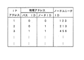
図2に各ノードが備えているアドレスキャッシュテーブルの内容の一例を示す。各ノードは他のノードとの通信の必要性が生ずる度にARPを用いてアドレスキャッシュテーブルを作成する。
【0015】
図3及び図4に、1394バスにのせて実行するARP通信で使われるARPパケットの例を示す。ここで、図3はARPリクエストパケットの例であり、図4はARPレスポンスパケットの例である。これらの図に示すように、ARPリクエストパケット及びARPレスポンスパケットは、1394アシンクロナスパケットヘッダーと、ST(ストリームタイプ)と、LLC/SNAPヘッダーと、ARPパケットから構成されている。そして、ARPパケットは、ARPヘッダーとARPデータから構成されている。以下ARPリクエストパケットとARPレスポンスパケットの内容について順に説明する。
【0016】
ARPリクエストパケットにおける1394アシンクロナスパケットヘッダーの先頭の10ビットには、このパケットが全てのバスに対して送られることを示すブロードキャストバスID(0x3FE)が入っている。そして、次の6ビットにはこのパケットが各バス内の全てのノードに対して送られることを示す値(0x3F)が入っている。先頭から5〜6バイトには、このパケットを送信したノードのノードIDであるソースIDが入っている。さらに次の6バイトには、このパケットを受け取るノードの内部のメモリ空間の所定のアドレスを示すデスティネーションオフセット(0xFFFF FFFF FFFF)が入っている。
【0017】
STフィールドの0x00は、このパケットがLLC(Logical Link Control)通信(ARP/RARP/IP等の通信を含む)に関するパケットであることを意味する。
【0018】
ARPヘッダーのプロトコルタイプフィールドにはこのパケットがIPプロトコルに関するものであることを示す値(0x0800)が入っており、オペレーションフィールドにはARPリクエストであることを示す値が入っている。
【0019】
ARPデータの先頭の8バイトには、ARPリクエストパケットを送信したノードの64ビットアドレスが入っている。この64ビットのうち16ビットはノードID(=ソースID)であり、残りの48ビットはノードの内部のメモリ空間のオフセットアドレスである。このオフセットアドレスは、IPプロトコルを処理するアプリケーションが管理するメモリ空間の先頭アドレス(以下単にアプリケーションのオフセットアドレスという)である。
【0020】
ARPデータの次の8バイトには、このパケットを送信したノードのノードユニークIDが入っている。そして、次の4バイトにはこのノードのIPアドレスが入っている。
【0021】
さらに、次の8バイトはこのパケットの送信先ノードの64ビットアドレスを入れるフィールドであるが、ARPリクエストパケットの場合には、パケットを全てのノードにブロードキャストするので、ここは不確定である(全て1を入れる)。これに続く8バイトのノードユニークIDについても同様である。
【0022】
ARPレスポンスパケットにおける1394アシンクロナスパケットヘッダーの先頭の2バイトであるデスティネーションIDには、このパケットの送信先のノードID、すなわちARPリクエストパケットを送信したノードのノードIDが入っている。次の2バイトのソースIDには、ARPレスポンスパケットを送信したノードのノードIDが入っており、その次の6バイトには、このパケットの受信の際のノードの内部のメモリ空間のオフセットアドレスであるデスティネーションオフセットの値が入っている。このオフセットアドレスは、IPプロトコルを処理するアプリケーションのオフセットアドレスである。ARPリクエストパケット内の“送信元ノードの64ビットアドレス”フィールドの値が入れられる。
【0023】
ARPデータの先頭の8バイトには、ARPレスポンスパケットを送信したノードの64ビットアドレスが入っている。この64ビットのうち16ビットはノードID(=ソースID)であり、残りの48ビットはノードの内部でIPプロトコルを処理するアプリケーションのオフセットアドレスである。
【0024】
ARPデータの次の8バイトには、このパケットを送信したノードのノードユニークIDが入っている。そして、次の4バイトにはこのノードのIPアドレスが入っている。
【0025】
さらに、次の8バイトには、このARPレスポンスパケットの送信先のノード(=ARPリクエストパケットの送信元のノード)の64ビットアドレスが入っている。次の8バイトにはARPレスポンスパケットの送信先のノードユニークIDが入っている。さらに、次の4バイトにはこのノードのIPアドレスが入っている。つまり、この20バイトはARPリクエストパケットのARPデータの先頭の20バイトをスワップしたものである。
【0026】
次に図1〜図4を参照しながらARP通信について説明する。
制御側のノード、例えば第1の1394バス1におけるノード0がIPアドレスが3のノードの物理アドレスを知りたい場合に、図3に示したフォーマットのARPリクエストパケットを第1の1394バス1に送出する。このパケットは第1の1394バス1内の他の全てのノード及び1394ブリッジを介して接続された他の1394バス内の全てのノードで受信される。
【0027】
ARPリクエストパケットを受信したノードは、このパケットのデータ(ST以降)をデスティネーションオフセットが示すアドレスに送り、データの内容を見る。そして、ARPデータにおける送信先のIPアドレスが自分が所有するIPアドレスと一致しなければそのリクエストを無視し、一致する場合には図4に示したARPレスポンスパケットを返信する。図1及び図2の場合、IPアドレスが3のノードは、第2の1394バス2内におけるノードIDが1のノードであるから、このノードがARPレスポンスパケットを返信する。
【0028】
ARPレスポンスパケットを返信するノードは、ARPリクエストパケットのARPヘッダーに書いてあるプロトコルタイプがIPなので、ARPレスポンスパケットの1394アシンクロナスパケットヘッダーのデスティネーションオフセット、及びARPデータの送信元ノードの64ビットアドレスのうちノードIDを除く48ビットには、IPプロトコルを処理するアプリケーションのオフセットアドレスを書く。
【0029】
以上の通信によって、制御側のノードは、指定のIPアドレスのノードについて物理的なノードIDだけでなく、そのノードが備えているアプリケーション(ネットワークプロトコル)のオフセットアドレスについても知ることができる。したがって、上記の通信により以降に制御対象を指定する際、ノードIDに加えて制御対象のノードにおけるアプリケーションのオフセットアドレスを直接指定して送信することができる。制御対象となったノードは、その通信データを受信した際に通信データをオフセットアドレスに転送すればよいので、特にノードが複数のアプリケーションに対応している場合に、CPUがARPヘッダーのプロトコルタイプを見てデータの配分を行うというオーバーヘッドをなくすことができる。
【0030】
また、どんなパケットもCPUを介して固定のオフセットアドレスに配られるようにすると、CPUが通信のために用意する一定の大きさのバッファによって、どんなアプリケーションの通信パケットでも最大長が一定に制限されてしまう。本実施の形態では、こういった問題点に関しても、アプリケーション毎のオフセットアドレスをノードが自由にセットすることで通信データの最大長をフレキシブルに設定することができる。
【0031】
次にバスリセット時の動作について説明する。1394バスにおいては、ノードの電源をオン/オフしたり、バスにノードを接続したり、バスからノードを抜いたりした場合にはバスリセットが起こる。バスリセットが起こると、バスリセットが起きたバス内では自動的にノードIDの割り付けが行われるが、新たに割り付けられたノードIDはバスリセット前のノードIDと異なってしまう可能性がある。また、バスリセットが起きたことは、1394ブリッジを通して他の1394バスに伝達される。したがって、ARPキャッシュテーブルにおいて、バスリセットが起こったバス内のノードに関するデータをエントリー別にフラッシュする。この場合、全てのエントリーをフラッシュしてもよいが、ノードユニークIDはバスリセット後も変化しないので、フラッシュしなくてもよい。ノードユニークIDをフラッシュしない場合には、ノードユニークIDを使用したコマンドセットであれば、アドレス情報が失われても支障なく通信を継続することが可能である。
【0032】
以上ARP通信について説明した。次にRARP通信について説明する。図5及び図6に、1394バスにのせて実行するRARP通信で使われるRARPパケットの例を示す。ここで、図5はRARPリクエストパケットの例であり、図6はRARPレスポンスパケットの例である。RARPパケットの内容はARPパケットの内容と共通する部分が多いので、ここでは異なる部分について説明する。
【0033】
RARPリクエストパケットにおけるLLC/SNAPヘッダーのイーサタイプフィールドには、RARPを示す0X8035を入れる。また、RARPヘッダーのオペレーションフィールドには、RARPリクエストであることを示す値を入れる。RARPデータの送信元ノード(IPアドレスを要請するノード)のIPアドレスを入れるフィールドは不確定であるため全て0を入れる。問合せノードのアドレスはノードユニークIDを用いる。自分のIPアドレスを問合せたい場合は、自分のノードユニークIDを用いる。そして、問合せノードのIPアドレスは不確定であるため全て0にする。
【0034】
RARPレスポンスパケットでは、RARPヘッダーのオペレーションフィールドには、RARPレスポンスであることを示す値を入れる。RARPデータにおける送信元ノードのIPアドレスを入れるフィールドには、サーバーのIPアドレスを入れる。そして、送信先ノードのIPアドレスにはIPアドレスを要請したノードのIPアドレスを入れる。
【0035】
RARP通信では、図5に示したRARPリクエストパケットを1394トランザクションによって1394バス上にブロードキャストで送信し、IPアドレスを知りたいノードのアドレス情報やノードユニークIDを提示してIPアドレスの割当を要請する。サーバーは要請のあったノードにIPアドレスを割り当て、図6に示したRARPレスポンスパケットにのせて返信する。サーバーは、図2と同様のIPアドレスと物理アドレス及びノードユニークIDとの対応テーブルを持っているので、ノードIDだけではなく、ノードユニークIDについても知っている。したがって、バスリセット等が原因で物理的なノードアドレスが不明になった場合でも、確実にIPアドレスを供給することができる。
【0036】
以上、1394バスによるIP通信システムを例にあげて説明をしたが、本発明はIPX通信システムやアップルトーク(Apple Talk)等についても適用できる。また、アドレス長が16バイトのIPバージョン6にも適用できる。
【0037】
【発明の効果】
以上詳細に説明したように、本発明によれば、下記(1)〜(4)の効果を奏する。
【0038】
(1)制御対象のノードにおいてCPUによるデータ分配作業のオーバーヘッドをなくす。
(2)通信時のパケット長についての制限をフレキシブルにする。
(3)バスリセット時の物理ノードアドレス変化に適切に対応する。
(4)バスリセット時に物理ノードアドレスが変化してしまうネットワークにおいてRARP,BCOTP(Bcot Protocol),DHCP(Dynamic Host Configuration Protocol)等を可能とする。
【図面の簡単な説明】
【図1】本発明を適用する通信ネットワークシステムの構成を示す図である。
【図2】アドレスキャッシュテーブルの内容の一例を示す図である。
【図3】ARPリクエストパケットの構成の一例を示す図である。
【図4】ARPレスポンスパケットの構成の一例を示す図である。
【図5】RARPリクエストパケットの構成の一例を示す図である。
【図6】RARPレスポンスパケットの構成の一例を示す図である。
【図7】ARP通信を説明する図である。
【図8】RARP通信を説明する図である。
【符号の説明】
1,2…1394バス、3…1394ブリッジ[0001]
BACKGROUND OF THE INVENTION
The present invention relates to a communication method in which a plurality of electronic devices are connected by, for example, an IEEE-1394 serial bus (hereinafter referred to as 1394 bus) and communication is performed between these electronic devices (hereinafter referred to as nodes). The present invention relates to Address Resolution Protocol) and RARP (Reverse Address Resolution Protocol).
[0002]
[Prior art]
ARP (Address Resolution Protocol) performs communication shown in FIG. That is, the control-side node broadcasts an ARP packet on the bus, and sends a request to notify the node having a specified IP (Internet Protocol) address of the physical address. If the node connected to the bus does not own the specified IP address, the node ignores the request (FIG. 7- [1]), and if it is the node that owns the specified IP address, A physical node address is returned (FIG. 7- [2]).
[0003]
In RARP, the IP address is notified from the RARP server by broadcasting the physical address of the node whose IP address is desired (FIG. 8). In particular, when it is desired to know its own IP address, it broadcasts its own physical node address and informs the RARP server of the IP address.
[0004]
[Problems to be solved by the invention]
Information obtained from the control-side node by the conventional ARP stops at the physical node address of the node to be controlled. For this reason, after the physical node address is determined by ARP, the control-side node transmits communication data to the physical node address of the node to be controlled. As a result, it was necessary to distribute communication data to an appropriate application that can process the protocol. In addition, the maximum length of communicable packets may be limited during this distribution work.
[0005]
Further, in the conventional RARP, when a bus reset occurs during communication, the physical node address of the node that issued the IP address request changes, so the RARP server knows the other party that notifies the IP address by the physical node address. It becomes impossible to do.
[0006]
The present invention has been made in view of such problems, and an object thereof is to provide a communication control method and a node that realize the following (1) to (4).
[0007]
(1) Eliminate the overhead of data distribution work by the CPU in the node to be controlled.
(2) Flexible restriction on packet length during communication.
(3) Appropriately respond to physical node address changes at bus reset.
(4) RARP is enabled in a network in which the physical node address changes upon bus reset.
[0008]
[Means for Solving the Problems]
In order to solve the above-described problems, the present invention provides communication in which a plurality of electronic devices are connected by a communication control bus capable of transmitting control signals and information signals in a mixed manner, and ARP (Address Resolution Protocol) communication is performed between the electronic devices. In the method, the control signal is transmitted from one electronic device to another electronic device, and the control signal specifies electronic device identification information that can uniquely identify the one electronic device and the one electronic device. IP address information, IP address information for specifying the other electronic device, and offset information used for IP communication in the memory in the one electronic device are included.
In order to solve the above problems, the present invention provides a communication control bus that is connected to a plurality of communication control buses capable of transmitting a mixture of control signals and information signals, and performs communication control in the ARP (Address Resolution Protocol) communication electronic device. One electronic device connected to the bus is connected to the electronic device identification information that can uniquely identify the one electronic device, IP address information that identifies the one electronic device, and the communication control bus. Generating means for generating the control signal including IP address information for identifying another electronic device being used, and offset information used for IP communication in a memory in the one electronic device, and the generation Transmission means for transmitting the control signal generated by the means to the other electronic device via the communication control bus.
[0009]
Further, the node unique ID is communicated at the same time, thereby realizing an appropriate response at the time of bus reset.
[0010]
According to the present invention, the communicating node can handle the offset for each application of each node as information in addition to the physical node address. As a result, in subsequent communications, communication data can be directly transferred to the application to be controlled without going through the CPU, and the communication partner can be reliably identified by the node unique ID even when the bus is reset.
[0011]
Further, regarding ARP, the reliability of communication can be improved by flushing the corresponding bus ID entry in the ARP cache table when a bus reset occurs.
[0012]
DETAILED DESCRIPTION OF THE INVENTION
Hereinafter, embodiments of the present invention will be described in detail with reference to the drawings.
FIG. 1 shows a configuration of a communication network system to which the present invention is applied. This communication network system includes a network composed of a first 1394
[0013]
In FIG. 1, a bus ID is assigned to each bus. A node ID (physical node address) is assigned to each node in the bus. This node ID is automatically assigned every time a bus reset occurs, but there is a possibility that it becomes a different value for each bus reset. Further, each node holds a node unique ID defined in IEEE-1394 in the ROM. The node unique ID is an ID unique to each node and does not change even when a bus reset occurs. Each node has the above-described IP address.
[0014]
FIG. 2 shows an example of the contents of the address cache table provided in each node. Each node creates an address cache table using ARP each time communication with another node becomes necessary.
[0015]
3 and 4 show examples of ARP packets used in ARP communication executed on the 1394 bus. Here, FIG. 3 is an example of an ARP request packet, and FIG. 4 is an example of an ARP response packet. As shown in these drawings, the ARP request packet and the ARP response packet are composed of a 1394 asynchronous packet header, an ST (stream type), an LLC / SNAP header, and an ARP packet. The ARP packet is composed of an ARP header and ARP data. Hereinafter, the contents of the ARP request packet and the ARP response packet will be described in order.
[0016]
The first 10 bits of the 1394 asynchronous packet header in the ARP request packet contain a broadcast bus ID (0x3FE) indicating that this packet is sent to all buses. The next 6 bits contain a value (0x3F) indicating that this packet is sent to all nodes in each bus. The source ID, which is the node ID of the node that transmitted this packet, is included in the first 5 to 6 bytes. Further, the next 6 bytes contain a destination offset (0xFFFF FFFF FFFF) indicating a predetermined address in the memory space inside the node receiving this packet.
[0017]
ST field 0x00 means that this packet is a packet related to LLC (Logical Link Control) communication (including communication such as ARP / RARP / IP).
[0018]
The protocol type field of the ARP header contains a value (0x0800) indicating that this packet is related to the IP protocol, and the operation field contains a value indicating that it is an ARP request.
[0019]
The first 8 bytes of the ARP data contain the 64-bit address of the node that transmitted the ARP request packet. Of these 64 bits, 16 bits are a node ID (= source ID), and the remaining 48 bits are an offset address of the memory space inside the node. This offset address is a head address of a memory space managed by an application that processes the IP protocol (hereinafter simply referred to as an application offset address).
[0020]
The next 8 bytes of the ARP data contain the node unique ID of the node that transmitted this packet. The next 4 bytes contain the IP address of this node.
[0021]
Further, the next 8 bytes are a field for storing the 64-bit address of the destination node of this packet. However, in the case of an ARP request packet, the packet is broadcast to all nodes, so this is indeterminate (all 1 ). The same applies to the subsequent 8-byte node unique ID.
[0022]
The destination ID that is the first two bytes of the 1394 asynchronous packet header in the ARP response packet contains the node ID of the destination of the packet, that is, the node ID of the node that transmitted the ARP request packet. The next 2-byte source ID contains the node ID of the node that sent the ARP response packet, and the next 6 bytes contain the offset address of the memory space inside the node when this packet was received. Contains a destination offset value. This offset address is an offset address of an application that processes the IP protocol. The value of the “64-bit address of source node” field in the ARP request packet is entered.
[0023]
The first 8 bytes of the ARP data contain the 64-bit address of the node that transmitted the ARP response packet. Of these 64 bits, 16 bits are a node ID (= source ID), and the remaining 48 bits are an offset address of an application that processes the IP protocol inside the node.
[0024]
The next 8 bytes of the ARP data contain the node unique ID of the node that transmitted this packet. The next 4 bytes contain the IP address of this node.
[0025]
Further, the next 8 bytes contain the 64-bit address of the destination node of the ARP response packet (= the source node of the ARP request packet). The next 8 bytes contain the node unique ID of the destination of the ARP response packet. The next 4 bytes contain the IP address of this node. In other words, these 20 bytes are obtained by swapping the first 20 bytes of the ARP data of the ARP request packet.
[0026]
Next, ARP communication will be described with reference to FIGS.
When the control node, for example, the
[0027]
The node that has received the ARP request packet sends the data (after ST) to the address indicated by the destination offset, and sees the contents of the data. Then, if the IP address of the transmission destination in the ARP data does not match the IP address owned by itself, the request is ignored, and if it matches, the ARP response packet shown in FIG. 4 is returned. In the case of FIGS. 1 and 2, since the node with the
[0028]
Since the node that returns the ARP response packet has the protocol type written in the ARP header of the ARP request packet as IP, the destination offset of the 1394 asynchronous packet header of the ARP response packet and the 64-bit address of the source node of the ARP data Of the 48 bits excluding the node ID, the offset address of the application that processes the IP protocol is written.
[0029]
Through the communication described above, the control-side node can know not only the physical node ID of the node with the specified IP address but also the offset address of the application (network protocol) included in the node. Therefore, when the control target is specified later by the above communication, the offset address of the application in the control target node can be directly specified and transmitted in addition to the node ID. The node to be controlled only has to transfer the communication data to the offset address when the communication data is received, so that the CPU sets the protocol type of the ARP header particularly when the node supports a plurality of applications. It is possible to eliminate the overhead of allocating data by looking.
[0030]
In addition, if any packet is distributed to a fixed offset address via the CPU, the maximum length of any application communication packet is limited to a fixed size by a buffer of a certain size prepared for communication by the CPU. End up. In the present embodiment, the maximum length of the communication data can be set flexibly by setting the offset address for each application freely by the node even with respect to these problems.
[0031]
Next, operation at the time of bus reset will be described. In the 1394 bus, a bus reset occurs when the power of a node is turned on / off, a node is connected to the bus, or a node is removed from the bus. When a bus reset occurs, a node ID is automatically assigned in the bus where the bus reset has occurred, but the newly assigned node ID may be different from the node ID before the bus reset. The occurrence of the bus reset is transmitted to another 1394 bus through the 1394 bridge. Therefore, in the ARP cache table, data relating to the node in the bus where the bus reset has occurred is flushed for each entry. In this case, all entries may be flushed, but the node unique ID does not change even after a bus reset, so it is not necessary to flush. When the node unique ID is not flushed, if the command set uses the node unique ID, the communication can be continued without any trouble even if the address information is lost.
[0032]
The ARP communication has been described above. Next, RARP communication will be described. 5 and 6 show examples of RARP packets used in RARP communication executed on the 1394 bus. Here, FIG. 5 is an example of an RARP request packet, and FIG. 6 is an example of an RARP response packet. Since the contents of the RARP packet have many parts in common with the contents of the ARP packet, different parts will be described here.
[0033]
In the ether type field of the LLC / SNAP header in the RARP request packet, 0X8035 indicating RARP is entered. In the operation field of the RARP header, a value indicating a RARP request is entered. Since the field for entering the IP address of the source node of the RARP data (the node requesting the IP address) is indeterminate, all 0s are entered. The node unique ID is used as the address of the inquiry node. If you want to query your own IP address, use your own node unique ID. Since the IP address of the inquiry node is uncertain, all are set to 0.
[0034]
In the RARP response packet, a value indicating an RARP response is entered in the operation field of the RARP header. In the field for entering the IP address of the transmission source node in the RARP data, the IP address of the server is entered. Then, the IP address of the node that requested the IP address is entered in the IP address of the destination node.
[0035]
In the RARP communication, the RARP request packet shown in FIG. 5 is broadcasted on the 1394 bus by a 1394 transaction, and the address information of the node for which the IP address is desired and the node unique ID are presented to request an IP address assignment. The server assigns an IP address to the requested node, and returns it with the RARP response packet shown in FIG. Since the server has a correspondence table of IP addresses, physical addresses, and node unique IDs as in FIG. 2, it knows not only node IDs but also node unique IDs. Therefore, even when the physical node address is unknown due to a bus reset or the like, the IP address can be reliably supplied.
[0036]
As described above, the IP communication system using the 1394 bus has been described as an example, but the present invention can also be applied to an IPX communication system, Apple Talk, and the like. It can also be applied to
[0037]
【The invention's effect】
As described above in detail, according to the present invention, the following effects (1) to (4) are obtained.
[0038]
(1) Eliminate the overhead of data distribution work by the CPU in the node to be controlled.
(2) Flexible restriction on packet length during communication.
(3) Appropriately respond to physical node address changes at bus reset.
(4) Enables RARP, BCOTP (Bcot Protocol), DHCP (Dynamic Host Configuration Protocol), etc. in a network in which the physical node address changes upon bus reset.
[Brief description of the drawings]
FIG. 1 is a diagram showing a configuration of a communication network system to which the present invention is applied.
FIG. 2 is a diagram illustrating an example of contents of an address cache table.
FIG. 3 is a diagram illustrating an example of a configuration of an ARP request packet.
FIG. 4 is a diagram illustrating an example of a configuration of an ARP response packet.
FIG. 5 is a diagram illustrating an example of a configuration of an RARP request packet.
FIG. 6 is a diagram illustrating an example of a configuration of an RARP response packet.
FIG. 7 is a diagram illustrating ARP communication.
FIG. 8 is a diagram illustrating RARP communication.
[Explanation of symbols]
1,2 ... 1394 bus, 3 ... 1394 bridge
Claims (4)
一の電子機器から他の電子機器に上記制御信号を送信し、
上記制御信号は、上記一の電子機器を固有に識別可能な電子機器識別情報と、上記一の電子機器を特定するIPアドレス情報と、上記他の電子機器を特定するIPアドレス情報と、上記一の電子機器内のメモリにおいてIP通信に利用されるオフセット情報とが含まれていることを特徴とする通信方法。In a communication method in which a plurality of electronic devices are connected by a communication control bus capable of transmitting control signals and information signals mixedly, and ARP (Address Resolution Protocol) communication is performed between the electronic devices.
The above control signal is transmitted from one electronic device to another electronic device,
The control signal includes electronic device identification information that can uniquely identify the one electronic device, IP address information that identifies the one electronic device, IP address information that identifies the other electronic device, and the one And the offset information used for IP communication in the memory in the electronic device.
上記通信制御バス上に接続されている一の電子機器は、
上記一の電子機器を固有に識別可能な電子機器識別情報と、上記一の電子機器を特定するIPアドレス情報と、上記通信制御バス上に接続されている他の電子機器を特定するIPアドレス情報と、上記一の電子機器内のメモリにおいてIP通信に利用されるオフセット情報とが含まれている上記制御信号を生成する生成手段と、
上記生成手段で生成した上記制御信号を上記通信制御バスを介して上記他の電子機器に送信する送信手段とを備えることを特徴とする電子装置。In electronic devices that are connected by a communication control bus that can transmit control signals and information signals mixedly, and that communicate with ARP (Address Resolution Protocol),
One electronic device connected on the communication control bus is
Electronic device identification information that can uniquely identify the one electronic device, IP address information that identifies the one electronic device, and IP address information that identifies another electronic device connected on the communication control bus Generating means for generating the control signal including offset information used for IP communication in a memory in the one electronic device;
An electronic apparatus comprising: a transmission unit configured to transmit the control signal generated by the generation unit to the other electronic device via the communication control bus.
Priority Applications (8)
| Application Number | Priority Date | Filing Date | Title |
|---|---|---|---|
| JP26256896A JP3731263B2 (en) | 1996-09-11 | 1996-09-11 | Communication method and electronic device |
| EP19970307025 EP0833485B1 (en) | 1996-09-11 | 1997-09-10 | Network communication |
| DE1997629040 DE69729040T2 (en) | 1996-09-11 | 1997-09-10 | Network transmission |
| EP20010202939 EP1161058A3 (en) | 1996-09-11 | 1997-09-10 | Network communication |
| KR1019970047769A KR100475776B1 (en) | 1996-09-11 | 1997-09-11 | Network communication system |
| US08/927,625 US5978854A (en) | 1996-09-11 | 1997-09-11 | System using ARP or RARP packet for communicating offset address of an application program and node unique ID of a network node |
| US09/327,891 US6542510B1 (en) | 1996-09-11 | 1999-06-08 | Network communication system |
| US09/328,875 US6438607B1 (en) | 1996-09-11 | 1999-06-08 | System using ARP or RARP packet for communicating offset address of an application program and computer unique ID of a computer |
Applications Claiming Priority (1)
| Application Number | Priority Date | Filing Date | Title |
|---|---|---|---|
| JP26256896A JP3731263B2 (en) | 1996-09-11 | 1996-09-11 | Communication method and electronic device |
Publications (2)
| Publication Number | Publication Date |
|---|---|
| JPH1093597A JPH1093597A (en) | 1998-04-10 |
| JP3731263B2 true JP3731263B2 (en) | 2006-01-05 |
Family
ID=17377616
Family Applications (1)
| Application Number | Title | Priority Date | Filing Date |
|---|---|---|---|
| JP26256896A Expired - Fee Related JP3731263B2 (en) | 1996-09-11 | 1996-09-11 | Communication method and electronic device |
Country Status (5)
| Country | Link |
|---|---|
| US (3) | US5978854A (en) |
| EP (2) | EP0833485B1 (en) |
| JP (1) | JP3731263B2 (en) |
| KR (1) | KR100475776B1 (en) |
| DE (1) | DE69729040T2 (en) |
Families Citing this family (64)
| Publication number | Priority date | Publication date | Assignee | Title |
|---|---|---|---|---|
| JP3731263B2 (en) * | 1996-09-11 | 2006-01-05 | ソニー株式会社 | Communication method and electronic device |
| JPH10229410A (en) * | 1997-02-14 | 1998-08-25 | Canon Inc | Data processor, electronic device, and communication system |
| JP3365262B2 (en) * | 1997-07-14 | 2003-01-08 | 松下電器産業株式会社 | Communication protocol processing device |
| US6418493B1 (en) * | 1997-12-29 | 2002-07-09 | Intel Corporation | Method and apparatus for robust addressing on a dynamically configurable bus |
| JP3277874B2 (en) * | 1998-01-29 | 2002-04-22 | 日本電気株式会社 | IEEE 1394 bridge |
| US6522654B1 (en) * | 1998-05-15 | 2003-02-18 | Harris-Exigent, Inc. | Method for hosting the internet protocol suite on the IEEE-1394 high speed serial bus |
| US6195706B1 (en) * | 1998-07-07 | 2001-02-27 | Emc Corporation | Methods and apparatus for determining, verifying, and rediscovering network IP addresses |
| KR100390397B1 (en) * | 1998-07-13 | 2003-08-19 | 엘지전자 주식회사 | method for transmitting data in internet conncetion device |
| US6496862B1 (en) | 1998-08-25 | 2002-12-17 | Mitsubishi Electric Research Laboratories, Inc. | Remote monitoring and control of devices connected to an IEEE 1394 bus via a gateway device |
| US6505255B1 (en) | 1999-04-29 | 2003-01-07 | Mitsubishi Electric Information Technology Center America, Inc. (Ita) | Method for formatting and routing data between an external network and an internal network |
| US6199112B1 (en) * | 1998-09-23 | 2001-03-06 | Crossroads Systems, Inc. | System and method for resolving fibre channel device addresses on a network using the device's fully qualified domain name |
| US6185631B1 (en) * | 1998-10-14 | 2001-02-06 | International Business Machines Corporation | Program for transferring execution of certain channel functions to a control unit and having means for combining certain commands and data packets in one sequence |
| DE69934192T2 (en) * | 1998-10-27 | 2007-08-30 | Hewlett-Packard Development Co., L.P., Houston | Method and device for network connection by means of bridges |
| JP3543647B2 (en) * | 1998-10-27 | 2004-07-14 | セイコーエプソン株式会社 | Data transfer control device and electronic equipment |
| US6272563B1 (en) * | 1998-11-03 | 2001-08-07 | Intel Corporation | Method and apparatus for communicating routing and attribute information for a transaction between hubs in a computer system |
| US6539450B1 (en) | 1998-11-29 | 2003-03-25 | Sony Corporation | Method and system for adjusting isochronous bandwidths on a bus |
| JP3563990B2 (en) * | 1999-02-24 | 2004-09-08 | キヤノン株式会社 | Network device, network device control method, and recording medium |
| US6374316B1 (en) | 1999-03-19 | 2002-04-16 | Sony Corporation | Method and system for circumscribing a topology to form ring structures |
| US6810452B1 (en) | 1999-03-19 | 2004-10-26 | Sony Corporation | Method and system for quarantine during bus topology configuration |
| US6631415B1 (en) | 1999-03-19 | 2003-10-07 | Sony Corporation | Method and system for providing a communication connection using stream identifiers |
| US6466549B1 (en) * | 1999-04-12 | 2002-10-15 | Intel Corporation | Broadcast discovery in a network having one or more 1394 buses |
| US6502158B1 (en) | 1999-04-23 | 2002-12-31 | Sony Corporation | Method and system for address spaces |
| US6633547B1 (en) | 1999-04-29 | 2003-10-14 | Mitsubishi Electric Research Laboratories, Inc. | Command and control transfer |
| US6378000B1 (en) | 1999-04-29 | 2002-04-23 | Mitsubish Electric Research Laboratories, Inc | Address mapping in home entertainment network |
| US6523064B1 (en) | 1999-04-29 | 2003-02-18 | Mitsubishi Electric Research Laboratories, Inc | Network gateway for collecting geographic data information |
| JP4505692B2 (en) * | 1999-06-18 | 2010-07-21 | ソニー株式会社 | Data communication apparatus and method, and recording medium |
| US6519657B1 (en) | 1999-08-09 | 2003-02-11 | Sony Electronics, Inc. | Method and device for identifying an active 1394A node attached to a 1394B network |
| US6772232B1 (en) * | 1999-08-26 | 2004-08-03 | Hewlett-Packard Development Company, L.P. | Address assignment procedure that enables a device to calculate addresses of neighbor devices |
| JP4536981B2 (en) * | 1999-08-31 | 2010-09-01 | キヤノン株式会社 | Information signal processing apparatus and information signal processing method |
| US6799204B1 (en) * | 1999-10-22 | 2004-09-28 | Telcordia Technologies, Inc. | Method and system for dynamic registration and configuration protocol |
| CN1452741A (en) * | 1999-11-12 | 2003-10-29 | 交叉路径系统公司 | Method and system for mapping addressing of SCSI devices between storage area networks |
| US6848007B1 (en) | 1999-11-12 | 2005-01-25 | Crossroads Systems, Inc. | System for mapping addresses of SCSI devices between plurality of SANs that can dynamically map SCSI device addresses across a SAN extender |
| US6728821B1 (en) | 1999-11-29 | 2004-04-27 | Sony Corporation | Method and system for adjusting isochronous bandwidths on a bus |
| US6697814B1 (en) | 1999-12-04 | 2004-02-24 | Worldcom, Inc. | System for processing records in a communications network |
| US6714978B1 (en) * | 1999-12-04 | 2004-03-30 | Worldcom, Inc. | Method and system for processing records in a communications network |
| US6687355B1 (en) | 1999-12-04 | 2004-02-03 | Worldcom, Inc. | Method and system for processing records in a communications network |
| US6771649B1 (en) * | 1999-12-06 | 2004-08-03 | At&T Corp. | Middle approach to asynchronous and backward-compatible detection and prevention of ARP cache poisoning |
| US6295276B1 (en) * | 1999-12-31 | 2001-09-25 | Ragula Systems | Combining routers to increase concurrency and redundancy in external network access |
| US6493341B1 (en) | 1999-12-31 | 2002-12-10 | Ragula Systems | Combining routers to increase concurrency and redundancy in external network access |
| JP2001251375A (en) | 2000-03-06 | 2001-09-14 | Sony Corp | Transmission method, transmission system, input device, output device and transmission controller |
| US6647446B1 (en) * | 2000-03-18 | 2003-11-11 | Sony Corporation | Method and system for using a new bus identifier resulting from a bus topology change |
| US6795403B1 (en) * | 2000-03-31 | 2004-09-21 | Cisco Technology, Inc. | Automatic discovery of switch devices in a network |
| US6782436B1 (en) * | 2000-04-21 | 2004-08-24 | Richard A. Baker | Method and apparatus for locating devices within a network system |
| US6757773B1 (en) | 2000-06-30 | 2004-06-29 | Sony Corporation | System and method for determining support capability of a device coupled to a bus system |
| US6993022B1 (en) * | 2000-07-06 | 2006-01-31 | Sony Corporation | Method of and apparatus for directly mapping communications through a router between nodes on different buses within a network of buses |
| NL1016338C2 (en) * | 2000-10-05 | 2002-04-11 | Roelof Reinders | Method for assigning an identification code to nodes in a network, communicating in a network, and controlling a network. |
| US6968242B1 (en) * | 2000-11-07 | 2005-11-22 | Schneider Automation Inc. | Method and apparatus for an active standby control system on a network |
| US7023795B1 (en) * | 2000-11-07 | 2006-04-04 | Schneider Automation Inc. | Method and apparatus for an active standby control system on a network |
| JP2002190816A (en) * | 2000-12-20 | 2002-07-05 | Nec Corp | Wireless communication system |
| CN1146270C (en) * | 2001-06-27 | 2004-04-14 | 华为技术有限公司 | Method for automatically obtaining IP address of equipment |
| JP3590387B2 (en) * | 2001-11-01 | 2004-11-17 | 株式会社東芝 | Communication device and program |
| JP3885585B2 (en) * | 2001-12-28 | 2007-02-21 | 松下電器産業株式会社 | Router device and network system using the same |
| KR100779325B1 (en) * | 2002-02-22 | 2007-11-23 | 엘지노텔 주식회사 | Method for obtaining MAC Address using Mobile ARP cache in Mobile IP Network |
| US20040083293A1 (en) * | 2002-02-25 | 2004-04-29 | Dong Chen | Ethernet addressing via physical location for massively parallel systems |
| US7016328B2 (en) * | 2003-06-24 | 2006-03-21 | Tropos Networks, Inc. | Method for allowing a client to access a wireless system |
| US7649866B2 (en) * | 2003-06-24 | 2010-01-19 | Tropos Networks, Inc. | Method of subnet roaming within a network |
| JP4174392B2 (en) * | 2003-08-28 | 2008-10-29 | 日本電気株式会社 | Network unauthorized connection prevention system and network unauthorized connection prevention device |
| KR100432675B1 (en) * | 2003-09-19 | 2004-05-27 | 주식회사 아이앤아이맥스 | Method of controlling communication between equipments on a network and apparatus for the same |
| US7555569B1 (en) * | 2004-02-02 | 2009-06-30 | Emc Corporation | Quick configuration status |
| EP1797512B1 (en) * | 2004-10-05 | 2010-09-08 | Mentor Graphics Corporation | Accelerated hardware emulation environment for processor-based systems |
| US20060268851A1 (en) * | 2005-05-10 | 2006-11-30 | International Business Machines Corporation | Method and apparatus for address resolution protocol persistent in a network data processing system |
| KR101124748B1 (en) * | 2005-05-27 | 2012-03-23 | 엘지전자 주식회사 | Apparatus for establishing network and Method thereof |
| US20060274752A1 (en) * | 2005-06-06 | 2006-12-07 | Vinit Jain | Method and apparatus for managing address resolution protocol data for interfaces connected to different switches |
| US8953617B2 (en) | 2013-01-11 | 2015-02-10 | Dell Products, Lp | System and method for utilizing a unique identifier while registering a device in a network |
Family Cites Families (27)
| Publication number | Priority date | Publication date | Assignee | Title |
|---|---|---|---|---|
| US4953072A (en) * | 1987-05-01 | 1990-08-28 | Digital Equipment Corporation | Node for servicing interrupt request messages on a pended bus |
| US5490258A (en) * | 1991-07-29 | 1996-02-06 | Fenner; Peter R. | Associative memory for very large key spaces |
| US5123089A (en) * | 1989-06-19 | 1992-06-16 | Applied Creative Technology, Inc. | Apparatus and protocol for local area network |
| US5175822A (en) * | 1989-06-19 | 1992-12-29 | International Business Machines Corporation | Apparatus and method for assigning addresses to scsi supported peripheral devices |
| US5282270A (en) * | 1990-06-06 | 1994-01-25 | Apple Computer, Inc. | Network device location using multicast |
| CA2048306A1 (en) * | 1990-10-02 | 1992-04-03 | Steven P. Miller | Distributed configuration profile for computing system |
| US5287103A (en) * | 1991-12-30 | 1994-02-15 | At&T Bell Laboratories | Method and apparatus for providing local area network clients with internetwork identification data |
| US5526489A (en) * | 1993-03-19 | 1996-06-11 | 3Com Corporation | System for reverse address resolution for remote network device independent of its physical address |
| JPH07245619A (en) * | 1994-03-03 | 1995-09-19 | Hitachi Ltd | Control method for lan system |
| US5632016A (en) * | 1994-09-27 | 1997-05-20 | International Business Machines Corporation | System for reformatting a response packet with speed code from a source packet using DMA engine to retrieve count field and address from source packet |
| US5815678A (en) * | 1995-07-14 | 1998-09-29 | Adaptec, Inc. | Method and apparatus for implementing an application programming interface for a communications bus |
| US5666362A (en) * | 1995-07-25 | 1997-09-09 | 3Com Corporation | Method and apparatus for asynchronous PPP and synchronous PPP conversion |
| US5790554A (en) * | 1995-10-04 | 1998-08-04 | Bay Networks, Inc. | Method and apparatus for processing data packets in a network |
| KR0154016B1 (en) * | 1995-10-31 | 1998-11-16 | 배순훈 | Method for searching atm address of destination lan emulation client by using lan-arp cache in lan emulation client |
| JPH09162887A (en) * | 1995-12-08 | 1997-06-20 | Hitachi Ltd | Terminal connection method on network and network system |
| US5764930A (en) * | 1996-04-01 | 1998-06-09 | Apple Computer, Inc. | Method and apparatus for providing reset transparency on a reconfigurable bus |
| US5935267A (en) * | 1996-04-12 | 1999-08-10 | Fuji Photo Film Co., Ltd. | Data communication method and a data communication system for use with a digital network |
| US5802055A (en) * | 1996-04-22 | 1998-09-01 | Apple Computer, Inc. | Method and apparatus for dynamic buffer allocation in a bus bridge for pipelined reads |
| US5835720A (en) * | 1996-05-17 | 1998-11-10 | Sun Microsystems, Inc. | IP discovery apparatus and method |
| US5799002A (en) * | 1996-07-02 | 1998-08-25 | Microsoft Corporation | Adaptive bandwidth throttling for network services |
| US5872847A (en) * | 1996-07-30 | 1999-02-16 | Itt Industries, Inc. | Using trusted associations to establish trust in a computer network |
| JP3731263B2 (en) * | 1996-09-11 | 2006-01-05 | ソニー株式会社 | Communication method and electronic device |
| US5915119A (en) * | 1996-10-01 | 1999-06-22 | Ncr Corporation | Proxy terminal for network controlling of power managed user terminals in suspend mode |
| US6101543A (en) * | 1996-10-25 | 2000-08-08 | Digital Equipment Corporation | Pseudo network adapter for frame capture, encapsulation and encryption |
| US6131119A (en) * | 1997-04-01 | 2000-10-10 | Sony Corporation | Automatic configuration system for mapping node addresses within a bus structure to their physical location |
| JP3028783B2 (en) * | 1997-04-25 | 2000-04-04 | 日本電気株式会社 | Network monitoring method and device |
| US6298409B1 (en) * | 1998-03-26 | 2001-10-02 | Micron Technology, Inc. | System for data and interrupt posting for computer devices |
-
1996
- 1996-09-11 JP JP26256896A patent/JP3731263B2/en not_active Expired - Fee Related
-
1997
- 1997-09-10 EP EP19970307025 patent/EP0833485B1/en not_active Expired - Lifetime
- 1997-09-10 EP EP20010202939 patent/EP1161058A3/en not_active Withdrawn
- 1997-09-10 DE DE1997629040 patent/DE69729040T2/en not_active Expired - Lifetime
- 1997-09-11 KR KR1019970047769A patent/KR100475776B1/en not_active IP Right Cessation
- 1997-09-11 US US08/927,625 patent/US5978854A/en not_active Expired - Lifetime
-
1999
- 1999-06-08 US US09/327,891 patent/US6542510B1/en not_active Expired - Lifetime
- 1999-06-08 US US09/328,875 patent/US6438607B1/en not_active Expired - Lifetime
Also Published As
| Publication number | Publication date |
|---|---|
| US6438607B1 (en) | 2002-08-20 |
| EP0833485B1 (en) | 2004-05-12 |
| JPH1093597A (en) | 1998-04-10 |
| KR100475776B1 (en) | 2005-07-28 |
| EP0833485A1 (en) | 1998-04-01 |
| KR19980024775A (en) | 1998-07-06 |
| DE69729040T2 (en) | 2005-04-28 |
| US6542510B1 (en) | 2003-04-01 |
| EP1161058A3 (en) | 2003-12-03 |
| US5978854A (en) | 1999-11-02 |
| EP1161058A2 (en) | 2001-12-05 |
| DE69729040D1 (en) | 2004-06-17 |
Similar Documents
| Publication | Publication Date | Title |
|---|---|---|
| JP3731263B2 (en) | Communication method and electronic device | |
| JP3828894B2 (en) | IPv4-to-IPv6 conversion apparatus and method using dual stack | |
| US7339895B2 (en) | Gateway device and control method for communication with IP and IPV6 protocols | |
| US7352726B2 (en) | Communication device, communication method and program for packet communications between two networks that conform to different standards | |
| US6445711B1 (en) | Method of and apparatus for implementing and sending an asynchronous control mechanism packet used to control bridge devices within a network of IEEE STD 1394 serial buses | |
| JP3876732B2 (en) | Gateway device, gateway device address management method, and AV device having gateway function | |
| US7046666B1 (en) | Method and apparatus for communicating between divergent networks using media access control communications | |
| US8028035B2 (en) | Shared resource support for internet protocols | |
| JP2853662B2 (en) | Mobile host compatible network | |
| US6128294A (en) | Network connecting apparatus | |
| KR100538223B1 (en) | System and method for deleting tunnelling in the connection between mobile node and correspondent node | |
| KR100484145B1 (en) | Apparatus and method for automatically allocating virtual address to duplicate addressed nodes | |
| KR20040065643A (en) | Method for performing automatic registration of IP address and IP domain name in IP protocol version 6 | |
| JP2001244976A (en) | Device and system for multicast packet transfer and storage medium | |
| JP2003204345A (en) | Communication system, packet repeating apparatus, method for repeating packet and repeating program | |
| GB2283645A (en) | Digital communication systems | |
| Johansson | IPv4 over IEEE 1394 | |
| JPH10136052A (en) | Ipv4-ipv6 communication method and ipv4-ipv6 conversion device | |
| JP2001308909A (en) | Method for assigning logical network address and terminal | |
| Cisco | SMDS Commands | |
| Cisco | SMDS Commands | |
| JP3156231B2 (en) | Address resolution server | |
| JPH1155319A (en) | Ipv4-ipv6 communication method and conversion device therefor | |
| JP3604032B2 (en) | IEEE 1394-Ethernet bridge node and method | |
| JPH11136285A (en) | Ipv4-ipv6 communication method and ipv4-ipv6 converter |
Legal Events
| Date | Code | Title | Description |
|---|---|---|---|
| A977 | Report on retrieval |
Free format text: JAPANESE INTERMEDIATE CODE: A971007 Effective date: 20050914 |
|
| TRDD | Decision of grant or rejection written | ||
| A01 | Written decision to grant a patent or to grant a registration (utility model) |
Free format text: JAPANESE INTERMEDIATE CODE: A01 Effective date: 20050920 |
|
| A61 | First payment of annual fees (during grant procedure) |
Free format text: JAPANESE INTERMEDIATE CODE: A61 Effective date: 20051003 |
|
| FPAY | Renewal fee payment (event date is renewal date of database) |
Free format text: PAYMENT UNTIL: 20091021 Year of fee payment: 4 |
|
| FPAY | Renewal fee payment (event date is renewal date of database) |
Free format text: PAYMENT UNTIL: 20091021 Year of fee payment: 4 |
|
| FPAY | Renewal fee payment (event date is renewal date of database) |
Free format text: PAYMENT UNTIL: 20101021 Year of fee payment: 5 |
|
| FPAY | Renewal fee payment (event date is renewal date of database) |
Free format text: PAYMENT UNTIL: 20111021 Year of fee payment: 6 |
|
| FPAY | Renewal fee payment (event date is renewal date of database) |
Free format text: PAYMENT UNTIL: 20121021 Year of fee payment: 7 |
|
| FPAY | Renewal fee payment (event date is renewal date of database) |
Free format text: PAYMENT UNTIL: 20131021 Year of fee payment: 8 |
|
| R250 | Receipt of annual fees |
Free format text: JAPANESE INTERMEDIATE CODE: R250 |
|
| LAPS | Cancellation because of no payment of annual fees |