JP3729252B2 - Image processing system, program, and information storage medium - Google Patents
Image processing system, program, and information storage medium Download PDFInfo
- Publication number
- JP3729252B2 JP3729252B2 JP2001086778A JP2001086778A JP3729252B2 JP 3729252 B2 JP3729252 B2 JP 3729252B2 JP 2001086778 A JP2001086778 A JP 2001086778A JP 2001086778 A JP2001086778 A JP 2001086778A JP 3729252 B2 JP3729252 B2 JP 3729252B2
- Authority
- JP
- Japan
- Prior art keywords
- color conversion
- image
- data
- image signal
- signal values
- Prior art date
- Legal status (The legal status is an assumption and is not a legal conclusion. Google has not performed a legal analysis and makes no representation as to the accuracy of the status listed.)
- Expired - Fee Related
Links
- 238000012545 processing Methods 0.000 title claims description 51
- 238000006243 chemical reaction Methods 0.000 claims description 152
- 230000000007 visual effect Effects 0.000 claims description 16
- 230000006870 function Effects 0.000 claims description 10
- 238000013507 mapping Methods 0.000 claims 1
- 238000004364 calculation method Methods 0.000 description 22
- 238000010586 diagram Methods 0.000 description 10
- 238000000034 method Methods 0.000 description 9
- 239000003086 colorant Substances 0.000 description 8
- 238000013500 data storage Methods 0.000 description 8
- 230000010354 integration Effects 0.000 description 7
- 239000004973 liquid crystal related substance Substances 0.000 description 6
- 230000007274 generation of a signal involved in cell-cell signaling Effects 0.000 description 4
- 238000007781 pre-processing Methods 0.000 description 4
- 230000005540 biological transmission Effects 0.000 description 3
- 238000007796 conventional method Methods 0.000 description 2
- 241001085205 Prenanthella exigua Species 0.000 description 1
- 238000004422 calculation algorithm Methods 0.000 description 1
- 238000013075 data extraction Methods 0.000 description 1
- 238000013461 design Methods 0.000 description 1
- 230000000694 effects Effects 0.000 description 1
- 238000005401 electroluminescence Methods 0.000 description 1
- 230000007613 environmental effect Effects 0.000 description 1
- 239000000284 extract Substances 0.000 description 1
- 238000000605 extraction Methods 0.000 description 1
- 238000003384 imaging method Methods 0.000 description 1
- 238000012986 modification Methods 0.000 description 1
- 230000004048 modification Effects 0.000 description 1
Images


Classifications
-
- H—ELECTRICITY
- H04—ELECTRIC COMMUNICATION TECHNIQUE
- H04N—PICTORIAL COMMUNICATION, e.g. TELEVISION
- H04N9/00—Details of colour television systems
- H04N9/64—Circuits for processing colour signals
- H04N9/73—Colour balance circuits, e.g. white balance circuits or colour temperature control
-
- H—ELECTRICITY
- H04—ELECTRIC COMMUNICATION TECHNIQUE
- H04N—PICTORIAL COMMUNICATION, e.g. TELEVISION
- H04N9/00—Details of colour television systems
- H04N9/64—Circuits for processing colour signals
- H04N9/641—Multi-purpose receivers, e.g. for auxiliary information
Landscapes
- Engineering & Computer Science (AREA)
- Multimedia (AREA)
- Signal Processing (AREA)
- Color Image Communication Systems (AREA)
- Image Processing (AREA)
- Facsimile Image Signal Circuits (AREA)
- Testing, Inspecting, Measuring Of Stereoscopic Televisions And Televisions (AREA)
- Processing Of Color Television Signals (AREA)
- Controls And Circuits For Display Device (AREA)
Description
【0001】
【発明の属する技術分野】
本発明は、目標色を再現するために画像データの変換を行う画像処理システム、プログラムおよび情報記憶媒体に関する。
【0002】
【背景技術および発明が解決しようとする課題】
一般に、目標色(例えばsRGB等の規格に適合した色等)を再現するために画像データの色変換を行う場合、3次元ルックアップテーブル(以下、「3D−LUT」という。)と補間演算を組み合わせて色の変換が行われている。
【0003】
全ての画像信号(例えば、R信号、G信号、B信号等)の組み合わせを3D−LUTで表現する手法も考えられるが、3色8ビットのシステムでは50MB(メガバイト)程度になり、多大な記憶容量が必要となる(洪博哲著『お話・カラー画像処理』CQ出版株式会社、1999年発行、123ページ参照)。
【0004】
また、補間演算を行う場合、8点を用いて補間演算を行うが、この手法では多大な演算時間がかかってしまう。
【0005】
演算時間を短縮するため、3D−LUT空間における対象点を含む立方体を分割して対象点を含む三角錐を用いて、すなわち、4点を用いて補間演算する手法も提案されている(同書参照)。
【0006】
しかし、この4点の抽出や補間演算自体が複雑であり、演算時間がかかってしまう。
【0007】
特に、動画像のように60分の1秒でリアルタイムに画像を書き換える場合には、色変換にかかる演算時間を短縮することが重要となる。
【0008】
本発明は、上記の課題に鑑みなされたものであり、その目的は、目標色を再現するために画像データの変換を行う場合に、より少ない記憶容量で、かつ、より少ない演算時間で色変換を行うことのできる画像処理システム、プログラムおよび情報記憶媒体を提供することにある。
【0009】
【課題を解決するための手段】
上記課題を解決するため、本発明に係る画像処理システムは、目標色を再現するために、複数種の画像信号値によって表現される画像データの変換を行う画像処理システムにおいて、
所定の色変換用データに基づき、前記画像データを変換する色変換手段を含み、
前記色変換用データは、前記画像信号値の種別ごとに、色変換後の画像信号値を、色変換前の複数種の画像信号値と対応付けるための信号別対応付けデータを含み、
前記色変換手段は、
入力される画像信号値と、前記信号別対応付けデータと、に基づき、前記画像信号値の種別ごとに、画像信号値の色変換を行う手段と、
色変換の行われた画像信号値を、前記画像信号値の種別ごとに統合する手段と、
を含むことを特徴とする。
【0010】
また、本発明に係るプログラムは、目標色を再現するために、複数種の画像信号値によって表現される画像データの変換を行うためのプログラムであり、コンピュータにより読み取り可能なプログラムであって、
所定の色変換用データに基づき、前記画像データを変換する色変換手段としてコンピュータを機能させ、
前記色変換用データは、前記画像信号値の種別ごとに、色変換後の画像信号値を、色変換前の複数種の画像信号値と対応付けるための信号別対応付けデータを含み、
前記色変換手段は、
入力される画像信号値と、前記信号別対応付けデータと、に基づき、前記画像信号値の種別ごとに、画像信号値の色変換を行う手段と、
色変換の行われた画像信号値を、前記画像信号値の種別ごとに統合する手段と、
を含むことを特徴とする。
【0011】
また、本発明に係る情報記憶媒体は、コンピュータにより読み取り可能な情報記憶媒体であって、上記手段をコンピュータに実現させるためのプログラムを記憶したことを特徴とする。
【0012】
本発明によれば、画像信号値の種別ごとに、前記複数種の画像信号値で表される画像信号値を求め、求められた画像信号値を画像信号値の種別ごとに統合することにより、目的とする画像信号値を得ることができる。
【0013】
これにより、色変換用データのために必要となる記憶容量を低減し、色変換にかかる演算時間を短縮できる。
【0014】
すなわち、例えば、上述したように、3色8ビットで構成される3D−LUTの場合、50MB程度が必要となる。一方、本発明によれば、24ビット×256×3色=2304B(バイト)で済む。
【0015】
また、色変換時の演算のアルゴリズムも、統合、すなわち、信号別対応付けデータの検索と、和算だけで済むので、線形補間等を用いる従来の手法に比べて演算時間を低減できる。
【0016】
また、前記画像処理システムは、所定の状況において、前記目標色に応じて前記色変換用データを生成する色変換用データ生成手段を含んでもよい。
【0017】
また、前記プログラムは、所定の状況において、前記目標色に応じて前記色変換用データを生成する色変換用データ生成手段としてコンピュータを機能させてもよい。
【0018】
また、前記情報記憶媒体は、前記色変換用データ生成手段としてコンピュータを機能させるプログラムを記憶してもよい。
【0019】
これによれば、色変換用データを柔軟に生成することができるため、種々の目標色に対応した色変換を行うことができる。
【0020】
また、前記画像処理システム、前記プログラムおよび前記情報記憶媒体において、前記信号別対応付けデータは、前記複数種の画像信号値を比率で表現したものであってもよい。
【0021】
これによれば、比率で表現することにより、必要となる記憶容量をさらに低減させることができる。すなわち、再現しようとする色は同じであるため、階調によらず、各画像信号値間の比率は一定である。例えば、3色(3種類の信号値)の場合、9つのデータで済む。
【0022】
また、前記画像処理システム、前記プログラムおよび前記情報記憶媒体において、前記画像データは、動画像データであってもよい。
【0023】
これによれば、リアルタイムに色変換を行えるため、動画像データの色変換も快適に行うことができる。
【0024】
また、前記画像処理システム、前記プログラムおよび前記情報記憶媒体において、前記色変換用データ生成手段は、視環境を示す環境情報に基づき、前記色変換用データを生成してもよい。
【0025】
これによれば、視環境によって目標色が変更される場合であっても、視環境に応じた色変換を行うことができる。
【0026】
また、前記画像処理システム、前記プログラムおよび前記情報記憶媒体において、前記色変換用データ生成手段は、画像の校正時に、前記色変換用データを生成してもよい。
【0027】
これによれば、画像の校正時に色変換用データを生成することにより、校正の指示に応じた正確な色変換用データを生成することができる。
【0028】
【発明の実施の形態】
以下、本発明を、動画像を投写表示する液晶プロジェクタを用いた画像処理システムに適用した場合を例に採り、図面を参照しつつ説明する。
【0029】
(システム全体の説明)
図1は、本実施の形態の一例に係る画像処理システムの概略説明図である。
【0030】
スクリーン10のほぼ正面に設けられた投写型表示装置の一種であるプロジェクタ20から、所定のプレゼンテーション用の動画像や静止画像が投写される。プレゼンター30は、スクリーン10上の被表示領域である画像表示領域12の画像の所望の位置をレーザーポインタ50から投射したスポット光70で指し示しながら、第三者に対するプレゼンテーションを行う。
【0031】
このようなプレゼンテーションを行う場合、スクリーン10の種別や、環境光80によって画像表示領域12の画像の見え方は大きく異なってしまう。例えば、同じ白を表示する場合であっても、スクリーン10の種別によっては、黄色がかった白に見えたり、青色がかった白に見えたりする。また、同じ白を表示する場合であっても、環境光80が異なれば、明るい白に見えたり、暗い白に見えたりする。
【0032】
また、近年、プロジェクタ20は小型化が進み、持ち運びも容易になっている。このため、例えば、客先においてプレゼンテーションを行う場合もあり得るが、客先の環境に合わせて色を事前に調整することは困難であり、客先で色を手動で調整するには時間がかかりすぎる。
【0033】
従来のプロジェクタでは、プロジェクタ固有の入出力特性を示す入出力用プロファイルに基づき、色の変換を行っているだけであり、画像の投写表示される視環境は考慮されていない。なお、プロファイルとは、特性データという意味である。
【0034】
しかし、上述したように、視環境を考慮しなければ、画像の色の見え方を統一することは困難である。色の見え方は、光、対象の光の反射または透過、視覚の3つの要因で決定する。
【0035】
本実施の形態では、光および対象の光の反射または透過を反映した視環境を把握することにより、適切な画像の色を再現できる画像処理システムを実現している。
【0036】
ところで、このような画像の表示を行う場合、sRGB等の規格に準拠した色を目標色として、目標色を画像処理システムが適用される視環境において適切に再現するために画像の色の変換を行う。
【0037】
しかし、従来の手法では、画像の色の変換には、3D−LUTのための多大な記憶容量が必要だったり、補間演算のために多大な演算時間がかかっていた。
【0038】
図2は、従来のプロジェクタ内のプロジェクタ画像処理部100の機能ブロックの一例を示す図である。
【0039】
プロジェクタでは、PC等から送られるアナログ形式のRGB信号を構成するR1信号、G1信号、B1信号をA/D変換部110に入力し、デジタル形式のR2信号値、G2信号値、B2信号値を、CPU200によって制御されるプロジェクタ画像処理部100で色変換およびガンマ処理を行っている。
【0040】
そして、色変換されたR3信号値、G3信号値、B3信号値をガンマ処理してR4信号値、G4信号値、B4信号値となった各画像信号値をD/A変換部180に入力し、アナログ変換されたR5信号、G5信号、B5信号を、画像表示手段の一部であるL/V(ライトバルブ)駆動部190に入力し、液晶ライトバルブを駆動して画像の投写表示を行っている。
【0041】
プロジェクタ画像処理部100は、プロジェクタ色変換部120と、ガンマ処理部170と、色域演算部160と、キャリブレーション信号発生部150とを含んで構成されている。
【0042】
キャリブレーション信号発生部150は、キャリブレーション(校正用)画像信号値を生成する。このキャリブレーション画像信号は、A/D変換部110から出力される信号値と同様に、デジタル形式のR2信号値、G2信号値、B2信号値としてプロジェクタ色変換部120に入力される。
【0043】
このように、キャリブレーション画像信号値をプロジェクタ20の内部で生成するため、PC等の外部入力装置からキャリブレーション画像信号値をプロジェクタ20に入力することなく、プロジェクタ20単体でキャリブレーションを行うことができる。
【0044】
プロジェクタ色変換部120は、キャリブレーション信号発生部150からのRGBの各デジタル信号値(R2、G2、B2)を、プロジェクタプロファイル記憶部164が管理しているプロジェクタプロファイルを参照し、プロジェクタ出力に適したRGBデジタル信号値(R3、G3、B3)に変換する。
【0045】
また、プロジェクタ色変換部120は、各デジタル信号値(R2、G2、B2)を変換するための3D−LUTを生成する3D−LUT生成部122と、生成された3D−LUTを記憶する3D−LUT記憶部124とを含んで構成されている。
【0046】
3D−LUT生成部122は、より具体的には、色域演算部160で演算された色域を再現できるように3D−LUTを生成する。
【0047】
次に、色域演算部160について説明する。
【0048】
また、色域演算部160は、目標プロファイル記憶部162と、プロジェクタプロファイル記憶部164とを含んで構成されている。より具体的には、色域演算部160は、目標プロファイル、色光センサー60からの環境情報、プロジェクタプロファイルに基づき、ユーザーが選択した好みの色であって、かつ、視環境に適合した画像の色の見え方になるように、色域を演算する。
【0049】
なお、ここで、目標プロファイルとは、目標とすべき色(ここでは、sRGB規格における色)の入出力特性データの一種である。また、プロジェクタプロファイルとは、プロジェクタの機種に対応した入出力特性データの一種である。
【0050】
また、ガンマ処理部170は、プロジェクタ色変換部120によって色変換された各画像信号(R3信号、G3信号、B3信号)に対してガンマ処理を行う。
【0051】
このように、従来は、3D−LUTを用いて色変換を行っていたため、3D−LUT記憶部124に記憶される3D−LUTの容量が過大となっていた。また、視環境が変わる度に新たに3D−LUTを生成する必要がある上、補間も必要であり、色変換に時間がかかっていた。
【0052】
特に、本実施形態のように、動画像を表示する場合、色変換に時間がかかるとリアルタイムな動画像表示を行うことができなくなる。
【0053】
本実施の形態では、3D−LUTに代わる色変換用データとして、画像信号値の種別ごとに、色変換後の画像信号値を、色変換前の複数種の画像信号値と対応付けるための信号別対応付けデータを用いる。そして、この信号別対応付けデータを用いて色変換を行い、色変換の行われた画像信号値を、画像信号値の種別ごとに統合する。
【0054】
これにより、色変換用データのために必要となる記憶容量を低減し、色変換にかかる演算時間を短縮できる。
【0055】
次に、本実施形態の一例に係るプロジェクタ20内のプロジェクタ画像処理部100の機能ブロックについて説明する。
【0056】
図3は、本実施形態の一例に係るプロジェクタ20内のプロジェクタ画像処理部100の機能ブロック図である。
【0057】
図2に示すプロジェクタ画像処理部100との違いは、色域演算部160によって求められた色域に基づいて色を変換するための変換用データを生成する変換用データ生成部130と、生成された変換用データを記憶する変換用データ記憶部123と、入力される画像信号値と、信号別対応付けデータとに基づき、画像信号値の種別ごとに、画像信号値の色変換を行う変換部125と、変換された画像信号値を画像信号値の種別ごとに統合する統合部127とを設けていることである。
【0058】
なお、変換用データ記憶部123、変換部125および統合部127は、プロジェクタ色変換部121に含まれる。
【0059】
図4は、本実施形態の一例に係る変換用データを示す模式図である。
【0060】
本実施の形態では、RGB信号値を用いているため、R信号値、G信号値、B信号値のそれぞれに、信号別対応付けデータが設けられている。なお、ここで、信号別対応付けデータは、色変換前のR信号値、G信号値およびB信号値で表される。
【0061】
具体的には、例えば、R信号値、G信号値、B信号値のそれぞれの値が255、255、255である場合、すなわち、白である場合、色変換後のR信号値は、(R、G、B)=(250、0、8)で表され、色変換後のG信号値は、(R、G、B)=(5、189、15)で表され、色変換後のB信号値は、(R、G、B)=(0、12、196)で表される。
【0062】
なお、このように、もともと1つの画像信号値だけで表されるものを、3つの画像信号値で表す必要があるのは、視環境によって目標色を再現するための色域が標準的な色域とは異なり、色域のずれが生じているからである。例えば、標準的な環境では赤のRGB信号値は(R、G、B)=(255、0、0)であるが、視環境が異なれば、赤であってもR信号値だけでは表すことができず、R、G、Bの全ての信号値を用いて表す必要がある。
【0063】
また、統合部127は、変換部125によって変換されたR、G、Bの各画像信号値の和を演算する。上述した白を再現する場合、RGB信号値は、(R、G、B)=(255、201、219)で表される。
【0064】
なお、図4に示す具体的な数値は、あくまで一例であり、プロジェクタ20等のデバイスや、視環境によって変わるものである。
【0065】
次に、図3に示す各部を用いた処理の流れについて説明する。本実施形態では、プレゼンテーションを行う前の前処理において、キャリブレーション、視環境の把握、変換用データの生成等を行い、プレゼンテーション実行時の本処理において、色の変換等を行う。
【0066】
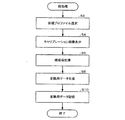
図5は、本実施形態の一例に係る前処理のフローチャートである。
【0067】
まず、色域演算部160は、ユーザーの指定や画像の種別によって目標プロファイルを選択する(ステップS2)。
【0068】
目標プロファイルが選択された後、プロジェクタ20は、キャリブレーション信号発生部150からキャリブレーション信号値(R2、G2、B2)を発生させる。
【0069】
キャリブレーション信号発生部150は、当該キャリブレーション信号値をプロジェクタ色変換部121に出力する。
【0070】
プロジェクタ色変換部121は、デフォルト(初期状態)の変換用データを用いて、キャリブレーション信号を変換してRGB信号値(R3、G3、B3)として出力する。
【0071】
そして、ガンマ処理部170は、各RGB信号値(R3、G3、B3)に対してガンマ処理を行ってRGB信号値(R4、G4、B4)として出力する。
【0072】
そして、D/A変換部180は、当該デジタル形式のRGB信号値(R4、G4、B4)をアナログ形式のRGB信号(R5、G5、B5)に変換する。そして、L/V駆動部190は、アナログRGB信号(R5、G5、B5)に基づき、液晶ライトバルブを駆動する。そして、プロジェクタ20は、キャリブレーション画像を画像表示領域12に投写表示する(ステップS4)。
【0073】
画像表示領域12にキャリブレーション画像が表示された状態で、色光センサー60は、視環境を示す環境情報の一種として三刺激値の検出を行う(ステップS6)。なお、検出する三刺激値は、絶対値、相対値のいずれでもよい。
【0074】
このように、キャリブレーション画像を用いて、視環境の把握を行うことにより、より適切に視環境を把握することができる。したがって、画像の色の見えをより適切に再現することができる。
【0075】
そして、変換用データ生成部130は、色光センサー60からの三刺激値、選択された目標プロファイルおよびプロジェクタプロファイルに基づき、変換用データを生成し(ステップS8)、当該変換用データを変換用データ記憶部123に記憶する(ステップS10)。
【0076】
このようにして、前処理の段階において、視環境が把握され、把握された視環境に応じて変換用データが生成され、変換用データ記憶部123に記憶される。
【0077】
このように、画像のキャリブレーション時に変換用データを生成することにより、キャリブレーションの指示に応じた正確な変換用データを生成することができる。
【0078】
また、このように、キャリブレーション時に変換用データを生成することにより、プレゼンテーション実行時の環境や目標色に柔軟に対応することができる。
【0079】
次に、本処理について説明する。
【0080】
図6は、本実施形態の一例に係る本処理のフローチャートである。
【0081】
A/D変換部110は、動画像であるアナログRGB信号(R1、G1、B1)をR、G、Bの各画像信号値(R2、G2、B2)に変換する。
【0082】
プロジェクタ色変換部121は、デジタル画像データであるR、G、Bの各画像信号値(R2、G2、B2)を入力する(ステップS12)。
【0083】
変換部125は、入力されたR、G、Bの各画像信号値(R2、G2、B2)に基づき、変換用データ記憶部125に記憶された変換用データから対応するR、G、Bの各画像信号値を抽出する(ステップS14)。例えば、変換部125は、上述した白を再現する場合、R信号値については、(R、G、B)=(250、0、8)を抽出し、G信号値については、(R、G、B)=(5、189、15)を抽出し、B信号値については、(R、G、B)=(0、12、196)を抽出する。そして、変換部125は、抽出したR信号値、G信号値およびB信号値を統合部127に出力する。
【0084】
このようにして画像信号値の種別ごとに色変換が行われる。
【0085】
そして、統合部127は、変換部125によって変換(抽出)されたR、G、Bの各画像信号値を統合する(ステップS16)。例えば、白の場合、統合後のR、G、Bの各画像信号値は、(R、G、B)=(255、201、219)となる。すなわち、R3信号値=255、G3信号値=201、B3信号値=219となる。
【0086】
そして、プロジェクタ20は、色変換されたR、G、Bの各画像信号値(R3、G3、B3)を、ガンマ処理部170を用いてガンマ処理してR、G、Bの各画像信号値(R4、G4、B4)として出力する(ステップS18)。
【0087】
そして、ガンマ処理後のデジタルRGB信号値(R4、G4、B4)を、D/A変換部180を用いてD/A変換し、変換されたアナログRGB信号(R5、G5、B5)を用いて実際のプレゼンテーション画像を表示する(ステップS20)。
【0088】
なお、動画像を表示する場合、実際には、1画像を構成する各画素ごとにステップS12〜S18の処理が行われ、1画像(1フレーム)が60分の1秒ごとに切り替わるため、1画像分の処理を60分の1秒ごとに行う。
【0089】
以上のように、本実施の形態によれば、色変換用データとして、3D−LUTではなく、図4に示すような信号別に対応付けられた変換用データを用いて色変換を行うことにより、色変換用データによる記憶領域の占有量を低減できる。
【0090】
また、色の変換時に線形補間等の複雑な演算が不要であり、データ抽出と和算だけで色の変換を行うことにより、高速に色変換を行うことができる。
【0091】
これにより、動画データを処理する場合でも、リアルタイムに処理することができ、快適に目標色に適合した動画を表示することができる。
【0092】
また、本実施の形態では、色光センサー60を用いて視環境を把握することにより、視環境を考慮して画像を投写表示している。
【0093】
これにより、画像表示時の視環境に適応して画像を表示することができ、表示環境の差を吸収して適用される環境によらずに同一の画像を表示することができる。したがって、複数の異なる場所において、ほぼ同一の色を短時間で再現することができる。
【0094】
(ハードウェアの説明)
なお、上述した各部に用いるハードウェアとしては、例えば、以下のものを適用できる。
【0095】
例えば、A/D変換部110としては、例えばA/Dコンバーター等、D/A変換部180としては、例えばD/Aコンバーター等、L/V駆動部190としては、例えば液晶ライトバルブ駆動ドライバ等、変換用データ生成部としては例えばCPU等、例えばCPUやRAM等、ガンマ処理部170としては、例えば画像処理回路やASIC等、プロジェクタ色変換部121および色域演算部160としては、例えばCPUやRAM等を用いて実現できる。なお、これら各部は回路のようにハードウェア的に実現してもよいし、ドライバのようにソフトウェア的に実現してもよい。
【0096】
また、図3に示すように、これら各部の機能を情報記憶媒体300からプログラムを読み取って実現してもよい。情報記憶媒体300としては、例えば、CD−ROM、DVD−ROM、ROM、RAM、HDD等を適用でき、その情報の読み取り方式は接触方式であっても、非接触方式であってもよい。
【0097】
また、情報記憶媒体300に代えて、上述した各機能を実現するためのプログラムを、伝送路を介してホスト装置等からダウンロードすることによって上述した各機能を実現することも可能である。すなわち、上述した各機能を実現するための情報は、搬送波に具現化されるものであってもよい。
【0098】
さらに、色光センサー60については以下のハードウェアを適用できる。
【0099】
例えば、各刺激値を選択的に透過するカラーフィルターおよびフォトダイオード、フォトダイオードからのアナログ信号をデジタル信号に変換するA/Dコンバーターおよび当該デジタル信号を増幅するOPアンプ等を適用できる。
【0100】
以上、本発明を適用した好適な実施の形態について説明してきたが、本発明の適用は上述した実施例に限定されない。
【0101】
(変形例)
例えば、図4に示す変換用データは、数値をそのまま用いたものであるが、各画像信号値間の比率で表した変換用データを用いてもよい。
【0102】
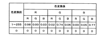
図7は、本実施形態の他の一例に係る変換用データを示す模式図である。
【0103】
例えば、図4に示す変換用データを各画像信号値間の比率で示せば図7のようになる。R信号値、G信号値、B信号値のそれぞれの値が全て0の場合は、変換後の画像信号値の全ての値も0であるため、実質的に変換用データ記憶部123に記憶する必要があるのは9つのデータである。
【0104】
すなわち、R信号値、G信号値、B信号値のそれぞれの値がすべて1〜255である場合、色変換後のR信号値は、(R:G:B)=(0.98:0.00:0.03)で表され、色変換後のG信号値は、(R:G:B)=(0.02:0.74:0.06)で表され、色変換後のB信号値は、(R:G:B)=(0.00:0.05:0.77)で表される。
【0105】
したがって、これらの9つの比率を示す数値だけを変換用データ記憶部123に記憶すればよい。
【0106】
また、図7に示す比率を用いる方式によれば、図4に示す例では、9×256=2304個のデータが必要となるため、比率の演算が必要となる点で、数値で表す場合と比べて若干演算量は増えるが、図4に示す場合よりもデータ量をより低減できる。
【0107】
また、上述したプロジェクタのような投写型画像表示装置以外の表示手段で画像表示を行ってプレゼンテーション等を行う場合にも本発明を適用できる。このような表示手段としては、例えば、液晶プロジェクタのほか、DMD(Digital Micromirror Device)を用いたプロジェクタや、CRT(Cathode Ray Tube)、PDP(Plasma Display Panel)、FED(Field Emission Display)、EL(Electro Luminescence)、直視型液晶表示装置等のディスプレイ装置等が該当する。なお、DMDは、米国テキサスインスツルメンツ社の商標である。また、プロジェクタは前面投写型のものに限られず、背面投写型のものであってもよい。
【0108】
また、プレゼンテーション以外にも、ミーティング、医療、デザイン・ファッション分野、営業活動、コマーシャル、教育、さらには映画、TV、ビデオ、ゲーム等の一般映像等における画像表示を行う場合にも本発明は有効である。もちろん、動画像データだけでなく、静止画像データを処理する場合にも本発明は有効である。
【0109】
さらに、sRGBを目標色として画像表示する場合だけでなく、スキャナで取り込んだ画像の色や、PCで生成した画像の色を目標色として、画像をモニターで表示したり、プリンタで印刷したりする場合等にも本発明は有効である。このような場合にも、色変換に必要となるデータ量を低減できる。
【0110】
また、上述した実施例では、RGB信号値を用いたが、CMY値やCMYK値を用いる場合にも本発明を適用できる。
【0111】
また、視環境把握手段としては、色光センサー60以外にも、例えば、CCDカメラ、CMOSカメラ等の撮像手段を適用することも可能である。
【0112】
なお、上述したスクリーン10は、反射型のものであったが、透過型のものであってもよい。
【0113】
なお、上述したプロジェクタ20のプロジェクタ画像処理部100の機能は、単体の画像表示装置(例えば、プロジェクタ20)で実現してもよいし、複数の処理装置で分散して(例えば、プロジェクタ20とPCとで分散処理)実現してもよい。
【図面の簡単な説明】
【図1】本実施形態の一例に係る画像処理システムの概略説明図である。
【図2】 従来のプロジェクタ内のプロジェクタ画像処理部の機能ブロックの一例を示す図である。
【図3】 本実施形態の一例に係るプロジェクタ内のプロジェクタ画像処理部の機能ブロック図である。
【図4】本実施形態の一例に係る変換用データを示す模式図である。
【図5】本実施形態の一例に係る前処理のフローチャートである。
【図6】本実施形態の一例に係る本処理のフローチャートである。
【図7】本実施形態の他の一例に係る変換用データを示す模式図である。
【符号の説明】
20 プロジェクタ
50 レーザーポインタ
60 色光センサー
80 環境光
120、121 プロジェクタ色変換部
123 変換用データ記憶部
125 変換部
127 統合部
130 変換用データ生成部
150 キャリブレーション信号発生部
160 色域演算部
162 目標プロファイル記憶部
164 プロジェクタプロファイル記憶部
170 ガンマ処理部
300 情報記憶媒体[0001]
BACKGROUND OF THE INVENTION
The present invention relates to an image processing system, a program, and an information storage medium that convert image data to reproduce a target color.
[0002]
[Background Art and Problems to be Solved by the Invention]
In general, when color conversion of image data is performed to reproduce a target color (for example, a color that conforms to a standard such as sRGB), a three-dimensional lookup table (hereinafter referred to as “3D-LUT”) and an interpolation operation are performed. Color conversion is performed in combination.
[0003]
Although a method of expressing a combination of all image signals (for example, R signal, G signal, B signal, etc.) with a 3D-LUT is also conceivable, in a three-color 8-bit system, it becomes about 50 MB (megabytes), and a large amount of memory is stored. Capacity is required (refer to
[0004]
In addition, when performing the interpolation calculation, the interpolation calculation is performed using 8 points, but this method takes a lot of calculation time.
[0005]
In order to shorten the calculation time, a method of dividing a cube including a target point in a 3D-LUT space and using a triangular pyramid including the target point, that is, using four points has also been proposed (see the same book). ).
[0006]
However, the extraction of these four points and the interpolation calculation itself are complicated and take a long time.
[0007]
In particular, when an image is rewritten in real time in 1/60 second like a moving image, it is important to shorten the calculation time required for color conversion.
[0008]
The present invention has been made in view of the above problems, and its purpose is to perform color conversion with less storage capacity and less computation time when image data is converted to reproduce a target color. It is an object of the present invention to provide an image processing system, a program, and an information storage medium capable of performing the above.
[0009]
[Means for Solving the Problems]
In order to solve the above problems, an image processing system according to the present invention is an image processing system that converts image data represented by a plurality of types of image signal values in order to reproduce a target color.
Including color conversion means for converting the image data based on predetermined color conversion data;
The color conversion data includes signal-specific association data for associating image signal values after color conversion with a plurality of types of image signal values before color conversion for each type of image signal value,
The color conversion means includes
Means for performing color conversion of the image signal value for each type of the image signal value based on the input image signal value and the signal-specific association data;
Means for integrating image signal values subjected to color conversion for each type of the image signal values;
It is characterized by including.
[0010]
A program according to the present invention is a program for converting image data expressed by a plurality of types of image signal values in order to reproduce a target color, and is a computer- readable program,
Based on predetermined color conversion data, the computer functions as color conversion means for converting the image data,
The color conversion data includes signal-specific association data for associating image signal values after color conversion with a plurality of types of image signal values before color conversion for each type of image signal value,
The color conversion means includes
Means for performing color conversion of the image signal value for each type of the image signal value based on the input image signal value and the signal-specific association data;
Means for integrating image signal values subjected to color conversion for each type of the image signal values;
It is characterized by including.
[0011]
An information storage medium according to the present invention is a computer- readable information storage medium, and stores a program for causing the computer to realize the above means.
[0012]
According to the present invention, for each type of image signal value, obtain image signal values represented by the plurality of types of image signal values, and integrate the obtained image signal values for each type of image signal value, A target image signal value can be obtained.
[0013]
Thereby, the storage capacity required for the color conversion data can be reduced, and the calculation time for color conversion can be shortened.
[0014]
That is, for example, as described above, in the case of a 3D-LUT composed of 8 bits of 3 colors, about 50 MB is required. On the other hand, according to the present invention, 24 bits × 256 × 3 colors = 2304B (bytes) is sufficient.
[0015]
In addition, since the calculation algorithm at the time of color conversion only needs to be integrated, that is, search for association data for each signal and summation, the calculation time can be reduced as compared with the conventional method using linear interpolation or the like.
[0016]
The image processing system may include color conversion data generation means for generating the color conversion data according to the target color in a predetermined situation.
[0017]
The program may cause a computer to function as color conversion data generation means for generating the color conversion data according to the target color in a predetermined situation.
[0018]
The information storage medium may store a program that causes a computer to function as the color conversion data generation means.
[0019]
According to this, since color conversion data can be generated flexibly, color conversion corresponding to various target colors can be performed.
[0020]
In the image processing system, the program, and the information storage medium, the association data for each signal may represent the plurality of types of image signal values as a ratio.
[0021]
According to this, the required storage capacity can be further reduced by expressing the ratio. That is, since the colors to be reproduced are the same, the ratio between the image signal values is constant regardless of the gradation. For example, in the case of three colors (three kinds of signal values), nine data are sufficient.
[0022]
In the image processing system, the program, and the information storage medium, the image data may be moving image data.
[0023]
According to this, since color conversion can be performed in real time, color conversion of moving image data can be comfortably performed.
[0024]
In the image processing system, the program, and the information storage medium, the color conversion data generation unit may generate the color conversion data based on environment information indicating a visual environment.
[0025]
According to this, even when the target color is changed depending on the visual environment, color conversion according to the visual environment can be performed.
[0026]
In the image processing system, the program, and the information storage medium, the color conversion data generation unit may generate the color conversion data when the image is calibrated.
[0027]
According to this, by generating color conversion data at the time of image calibration, it is possible to generate accurate color conversion data according to the calibration instruction.
[0028]
DETAILED DESCRIPTION OF THE INVENTION
Hereinafter, a case where the present invention is applied to an image processing system using a liquid crystal projector that projects and displays moving images will be described as an example with reference to the drawings.
[0029]
(Description of the entire system)
FIG. 1 is a schematic explanatory diagram of an image processing system according to an example of the present embodiment.
[0030]
A predetermined moving image or still image for projection is projected from a
[0031]
When such a presentation is performed, the appearance of the image in the
[0032]
In recent years, the
[0033]
In a conventional projector, only color conversion is performed based on an input / output profile indicating input / output characteristics unique to the projector, and a viewing environment in which an image is projected and displayed is not taken into consideration. A profile means characteristic data.
[0034]
However, as described above, it is difficult to unify the appearance of the colors of an image without considering the visual environment. The color appearance is determined by three factors: light, reflection or transmission of light of the object, and vision.
[0035]
In this embodiment, an image processing system capable of reproducing appropriate image colors is realized by grasping the visual environment reflecting the reflection or transmission of light and target light.
[0036]
By the way, when such an image is displayed, a color conforming to a standard such as sRGB is set as a target color, and the color of the image is converted in order to appropriately reproduce the target color in a visual environment to which the image processing system is applied. Do.
[0037]
However, according to the conventional method, a large storage capacity for the 3D-LUT is required for the conversion of the color of the image, and a long calculation time is required for the interpolation calculation.
[0038]
FIG. 2 is a diagram illustrating an example of functional blocks of a projector
[0039]
In the projector, an R1 signal, a G1 signal, and a B1 signal constituting an analog RGB signal sent from a PC or the like are input to the A /
[0040]
The R3 signal value, the G3 signal value, and the B3 signal value that have undergone color conversion are subjected to gamma processing, and the image signal values that have been converted into the R4 signal value, the G4 signal value, and the B4 signal value are input to the D /
[0041]
The projector
[0042]
The
[0043]
As described above, since the calibration image signal value is generated inside the
[0044]
The projector
[0045]
In addition, the projector
[0046]
More specifically, the 3D-
[0047]
Next, the color
[0048]
In addition, the color
[0049]
Here, the target profile is a kind of input / output characteristic data of a color to be targeted (here, a color in the sRGB standard). The projector profile is a kind of input / output characteristic data corresponding to the projector model.
[0050]
Further, the
[0051]
As described above, since the color conversion is conventionally performed using the 3D-LUT, the capacity of the 3D-LUT stored in the 3D-
[0052]
In particular, when a moving image is displayed as in the present embodiment, real-time moving image display cannot be performed if color conversion takes time.
[0053]
In this embodiment, as color conversion data that replaces the 3D-LUT, for each type of image signal value, the image signal value after color conversion is associated with a plurality of types of image signal values before color conversion. Use association data. Then, color conversion is performed using the signal-specific association data, and the image signal values subjected to the color conversion are integrated for each type of image signal value.
[0054]
Thereby, the storage capacity required for the color conversion data can be reduced, and the calculation time for color conversion can be shortened.
[0055]
Next, functional blocks of the projector
[0056]
FIG. 3 is a functional block diagram of the projector
[0057]
A difference from the projector
[0058]
The conversion
[0059]
FIG. 4 is a schematic diagram illustrating conversion data according to an example of the present embodiment.
[0060]
In this embodiment, since RGB signal values are used, signal-specific association data is provided for each of the R signal value, the G signal value, and the B signal value. Here, the association data for each signal is represented by an R signal value, a G signal value, and a B signal value before color conversion.
[0061]
Specifically, for example, when the R signal value, the G signal value, and the B signal value are 255, 255, and 255, that is, when the value is white, the R signal value after color conversion is (R , G, B) = (250, 0, 8), and the G signal value after color conversion is represented by (R, G, B) = (5, 189, 15), and B after color conversion. The signal value is represented by (R, G, B) = (0, 12, 196).
[0062]
As described above, what is originally represented by only one image signal value needs to be represented by three image signal values because the color gamut for reproducing the target color depending on the visual environment is a standard color. This is because, unlike the gamut, a color gamut shift occurs. For example, in a standard environment, the red RGB signal value is (R, G, B) = (255, 0, 0). It is necessary to express using all signal values of R, G, and B.
[0063]
Further, the
[0064]
Note that the specific numerical values shown in FIG. 4 are merely examples, and vary depending on the device such as the
[0065]
Next, the flow of processing using each unit shown in FIG. 3 will be described. In the present embodiment, calibration, grasping of the visual environment, generation of conversion data, and the like are performed in pre-processing before presentation, and color conversion and the like are performed in the main processing at the time of presentation.
[0066]
FIG. 5 is a flowchart of preprocessing according to an example of the present embodiment.
[0067]
First, the color
[0068]
After the target profile is selected, the
[0069]
The calibration
[0070]
The projector
[0071]
Then, the
[0072]
Then, the D /
[0073]
In a state where the calibration image is displayed in the
[0074]
As described above, the visual environment can be grasped more appropriately by grasping the visual environment using the calibration image. Therefore, the color appearance of the image can be reproduced more appropriately.
[0075]
Then, the conversion
[0076]
In this way, in the preprocessing stage, the visual environment is grasped, conversion data is generated according to the grasped visual environment, and is stored in the conversion
[0077]
Thus, by generating the conversion data at the time of image calibration, it is possible to generate accurate conversion data in accordance with the calibration instruction.
[0078]
Further, by generating the conversion data at the time of calibration in this way, it is possible to flexibly cope with the environment and target color at the time of presentation execution.
[0079]
Next, this process will be described.
[0080]
FIG. 6 is a flowchart of this processing according to an example of this embodiment.
[0081]
The A /
[0082]
The projector
[0083]
Based on the input R, G, and B image signal values (R2, G2, and B2), the
[0084]
In this way, color conversion is performed for each type of image signal value.
[0085]
Then, the
[0086]
The
[0087]
Then, the digital RGB signal values (R4, G4, B4) after the gamma processing are D / A converted using the D /
[0088]
Note that when displaying a moving image, the processing of steps S12 to S18 is actually performed for each pixel constituting one image, and one image (one frame) is switched every 1/60 second. Image processing is performed every 1 / 60th of a second.
[0089]
As described above, according to the present embodiment, by performing color conversion using the conversion data associated with each signal as shown in FIG. 4 instead of the 3D-LUT as the color conversion data, The amount of storage area occupied by the color conversion data can be reduced.
[0090]
In addition, complicated operations such as linear interpolation are not required at the time of color conversion, and color conversion can be performed at high speed by performing color conversion only by data extraction and summation.
[0091]
Thereby, even when moving image data is processed, it can be processed in real time, and a moving image suitable for the target color can be displayed comfortably.
[0092]
Further, in the present embodiment, by grasping the viewing environment using the
[0093]
As a result, it is possible to display an image in accordance with the viewing environment at the time of image display, and it is possible to display the same image regardless of the environment applied by absorbing the difference in display environment. Therefore, substantially the same color can be reproduced in a short time at a plurality of different locations.
[0094]
(Hardware description)
In addition, as hardware used for each part mentioned above, the following can be applied, for example.
[0095]
For example, the A /
[0096]
Further, as shown in FIG. 3, the functions of these units may be realized by reading a program from the
[0097]
Further, instead of the
[0098]
Further, the following hardware can be applied to the
[0099]
For example, a color filter and a photodiode that selectively transmit each stimulus value, an A / D converter that converts an analog signal from the photodiode into a digital signal, an OP amplifier that amplifies the digital signal, and the like can be applied.
[0100]
The preferred embodiments to which the present invention is applied have been described above, but the application of the present invention is not limited to the above-described examples.
[0101]
(Modification)
For example, the conversion data shown in FIG. 4 uses numerical values as they are, but conversion data represented by a ratio between image signal values may be used.
[0102]
FIG. 7 is a schematic diagram illustrating conversion data according to another example of the present embodiment.
[0103]
For example, if the conversion data shown in FIG. 4 is represented by the ratio between the image signal values, the result is as shown in FIG. When each of the R signal value, the G signal value, and the B signal value is all 0, all the converted image signal values are also 0, and thus are substantially stored in the conversion
[0104]
That is, when the R signal value, the G signal value, and the B signal value are all 1 to 255, the R signal value after color conversion is (R: G: B) = (0.98: 0. 00: 0.03), and the G signal value after color conversion is represented by (R: G: B) = (0.02: 0.74: 0.06), and the B signal after color conversion. The value is represented by (R: G: B) = (0.00: 0.05: 0.77).
[0105]
Therefore, only the numerical values indicating these nine ratios need be stored in the conversion
[0106]
Further, according to the method using the ratio shown in FIG. 7, the example shown in FIG. 4 requires 9 × 256 = 2304 pieces of data, so that the calculation of the ratio is necessary. Compared to the case shown in FIG. 4, the amount of data can be further reduced, although the amount of calculation slightly increases.
[0107]
The present invention can also be applied to a case where an image is displayed by a display unit other than the projection type image display device such as the projector described above to give a presentation. Examples of such display means include a liquid crystal projector, a projector using a DMD (Digital Micromirror Device), a CRT (Cathode Ray Tube), a PDP (Plasma Display Panel), and an FED (Field Emission Display). Electro Luminescence), display devices such as direct-view liquid crystal display devices, and the like are applicable. DMD is a trademark of Texas Instruments Incorporated. Further, the projector is not limited to the front projection type, and may be a rear projection type.
[0108]
In addition to presentations, the present invention is also effective when displaying images in meetings, medical care, design / fashion fields, sales activities, commercials, education, and general images such as movies, TV, videos, and games. is there. Of course, the present invention is effective when processing not only moving image data but also still image data.
[0109]
In addition to displaying an image with sRGB as a target color, the image is displayed on a monitor or printed with a printer using the color of an image captured by a scanner or the color of an image generated by a PC as a target color. In some cases, the present invention is also effective. Even in such a case, the amount of data required for color conversion can be reduced.
[0110]
In the above-described embodiments, RGB signal values are used. However, the present invention can also be applied to the case where CMY values or CMYK values are used.
[0111]
In addition to the
[0112]
The
[0113]
Note that the function of the projector
[Brief description of the drawings]
FIG. 1 is a schematic explanatory diagram of an image processing system according to an example of the present embodiment.
FIG. 2 is a diagram illustrating an example of functional blocks of a projector image processing unit in a conventional projector.
FIG. 3 is a functional block diagram of a projector image processing unit in the projector according to an example of the present embodiment.
FIG. 4 is a schematic diagram showing conversion data according to an example of the present embodiment.
FIG. 5 is a flowchart of pre-processing according to an example of the present embodiment.
FIG. 6 is a flowchart of this processing according to an example of the present embodiment.
FIG. 7 is a schematic diagram showing conversion data according to another example of the present embodiment.
[Explanation of symbols]
20
Claims (13)
所定の色変換用データに基づき、前記画像データを変換する色変換手段を含み、
前記色変換用データは、前記画像信号値の種別ごとに、色変換前の1種類の画像信号値と、色変換後の前記複数種の画像信号値とを対応付けるための信号別対応付けデータを含み、
前記色変換手段は、
入力される画像信号値を、前記画像信号値の種別ごとに、前記信号別対応付けデータに基づき、前記1種類の画像信号値を前記複数種の画像信号値に変換する手段と、
変換された前記複数種の画像信号値を、前記画像信号値の種別ごとに統合する手段と、
を含むことを特徴とする画像処理システム。In an image processing system that converts image data represented by a plurality of types of image signal values in order to reproduce a target color,
Including color conversion means for converting the image data based on predetermined color conversion data;
The color conversion data for each type of the image signal values, and one of the image signal values before color conversion, the signal-specific correlation data for associating said plurality of types of image signal values after color conversion Including
The color conversion means includes
An image signal value inputted, and means for converting for each type of the image signal values, based on the signal by correlation data, the one type of image signal values in the image signal values of the plurality of types,
The converted plurality of kinds of image signal values, and means for integrating for each type of the image signal values,
An image processing system comprising:
前記目標色に応じて前記色変換用データを生成する色変換用データ生成手段を含むことを特徴とする画像処理システム。In claim 1,
An image processing system which comprises a color conversion data generation means for generating the color conversion data in accordance with the prior SL target color.
前記信号別対応付けデータは、前記色変換後の前記複数種の画像信号値を前記色変換前の1種類の画像信号値に対する比率で表現したものであることを特徴とする画像処理システム。In any one of Claims 1, 2.
An image processing system, wherein the signal-specific correlation data is a plurality of types of image signal values after the color conversion as expressed in percentage of one type of image signal values before the color conversion.
前記画像データは、動画像データであることを特徴とする画像処理システム。In any one of Claims 1-3,
The image processing system, wherein the image data is moving image data.
前記色変換用データ生成手段は、視環境を示す環境情報に基づき、前記色変換用データを生成することを特徴とする画像処理システム。In any one of Claims 2-4,
The color conversion data generating means generates the color conversion data based on environment information indicating a visual environment.
前記色変換用データ生成手段は、画像の校正時に、前記色変換用データを生成することを特徴とする画像処理システム。In any one of Claims 2-5,
The color conversion data generating means generates the color conversion data at the time of image calibration.
所定の色変換用データに基づき、前記画像データを変換する色変換手段としてコンピュータを機能させ、
前記色変換用データは、前記画像信号値の種別ごとに、色変換前の1種類の画像信号値と、色変換後の前記複数種の画像信号値とを対応付けるための信号別対応付けデータを含み、
前記色変換手段は、
入力される画像信号値を、前記画像信号値の種別ごとに、前記信号別対応付けデータに基づき、前記1種類の画像信号値を前記複数種の画像信号値に変換する手段と、
変換された前記複数種の画像信号値を、前記画像信号値の種別ごとに統合する手段と、
、
を含むことを特徴とするプログラム。A program for converting image data represented by a plurality of types of image signal values in order to reproduce a target color, a computer-readable program,
Based on predetermined color conversion data, the computer functions as color conversion means for converting the image data,
The color conversion data for each type of the image signal values, and one of the image signal values before color conversion, the signal-specific correlation data for associating said plurality of types of image signal values after color conversion Including
The color conversion means includes
An image signal value inputted, and means for converting for each type of the image signal values, based on the signal by correlation data, the one type of image signal values in the image signal values of the plurality of types,
The converted plurality of kinds of image signal values, and means for integrating for each type of the image signal values,
,
The program characterized by including.
前記目標色に応じて前記色変換用データを生成する色変換用データ生成手段としてコンピュータを機能させることを特徴とするプログラム。In claim 7,
Program for causing a computer to function as the color conversion data generation means for generating the color conversion data in accordance with the prior SL target color.
前記信号別対応付けデータは、前記色変換後の前記複数種の画像信号値を前記色変換前の1種類の画像信号値に対する比率で表現したものであることを特徴とするプログラム。In any one of Claims 7 and 8,
Said signal by mapping data, the program characterized in that said plurality of kinds of image signal values after the color conversion is a representation as a ratio to one type of image signal values before the color conversion.
前記画像データは、動画像データであることを特徴とするプログラム。In any one of Claims 7-9,
The program characterized in that the image data is moving image data.
前記色変換用データ生成手段は、視環境を示す環境情報に基づき、前記色変換用データを生成することを特徴とするプログラム。In any one of Claims 8-10,
The color conversion data generation means generates the color conversion data based on environment information indicating a visual environment.
前記色変換用データ生成手段は、画像の校正時に、前記色変換用データを生成することを特徴とするプログラム。In any one of Claims 8-11,
The color conversion data generation means generates the color conversion data at the time of image calibration.
請求項8〜12のいずれかのプログラムを記憶したことを特徴とする情報記憶媒体。An information storage medium readable by a computer,
An information storage medium storing the program according to claim 8.
Priority Applications (5)
| Application Number | Priority Date | Filing Date | Title |
|---|---|---|---|
| JP2001086778A JP3729252B2 (en) | 2001-03-26 | 2001-03-26 | Image processing system, program, and information storage medium |
| PCT/JP2002/002835 WO2002078356A1 (en) | 2001-03-26 | 2002-03-25 | Image processing system, information storage medium, and image processing method |
| EP02705473A EP1377076A4 (en) | 2001-03-26 | 2002-03-25 | Image processing system, information storage medium, and image processing method |
| US10/296,502 US6899431B2 (en) | 2001-03-26 | 2002-03-25 | Image processing system, projector, information storage medium, and image processing method |
| CN02801782.XA CN1191723C (en) | 2001-03-26 | 2002-03-25 | Image processing system, information storage medium, and image processing method |
Applications Claiming Priority (1)
| Application Number | Priority Date | Filing Date | Title |
|---|---|---|---|
| JP2001086778A JP3729252B2 (en) | 2001-03-26 | 2001-03-26 | Image processing system, program, and information storage medium |
Publications (3)
| Publication Number | Publication Date |
|---|---|
| JP2002290986A JP2002290986A (en) | 2002-10-04 |
| JP2002290986A5 JP2002290986A5 (en) | 2004-10-14 |
| JP3729252B2 true JP3729252B2 (en) | 2005-12-21 |
Family
ID=18942108
Family Applications (1)
| Application Number | Title | Priority Date | Filing Date |
|---|---|---|---|
| JP2001086778A Expired - Fee Related JP3729252B2 (en) | 2001-03-26 | 2001-03-26 | Image processing system, program, and information storage medium |
Country Status (5)
| Country | Link |
|---|---|
| US (1) | US6899431B2 (en) |
| EP (1) | EP1377076A4 (en) |
| JP (1) | JP3729252B2 (en) |
| CN (1) | CN1191723C (en) |
| WO (1) | WO2002078356A1 (en) |
Families Citing this family (16)
| Publication number | Priority date | Publication date | Assignee | Title |
|---|---|---|---|---|
| US7154458B2 (en) | 2002-08-21 | 2006-12-26 | Nec Viewtechnology, Ltd. | Video display device with spatial light modulator |
| KR100612835B1 (en) | 2002-12-12 | 2006-08-18 | 삼성전자주식회사 | A method and apparatus for generating user preference data regarding color characteristic of image, and method and apparatus for converting color preference of image using the method and appatatus |
| JP4040046B2 (en) * | 2003-03-14 | 2008-01-30 | 富士通株式会社 | Pointer area detection apparatus, method and program, image association apparatus, method and program, content distribution server, and content distribution method |
| TWI249959B (en) * | 2003-05-16 | 2006-02-21 | Seiko Epson Corp | Image processing system, projector, information memorizing medium and image processing method |
| JP2005210208A (en) * | 2004-01-20 | 2005-08-04 | Fuji Xerox Co Ltd | Image processor, image processing method, and program |
| KR100565810B1 (en) * | 2004-06-16 | 2006-03-29 | 삼성전자주식회사 | Color signal processing apparatus and method of using the same |
| KR101133572B1 (en) * | 2005-06-21 | 2012-04-05 | 삼성전자주식회사 | Color gamut reproducing apparatus having wide color gamut and color signal processing method the same |
| KR100849309B1 (en) * | 2005-12-29 | 2008-07-29 | 삼성전자주식회사 | Method and apparatus for adjusting projecting screen in projector |
| KR20080029410A (en) * | 2006-09-29 | 2008-04-03 | 삼성전자주식회사 | Display system and image processing method thereof |
| JP2010521098A (en) * | 2007-03-08 | 2010-06-17 | ヒューレット−パッカード デベロップメント カンパニー エル.ピー. | True color communication |
| EP2200268B1 (en) * | 2008-12-22 | 2012-02-08 | Thomson Licensing | Method of calibration of a target color reproduction device |
| JP2010244484A (en) * | 2009-04-10 | 2010-10-28 | Funai Electric Co Ltd | Image display device, image display method and image display program |
| JP5430254B2 (en) * | 2009-07-01 | 2014-02-26 | キヤノン株式会社 | Image display apparatus and control method thereof |
| US8434873B2 (en) * | 2010-03-31 | 2013-05-07 | Hong Kong Applied Science and Technology Research Institute Company Limited | Interactive projection device |
| JP6210772B2 (en) * | 2013-07-22 | 2017-10-11 | キヤノン株式会社 | Information processing apparatus, imaging apparatus, control method, and program |
| JP6554887B2 (en) * | 2015-04-14 | 2019-08-07 | 富士ゼロックス株式会社 | Image generating apparatus, evaluation system, and program |
Family Cites Families (25)
| Publication number | Priority date | Publication date | Assignee | Title |
|---|---|---|---|---|
| CH673534A5 (en) | 1987-10-19 | 1990-03-15 | Tecan Ag | |
| US5218647A (en) * | 1990-12-12 | 1993-06-08 | Ricoh Corporation | Method to convert between 2 color space on a 32 bit μ-processor |
| JP2876853B2 (en) | 1991-10-24 | 1999-03-31 | 松下電器産業株式会社 | Color converter |
| JPH06217338A (en) | 1993-01-20 | 1994-08-05 | Fujitsu General Ltd | Automatic hue adjustment device |
| JPH0980849A (en) | 1995-09-12 | 1997-03-28 | Canon Inc | Image processor and image output device |
| JP3412996B2 (en) | 1995-12-28 | 2003-06-03 | キヤノン株式会社 | Image processing apparatus and method |
| KR100363250B1 (en) | 1995-12-30 | 2003-03-15 | 삼성전자 주식회사 | Method and system for processing colors using two-dimensional chrominance division |
| JPH09271036A (en) * | 1996-03-29 | 1997-10-14 | Nec Corp | Method and device for color image display |
| JP3603528B2 (en) * | 1996-04-13 | 2004-12-22 | ソニー株式会社 | Hue adjustment method and hue adjustment device |
| JPH10308950A (en) | 1997-05-08 | 1998-11-17 | Digital Vision Lab:Kk | Color correction device |
| JPH11215386A (en) | 1998-01-28 | 1999-08-06 | Fuji Xerox Co Ltd | Device and method for image display |
| US6201530B1 (en) * | 1998-05-29 | 2001-03-13 | Flashpoint Technology, Inc. | Method and system of optimizing a digital imaging processing chain |
| JP4212165B2 (en) | 1998-11-13 | 2009-01-21 | オリンパス株式会社 | Color reproduction system |
| JP2000311243A (en) | 1999-04-28 | 2000-11-07 | Sony Corp | Image color correction method and device |
| JP4262359B2 (en) | 1999-06-18 | 2009-05-13 | オリンパス株式会社 | Color reproduction system |
| JP2001008044A (en) | 1999-06-21 | 2001-01-12 | Fuji Xerox Co Ltd | Image processor |
| JP2001060082A (en) * | 1999-08-24 | 2001-03-06 | Matsushita Electric Ind Co Ltd | Color reproducing terminal device and network color reproducing system |
| JP3707350B2 (en) * | 2000-05-08 | 2005-10-19 | セイコーエプソン株式会社 | Image display system, projector, image processing method, and information storage medium |
| JP3791586B2 (en) * | 2000-05-25 | 2006-06-28 | セイコーエプソン株式会社 | Image display system, image processing method, and information storage medium |
| JP3707371B2 (en) * | 2000-08-28 | 2005-10-19 | セイコーエプソン株式会社 | Image display system, image processing method, and information storage medium |
| JP3744778B2 (en) * | 2000-08-28 | 2006-02-15 | セイコーエプソン株式会社 | Image projection apparatus, image processing method, and information storage medium |
| CN1154082C (en) * | 2000-08-28 | 2004-06-16 | 精工爱普生株式会社 | Environment adaptive image display system. image processing method and information storing medium |
| JP3692989B2 (en) * | 2000-11-13 | 2005-09-07 | セイコーエプソン株式会社 | Image display system, projector, image processing method, program, and information storage medium |
| JP2002263304A (en) | 2001-03-08 | 2002-09-17 | Aruze Corp | Game machine, performance presentation expression method thereof, memory medium and server |
| JP3894302B2 (en) * | 2002-03-25 | 2007-03-22 | セイコーエプソン株式会社 | Image display system, image processing method, program, and information storage medium |
-
2001
- 2001-03-26 JP JP2001086778A patent/JP3729252B2/en not_active Expired - Fee Related
-
2002
- 2002-03-25 EP EP02705473A patent/EP1377076A4/en not_active Withdrawn
- 2002-03-25 CN CN02801782.XA patent/CN1191723C/en not_active Expired - Fee Related
- 2002-03-25 WO PCT/JP2002/002835 patent/WO2002078356A1/en active Application Filing
- 2002-03-25 US US10/296,502 patent/US6899431B2/en not_active Expired - Lifetime
Also Published As
| Publication number | Publication date |
|---|---|
| US6899431B2 (en) | 2005-05-31 |
| CN1191723C (en) | 2005-03-02 |
| US20040212783A1 (en) | 2004-10-28 |
| EP1377076A1 (en) | 2004-01-02 |
| WO2002078356A1 (en) | 2002-10-03 |
| EP1377076A4 (en) | 2005-03-02 |
| JP2002290986A (en) | 2002-10-04 |
| CN1463559A (en) | 2003-12-24 |
Similar Documents
| Publication | Publication Date | Title |
|---|---|---|
| JP3692989B2 (en) | Image display system, projector, image processing method, program, and information storage medium | |
| JP3719411B2 (en) | Image display system, projector, program, information storage medium, and image processing method | |
| JP4110408B2 (en) | Image display system, projector, image processing method, and information storage medium | |
| JP4605987B2 (en) | Projector, image processing method, and information storage medium | |
| JP3729252B2 (en) | Image processing system, program, and information storage medium | |
| JP3894302B2 (en) | Image display system, image processing method, program, and information storage medium | |
| EP2302919B1 (en) | Projector | |
| JP3514257B2 (en) | Image processing system, projector, image processing method, program, and information storage medium | |
| JP3705180B2 (en) | Image display system, program, information storage medium, and image processing method | |
| JP3719424B2 (en) | Image processing system, projector, image processing method, program, and information storage medium | |
| JP3290190B2 (en) | Image recording device | |
| WO2002076106A1 (en) | Environment-adaptive image display system, information storage medium, and image processing method | |
| JP3744778B2 (en) | Image projection apparatus, image processing method, and information storage medium | |
| JP3707371B2 (en) | Image display system, image processing method, and information storage medium | |
| JP4150876B2 (en) | Image display system, image processing method, program, and information storage medium | |
| KR100507779B1 (en) | Apparatus for compensating contrast of lightness according to brightness of surroundings | |
| JP2003187246A (en) | Image display system, program, information storage medium and image processing method | |
| JP4164659B2 (en) | Image display system and image display method | |
| JP2008011382A (en) | Gradation converting apparatus | |
| JP4860514B2 (en) | 7-axis color correction apparatus and method | |
| JP2001312259A (en) | Display device | |
| JPH04111679A (en) | Image forming device |
Legal Events
| Date | Code | Title | Description |
|---|---|---|---|
| A131 | Notification of reasons for refusal |
Free format text: JAPANESE INTERMEDIATE CODE: A131 Effective date: 20041228 |
|
| A521 | Request for written amendment filed |
Free format text: JAPANESE INTERMEDIATE CODE: A523 Effective date: 20050209 |
|
| TRDD | Decision of grant or rejection written | ||
| A01 | Written decision to grant a patent or to grant a registration (utility model) |
Free format text: JAPANESE INTERMEDIATE CODE: A01 Effective date: 20050914 |
|
| A61 | First payment of annual fees (during grant procedure) |
Free format text: JAPANESE INTERMEDIATE CODE: A61 Effective date: 20050927 |
|
| R150 | Certificate of patent or registration of utility model |
Free format text: JAPANESE INTERMEDIATE CODE: R150 |
|
| FPAY | Renewal fee payment (event date is renewal date of database) |
Free format text: PAYMENT UNTIL: 20091014 Year of fee payment: 4 |
|
| FPAY | Renewal fee payment (event date is renewal date of database) |
Free format text: PAYMENT UNTIL: 20101014 Year of fee payment: 5 |
|
| FPAY | Renewal fee payment (event date is renewal date of database) |
Free format text: PAYMENT UNTIL: 20101014 Year of fee payment: 5 |
|
| FPAY | Renewal fee payment (event date is renewal date of database) |
Free format text: PAYMENT UNTIL: 20111014 Year of fee payment: 6 |
|
| FPAY | Renewal fee payment (event date is renewal date of database) |
Free format text: PAYMENT UNTIL: 20121014 Year of fee payment: 7 |
|
| FPAY | Renewal fee payment (event date is renewal date of database) |
Free format text: PAYMENT UNTIL: 20121014 Year of fee payment: 7 |
|
| FPAY | Renewal fee payment (event date is renewal date of database) |
Free format text: PAYMENT UNTIL: 20131014 Year of fee payment: 8 |
|
| S531 | Written request for registration of change of domicile |
Free format text: JAPANESE INTERMEDIATE CODE: R313531 |
|
| R350 | Written notification of registration of transfer |
Free format text: JAPANESE INTERMEDIATE CODE: R350 |
|
| LAPS | Cancellation because of no payment of annual fees |