JP3713378B2 - Folding phone - Google Patents
Folding phone Download PDFInfo
- Publication number
- JP3713378B2 JP3713378B2 JP03705998A JP3705998A JP3713378B2 JP 3713378 B2 JP3713378 B2 JP 3713378B2 JP 03705998 A JP03705998 A JP 03705998A JP 3705998 A JP3705998 A JP 3705998A JP 3713378 B2 JP3713378 B2 JP 3713378B2
- Authority
- JP
- Japan
- Prior art keywords
- connector
- switch
- case
- movable contact
- insulating plate
- Prior art date
- Legal status (The legal status is an assumption and is not a legal conclusion. Google has not performed a legal analysis and makes no representation as to the accuracy of the status listed.)
- Expired - Fee Related
Links
Images


Classifications
-
- H—ELECTRICITY
- H04—ELECTRIC COMMUNICATION TECHNIQUE
- H04M—TELEPHONIC COMMUNICATION
- H04M1/00—Substation equipment, e.g. for use by subscribers
- H04M1/02—Constructional features of telephone sets
- H04M1/0202—Portable telephone sets, e.g. cordless phones, mobile phones or bar type handsets
- H04M1/0206—Portable telephones comprising a plurality of mechanically joined movable body parts, e.g. hinged housings
- H04M1/0208—Portable telephones comprising a plurality of mechanically joined movable body parts, e.g. hinged housings characterized by the relative motions of the body parts
- H04M1/0214—Foldable telephones, i.e. with body parts pivoting to an open position around an axis parallel to the plane they define in closed position
- H04M1/0216—Foldable in one direction, i.e. using a one degree of freedom hinge
-
- H—ELECTRICITY
- H04—ELECTRIC COMMUNICATION TECHNIQUE
- H04M—TELEPHONIC COMMUNICATION
- H04M1/00—Substation equipment, e.g. for use by subscribers
- H04M1/02—Constructional features of telephone sets
- H04M1/0202—Portable telephone sets, e.g. cordless phones, mobile phones or bar type handsets
- H04M1/0254—Portable telephone sets, e.g. cordless phones, mobile phones or bar type handsets comprising one or a plurality of mechanically detachable modules
-
- H—ELECTRICITY
- H01—ELECTRIC ELEMENTS
- H01H—ELECTRIC SWITCHES; RELAYS; SELECTORS; EMERGENCY PROTECTIVE DEVICES
- H01H3/00—Mechanisms for operating contacts
- H01H3/02—Operating parts, i.e. for operating driving mechanism by a mechanical force external to the switch
- H01H3/16—Operating parts, i.e. for operating driving mechanism by a mechanical force external to the switch adapted for actuation at a limit or other predetermined position in the path of a body, the relative movement of switch and body being primarily for a purpose other than the actuation of the switch, e.g. for a door switch, a limit switch, a floor-levelling switch of a lift
- H01H3/161—Operating parts, i.e. for operating driving mechanism by a mechanical force external to the switch adapted for actuation at a limit or other predetermined position in the path of a body, the relative movement of switch and body being primarily for a purpose other than the actuation of the switch, e.g. for a door switch, a limit switch, a floor-levelling switch of a lift for actuation by moving a closing member, e.g. door, cover or lid
- H01H3/162—Operating parts, i.e. for operating driving mechanism by a mechanical force external to the switch adapted for actuation at a limit or other predetermined position in the path of a body, the relative movement of switch and body being primarily for a purpose other than the actuation of the switch, e.g. for a door switch, a limit switch, a floor-levelling switch of a lift for actuation by moving a closing member, e.g. door, cover or lid associated with a hinge of the closing member
Landscapes
- Engineering & Computer Science (AREA)
- Signal Processing (AREA)
- Telephone Set Structure (AREA)
- Mobile Radio Communication Systems (AREA)
- Rotary Switch, Piano Key Switch, And Lever Switch (AREA)
- Connector Housings Or Holding Contact Members (AREA)
Description
【0001】
【発明の属する技術分野】
本発明は、折り畳み式電話機に係わり、例えば、携帯型の折り畳み式電話機のマイクロフォンが配設されたフリップ(蓋体)が、本体部から着脱可能である折り畳み式電話機に関する。
【0002】
【従来の技術】
ここで、従来の折り畳み式電話機について、図面を用いて説明する。
図8は、従来の折り畳み式電話機を示す斜視図である。
図8に示すように、折り畳み式電話機は、合成樹脂の成形品から成る略箱形の本体部としての第一のケース21と、同じく合成樹脂の成形品から成る、例えば、フリップ(蓋体)と称される略箱形の第二のケース31とを有している。
【0003】
第一のケース21は、対向する側壁21a、21bと、対向する上壁21cと下壁21dとによって四方が囲まれ、該側壁21a、21bと上壁21cと下壁21dとの上下を塞ぐ正面壁21eと、下面壁(図示せず)と、上壁21cの端部に配設された突出部21fとを備えている。
また、第一のケース21内には、少なくとも送話音声信号を電送信号に変換するための音声信号変換回路部26と、該音声信号変換回路部26に送話音声信号を入力する、例えば、フレキシブルプリント配線板などに形成された一対の接続線35、35と、図示していない電源回路部の電源を接離するマイクロスイッチ27とが配設されている。
そして、第一のケース21の正面壁21eには、例えばスピーカなどから成る受話部23と、液晶表示素子等から成る表示部24と、複数個の押し釦スイッチ等から成る操作部25とが配設されている。
【0004】
また、アンテナ22は、棒状の金属材から構成されている。このアンテナ22は、第一のケース21の突出部21fによってガイドされ、左側の側壁21aの近傍で、この側壁21aに沿って配置されており、突出部21fから第一のケース21の外方に引き延ばしたり、収納させたり出来るように配設されている。
【0005】
第二のケース31は、対向する側壁31a、31bと、対向する上壁31cと下壁31dとによって四方が囲まれ、該側壁31a、31bと、上壁31cと下壁31dとの上下を塞ぐ正面壁31eと下面壁(図示せず)とを備えている。そして、第二のケース31の正面壁31eの下端部には、例えばマイクロフォンなどから成る送話部32が配置され、また、第二のケース31内には、送話部32と音声信号変換回路部26とを接続する、例えば、フレキシブルプリント配線板などに形成された一対の接続線35、35が、第一のケース21から延設された状態で配設されている。
【0006】
そして、第一のケース21の下壁21dと、第二のケース31の上壁31cとは、例えば、蝶番形式など容易には外れない所定の形式で連結されており、第一のケース21と第二のケース31とは外れることなくふたつに折り畳むことができ、開いたり閉じたりすることが出来るように構成されている。
このような、従来の携帯型の折り畳み式電話機は、小型化による持ち運びの容易性と、利便性などの要望が満たされているために急速に普及してきている。この折り畳み式電話機は、所定の機能を満たす必要からその構造・デザインに制約が多く、フリップ(蓋体)を自由に交換することは、無理であった。その中で、折り畳み式電話機の本体部を覆うフリップにシールを張り付けたり、絵を描いたりすることで差別化しているのが現状である。
【0007】
そして、この折り畳み式電話機においては、折り畳まれ、閉じた状態から、第二のケース31を僅かに開いた状態にすると、この僅かに開いた状態を検知して第一のケース21のマイクロスイッチ27がオンの状態となり、このオンの状態を検知して、この折り畳み式電話機の電源をオンさせるように構成し、折り畳み式電話機を使用出来る状態にしている。
【0008】
【発明が解決しようとする課題】
しかしながら、従来の折り畳み式電話機では、第一のケース(本体部)の音声信号変換回路部と、第二のケース(フリップ)の送話部(マイクロフォン)とがフレキシブルプリント配線板などに形成された一対の接続線によって直接接続されていることから、第一のケースから第二のケースを容易に着脱・交換することが出来ない。このことから、デザイン上、融通性がないという問題がある。
【0009】
また、従来の折り畳み式電話機では、第二のケースが、時として僅かに開いた状態になると、第一のケースのマイクロスイッチが、オンの状態になり、この僅かに開いた状態が維持されると、折り畳み式電話機を使用しないにも係わらず、電源が入った状態となることから、電源を無駄に使用してしまうという問題がある。
【0010】
そこで、本発明の折り畳み式電話機では、上述の問題点を解決するものであり、その目的は、折り畳み式電話機の第一のケース(本体部)から第二のケース(フリップ)を容易に着脱・交換することができ、デザイン上、融通性がある第二のケースが配設された折り畳み式電話機を提供するものである。
【0011】
【課題を解決するための手段】
本発明の折り畳み式電話機は、一方のケースと、該一方のケースに配設され、コネクタ端子を有する回転型の第一コネクタ部とスイッチ部とを有する回転型コネクタ付スイッチと、他方のケースと、該他方のケースに配設され、コネクタ端子を有する第二コネクタ部とを備え、前記第一コネクタ部は、絶縁材から成り、回転可能な保持部材と、該保持部材に取り付けられた前記コネクタ端子と、該コネクタ端子に接続された状態で、前記保持部材の背面に形成された可動接点部とを有し、前記スイッチ部は、前記第一コネクタ部に設けた前記可動接点部と、前記可動接点部に対向して配設され前記可動接点部と接離する接点部を設けた絶縁板とからなり、前記第一コネクタ部と前記スイッチ部とを、前記保持部材を回転可能に保持する枠体と前記絶縁板を保持する取付部材とにより結合させることにより前記回転型コネクタ付スイッチを構成し、第一コネクタ部と第二コネクタ部とが互いの前記コネクタ端子を介して着脱可能に結合されると共に、一方のケースと他方のケースとが着脱可能に組み合わされて、一方のケースと他方のケースとが折り畳み式に開閉出来ることである。
【0012】
また、本発明の折り畳み式電話機は、前記一方または他方のケースの開閉で、前記第一コネクタ部が前記第2コネクタ部と結合した状態で前記一方のケースに対して回動し、前記第一コネクタ部の回動によって、前記第一コネクタ部に設けた前記可動接点部と、前記絶縁板に設けた前記接点部を接離させて前記回転型コネクタ付スイッチの前記スイッチ部が切り替えられることである。
【0013】
また、本発明の折り畳み式電話機は、ケースの折り畳み式に開閉する回動中心に、第一コネクタ部と第二コネクタ部との回動中心が配設されていることである。
【0014】
また、本発明の折り畳み式電話機は、一方または他方のケースが折り畳まれて対向する正面壁間の開閉角度が約120度以上開かれた時、第一コネクタ部の回動によりスイッチ部が切り替えられることである。
【0015】
また、本発明の折り畳み式電話機は、一方のケースには、回転型コネクタ付スイッチのスイッチ部と接続された音声信号変換回路部が配設され、他方のケースには、第二コネクタ部と接続された送話部が配設され、第一コネクタ部と第二コネクタ部とが電気的に結合されていることである。
【0019】
また、本発明の折り畳み式電話機は、一方のケースと、該一方のケースに配設され、コネクタ端子を有する回転型の第一コネクタ部とスイッチ部とを有する回転型コネクタ付スイッチと、他方のケースと、該他方のケースに配設され、コネクタ端子を有する第二コネクタ部とを備え、前記回転型コネクタ付スイッチは、回転型の前記第一コネクタ部と、該第一コネクタ部の回動によって切り換えられる第一スイッチ部、及び前記第一コネクタ部の回動によって切り換えられる第二スイッチ部とを有しており、前記第一スイッチ部は、前記第一コネクタ部に設けた第一可動接点部と、該第一可動接点部に接離する第一接点部とから成り、前記第二スイッチ部は、回動部材と、該回動部材に設けた第二可動接点部と、該第二可動接点部に接離する第二接点部とから成り、前記第一コネクタ部と前記第二コネクタ部とが互いの前記コネクタ端子を介して着脱可能に結合されると共に、前記一方または他方のケースの開閉時に、前記第一コネクタ部の回動によって、前記第一スイッチ部が切り換えられると共に、前記回動部材が、前記第一コネクタ部によって回動されて、前記第二スイッチ部の切換えを行うようにしたことである。
【0020】
また、本発明の折り畳み式電話機は、一方のケースには、音声信号変換回路部と電源回路部とが配設され、回転型コネクタ付スイッチの第一スイッチ部が音声信号変換回路部と接続され、第二スイッチ部が電源回路部と接続され、また、他方のケースには、第二コネクタ部と接続された送話部が配設され、第一コネクタ部と第二コネクタ部とが電気的に結合され、前記ケースの開閉時、前記第一スイッチ部と前記第二スイッチ部とが切り換えられるようにしたことである。
【0022】
また、本発明の折り畳み式電話機は、第一可動接点部を設け、絶縁材から成り、軸部を有する回転可能な保持部材と、第一接点部を取り付け、孔を有する絶縁板とを備え、軸部を絶縁板の孔を貫通して突出させ、突出した軸部によって、回動部材を回動するようにしたことである。
【0023】
また、本発明の折り畳み式電話機は、第一コネクタ部は、絶縁材から成り、回転可能な保持部材と、該保持部材に取り付けられコネクタ端子と、保持部材の背面に設けられた第一可動接点部とから成り、第一スイッチ部は、第一可動接点部と、該第一可動接点部に接離する第一接点部と、該第一接点部を取り付けた第一絶縁板とから成り、第二スイッチ部は、回動部材と、該回動部材に設けた第二可動接点部と、第二可動接点部に接離する第二接点部と、該第二接点部を取り付けた第二絶縁板とから成り、保持部材に設けられた軸部を、第一絶縁板の孔に貫通させ、前記軸部を介して前記回動部材を回転させるようにしたことである。
【0024】
また、本発明の折り畳み式電話機は、第一絶縁板と第二絶縁板とを保持する取付部材と、第一絶縁板と第二絶縁板との上部を覆う枠体とを備え、取付部材を枠体と結合させて、枠体と取付部材とで第一絶縁板と第二絶縁板とを覆うようにしたことである。
【0025】
【発明の実施の形態】
以下、本発明の折り畳み式電話機の実施の形態について、図面を用いて説明する。
図1は、本発明の折り畳み式電話機を示す分解斜視図である。
図1に示すように、折り畳み式電話機は、合成樹脂の成形品から成る略箱形の本体部としての第一のケース21と、同じく合成樹脂の成形品から成る、例えば、フリップ(蓋体)と称される略箱形の第二のケース31とを有している。
【0026】
第一のケース21は、対向する側壁21a、21bと、対向する上壁21cと下壁21dとによって四方が囲まれ、該側壁21a、21bと上壁21cと下壁21dとの上下を塞ぐ正面壁21eと、下面壁(図示せず)とを備えている。
また、第一のケース21内には、少なくとも音声信号を電送信号に変換するための音声信号変換回路部26と、雄型のコネクタ端子7aを有する回転型の第一コネクタ部5とスイッチ部Dとを有する回転型コネクタ付スイッチCと、音声信号変換回路部26と回転型コネクタ付スイッチCのスイッチ部Dとを電気的に接続する、例えばフレキシブルプリント配線板などに形成された銅箔などから成る一対の第一接続線28、28と、音声信号変換回路部26を駆動するための電源回路部29とが配設されている。
【0027】
そして、第一のケース21の正面壁21eには、例えばスピーカなどから成る受話部23と、液晶表示素子等から成る表示部24と、複数個の押し釦スイッチ等から成る操作部25とが配設されている。
また、回転型コネクタ付スイッチCは、第一のケース21の下壁21dの近傍であって、第一コネクタ部5のコネクタ端子7aが下壁21dから露出した状態に配設されている。
【0028】
アンテナ22は、棒状の金属材から構成されている。このアンテナ22は、第一のケース21の突出部21fにガイドされ、左側の側壁21aの近傍で、この側壁21aに沿って配置されており、突出部21fから第一のケース21の外方に引き延ばしたり、収納させたり出来るように配設されている。
【0029】
第二のケース31は、対向する側壁31a、31bと、対向する上壁31cと下壁31dとによって四方が囲まれ、該側壁31a、31bと、上壁31cと下壁31dとの上下を塞ぐ正面壁31eと下面壁(図示せず)とを備えている。そして、第二のケース31の正面壁31eの下端部には、例えばマイクロフォンなどから成る音声信号を送話するための送話部32が配置され、上壁31cの近傍には、雌型のコネクタ端子33aを有する第二コネクタ部33が配設されている。 また、第二のケース31内には、送話部32からの音声信号を第二コネクタ部33に電送するための、例えばフレキシブルプリント配線板などに形成された銅箔などから成る一対の第二接続線34、34が配設されている。
【0030】
そして、第一のケース21の下壁21dと、第二のケース31の上壁31cとは、例えば、スナップイン形式や着脱可能なネジ固定形式など容易に、着脱・交換可能である所望の形式で連結(結合)されており、第一のケース21と第二のケース31とは、下壁21dと上壁31cとを回動の支点として、ふたつに折り畳むことができ、開いたり閉じたりすることが出来るように構成されている。
このとき第一のケース21に配設された回転型コネクタ付スイッチCの第一コネクタ部5と、第二のケース31の第二コネクタ部33とは着脱可能に結合されており、この結合された状態での第一コネクタ部5と、第二コネクタ部33との回動中心は、第一のケース21と第二のケース31とが折り畳み式に開閉する回動中心に配設されている。
【0031】
また、第一のケース21の下壁21dと、第二のケース31の上壁31cとが結合されたとき、回転型コネクタ付スイッチCの第一コネクタ部5のコネクタ端子7aが、第二コネクタ部33のコネクタ端子33aに差し込まれた(結合)状態であって、第一のケース21と、第二のケース31とが閉じた状態では、回転型コネクタ付スイッチCのスイッチ部Dは、オフの状態である。
そして、第二のケース31が、開かれて、例えば、約180度開く(回動)ことによって、第二のケース31に配設された第二コネクタ部33が回動し、この第二コネクタ部33の回動によって、第二コネクタ部33と接続されている回転型コネクタ付スイッチCの第一コネクタ部5が回動される。そして、第一コネクタ部5の例えば、約135度以上の回動で回転型コネクタ付スイッチCのスイッチ部Dがオフの状態からオンの状態に切り換えられる。
【0032】
そして、このオンの状態に切り換えられた折り畳み式電話機では、第一のケース21の音声信号変換回路部26と、第二のケース31の送話部32とは、結合された第一コネクタ部5と第二コネクタ部33とを介して電気的に接続されている。
また、このオンの状態に切り換えられた折り畳み式電話機では、スイッチ部Dのオン状態への切換を検知して、電源回路部29がオンの状態になり、折り畳み式電話機が使用出来る状態に維持される。
【0033】
そして、上記のような、本発明の折り畳み式電話機に係わる回転型コネクタ付スイッチの第一の実施の形態について、図面を用いて説明する。
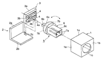
図2は、本発明の折り畳み式電話機に係わる回転型コネクタ付スイッチを示す斜視図、図3は、本発明の折り畳み式電話機に係わる回転型コネクタ付スイッチを示す正面図、図4は、本発明の折り畳み式電話機に係わる回転型コネクタ付スイッチを示す分解斜視図、図5は、図4に示す回転型コネクタ付スイッチの枠体を示す斜視図である。
【0034】
図2〜図5に示すように、枠体1は、金属板から成り、切断・折り曲げ加工にて略矩形に形成され、U字形状の側壁1aと、略中央部に円形の孔1cが形成され、前記側壁1aを繋ぐ前面壁1bとを備えている。また、枠体1の下面側と後面側とは、解放されている。
【0035】
取付部材2は、絶縁性の合成樹脂材料を成形加工して略L字形に形成され、矩形の後面壁2aと、該後面壁2aと直交する方向に形成された下壁2bと、該下壁2bの一方の側端面側に設けられた、矩形の複数個(例えば2個)の孔2c、2cとを備えている。
また、この取付部材2は、後面壁2aと下壁2bとで、枠体1の解放面を塞ぐように枠体1に結合されている。
【0036】
絶縁板3は、絶縁性の合成樹脂材料を成形加工にて略矩形に形成された接点部受け3aと、該接点部受け3aの略中央部に形成された円形の孔3bとを有している。
また、一対の接点部4は、弾性を有する平板状の金属材料から成り、接点部受け3aの前面側に配設されている。また、接点部4の中間部は、接点部受け3aにインサート成形加工によって埋設され、一方の端部には、端子4aが設けられ、他方の端部は、自由端となっており、接点部片4bが設けられている。また、端子4aは、接点部受け3aの下方の端面から外方に突出されている。
【0037】
また、この絶縁板3は、取付部材2の後面壁2aに重ねられた位置であって、接点部4の端子4a、4aが、取付部材2の孔2c、2cに挿通されて、外方に突出した状態で絶縁板3の下端面が取付部材2の下壁2b上に配設されている。
【0038】
第一コネクタ部5は、絶縁性の合成樹脂材料を成形加工した保持部材6と、保持部材6に取り付けられた雄型のコネクタ端子7aと、該コネクタ端子7aに接続された状態で、保持部材6の背面に形成された可動接点部7bとを備えている。
また、保持部材6は、円板状の鍔部6aと、該鍔部6aの一方の平面(背面)側の中央部に配設され、外方に突出された矩形の軸部6bと、鍔部6aの他方の平面(前面)側に配設され、外方に突出された矩形の筒状で先端部が開口された筒部6cとから成る。
また、雄型のコネクタ端子7aは、筒部6c内に配設され、可動接点部7bは、前記鍔部6aの背面の周縁部に略扇状に配設されている。
【0039】
そして、保持部材6の筒部6cは、枠体1の前面壁1bに配設された孔1cに挿通されて、枠体1から外方に突出された状態で配設され、保持部材6の軸部6bは、絶縁板3の孔3bに挿通された状態で配設されている。この状態で第一コネクタ部5は、枠体1に対して所定の回動範囲で回動自在に配設されている。
また、保持部材6の鍔部6aに配設された一対の可動接点部7b、7bと、絶縁板3に配設された一対の接点部4、4とは、対向して配設されている。
【0040】
また、この状態では、絶縁板3に設けられた接点部4、4の接点部片4b、4bに対して、第一コネクタ部5の可動接点部7b、7bが所定の回動角度(例えば、約135度)に回動された状態のとき、接点部片4b、4bと可動接点部7b、7bとが、それぞれ接触され、オフの状態からオンの状態になるように配設されている。そして、更に第一コネクタ部5は、回動(例えば、約180度まで)でき、この回動の状態ではオンの状態が維持される。また、この状態から第一コネクタ部5を元に戻す方向に回動させると、所定の回動角度で可動接点部7b、7bが接点部片4b、4bからそれぞれ離れて、オンの状態からオフの状態になる。
この回転型コネクタ付スイッチCが第一のケースに組み込まれると、図2に示すように第一コネクタ部5のコネクタ端子7aは、第二コネクタ部33のコネクタ端子33aと結合されている。
【0041】
即ち、回転型コネクタ付スイッチCのスイッチ部Dは、第一コネクタ部5に設けた可動接点部7bと、該可動接点部7bに接離する接点部4を設けた絶縁板3とで構成されている。
そして、上述したように、回転型コネクタ付スイッチCは、コネクタ端子7aを有する回転型の第一コネクタ部5と、スイッチ部Dとで構成されおり、枠体1と取付部材2とで、絶縁板3、可動接点部7b、及び接点部4を覆うように構成されている。
【0042】
次に、この回転型コネクタ付スイッチCの動作について説明する。
図3に示すように、本発明の回転型コネクタ付スイッチCは、枠体1に対して第一コネクタ部5が所定の回動範囲の回動をするように構成されている。そして、例えば、0度〜約135度の回動範囲では、この回転型コネクタ付スイッチCのスイッチ部Dは、オフ(OFF)の状態であって、第一コネクタ部5の可動接点部7bと絶縁板3の接点部4とが離れており、次の約135度〜約180度の回動範囲では、このスイッチ部Dは、オンの状態に成り、第一コネクタ部5の可動接点部7bと絶縁板3の接点部4とが接続されるように配設されている。
【0043】
そして、上述のような回転型コネクタ付スイッチCは、第一のケース21に組み込まれ、また、第二コネクタ部33は、第二のケース31に組み込まれて、第一のケース21と第二のケース31とが組み合わされると同時に、第一コネクタ部5と第二コネクタ部33とが結合されると、この折り畳み式電話機が構成され、その動作について説明する。
先ず、この折り畳み式電話機を使用しないときは、第一のケース21内にアンテナ22は収納され、且つ、第一のケース21と第二のケース31とは折り畳まれて、第一のケース21の正面壁21eと第二のケース31の正面壁31eとが組み合わされて、閉じられた状態に保持されている。この状態のとき、第一のケース21に配設された回転型コネクタ付スイッチCは、オフの状態である。
【0044】
そして、この折り畳み式電話機を使用するときは、第一のケース21内のアンテナ22を外方に引き出すと共に、折り畳まれた(閉じられた)第二のケース31を矢印A方向に、例えば、約180度位回動させて第二のケース31を第一のケース21から開くようにする。この第二のケース31の回動によって、第二のケース31の第二コネクタ部33が回動され、この第二コネクタ部33の回動で、第二コネクタ部33と結合された第一のケース21に配設された回転型コネクタ付スイッチCの第一コネクタ部5は回動し、第一コネクタ部5の回動で回転型コネクタ付スイッチCは、オンの状態になる。
【0045】
そしてまた、回転型コネクタ付スイッチCのスイッチ部Dがオンの状態になると、第一のケース21の音声信号変換回路部26と、第二のケース31の送話部32とは、結合された第一コネクタ部5と、第二コネクタ部33とを介して電気的に接続されている。
また、スイッチ部Dがオンの状態に切り換わると、このオンの状態を検知して、この第一のケース21の電源回路部29がオンの状態に切り換えられ、折り畳み式電話機が使用可能である状態となる。
【0046】
次に、本発明の折り畳み式電話機に係わる回転型コネクタ付スイッチの第二の実施の形態について説明する。図6は、本発明の折り畳み式電話機に係わる回転型コネクタ付スイッチの第二の実施の形態を示す斜視図、図7は、本発明の折り畳み式電話機に係わる回転型コネクタ付スイッチの第二の実施の形態を示す分解斜視図である。この第二の実施の形態の回転型コネクタ付スイッチは、スイッチ部が2段(2回路)の構成であって、スイッチ部が1段(1回路)の構成である前述の第一の実施の形態と異なるが、基本的な構成は、前記第一の実施の形態とほぼ同様である。
【0047】
図6、図7に示すように、この回転型コネクタ付スイッチは、いわゆるスイッチ部が2段(2回路)の構成であり、その外形は第一の実施の形態と比較して、枠体の奥行きが長く形成されている。
【0048】
そして、枠体17は、金属板から成り、切断・折り曲げ加工にて略矩形に形成され、U字形状の側壁17aと、略中央部に円形の孔17cが形成され、前記側壁7aを繋ぐ前面壁17bとを備えている。また、枠体17の下面側と後面側とは、解放されている。
【0049】
取付部材8は、絶縁性の合成樹脂材料を成形加工して略L字形に形成され、矩形の後面壁8aと、該後面壁8aと直交する方向に形成された下壁8bと、前記後面壁8aに平行であって、下壁8bの中間部から上方に突出した仕切壁8dとを有している。下壁8bの一方の側端面側には、仕切壁8dを間にしてそれぞれ矩形の複数個(例えば2個づつ)の孔8cが配設されている。また、仕切壁8dの高さは、後面壁8aの高さに比べて低く形成されている。
また、この取付部材8は、後面壁8aと下壁8bとで、枠体17の解放面を塞ぐように枠体17に結合されている。
【0050】
第二絶縁板9は、絶縁性の合成樹脂材料を成形加工にて略矩形に形成された接点部受け9aと、該接点部受け9aの略中央部に形成された円形の孔9bとを有している。
また、一対の第二接点部10は、弾性を有する金属板から成り、前記接点部受け9aの前面側に配設され、第二接点部10の中間部は、接点部受け9aにインサート成形加工によって埋設され、一方の端部には、端子10aが設けられ、他方の端部は、自由端となっており、接点部片10bが設けられている。また、端子10aは、接点部受け9aの下方の端面から外方に突出されている。
【0051】
また、この第二絶縁板9は、取付部材8の後面壁8aに重ねられた位置であって、第二接点部10、10の端子10a、10aが、取付部材8の孔8c、8cにそれぞれ挿通されて、外方に突出した状態で第二絶縁板9の下端面が取付部材8の下壁8b上に配設されている。
【0052】
回動部材11は、絶縁性の合成樹脂材料に、成形加工して円板状に形成され、その略中央部には、矩形の孔11aが配設されている。また、回動部材11の平面(背面)側の周縁部に配設された金属板から成る略扇状の第二可動接点部11bが配設されている。
そして、回動部材11の第二可動接点部11bは、回動部材11の回動によって、第二絶縁板9の第二接点部10と接離するように対向して配設されている。また、回動部材11と、該回動部材11に設けた第二可動接点部11bと、該第二可動接点部11bに接離する第二接点部10とによって、第二のスイッチ部が構成される。
【0053】
また、第一絶縁板12は、その構成が前述の第二絶縁板9と同様であるので詳細な説明は省略する。
そして、第一絶縁板12は、接点部受け12aと、孔12bとを有している。また、一対の第一接点部13は、端子13aと、接点部片13bとを有し、第一接点部13の中間部は、第一絶縁板12の接点部受け12aに埋設された状態で配設されている。
そして、この第一絶縁板12は、取付部材8の後面壁8aに平行であって、仕切壁8dに重ね合わされて、第一絶縁板12の端子13a、13aが、取付部材8の孔8c、8cに挿通された状態で、第一絶縁板12の下端面が取付部材8の下壁8b上に配設されている。
【0054】
第一コネクタ部14は、絶縁性の合成樹脂材料を成形加工した保持部材15と、該保持部材15に取り付けられた雄型のコネクタ端子16aと、該コネクタ端子16aに接続された状態で、保持部材15の背面に形成された第一可動接点部16bとを備えている。
また、保持部材15は、円板状の鍔部15aと、該鍔部15aの後面側の中央部に配設され、外方に突出された断面が矩形の軸部15bと、鍔部15aの前面側に配設され、外方に突出された矩形の筒状で先端部が開口された筒部15cとから成る。
また、雄型のコネクタ端子16aは、筒部15c内に収納され、第一可動接点部16bは、鍔部15aの背面側の周縁部に略扇状に配設されている。
【0055】
そして、保持部材15の筒部15cは、前記枠体17の前面壁17bに配設された孔17cに挿通されて、枠体17から外方に突出された状態で配設され、この状態で第一コネクタ部14が、枠体17に対して所定の回動範囲で回動自在に配設されている。
また、前記保持部材15の軸部15bの長さは、前述の第一の実施の形態の回転型コネクタ付スイッチの第一コネクタ部5の軸部6bの長さよりも長く形成されている。
【0056】
また、保持部材15の軸部15bは、第一絶縁板12の孔12bと、回動部材11の孔11aと、第二絶縁板9の孔9bとを挿通して配設され、第一コネクタ部14に設けた保持部材15の回動によって、回動部材11が共に回動されるように配設されている。
また、保持部材15の鍔部15aの背面に配設された第一可動接点部16bと、第一絶縁板12に配設された第一接点部13とは、保持部材15の回動によって接離されるように配設されている。
そして、第一コネクタ部14に設けた第一可動接点部16bと、該第一可動接点部16bに接離する第一接点部13とで第一スイッチ部が構成されている。
【0057】
また、上述の如き構成の回転型コネクタ付スイッチは、第一絶縁板12と第二絶縁板9とを保持する取付部材8と、第一絶縁板12と第二絶縁板9との上部を覆う枠体17とを備え、取付部材8を枠体17と結合させて、枠体17と取付部材8とで第一絶縁板12と第二絶縁板9とを覆うように構成されている。
【0058】
そして、上述の如き構成の回転型コネクタ付スイッチは、第一コネクタ部14と、第一コネクタ部14の回動によって切り換えられる第一スイッチ部と、第一コネクタ部14の回動によって切り換えられる第二スイッチ部とを備えており、第一コネクタ部14の第一可動接点部16bが所定の回動角度(例えば、約120度)に回動された状態のとき、第一可動接点部16bと第一接点部13とが当接され、且つ、第一コネクタ部14の回動によって、回動部材11が回動され、この回動で回動部材11の第二可動接点部11bと第二接点部10とが接触され、それぞれオフの状態からオンの状態に切り換えられる。そして、第一コネクタ部14は、更に回動(例えば、180度まで)でき、そして、これ以降は、オンの状態が維持される。また、この状態から、第一コネクタ部14を元に戻す方向に回動させると、所定の回動角度で、第一可動接点部16bと第一接点部13、及び第二可動接点部11bと第二接点部10がそれぞれ離れて、オンの状態からオフの状態に切り換えられる。
【0059】
次に、この回転型コネクタ付スイッチの動作は、基本的には、前述の第一の実施の形態の回転型コネクタ付スイッチの動作と同様であることから説明は省略する。
また、この回転型コネクタ付スイッチは、前述の折り畳み式電話機の第一のケース21に配設されて、ケースの開閉時に、第一スイッチ部と第二スイッチ部とが切り換えられるように構成されている。また、このとき回転型コネクタ付スイッチの第一コネクタ部14は、前記第二のケース31に配設された前記第二コネクタ部33と着脱可能に結合されている。
【0060】
そして、第一スイッチ部は、前記第一のケース21に配設された、前記音声信号変換回路26と接続されており、第二スイッチ部は、前記電源回路部29と接続されていて、第一スイッチ部の接離によって、音声信号変換回路26と送話部32との接離(オン・オフ)が行われ、また、第二スイッチ部の接離によって、電源回路部29の接離(オン・オフ)が行われる。このことから、折り畳み式電話機の電源が入るのは、第二のケース31が開かれて、所定の回動角度以上の第一コネクタ部14の回動が行われた状態のときである。
【0061】
また、第一コネクタ部14の回動によって、スイッチ部がオンの状態になる回動角度は、第一、第二の実施の形態において、約135度又は、約120度であることの説明をしたが、これらの回動角度に限定されることはなく、充分にケースが開かれた状態である所望の回動角度(例えば、120度以上)以上でオンの状態になるように可動接点部を配設すれば良い。
【0062】
【発明の効果】
以上のように、本発明の折り畳み式電話機は、一方のケースと、該一方のケースに配設され、コネクタ端子を有する回転型の第一コネクタ部とスイッチ部とを有する回転型コネクタ付スイッチと、他方のケースと、該他方のケースに配設され、コネクタ端子を有する第二コネクタ部とを備え、第一コネクタ部と前記第二コネクタ部とが着脱可能に結合されると共に、一方のケースと他方のケースとが着脱可能に組み合わされて、一方のケースと他方のケースとが折り畳み式に開閉出来ることから、他方のケースが、容易に一方のケースから着脱出来、且つ交換出来るので、デザイン上、融通性がある折り畳み式電話機を提供するという効果を奏する。
【0063】
また、本発明の折り畳み式電話機は、何れか一方のケースの開閉で、第一コネクタ部と第二コネクタ部とが共に回動し、第一コネクタ部の回動によって、回転型コネクタ付スイッチのスイッチ部が切り替えられることから、一方のケースを開閉することだけでスイッチ部の切り替えが出来、操作性が向上する。
【0064】
また、本発明の折り畳み式電話機は、ケースの折り畳み式に開閉する回動中心に、第一コネクタ部と第二コネクタ部との回動中心が配設されていることから、第一コネクタ部と第二コネクタ部との回動に無理な力が掛かることなく、安定した第一コネクタ部と第二コネクタ部との回動が行われる。
【0065】
また、本発明の折り畳み式電話機は、何れか一方のケースが約120度以上開かれた時、スイッチ部が切り替えられることから、折り畳み式電話機が、時として、例えば半開き状態に保持されてもスイッチ部が切り替えられないことから、折り畳み式電話機の電源がオンとなる通話動作状態にはならず、無駄な電力を使うことなく、長時間の使用が可能な折り畳み式電話機を提供できる。
【0066】
また、本発明の折り畳み式電話機は、一方のケースには、回転型コネクタ付スイッチのスイッチ部と接続された音声信号変換回路部が配設され、他方のケースには、第二コネクタ部と接続された送話部が配設され、第一コネクタ部と第二コネクタ部とが電気的に結合されていることから、送話部が配設された他方のケースが、容易に音声信号変換回路部が配設された一方のケースから着脱出来、且つ交換も出来るので、デザイン上、融通性がある折り畳み式電話機を提供するという効果を奏する。
【0067】
また、本発明の折り畳み式電話機は、スイッチ部は、第一コネクタ部に設けた可動接点部と、該可動接点部に接離する接点部を設けた絶縁板とで構成したことから、回動する第一コネクタ部に可動接点部を配設したので、可動接点部を可動させる別部材を必要とせずに、構成が簡単なスイッチ部を提供できる。
【0068】
また、本発明の折り畳み式電話機は、絶縁板を保持する取付部材を備え、該取付部材を枠体と結合させて、枠体と取付部材とで絶縁板を覆うようにしたことから絶縁板に設けた接点部に対する防塵効果が向上する。
【0069】
また、本発明の折り畳み式電話機は、回転型コネクタ付スイッチは、回転型の第一コネクタ部と、該第一コネクタ部の回動によって切り換えられる第一スイッチ部と、第二スイッチ部とを備えていることから、スイッチ切り換えの接点数が増加するので、この増えた接点数によって、多数の機能を確実に切り換えることが出来る。
【0070】
また、本発明の折り畳み式電話機は、第一スイッチ部は、前記第一コネクタ部に設けた第一可動接点部と、該第一可動接点部に接離する第一接点部とから成り、第二スイッチ部は、回動部材と、該回動部材に設けた第二可動接点部と、該第二可動接点部に接離する第二接点部とから成り、回動部材が、第一コネクタ部によって回動されて、第一スイッチ部と第二スイッチ部との切換えを行うようにしたことから、第一スイッチ部と第二スイッチ部とが第一コネクタ部の回動によって、同時に切り換えられるので、構成が簡単で安価に提供ができる。
【0071】
また、本発明の折り畳み式電話機は、第一コネクタ部は、絶縁材から成り、回転可能な保持部材と、該保持部材に取り付けられコネクタ端子と、保持部材の背面に設けられた第一可動接点部とから成り、第一スイッチ部は、第一可動接点部と、該第一可動接点部に接離する第一接点部と、該第一接点部を取り付けた第一絶縁板とから成り、第二スイッチ部は、回動部材と、該回動部材に設けた第二可動接点部と、第二可動接点部に接離する第二接点部と、該第二接点部を取り付けた第二絶縁板とから成り、保持部材に設けられた軸部を、第一絶縁板の孔に貫通させ、軸部を介して回動部材を回転させるようにしたことから、少ない構成部材にて組立られているので、安価に提供できる。
【図面の簡単な説明】
【図1】本発明の折り畳み式電話機の実施の形態を示す分解斜視図である。
【図2】本発明の折り畳み式電話機に係わる回転型コネクタ付スイッチの第一の実施の形態を示す斜視図である。
【図3】本発明の折り畳み式電話機に係わる回転型コネクタ付スイッチの第一の実施の形態を示す正面図である。
【図4】本発明の折り畳み式電話機に係わる回転型コネクタ付スイッチの第一の実施の形態を示す分解斜視図である。
【図5】図4に示す回転型コネクタ付スイッチの筺体を示す斜視図である。
【図6】本発明の折り畳み式電話機に係わる回転型コネクタ付スイッチの第二の実施の形態を示す斜視図である。
【図7】本発明の折り畳み式電話機に係わる回転型コネクタ付スイッチの第二の実施の形態を示す分解斜視図である。
【図8】従来の折り畳み式電話機を示す斜視図である。
【符号の説明】
1、17 枠体
1c、17c 孔
2、8 取付部材
3 絶縁板
3b 孔
4 接点部
4a、10a、13a 端子
4b、10b、13b 接点部片
5、14 第一コネクタ部
6、15 保持部材
6b、15b 軸部
7a、16a、33a コネクタ端子
7b、16b 可動接点部(第一可動接点部)
9 第二絶縁板
9b 孔
10 第二接点部
11 回動部材
11a 孔
11b 第二可動接点部
12 第一絶縁板
12b 孔
13 第一接点部
21 第一のケース
26 音声信号変換回路
29 電源回路部
31 第二のケース(フリップ)
32 送話部
33 第二コネクタ部
C 回転型コネクタ付スイッチ
D スイッチ部[0001]
BACKGROUND OF THE INVENTION
The present invention relates to a foldable telephone, for example, a foldable telephone in which a flip (cover) in which a microphone of a portable foldable telephone is disposed is removable from a main body.
[0002]
[Prior art]
Here, a conventional folding telephone will be described with reference to the drawings.
FIG. 8 is a perspective view showing a conventional folding telephone.
As shown in FIG. 8, the foldable telephone includes a
[0003]
The
Further, in the
On the
[0004]
The
[0005]
The
[0006]
And the
Such conventional portable foldable telephones are rapidly spreading because of demands such as ease of carrying around due to miniaturization and convenience. Since this foldable telephone needs to satisfy a predetermined function, there are many restrictions on its structure and design, and it has been impossible to replace the flip (cover) freely. Among them, the current situation is that they are differentiated by sticking a sticker on a flip that covers the main body of the foldable telephone or drawing a picture.
[0007]
In this foldable telephone, when the
[0008]
[Problems to be solved by the invention]
However, in the conventional foldable telephone, the audio signal conversion circuit part of the first case (main body part) and the transmission part (microphone) of the second case (flip) are formed on a flexible printed wiring board or the like. Since it is directly connected by a pair of connection lines, the second case cannot be easily attached / detached / replaced from the first case. For this reason, there is a problem that the design is not flexible.
[0009]
Further, in the conventional folding phone, when the second case is slightly opened from time to time, the micro switch of the first case is turned on, and this slightly opened state is maintained. However, there is a problem that the power supply is wasted because the power is turned on even though the folding telephone is not used.
[0010]
Therefore, the foldable telephone of the present invention solves the above-mentioned problems, and its purpose is to easily attach and detach the second case (flip) from the first case (main part) of the foldable telephone. The present invention provides a foldable telephone provided with a second case that can be exchanged and is flexible in design.
[0011]
[Means for Solving the Problems]
The foldable telephone of the present invention includes one case, a switch with a rotary connector that is disposed in the one case and has a rotary first connector portion having a connector terminal and a switch portion, and the other case. A second connector part disposed in the other case and having a connector terminal, The first connector portion is made of an insulating material, and is formed on the back surface of the holding member in a state of being connected to the rotatable holding member, the connector terminal attached to the holding member, and the connector terminal. A movable contact portion, and the switch portion includes the movable contact portion provided in the first connector portion, and a contact portion disposed opposite to the movable contact portion and opposed to the movable contact portion. The first connector portion and the switch portion are coupled to each other by a frame that rotatably holds the holding member and a mounting member that holds the insulating plate. Configure the switch The first connector part and the second connector part Through each other's connector terminals In addition to being detachably coupled, one case and the other case are detachably combined so that the one case and the other case can be folded and opened.
[0012]
Further, the foldable telephone of the present invention comprises the above-mentioned One or the other The first connector part by opening and closing the case Is connected to the second connector portion with respect to the one case. Rotate, and by the rotation of the first connector part, The movable contact portion provided on the first connector portion and the contact portion provided on the insulating plate are separated from each other. The switch part of the switch with the rotary connector is switched.
[0013]
Moreover, the folding telephone of this invention is that the rotation center of a 1st connector part and a 2nd connector part is arrange | positioned in the rotation center which opens and closes the case so that folding is possible.
[0014]
The foldable telephone of the present invention is One or the other Case The opening and closing angle between the facing front walls is folded When opened more than about 120 degrees, By turning the first connector The switch part is switched.
[0015]
In the foldable telephone of the present invention, one case is provided with an audio signal conversion circuit portion connected to the switch portion of the switch with a rotary connector, and the other case is connected to the second connector portion. And the first connector portion and the second connector portion are electrically coupled to each other.
[0019]
The foldable telephone of the present invention is One case, a rotary-type connector-equipped switch having a first connector part having a connector terminal and a switch part, the other case, and the other case. A second connector part having a connector terminal, the switch with a rotary connector, the first connector part of the rotary type, the first switch part switched by the rotation of the first connector part, and the A second switch portion that is switched by rotation of the first connector portion, and the first switch portion includes a first movable contact portion provided in the first connector portion, and a first movable contact portion. The second switch part includes a rotating member, a second movable contact part provided on the rotating member, and a second contact contacting and separating from the second movable contact part. The first connector And the second connector portion are detachably coupled to each other via the connector terminals, and the first switch portion is rotated by the rotation of the first connector portion when the one or the other case is opened or closed. Part is switched, and the rotating member is rotated by the first connector part to switch the second switch part. That is.
[0020]
In the foldable telephone of the present invention, an audio signal conversion circuit unit and a power supply circuit unit are disposed in one case, and the first switch unit of the switch with a rotary connector is connected to the audio signal conversion circuit unit. The second switch part is connected to the power supply circuit part, and the other case is provided with a transmitter part connected to the second connector part, and the first connector part and the second connector part are electrically connected. The first switch portion and the second switch portion are switched when the case is opened and closed.
[0022]
Further, the foldable telephone of the present invention is provided with a first movable contact portion, made of an insulating material, comprising a rotatable holding member having a shaft portion, and an insulating plate having a hole attached to the first contact portion, The shaft portion is protruded through the hole of the insulating plate, and the rotating member is rotated by the protruding shaft portion.
[0023]
In the foldable telephone according to the present invention, the first connector portion is made of an insulating material, the holding member is rotatable, the connector terminal is attached to the holding member, and the first movable contact is provided on the back surface of the holding member. The first switch part is composed of a first movable contact part, a first contact part contacting and separating from the first movable contact part, and a first insulating plate to which the first contact part is attached. The second switch portion includes a rotating member, a second movable contact portion provided on the rotating member, a second contact portion contacting and separating from the second movable contact portion, and a second attached with the second contact portion. The shaft portion formed of the insulating plate and provided in the holding member is passed through the hole of the first insulating plate, and the rotating member is rotated through the shaft portion.
[0024]
The foldable telephone of the present invention includes an attachment member that holds the first insulating plate and the second insulating plate, and a frame that covers the upper portions of the first insulating plate and the second insulating plate. That is, the first insulating plate and the second insulating plate are covered with the frame and the attachment member by being combined with the frame.
[0025]
DETAILED DESCRIPTION OF THE INVENTION
Hereinafter, embodiments of a foldable telephone according to the present invention will be described with reference to the drawings.
FIG. 1 is an exploded perspective view showing a foldable telephone according to the present invention.
As shown in FIG. 1, the foldable telephone has a
[0026]
The
The
[0027]
On the
Further, the rotary connector switch C is disposed in the vicinity of the
[0028]
The
[0029]
The
[0030]
The
At this time, the
[0031]
When the
Then, when the
[0032]
In the foldable telephone set switched to the ON state, the audio signal
In the foldable telephone switched to the on state, the switch circuit D is detected to be switched on, and the power
[0033]
The first embodiment of the switch with a rotary connector relating to the foldable telephone of the present invention as described above will be described with reference to the drawings.
2 is a perspective view showing a switch with a rotary connector according to the foldable telephone of the present invention, FIG. 3 is a front view showing the switch with a rotary connector according to the foldable telephone of the present invention, and FIG. FIG. 5 is a perspective view showing a frame of the switch with a rotary connector shown in FIG. 4.
[0034]
As shown in FIGS. 2 to 5, the
[0035]
The mounting
Further, the
[0036]
The insulating plate 3 has a
Further, the pair of
[0037]
Further, the insulating plate 3 is a position overlapped with the
[0038]
The
The holding member 6 includes a disc-shaped
The
[0039]
The
Further, the pair of
[0040]
Further, in this state, the
When the switch C with the rotary connector is assembled in the first case, the
[0041]
That is, the switch part D of the switch with a rotary connector C is composed of a
As described above, the switch C with the rotary connector is composed of the rotary
[0042]
Next, the operation of the rotary connector-attached switch C will be described.
As shown in FIG. 3, the switch with a rotary connector C of the present invention is configured such that the
[0043]
The rotary connector-equipped switch C as described above is incorporated in the
First, when this foldable telephone is not used, the
[0044]
When using this foldable telephone, the
[0045]
When the switch part D of the rotary connector-attached switch C is turned on, the audio signal
Further, when the switch part D is switched to the on state, the on state is detected and the power
[0046]
Next, a second embodiment of the switch with a rotary connector relating to the foldable telephone of the present invention will be described. FIG. 6 is a perspective view showing a second embodiment of the switch with a rotary connector according to the foldable telephone of the present invention, and FIG. 7 shows the second embodiment of the switch with a rotary connector according to the foldable telephone of the present invention. It is a disassembled perspective view which shows embodiment. The switch with a rotary connector according to the second embodiment has a two-stage (two circuits) switch section and a first-stage (one circuit) switch section. Although different from the embodiment, the basic configuration is substantially the same as that of the first embodiment.
[0047]
As shown in FIG. 6 and FIG. 7, this switch with a rotary connector has a so-called switch portion having two stages (two circuits), and its outer shape is that of the frame compared to the first embodiment. The depth is long.
[0048]
The
[0049]
The mounting
Further, the
[0050]
The second insulating plate 9 has a
The pair of
[0051]
Further, the second insulating plate 9 is a position overlapped with the
[0052]
The rotating
The second movable contact portion 11 b of the rotating
[0053]
The first insulating
And the 1st insulating
The first insulating
[0054]
The
In addition, the holding
Further, the
[0055]
The
The length of the
[0056]
Further, the
Further, the first
And the 1st switch part is comprised by the 1st
[0057]
Moreover, the switch with a rotary connector having the above-described configuration covers the mounting
[0058]
The switch with a rotary connector having the above-described configuration includes the
[0059]
Next, since the operation of the switch with a rotary connector is basically the same as the operation of the switch with a rotary connector of the first embodiment described above, description thereof is omitted.
Further, the switch with a rotary connector is arranged in the
[0060]
The first switch unit is connected to the audio
[0061]
In addition, in the first and second embodiments, the rotation angle at which the switch unit is turned on by the rotation of the
[0062]
【The invention's effect】
As described above, the foldable telephone according to the present invention includes one case, a rotary connector-equipped switch that is disposed in the one case and has a rotary first connector portion having a connector terminal and a switch portion. A second connector part having a connector terminal, the first connector part and the second connector part being detachably coupled to each other, and one case And the other case are detachably combined, and one case and the other case can be opened and closed in a foldable manner, so the other case can be easily detached from the one case and can be replaced. In addition, there is an effect of providing a foldable telephone having flexibility.
[0063]
Further, the folding telephone of the present invention is such that when the opening and closing of one of the cases, the first connector portion and the second connector portion rotate together, and the rotation of the first connector portion causes the rotation of the switch with a rotary connector. Since the switch part is switched, the switch part can be switched only by opening and closing one case, and the operability is improved.
[0064]
Further, the folding phone of the present invention has the first connector portion and the second connector portion at the center of rotation that opens and closes the case in a foldable manner. Stable rotation of the first connector portion and the second connector portion is performed without applying an excessive force to the rotation of the second connector portion.
[0065]
In addition, the foldable telephone according to the present invention can be switched even if the foldable telephone is sometimes held in a half-open state, for example, because the switch part is switched when one of the cases is opened about 120 degrees or more. Therefore, it is possible to provide a foldable telephone that can be used for a long time without using wasted power.
[0066]
In the foldable telephone of the present invention, one case is provided with an audio signal conversion circuit portion connected to the switch portion of the switch with a rotary connector, and the other case is connected to the second connector portion. Since the first connector portion and the second connector portion are electrically coupled to each other, the other case in which the transmitter portion is disposed is easily connected to the audio signal conversion circuit. Since the case can be attached / detached and exchanged from one case where the portion is disposed, there is an effect of providing a foldable telephone having flexibility in design.
[0067]
In the foldable telephone according to the present invention, the switch portion is composed of a movable contact portion provided in the first connector portion and an insulating plate provided with a contact portion that contacts and separates from the movable contact portion. Since the movable contact portion is disposed in the first connector portion, the switch portion having a simple configuration can be provided without requiring a separate member for moving the movable contact portion.
[0068]
Further, the foldable telephone according to the present invention includes an attachment member for holding the insulating plate, and the attachment member is coupled to the frame body so that the frame plate and the attachment member cover the insulation plate. The dustproof effect for the provided contact portion is improved.
[0069]
The foldable telephone according to the present invention includes a rotary connector-attached switch including a rotary first connector portion, a first switch portion that is switched by rotation of the first connector portion, and a second switch portion. Therefore, since the number of contacts for switching the switch increases, a large number of functions can be switched reliably with the increased number of contacts.
[0070]
Further, in the foldable telephone of the present invention, the first switch part is composed of a first movable contact part provided in the first connector part and a first contact part contacting and separating from the first movable contact part. The two switch part includes a rotating member, a second movable contact part provided on the rotating member, and a second contact part contacting and separating from the second movable contact part, and the rotating member is a first connector. Since the first switch portion and the second switch portion are switched by being rotated by the first switch portion, the first switch portion and the second switch portion are simultaneously switched by the rotation of the first connector portion. Therefore, the configuration is simple and can be provided at low cost.
[0071]
In the foldable telephone according to the present invention, the first connector portion is made of an insulating material, the holding member is rotatable, the connector terminal is attached to the holding member, and the first movable contact is provided on the back surface of the holding member. The first switch part is composed of a first movable contact part, a first contact part contacting and separating from the first movable contact part, and a first insulating plate to which the first contact part is attached. The second switch portion includes a rotating member, a second movable contact portion provided on the rotating member, a second contact portion contacting and separating from the second movable contact portion, and a second attached with the second contact portion. Since the shaft portion provided on the holding member is made to pass through the hole of the first insulating plate and the rotating member is rotated through the shaft portion, it is assembled with few components. Therefore, it can be provided at low cost.
[Brief description of the drawings]
FIG. 1 is an exploded perspective view showing an embodiment of a folding telephone according to the present invention.
FIG. 2 is a perspective view showing a first embodiment of a switch with a rotary connector according to the folding telephone of the present invention.
FIG. 3 is a front view showing a first embodiment of a switch with a rotary connector according to the folding telephone of the present invention.
FIG. 4 is an exploded perspective view showing a first embodiment of a switch with a rotary connector according to the folding telephone of the present invention.
5 is a perspective view showing a casing of the switch with a rotary connector shown in FIG. 4. FIG.
FIG. 6 is a perspective view showing a second embodiment of a switch with a rotary connector according to the foldable telephone of the present invention.
FIG. 7 is an exploded perspective view showing a second embodiment of the switch with a rotary connector according to the folding telephone of the present invention.
FIG. 8 is a perspective view showing a conventional folding telephone.
[Explanation of symbols]
1,17 frame
1c, 17c hole
2, 8 Mounting member
3 Insulation plate
3b hole
4 Contact part
4a, 10a, 13a terminals
4b, 10b, 13b Contact piece
5, 14 First connector part
6, 15 Holding member
6b, 15b Shaft
7a, 16a, 33a Connector terminal
7b, 16b Movable contact part (first movable contact part)
9 Second insulation plate
9b hole
10 Second contact
11 Rotating member
11a hole
11b Second movable contact portion
12 First insulation plate
12b hole
13 First contact
21 First case
26 Audio signal conversion circuit
29 Power supply circuit
31 Second case (flip)
32 Speaker
33 Second connector part
C Switch with rotary connector
D Switch part
Claims (10)
Priority Applications (3)
| Application Number | Priority Date | Filing Date | Title |
|---|---|---|---|
| JP03705998A JP3713378B2 (en) | 1998-02-19 | 1998-02-19 | Folding phone |
| EP99300602A EP0938219A3 (en) | 1998-02-19 | 1999-01-27 | Collapsible telephone set |
| CN 99100638 CN1118174C (en) | 1998-02-19 | 1999-02-09 | Foldable telephone set |
Applications Claiming Priority (1)
| Application Number | Priority Date | Filing Date | Title |
|---|---|---|---|
| JP03705998A JP3713378B2 (en) | 1998-02-19 | 1998-02-19 | Folding phone |
Publications (2)
| Publication Number | Publication Date |
|---|---|
| JPH11234376A JPH11234376A (en) | 1999-08-27 |
| JP3713378B2 true JP3713378B2 (en) | 2005-11-09 |
Family
ID=12487002
Family Applications (1)
| Application Number | Title | Priority Date | Filing Date |
|---|---|---|---|
| JP03705998A Expired - Fee Related JP3713378B2 (en) | 1998-02-19 | 1998-02-19 | Folding phone |
Country Status (3)
| Country | Link |
|---|---|
| EP (1) | EP0938219A3 (en) |
| JP (1) | JP3713378B2 (en) |
| CN (1) | CN1118174C (en) |
Families Citing this family (3)
| Publication number | Priority date | Publication date | Assignee | Title |
|---|---|---|---|---|
| JP3200585B2 (en) * | 1998-02-10 | 2001-08-20 | 富士通株式会社 | Mobile phones and information communication adapters |
| EP1175070A1 (en) * | 2000-07-18 | 2002-01-23 | Telefonaktiebolaget L M Ericsson (Publ) | An electronic device with electrically connected hinged parts |
| DE10305090A1 (en) * | 2003-02-07 | 2004-08-19 | Siemens Ag | Interchangeable housing part with a sensor element |
Family Cites Families (6)
| Publication number | Priority date | Publication date | Assignee | Title |
|---|---|---|---|---|
| US4863387A (en) * | 1987-12-22 | 1989-09-05 | Snaper Alvin A | Printer circuit board separable connector |
| JPH067594Y2 (en) * | 1988-03-31 | 1994-02-23 | アンプ インコーポレーテッド | Electric hinge connector |
| KR940009372B1 (en) * | 1990-07-31 | 1994-10-07 | 미쓰미 덴끼 가부시끼가이샤 | Connector comprising plug and socket which are rotatably engaged with each other |
| CA2078233A1 (en) * | 1991-03-28 | 1992-09-29 | Thomas E. Paulick | Hinge apparatus for foldable radiotelephones |
| US5117073A (en) * | 1991-04-02 | 1992-05-26 | Motorola, Inc. | Control signal initiator responsive to a hinge position |
| JP2550914B2 (en) * | 1994-06-21 | 1996-11-06 | 日本電気株式会社 | Foldable mobile phone device |
-
1998
- 1998-02-19 JP JP03705998A patent/JP3713378B2/en not_active Expired - Fee Related
-
1999
- 1999-01-27 EP EP99300602A patent/EP0938219A3/en not_active Withdrawn
- 1999-02-09 CN CN 99100638 patent/CN1118174C/en not_active Expired - Fee Related
Also Published As
| Publication number | Publication date |
|---|---|
| CN1231557A (en) | 1999-10-13 |
| EP0938219A2 (en) | 1999-08-25 |
| CN1118174C (en) | 2003-08-13 |
| JPH11234376A (en) | 1999-08-27 |
| EP0938219A3 (en) | 2002-04-03 |
Similar Documents
| Publication | Publication Date | Title |
|---|---|---|
| US5732331A (en) | Portable radio having a detachable flip portion | |
| KR100313144B1 (en) | Watch type portable radiotelephone | |
| EP1429347B1 (en) | Strap-shaped input device | |
| US5673314A (en) | Electronic device with door cover speaker actuator and latch mechanism | |
| JP2002281133A (en) | Open and close detection device | |
| KR100386359B1 (en) | Switch having a rotary connector | |
| JP3713378B2 (en) | Folding phone | |
| CN1158835C (en) | Hinge unit for earphone with current transport unit | |
| JP3635195B2 (en) | Mobile phone | |
| TW522417B (en) | Open-close detection apparatus | |
| JP4536042B2 (en) | Keypad assembly and mobile communication terminal including the same | |
| JP2008301125A (en) | Communications device | |
| KR100703394B1 (en) | Interface connector cover opening and shutting apparatus for mobile phone | |
| JP3481512B2 (en) | Open / close detection mechanism of foldable portable communication device | |
| KR100584423B1 (en) | Variable type of cordless telephone | |
| JP2756055B2 (en) | Connector for external interface of wireless terminal | |
| KR20060132343A (en) | Device closing speaker of mobile phone | |
| KR200345352Y1 (en) | Structure for operating the flip door of mobile phone | |
| KR200402969Y1 (en) | Interface connector cover opening and shutting apparatus for mobile phone | |
| JP2001156897A (en) | Portable communication apparatus | |
| JP2002279857A (en) | Opening and closing detection device | |
| JP2001210400A (en) | Disconnecting terminal board | |
| JP2009010765A (en) | Communication device | |
| KR20020078740A (en) | Celluar Phone Associated With Individualized Modules | |
| JP2000224277A (en) | Portable information terminal |
Legal Events
| Date | Code | Title | Description |
|---|---|---|---|
| A977 | Report on retrieval |
Free format text: JAPANESE INTERMEDIATE CODE: A971007 Effective date: 20041210 |
|
| A131 | Notification of reasons for refusal |
Free format text: JAPANESE INTERMEDIATE CODE: A131 Effective date: 20050201 |
|
| A521 | Written amendment |
Free format text: JAPANESE INTERMEDIATE CODE: A523 Effective date: 20050328 |
|
| TRDD | Decision of grant or rejection written | ||
| A01 | Written decision to grant a patent or to grant a registration (utility model) |
Free format text: JAPANESE INTERMEDIATE CODE: A01 Effective date: 20050802 |
|
| A61 | First payment of annual fees (during grant procedure) |
Free format text: JAPANESE INTERMEDIATE CODE: A61 Effective date: 20050822 |
|
| LAPS | Cancellation because of no payment of annual fees |