JP3708106B2 - Disk unit - Google Patents
Disk unit Download PDFInfo
- Publication number
- JP3708106B2 JP3708106B2 JP2004077345A JP2004077345A JP3708106B2 JP 3708106 B2 JP3708106 B2 JP 3708106B2 JP 2004077345 A JP2004077345 A JP 2004077345A JP 2004077345 A JP2004077345 A JP 2004077345A JP 3708106 B2 JP3708106 B2 JP 3708106B2
- Authority
- JP
- Japan
- Prior art keywords
- axis direction
- bosses
- pair
- disk medium
- boss
- Prior art date
- Legal status (The legal status is an assumption and is not a legal conclusion. Google has not performed a legal analysis and makes no representation as to the accuracy of the status listed.)
- Expired - Fee Related
Links
Images


Description
本発明は、コンパクトディスクプレーヤ等における情報の記録及び/又は再生に用いられ、ディスク状の情報記録媒体に対する情報の書き込み及び/又は読み取りを行うディスク装置に関する。 The present invention relates to a disc apparatus that is used for recording and / or reproducing information in a compact disc player or the like and that writes and / or reads information on a disc-shaped information recording medium.
従来より、ディスク装置において、ディスク状の情報記録媒体(以下、ディスク媒体とする。)を、装置内部の収容位置と装置外部の排出位置との間で搬送するローディング機構を備えたものが知られている(特許文献1を参照)。このようなディスク装置では、搬送されるディスク媒体との干渉を回避するため、ディスク媒体を回転させるターンテーブル及び光ピックアップ等は、上下方向に移動するベース(中間ベースとする。)に取り付けられている。 2. Description of the Related Art Conventionally, a disk device having a loading mechanism for conveying a disk-shaped information recording medium (hereinafter referred to as a disk medium) between a housing position inside the apparatus and a discharge position outside the apparatus is known. (See Patent Document 1). In such a disk device, in order to avoid interference with the disk medium being conveyed, a turntable, an optical pickup, and the like that rotate the disk medium are attached to a base (intermediate base) that moves in the vertical direction. Yes.
このような従来のディスク装置では、中間ベースの両側部に一対の軸部が形成されており、これらの軸部が、ディスク装置の装置ベースに形成された支持部に嵌合している。支持部は、上方に開口した半円形の切り欠きであり、この支持部に対して軸部が上方から嵌合するようになっている。また、支持部の近傍には、軸部を支持部から脱落しないように付勢する付勢機構が設けられている。このように構成されているため、ディスク装置が落下等により衝撃を受けると、その衝撃により支持部及び付勢機構が変形して軸部が支持部から脱落し、その結果、中間ベースに支持されるユニット全体(ターンテーブル及び光ピックアップ等を含む)が装置ベースから脱落するという問題がある。 In such a conventional disk device, a pair of shaft portions are formed on both side portions of the intermediate base, and these shaft portions are fitted to support portions formed on the device base of the disk device. The support portion is a semicircular cutout that opens upward, and the shaft portion is fitted to the support portion from above. Further, an urging mechanism for urging the shaft portion so as not to drop off from the support portion is provided in the vicinity of the support portion. Thus, when the disk device receives an impact due to dropping or the like, the support portion and the urging mechanism are deformed by the impact and the shaft portion is dropped from the support portion, and as a result, is supported by the intermediate base. The entire unit (including the turntable and the optical pickup) is dropped from the apparatus base.
本発明は上記のような課題を解消するためになされたもので、落下等の衝撃によるユニットの脱落を防止できるディスク装置を提供することを目的とする。 The present invention has been made to solve the above-described problems, and an object of the present invention is to provide a disk device that can prevent a unit from dropping due to an impact such as dropping.
本発明に係るディスク装置は、ディスク媒体を保持して回転させるターンテーブルと、ディスク媒体に対する情報の書き込み及び読み取りの少なくとも一方を行う光ピックアップと、これらを支持するトラバースシャーシとを有するトラバースユニットと、ディスク媒体を収容位置と排出位置との間で搬送する搬送手段と、トラバースユニットを収容位置におけるディスク媒体に対して接近及び離間するように回動可能に支持するメインシャーシとを備えている。トラバースシャーシは、回動のための互いに同軸の一対の回動軸を有している。メインシャーシは、搬送手段によるディスク媒体の搬送方向と略平行な方向に開口し、一対の回動軸がディスク媒体の搬送方向と略平行な方向に挿入される一対の溝部と、ディスク媒体の搬送方向と略平行な方向に延在し、一対の回動軸を一対の溝部から脱落しないように位置規制する弾性変形可能な一対の位置規制部材とを有している。一対の位置規制部材のそれぞれが、一対の回動軸を一対の溝部に挿入できるよう位置規制部材を弾性変形させるために操作されるピンを有している。 A disk apparatus according to the present invention includes a turntable that holds and rotates a disk medium, an optical pickup that performs at least one of writing and reading of information to and from the disk medium, and a traverse unit that supports them. Conveying means for conveying the disk medium between the storage position and the discharge position, and a main chassis that rotatably supports the traverse unit so as to approach and separate from the disk medium at the storage position. The traverse chassis has a pair of rotation axes that are coaxial with each other for rotation. The main chassis opens in a direction substantially parallel to the direction of transport of the disk medium by the transport means, a pair of grooves into which the pair of rotation shafts are inserted in a direction substantially parallel to the direction of transport of the disk medium, and transport of the disk medium A pair of elastically deformable position restricting members that extend in a direction substantially parallel to the direction and restrict the position of the pair of rotating shafts so as not to drop out of the pair of groove portions. Each of the pair of position restricting members has a pin that is operated to elastically deform the position restricting member so that the pair of rotation shafts can be inserted into the pair of groove portions.
この発明によれば、各支持部への回動軸の挿入方向が、ディスク媒体の搬送方向と略平行な方向であるため、落下等により最も強い衝撃を受ける方向(ディスク媒体の搬送方向と略直交する方向)の回動軸の脱落を抑制することができ、これによりディスク装置からのトラバースユニットの脱落を防止することができる。また、回動軸を溝部に挿入する際には、ピンを操作することで位置規制部材を弾性変形させることができるため、回動軸の溝部への挿入作業が簡単になる。 According to the present invention, since the insertion direction of the rotation shaft to each support portion is a direction substantially parallel to the transport direction of the disk medium, the direction receiving the strongest impact by dropping or the like (substantially the transport direction of the disk medium). It is possible to suppress the dropping of the rotating shaft in the orthogonal direction, thereby preventing the traverse unit from falling off the disk device. In addition, when the rotation shaft is inserted into the groove portion, the position restricting member can be elastically deformed by operating the pin, so that the operation of inserting the rotation shaft into the groove portion is simplified.
本発明の実施の形態について説明する前に、本発明の技術的背景について説明する。
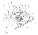
図1は、ディスク装置を示す斜視図である。ディスク装置は、メインシャーシ10と、メインシャーシ10により回動可能に支持されたトラバースシャーシ20と、メインシャーシ10により往復移動可能に支持されたトレイ4とを備えている。トレイ4は、ディスク媒体100を水平に保持する載置面40を有しており、ディスク装置内の収容位置とディスク装置外の排出位置との間で水平に搬送する。
Prior to describing the embodiments of the present invention, the technical background of the present invention will be described.
FIG. 1 is a perspective view showing a disk device. The disk device includes a
以下の説明では、図1に示すように、トレイ4の載置面40に直交する方向をZ軸とし、トレイ4の移動方向をY軸とする。また、Y軸及びZ軸に直交する方向をX軸とする。ここで、Z軸については、トレイ4からディスク媒体100に向かう方向をプラスとし、その反対方向をマイナスとする。Y軸については、トレイ4が排出位置に向かって移動する方向をマイナスとし、その反対方向をプラスとする。X軸については、図1において右上に向かう方向をプラスとし、左下に向かう方向をマイナスとする。なお、図1及び後述する図8は、Z軸方向プラス側が上になるように示されている。これは、ディスク装置がコンパクトディスクプレーヤ等のシステム9(図8)に組み込まれたときの姿勢である。一方、他の図面は、Z軸方向マイナス側が上になるように示されている。これは、メインシャーシ10にトラバースシャーシ20を組み込む作業を行うときの姿勢である。
In the following description, as shown in FIG. 1, the direction orthogonal to the
トラバースシャーシ20には、ターンテーブル30が設けられている。このターンテーブル30は、トラバースシャーシ20に取り付けられたモータ(図示せず)の回転軸に固定されている。ターンテーブル30の上端面には、リング状板金31が固定されている。トレイ4を挟んでメインシャーシ10と反対の側には、クランプ板18が設けられている。クランプ板18は、X軸方向の両端部に形成された一対の脚部18a(図1では一方のみ示す)によりメインシャーシ10に固定されている。クランプ板18のX軸方向中央部には、ターンテーブル30との間でディスク媒体100を挟持するクランパ32が取り付けられている。クランパ32は、その内側に、ターンテーブル30のリング状板金31を磁気的に吸着するためのマグネット33を備えている。
A
トラバースシャーシ20には、ターンテーブル30上で保持されるディスク媒体100に対向するように、光ピックアップ35が設けられている。この光ピックアップ35は、ディスク媒体100に対する情報の書き込み、ディスク媒体100に記録された情報の読み取り、又はその両方を行うものである。ピックアップ35は、トラバースシャーシ20に設けられた図示しないピックアップ駆動機構により、ディスク媒体100の半径方向に移動される。トラバースシャーシ20、ターンテーブル30、光ピックアップ35及びピックアップ駆動機構は、トラバースユニット2を構成する。
The
図2〜図6は、Z軸方向マイナス側を上、Y軸方向プラス側を右下にして示す斜視図である。図2は、トラバースシャーシ20を示す。図3は、トラバースユニット2が取り外された状態のディスク装置を示し、図4は、トラバースユニット2が組み込まれる直前のディスク装置を示す。図5は、トラバースユニット2が組み込まれたディスク装置を示し、図6は、トレイ4が排出位置にあるときのディスク装置を示す。図7は、ディスク装置による効果を模式的に示す概略図であり、Z軸方向マイナス側を上、X軸方向プラス側を右にして示すものである。
2 to 6 are perspective views showing the Z-axis direction minus side as the upper side and the Y-axis direction plus side as the lower right side. FIG. 2 shows the
図2に示すように、トラバースシャーシ20は、Z軸方向に見て略矩形状であり、X軸方向に延びた外周壁201,203と、これら外周壁201,203に直交する外周壁202,204とを有している。外周壁201〜204に囲まれた領域には、各種駆動系を組み込むための装着部205、並びに光ピックアップ35及びピックアップ駆動機構(図示せず)を取り付ける開口部206等が形成されている。外周壁202,204のY軸方向プラス側の端部近傍には、ボス21a,21bがそれぞれ突出形成されている。ボス21a,21bは、外周壁202,204からX軸方向外側に向けて互いに同軸に突出している。図4又は図7に示すように、ボス21a,21bの先端近傍には、Z軸方向のプラス側に突出する突起22a,22bが形成されている。また、ボス21a,21bの根元近傍には、補強板24a,24bが形成されている。
As shown in FIG. 2, the
図3に示すように、メインシャーシ10は、Z軸方向に見て略矩形状であり、X軸方向に延びた外周壁101,103と、Y軸方向に延びた外周壁102,104とを有している。外周壁102,104の内側には、外周壁103からY軸方向マイナス側に延びた一対の側壁11a,11bが形成されている。側壁11aと外周壁102との間には天板105が形成されており、側壁11bと外周壁104との間には天板106が形成されている。
As shown in FIG. 3, the
側壁11a,11bにおいて、ボス21a,21bに対向する位置には、トラバースシャーシ20のボス21a,21bを支持する溝部12a,12bが形成されている。溝部12a,12bは、Z軸方向マイナス側に開口する矩形の切欠きであり、それぞれの内側にボス21a,21bが挿入されるようになっている。また、図5に示すように、溝部12a,12bにボス21a,21bが挿入されると、ボス21a,21bの先端に突出形成された突起22a,22bが側壁11a,11bのX軸方向外側の面に当接可能に対向している。
図4に示すように、溝部12a,12bのX軸方向外側には、弾性爪13a,13bが設けられている。この弾性爪13a,13bは、天板105,106からZ軸方向におけるマイナス側に突出するようそれぞれ形成された長尺部材である。弾性爪13a,13bの先端には、X軸方向内側に突出した突出部14a,14bがそれぞれ形成されている。突出部14a,14bは、ボス21a,21bを溝部12a,12bから脱落しないよう保持する。突出部14a,14bの互いに対向する側の面は、Z軸方向プラス側にいくほどX軸方向内側に突出するような傾斜を有している。この傾斜面よりもさらにZ軸方向プラス側には、XY平面に平行でZ軸方向プラス側を向く水平面が形成されている。溝部12a,12bにボス21a,21bを挿入する際には、ボス21a,21bが突出部14a,14bの傾斜面に当接することにより、弾性爪13a,13bが互いに離間する方向に弾性変形する。ボス21a,21bが突出部14a,14bの間を通過して溝部12a,12b内に挿入されると、弾性爪13a,13bが元の状態に復帰し、上述した水平面によりボス21a,21bを溝部12a,12b内で保持する。なお、側壁11a、溝部12a及び弾性爪13aを、ボス支持部1a(図7)とする。また、側壁11b、溝部12b及び弾性爪13bを、ボス支持部1b(図7)とする。
As shown in FIG. 4,
トラバースシャーシ20の外周壁201には、カムピン23が立設されている。メインシャーシ10の外周壁101の内側には、トラバースシャーシ20のカムピン23に係合するカム溝16を備えたカム部材15が設けられている。このカム部材15は、図示しないカム駆動機構によりX軸方向に往復移動する。このカム部材15の移動に伴って、カムピン23が略Z軸方向に移動し、トラバースシャーシ20がボス21a,21bを中心として回動する。なお、カムピン23は、カム溝16に係合するだけでなく、メインシャーシ10に形成されたZ軸方向に延びた位置決め溝19にも係合し、トラバースシャーシ20のX軸方向における位置決めを行うようになっている。
A
トラバースシャーシ20の回動は、ターンテーブル30や光ピックアップ35と、XY平面内で水平移動するトレイ4(及び搬送されるディスク媒体100)との干渉を回避するために行われる。すなわち、トラバースシャーシ20がXY平面に対して平行になっているときには、ターンテーブル30はディスク媒体100の中心部に係合可能となり、光ピックアップ35はディスク媒体100に対向する。一方、図6に示すようにトレイ4がディスク媒体100を搬送する際には、トラバースシャーシ20はXY平面に対して傾斜しており、この状態では、ターンテーブル30や光ピックアップ35は、トレイ4及びディスク媒体100の移動範囲から下方に退避している。
The
次に、このように構成されたディスク装置の動作について説明する。ディスク媒体100がディスク装置に挿入される前の状態では、トラバースユニット2はXY平面に対して傾斜している。ディスク媒体100をディスク装置に収容する際には、図6に示すように、トレイ4が、図示しないローディング機構によりディスク装置の外部の排出位置まで移動する。次いで、使用者がトレイ4上にディスク媒体100を載せたのち、トレイ4が排出位置からディスク装置内の収容位置まで移動する。次いで、図示しないカム駆動機構によりカム部材15が移動し、これによりトラバースシャーシ20がボス21a,21bを中心に回動し、XY平面に対して平行になる(図1、図5)。次いで、図1に示すように、ターンテーブル30が、トレイ4に保持されたディスク媒体100の中心部に係合する。ターンテーブル30及びクランパ32は、リング状板金31とマグネット33との磁気的な吸引力により、ディスク媒体100を挟持する。ターンテーブル30によりディスク媒体100が回転すると、光ピックアップ35が図示しないピックアップ駆動機構によりディスク媒体100の外周と内周との間で移動し、ディスク媒体100に対する情報の書き込み、読み取り又はその両方が行われる。
Next, the operation of the disk device configured as described above will be described. In a state before the
ディスク媒体100をディスク装置外に排出する際には、カム部材15の移動によりトラバースシャーシ20がボス21a,21bを中心として回動し、XY平面に対して傾斜する。これにより、トラバースシャーシ20に保持されたターンテーブル30及び光ピックアップ35がディスク媒体100から下方に離間する。そののち、図3に示すようにトレイ4が排出位置に移動し、使用者がトレイ4上からディスク媒体100を取り出したのち、ディスク装置内に移動する。
When the
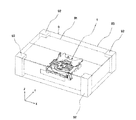
次に、図1〜図8を参照して説明したディスク装置の作用について説明する。まず、搬送時等においてディスク装置が受ける衝撃について説明する。図8は、このディスク装置(図8において符号1で示す)が組み込まれたコンパクトディスクプレーヤ等のシステム9を梱包した状態を示す斜視図であり、Z軸方向プラス側を上、X軸方向プラス側を右下にして示すものである。システム9は、略直方体形状の筐体91を有しており、その水平面(XY平面)における4つのコーナー部分が緩衝材であるクッション92により保持された状態で、段ボール製の梱包箱93に収容されている。
Next, the operation of the disk device described with reference to FIGS. 1 to 8 will be described. First, the impact received by the disk device during transport or the like will be described. FIG. 8 is a perspective view showing a state in which a system 9 such as a compact disc player in which this disc device (indicated by
図9は、図8に示すように梱包されたシステム9を90cmの高さよりコンクリート面に自由落下させた時にディスク装置に生じる加速度(衝撃加速度とする。)を示す図である。図9(a)、(b)及び(C)は、それぞれ、ディスク装置をX軸方向のプラス側、Y軸方向のプラス側、及びZ軸方向のマイナス側に落下させた場合の衝撃加速度の測定値を示す。図9(a)〜(c)において、縦軸には、衝撃加速度をとり、横軸には経過時間をとる。なお、ディスク装置をX軸方向のマイナス側、Y軸方向のマイナス側、及びZ軸方向のプラス側にそれぞれ落下させた場合には、図9(a)〜(c)に対してそれぞれ極性(正負)が反対の波形が得られる。ディスク装置の落下等に伴う衝撃による部品の脱落や破損は、衝撃加速度又は衝撃エネルギー(衝撃加速度と時間の積)の大きさに依存することが知られているが、図9(a)〜(c)より、衝撃加速度及び衝撃エネルギーとも、Z軸方向に落下させた場合に最も大きいことが分かる。これは、衝撃エネルギー及び衝撃加速度が、落下時の接地面に対向する筺体91の表面積にほぼ依存するためと考えられ、ディスク装置が組み込まれた一般的なシステムで普遍的にみられる傾向ということができる。従って、Z軸方向の衝撃に対するディスク装置の耐性を向上させる必要があることが分かる。 FIG. 9 is a diagram showing the acceleration (impact acceleration) generated in the disk device when the system 9 packed as shown in FIG. 8 is freely dropped onto the concrete surface from a height of 90 cm. FIGS. 9A, 9B, and 9C show impact accelerations when the disk device is dropped to the plus side in the X-axis direction, the plus side in the Y-axis direction, and the minus side in the Z-axis direction, respectively. Indicates the measured value. 9A to 9C, the vertical axis represents impact acceleration and the horizontal axis represents elapsed time. When the disk device is dropped to the negative side in the X-axis direction, the negative side in the Y-axis direction, and the positive side in the Z-axis direction, the polarities ( Waveforms with opposite signs are obtained. It is known that the removal or breakage of a component due to an impact caused by a drop of the disk device depends on the magnitude of impact acceleration or impact energy (product of impact acceleration and time). From c), it can be seen that both impact acceleration and impact energy are greatest when dropped in the Z-axis direction. This is considered to be because the impact energy and impact acceleration are almost dependent on the surface area of the casing 91 facing the ground contact surface at the time of dropping, and tend to be universally seen in a general system incorporating a disk device. Can do. Therefore, it can be seen that it is necessary to improve the tolerance of the disk device against the impact in the Z-axis direction.
このような点を踏まえ、図1〜図9を参照して説明したディスク装置の効果について説明する。図7(a)は、当該効果を説明するための概略図である。図7(b)は、図1〜図9を参照して説明したディスク装置に対する比較例、すなわちボス21a,21bが突起22a,22bを有さない場合について説明するための概略図である。ディスク装置が上述したZ軸方向の衝撃を受けた場合、トラバースユニット2の重量の数十倍に相当する衝撃が、ボス支持部1a,1bに作用する。このような衝撃によりボス21a,21bが弾性爪13a,13bに衝突すると、図7(b)に示すように、ボス支持部1a(側壁11a、溝部12a及び弾性爪13a)と、ボス支持部1b(側壁11b、溝部12b及び弾性爪13b)とが互いに離間する方向に弾性変形しようとする。しかしながら、図1〜図9を参照して説明したディスク装置によれば、図7(a)に示すように、側壁11a,11bの互いに離間する方向への弾性変形がトラバースシャーシ20の突起22a,22bにより抑制されるため、弾性爪13a,13bが弾性変形したとしても、ボス支持部1a,1bの全体としての弾性変形は抑制される。このように、ボス支持部1a,1bの全体としての弾性変形が抑制されるため、ボス21a,21bの脱落はきわめて生じにくくなる。その結果、トラバースユニット2がメインシャーシ10から脱落しにくくなり、耐衝撃性能が向上する。
Based on such points, the effects of the disk device described with reference to FIGS. 1 to 9 will be described. FIG. 7A is a schematic diagram for explaining the effect . FIG. 7B is a schematic diagram for explaining a comparative example of the disk device described with reference to FIGS. 1 to 9, that is, a case where the
なお、突起22a,22bの先端部において互いに対向する側の面には、傾斜面26a,26bが形成されている。このテーパ面26a,26bは、ボス21a,21bを溝部12a,12bに挿入する際、突起22a,22bを側壁11a,11bの外側に案内するものである。
Note that
以上説明したように、図1〜図9を参照して説明したディスク装置によれば、トラバースユニット2がメインシャーシ10から脱落しにくくなり、耐衝撃性能が向上する。また、ボス21a,21bに設けた突起22a,22bによりボス支持部1a,1bの弾性変形を抑制するよう構成したので、弾性変形を抑制するための構成が簡単になる。さらに、弾性爪13a,13bを設けることにより、溝部12a,12bからのボス21a,21bの脱落が防止されると共に、溝部12a,12bへのボス21a,21bの組み込みが簡単に行われる。特に、ボス21a,21bをメインシャーシ10の溝部12a,12bに対してZ軸方向に組み込むことができるので、ディスク装置の組立が簡単になる。
As described above, according to the disk device described with reference to FIGS. 1 to 9 , the
次に、本発明の実施の形態1〜3について説明する。
実施の形態1.
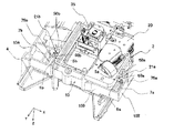
図10及び図11は、Z軸方向マイナス側を上、Y軸方向プラス側を左下にして示す斜視図である。図10は、実施の形態1に係るディスク装置にトラバースユニット2が組み込まれる直前の状態を示し、図11は、ディスク装置にトラバースユニット2が組み込まれた状態を示す。
Next,
10 and 11 are perspective views showing the Z-axis direction minus side as the upper side and the Y-axis direction plus side as the lower left side. FIG. 10 shows a state immediately before the
図10及び図11に示すように、メインシャーシ10において、トラバースシャーシ20のX軸方向外側には、トラバースシャーシ20のボス21a,21bを支持するボス支持部5a,5bがそれぞれ形成されている。ボス支持部5a,5bは、それぞれ、メインシャーシ10の外周壁103からY軸方向に延びた側壁6a,6bを有している。側壁6a,6bは、いずれも、Z軸方向マイナス側を向いた水平端面(XY平面に対して平行な端面)を有している。これら側壁6a,6bのX軸方向外側には、外周壁102,104からX軸方向内側に突出形成されたブロック50a,50bが設けられている。
As shown in FIGS. 10 and 11, in the
図12は、ディスク装置における一方のボス支持部を拡大して示す斜視図であり、Z軸方向マイナス側を上、Y軸方向プラス側を右下にして示すものである。図12に示すように、ボス支持部5aのブロック50aは、メインシャーシ10の外周壁103に対向する鉛直面51と、外周壁102と平行な鉛直面52と、これら鉛直面51,52のZ軸方向プラス側に形成された水平面53とを有している。Z軸方向において、水平面53と側壁6aとの間には、ボス21aの直径よりも僅かに大きい隙間が設けられている。また、ブロック50aは、側壁6aのY軸方向マイナス側に隣接して、外周壁103に対向する鉛直面54を有している。ブロック50aの水平面53及び側壁6aの水平端面により、ボス21aのZ軸方向の位置が規制される。また、ブロック50aの鉛直面54により、ボス21aのY軸方向マイナス側の位置が規制される。これらブロック50aの水平面53及び鉛直面54並びに側壁6aの水平端面に囲まれた部分が、ボス21aを挿入する溝部60aとなる。
FIG. 12 is an enlarged perspective view of one boss support portion in the disk device, showing the Z-axis direction minus side as the upper side and the Y-axis direction plus side as the lower right side. As shown in FIG. 12, the
メインシャーシ10の外周壁103から溝部60aにかけて、長尺部材である弾性爪7aがY軸方向に延びている。この弾性爪7aは、外周壁103に固定された部分を中心として弾性変形可能に構成されている。この弾性爪7aは、ブロック50aの鉛直面54に対向する先端面を有し、この先端面によりボス21aを溝部60a内で保持し、これによりボス21aのY軸方向における位置を規制する。また、弾性爪7aの先端部分には、ボス21aを弾性爪7aに対してZ軸方向に押し当てたときにボス21aに当接する傾斜面71が形成されている。ボス21aを傾斜面71にZ軸方向に押し当てることにより、弾性爪7aが外周壁102側に弾性変形する。
An
なお、弾性爪7aの外周壁102側には、Z軸方向に延びたピン75aが形成されている。ボス21aを傾斜面71に押し当てただけでは弾性爪7aが十分に弾性変形しない場合に、作業者がピン75aを指等で付勢することにより弾性爪7aを弾性変形させることができる。また、弾性爪7aの先端部には、外周壁102側と反対の側に突出する突出部76が形成されている。突出部76は、ボス21aを溝部60aからY軸方向に脱落しにくくするためのものである。
A
なお、図12では図示を省略するが、他方のボス支持部5bは、メインシャーシ10のX軸方向における中心部を中心としてボス支持部5aとぼぼ対称に構成されている。すなわち、図11に示すように、ボス支持部5bは、側壁6b及びブロック50bにより形成される溝60bにボス21bを支持し、弾性爪7bにより位置規制している。これ以外の構成は、図1〜図9を参照して説明したディスク装置と同様である。
In addition, although illustration is abbreviate | omitted in FIG. 12, the other boss |
ボス21a,21bをボス支持部5a,5bに挿入するときには、図10に示すように、ボス21a,21bを弾性爪7a,7bの各傾斜面71(図12)にZ軸方向に押し当て、弾性爪7a,7bを互いに離間する方向に弾性変形させる。ボス21a,21bが側壁6a,6bに当接したところで、ボス21a,21bをY軸方向マイナス側に移動させる。これにより、ボス21a,21bは、弾性爪7a,7bの各突出部76(図12)を乗り越えて移動し、図11に示すように、溝部60a,60b内に挿入される。このように、ボス支持部5a,5bへのボス21a,21bの挿入方向はY軸方向となる。ボス21a,21bが溝部60a,60b内に挿入されると、弾性爪7a,7bは弾性変形前の状態に復帰する。この状態で、ボス21a,21bのY軸方向の位置は、ブロック50a,50bの各鉛直面54(図12)と弾性爪7a,7bの各先端面とによって規制される。また、ボス21a,21bのZ軸方向の位置は、側壁6a,6bの各水平端面とブロック50a,50bの各水平面53(図12)とによって規制される。
When inserting the
ディスク装置が落下等によりZ軸方向の衝撃を受けると、図1〜図9を参照して説明したディスク装置と同様、トラバースユニット2の重量の数十倍に相当する衝撃がボス支持部5a,5bに作用する。しかしながら、この実施の形態1では、ボス21a,21bのボス支持部5a,5bへの挿入方向がY軸方向であり、最も大きな衝撃を受けるZ軸方向ではないため、ボス21a,21bはボス支持部5a,5bから脱落しにくい。言い換えると、ボス21a,21bは、比較的変形しにくいブロック50a,50b及び側壁6a,6bによりZ軸方向に位置規制されているため、ボス支持部5a,5bから脱落しにくい。
When the disk device receives an impact in the Z-axis direction due to dropping or the like, the impact corresponding to several tens of times the weight of the
このように構成されているため、実施の形態1によれば、トラバースユニット2の脱落がより生じにくくなり、耐衝撃性能がさらに向上する。また、ボス21a,21bをボス支持部5a,5bに挿入する際、弾性爪7a,7bに沿ってボス21a,21bを移動させ、溝部60a,60bに挿入できるようにしたので、ボス21a,21bの組み込みが簡単になる。
Since it is configured in this manner, according to the first embodiment , the
実施の形態2.
図13及び図14は、Z軸方向マイナス側を上、Y軸方向プラス側を左下にして示す斜視図である。図13は、実施の形態2に係るディスク装置のトラバースユニット2が組み込まれる直前の状態を示し、図14は、ディスク装置にトラバースユニット2が組み込まれた状態を示す。実施の形態2に係るディスク装置では、メインシャーシ10のボス支持部5a,5bは、実施の形態1と同様に構成されている。すなわち、ボス21a,21bのボス支持部5a,5bへの挿入方向がY軸方向であり、これによりボス21a,21bがボス支持部5a,5bから脱落しにくい構成となっている。これに加えて、この実施の形態2では、トラバースシャーシ20のボス21a,21bの先端部に、図1〜図9を参照して説明したディスク装置と同様の突起22a,22bが形成されている。この突起22a,22bは、ボス支持部5a,5bの側壁6a,6bの外側の面に当接可能に対向する。
13 and 14 are perspective views showing the Z-axis direction minus side as the upper side and the Y-axis direction plus side as the lower left side. 13 shows a state immediately before the
図15は、実施の形態2により得られる効果を模式的に示す概略図であり、Z軸方向マイナス側を上、X軸方向プラス側を右にして示すものである。上述したように、ボス21a,21bの先端に形成された突起22a,22bがボス支持部5a,5bの側壁6a,6bの外側の面に当接可能に対向するため、ディスク装置が落下等による衝撃がボス支持部5a,5bに作用した場合、ボス支持部5a,5bが互いに離間する方向に弾性変形しようとしても、その弾性変形は、突起22a,22bによって抑制される。
FIG. 15 is a schematic diagram schematically showing the effect obtained by the second embodiment , with the Z-axis direction minus side facing up and the X-axis direction plus side facing right. As described above, the
このように、実施の形態2では、実施の形態2の構成に加え、ボス21a,21bの突起22a,22bによりボス支持部5a,5bの互いに離間する方向への弾性変形を抑制するようにしたので、ボス支持部5a,5bからのボス21a,21bの脱落は、ボス21a,21b又はボス支持部5a,5bが破損しない限り、きわめて生じにくくなる。従って、トラバースユニット2の脱落がさらに抑制され、耐衝撃性能がさらに向上する。
As described above, in the second embodiment , in addition to the configuration of the second embodiment, the
実施の形態3.
図16は、Z軸方向マイナス側を上、Y軸方向プラス側を右下にして示すものであり、図17及び図18は、Z軸方向マイナス側を上、Y軸方向プラス側を左下にして示す斜視図である。図16は、実施の形態3に係るディスク装置のトラバースシャーシ20を示す。また、図17は、実施の形態3に係るディスク装置のトラバースユニット2が組み込まれる直前の状態を示し、図18は、ディスク装置にトラバースユニット2が組み込まれた状態を示す。図16及び図17に示すように、実施の形態3に係るトラバースシャーシ20のボス21a,21bは、それぞれの先端部に、実施の形態2で説明した突起22a,22bに加えて、突起25a,25bを有している。突起25aは、突起22aよりもさらにボス21aの先端側に形成されており、突起22aと反対の側に突出している。同様に、突起25bは、突起22bよりもさらにボス21bの先端側に形成されており、突起22bと反対の側に突出している。
Embodiment 3 FIG .
FIG. 16 shows the Z-axis direction minus side up and the Y-axis direction plus side down to the right. FIGS. 17 and 18 show the Z-axis direction minus side up and the Y-axis direction plus side down. FIG. FIG. 16 shows a
図19は、実施の形態3により得られる効果を模式的に示す概略図であり、Z軸方向マイナス側を上、X軸方向プラス側を右にして示すものである。ボス21a,21bをボス支持部5a,5bに挿入すると、ボス21a,21bの突起22a,22bが側壁6a,6bの外側の面に当接可能に対向するのに加えて、ボス21a,21bの突起25a,25bが、ブロック50a,50bに形成された切欠き部55a,55bの内面(X軸方向外側を向いた面)56a,56bに当接可能に対向する。
FIG. 19 is a schematic diagram schematically showing the effect obtained by the third embodiment , with the Z-axis direction minus side facing up and the X-axis direction plus side facing right. When the
このように構成されているため、ディスク装置の落下等による衝撃がボス支持部5a,5bに作用した場合、ボス支持部5a,5bが互いに離間する方向に弾性変形しようとしても、この弾性変形は、ボス21a,21bの突起25a,25bがブロック50a,50bの内面56a,56bに当接することにより抑制される。また、ボス支持部5a,5bの弾性変形は、実施の形態2と同様、ボス21a,21bの突起22a,22bが側壁6a,6bに当接することによっても抑制される。
With this configuration, when an impact due to a drop of the disk device or the like acts on the
このように、実施の形態3では、実施の形態2の構成に加え、ボス21a,21bに形成された突起25a,25bにより、ボス支持部5a,5bの弾性変形がさらに抑制されるため、ボス21a,21bのボス支持部5a,5bからの脱落は、ボス21a,21b又はボス支持部5a,5bが破損しない限り、きわめて生じにくくなる。従って、トラバースユニット2の脱落が一層抑制され、耐衝撃性能が一層向上する。
Thus, in the third embodiment , in addition to the configuration of the second embodiment, the
1 ディスク装置
1a,1b,5a,5b ボス支持部
2 トラバースユニット
4 トレイ
6a,6b,11a,11b 側壁
7a,7b,13a,13b 弾性爪
10 メインシャーシ
12a,12b 溝部
20 トラバースシャーシ
21a,21b ボス
22a,22b 突起
23 カムピン
25a,25b 突起
30 ターンテーブル
35 ピックアップ
50a,50b ブロック
60a,60b 溝部
9 システム
DESCRIPTION OF
Claims (1)
前記ディスク媒体を収容位置と排出位置との間で搬送する搬送手段と、
前記トラバースユニットを、前記収容位置における前記ディスク媒体に対して接近及び離間するよう回動可能に支持するメインシャーシと
を備え、
前記トラバースシャーシは、前記回動のための互いに同軸の一対の回動軸を有し、
前記メインシャーシは、
前記搬送手段による前記ディスク媒体の搬送方向と略平行な方向に開口し、前記一対の回動軸が前記ディスク媒体の前記搬送方向と略平行な方向に挿入される一対の溝部と、
前記ディスク媒体の前記搬送方向と略平行な方向に延在し、前記一対の回動軸を前記一対の溝部から脱落しないように位置規制する弾性変形可能な一対の位置規制部材とを有し、
前記一対の位置規制部材のそれぞれが、前記一対の回動軸を前記一対の溝部に挿入できるよう前記位置規制部材を弾性変形させるために操作されるピンを有していること
を特徴とするディスク装置。 A traverse unit having a turntable that holds and rotates a disk medium, an optical pickup that performs at least one of writing and reading of information to and from the disk medium, and a traverse chassis that supports them.
Transport means for transporting the disk medium between a storage position and a discharge position;
A main chassis that rotatably supports the traverse unit so as to approach and separate from the disk medium at the storage position;
The traverse chassis has a pair of rotation axes coaxial with each other for the rotation,
The main chassis is
A pair of grooves that open in a direction substantially parallel to the transport direction of the disk medium by the transport means, and in which the pair of rotation shafts are inserted in a direction substantially parallel to the transport direction of the disk medium;
A pair of elastically deformable position restricting members extending in a direction substantially parallel to the conveying direction of the disk medium and restricting the position of the pair of rotating shafts so as not to drop out of the pair of groove portions;
Each of the pair of position restricting members has a pin operated to elastically deform the position restricting member so that the pair of rotation shafts can be inserted into the pair of groove portions. apparatus.
Priority Applications (1)
| Application Number | Priority Date | Filing Date | Title |
|---|---|---|---|
| JP2004077345A JP3708106B2 (en) | 2004-03-18 | 2004-03-18 | Disk unit |
Applications Claiming Priority (1)
| Application Number | Priority Date | Filing Date | Title |
|---|---|---|---|
| JP2004077345A JP3708106B2 (en) | 2004-03-18 | 2004-03-18 | Disk unit |
Related Parent Applications (1)
| Application Number | Title | Priority Date | Filing Date |
|---|---|---|---|
| JP2002327701A Division JP3647839B2 (en) | 2002-11-12 | 2002-11-12 | Disk unit |
Publications (3)
| Publication Number | Publication Date |
|---|---|
| JP2004206875A JP2004206875A (en) | 2004-07-22 |
| JP2004206875A5 JP2004206875A5 (en) | 2005-07-07 |
| JP3708106B2 true JP3708106B2 (en) | 2005-10-19 |
Family
ID=32822293
Family Applications (1)
| Application Number | Title | Priority Date | Filing Date |
|---|---|---|---|
| JP2004077345A Expired - Fee Related JP3708106B2 (en) | 2004-03-18 | 2004-03-18 | Disk unit |
Country Status (1)
| Country | Link |
|---|---|
| JP (1) | JP3708106B2 (en) |
-
2004
- 2004-03-18 JP JP2004077345A patent/JP3708106B2/en not_active Expired - Fee Related
Also Published As
| Publication number | Publication date |
|---|---|
| JP2004206875A (en) | 2004-07-22 |
Similar Documents
| Publication | Publication Date | Title |
|---|---|---|
| CN101308664A (en) | Disk device | |
| US6426935B1 (en) | Supporting structure of floating chassis of disc apparatus | |
| JP3647839B2 (en) | Disk unit | |
| US8281330B2 (en) | Disk apparatus | |
| JP3708106B2 (en) | Disk unit | |
| JP2004164721A5 (en) | ||
| US7281254B2 (en) | Optical disc drive having a traverse holder that is rotatable around an axis that is mutually different from the axis of a traverse base | |
| JP2004206875A5 (en) | ||
| EP1788557A2 (en) | Hard disk drive and method of fabricating the same | |
| US6256174B1 (en) | Disk drive apparatus with a high positional precision magnetic head | |
| JP4234634B2 (en) | Magnetic disk unit | |
| JP4185844B2 (en) | Optical disk device | |
| WO2020144819A1 (en) | Optical disk device | |
| JP2005018853A (en) | Optical disk device | |
| JPH0845207A (en) | Magnetic head for disk device | |
| JP2002197824A (en) | Adaptor for optical disk | |
| JP2008059721A (en) | Optical disk reproducing apparatus | |
| JP2003123375A (en) | Disk rotating mechanism and disk device using the same | |
| JP2008159208A (en) | Magnetic disk device | |
| JPH11273312A (en) | Disk drive | |
| JPH11273275A (en) | Disk drive device | |
| JPH11273271A (en) | Disk drive device | |
| JPH11273282A (en) | Disk drive device | |
| JPH11273272A (en) | Disk drive device | |
| JPH11273334A (en) | Disk drive and disk cartridge |
Legal Events
| Date | Code | Title | Description |
|---|---|---|---|
| A521 | Written amendment |
Free format text: JAPANESE INTERMEDIATE CODE: A523 Effective date: 20041227 |
|
| TRDD | Decision of grant or rejection written | ||
| A01 | Written decision to grant a patent or to grant a registration (utility model) |
Free format text: JAPANESE INTERMEDIATE CODE: A01 Effective date: 20050802 |
|
| A61 | First payment of annual fees (during grant procedure) |
Free format text: JAPANESE INTERMEDIATE CODE: A61 Effective date: 20050802 |
|
| R150 | Certificate of patent or registration of utility model |
Free format text: JAPANESE INTERMEDIATE CODE: R150 Ref document number: 3708106 Country of ref document: JP Free format text: JAPANESE INTERMEDIATE CODE: R150 |
|
| FPAY | Renewal fee payment (event date is renewal date of database) |
Free format text: PAYMENT UNTIL: 20080812 Year of fee payment: 3 |
|
| FPAY | Renewal fee payment (event date is renewal date of database) |
Free format text: PAYMENT UNTIL: 20090812 Year of fee payment: 4 |
|
| FPAY | Renewal fee payment (event date is renewal date of database) |
Free format text: PAYMENT UNTIL: 20090812 Year of fee payment: 4 |
|
| FPAY | Renewal fee payment (event date is renewal date of database) |
Free format text: PAYMENT UNTIL: 20100812 Year of fee payment: 5 |
|
| FPAY | Renewal fee payment (event date is renewal date of database) |
Free format text: PAYMENT UNTIL: 20110812 Year of fee payment: 6 |
|
| FPAY | Renewal fee payment (event date is renewal date of database) |
Free format text: PAYMENT UNTIL: 20110812 Year of fee payment: 6 |
|
| FPAY | Renewal fee payment (event date is renewal date of database) |
Free format text: PAYMENT UNTIL: 20120812 Year of fee payment: 7 |
|
| FPAY | Renewal fee payment (event date is renewal date of database) |
Free format text: PAYMENT UNTIL: 20120812 Year of fee payment: 7 |
|
| FPAY | Renewal fee payment (event date is renewal date of database) |
Free format text: PAYMENT UNTIL: 20130812 Year of fee payment: 8 |
|
| R250 | Receipt of annual fees |
Free format text: JAPANESE INTERMEDIATE CODE: R250 |
|
| R250 | Receipt of annual fees |
Free format text: JAPANESE INTERMEDIATE CODE: R250 |
|
| R250 | Receipt of annual fees |
Free format text: JAPANESE INTERMEDIATE CODE: R250 |
|
| R250 | Receipt of annual fees |
Free format text: JAPANESE INTERMEDIATE CODE: R250 |
|
| R250 | Receipt of annual fees |
Free format text: JAPANESE INTERMEDIATE CODE: R250 |
|
| LAPS | Cancellation because of no payment of annual fees |