JP3702139B2 - Cooking equipment - Google Patents
Cooking equipment Download PDFInfo
- Publication number
- JP3702139B2 JP3702139B2 JP2000015152A JP2000015152A JP3702139B2 JP 3702139 B2 JP3702139 B2 JP 3702139B2 JP 2000015152 A JP2000015152 A JP 2000015152A JP 2000015152 A JP2000015152 A JP 2000015152A JP 3702139 B2 JP3702139 B2 JP 3702139B2
- Authority
- JP
- Japan
- Prior art keywords
- cooking
- unit
- cooking unit
- container
- station
- Prior art date
- Legal status (The legal status is an assumption and is not a legal conclusion. Google has not performed a legal analysis and makes no representation as to the accuracy of the status listed.)
- Expired - Lifetime
Links
Images


Description
【0001】
【発明の属する技術分野】
本発明は、油脂及び澱粉質を含有するルウ等を製造するための加熱調理装置、さらに詳しくは加熱量を高精度に制御して効率的に所望の加熱調理を行うことができる加熱調理装置に関する。
【0002】
【従来の技術】
例えば小麦粉と油脂及び調味料を主原料とし、これらを加熱・混練してつくるカレー、シチュー、ホワイトソース等のルウは、小麦粉と油脂が融合した独得の色とテクスチャーを有している。また、ルウ中の調味料がこくと潤いの有る風味と香りを醸し出し、ルウは食品基材として、あるいは料理に色どりや風味を添える為のものとして広く使用されている。
一般に、ルウ特有の色、風味や香りは、ルウを製造する際の加熱条件によって大きく左右されることが知られている。そして、特に風味や香りの豊かなルウを得るためには、ルウを高温でしかも均一に加熱することが必要であるとされている。さらに、所定加熱後は、ルウの風味保持、色調の劣化防止、充填等の作業の効率化を実現するために、均一に所定温度まで冷却し、温度管理することが望ましい。
特許第2584669号公報は、油脂及び澱粉質材料を含有する原料を、焙煎釜により品温が75℃〜200℃で5分から90分間加熱処理した後、二軸エクストルーダーにより該加熱処理終了後5分以内に原料の品温が70℃以下になるまで冷却する方法を開示している。
しかしながら、特許第2584669号公報に記載のルウの製造方法においては、温度管理の精度、特に、前記エクストルーダーでは焙煎釜により加熱処理した原料を少量ずつ冷却することから、加熱処理後直ぐに冷却された原料と加熱処理後暫くしてから冷却された原料とで加熱量が異なってくるおそれがあるという問題が完全に解決されていない。また、この方法においては、二軸エクストルーダにより処理した原料を次の工程に送る前に一時的に貯蔵しようとする場合に、別途ストックタンクを設ける必要がある。したがって、この場合、特に合成乳化剤を使用しないでルウ等を製造しようとしたときにストックタンク内において原料が分離をおこすおそれがある。
【0003】
【発明が解決しようとする課題】
本発明は、上述した問題点に鑑みてなされたものであって、ルウ等の調理材料を均一かつ充分に加熱し、かつ均一に所定温度まで冷却、高精度に温度管理することができ、焙煎特性を充分に生かして風味、香りにおいてコクのあるルウ等を製造することができる加熱調理装置を提供することを目的とする。
本発明はまた、冷却後の調理材料のストックタンクとして兼用でき、しかも調理材料を1バッチ毎にストックすることにより、その中で調理材料の分離が生じても正確な配合割合が保たれ、必要時に攪拌装置で攪拌することにより均一な混合状態を再現でき、特に合成乳化剤を使用しない場合に生じやすい原料分離の問題を有効に解決できる加熱調理装置を提供することを目的とする。
【0004】
【課題を解決するための手段】
本発明は、底面にジャケットを有する加熱用容器と、前記加熱用容器内の調理材料を攪拌するための攪拌装置とを有する第1調理部と、底面にジャケットを有する冷却用容器と、前記冷却用容器内の調理材料を攪拌するための攪拌装置とを有する第2調理部とを備え、前記第1調理部の下流側に、前記第1調理部から供給される調理材料を前記第2調理部に受取るための受取ステーションと、前記第2調理部に受取った調理材料を排出するための排出ステーションとを設け、前記第2調理部は、前記各ステーションの間を移動可能に配置され、前記各ステーションは、前記第2調理部の前記ジャケットに冷却媒体または加熱媒体を供給するための冷却媒体または加熱媒体の供給部を備え、前記第1調理部と前記受取ステーションとの間に、調理材料の供給パイプを備え、かつ該供給パイプが冷却ジャケットを有することを特徴とする加熱調理装置である。
【0005】
このような構成によれば、第1調理部において調理材料を攪拌しながら均一かつ充分に加熱し、加熱後の調理材料を受取ステーションの第2調理部に供給して、均一に所定温度まで冷却することができる。しかも当該第2調理部を冷却後の調理材料のストックタンクとして兼用でき、その中で調理材料を1バッチ毎にストックすることにより、調理材料の分離が生じても正確な配合割合が保たれ、必要時に攪拌装置で攪拌することにより均一な混合状態を再現でき、特に合成乳化剤を使用しない場合に生じやすい原料分離の問題を有効に解決できる。また、冷却後の調理材料を第2調理部ごと排出ステーションに移動させて、別の第2調理部を受取ステーションに配置することにより、製品の連続生産が可能となり、しかも排出ステーションには第2調理部のジャケットへの冷却媒体または加熱媒体の供給部が備わっているので、排出ステーションにおいて冷却後の調理材料を高精度に温度管理することができる。また、冷却後の調理材料を第2調理部ごと排出ステーションに移動させるので、その間、調理材料を移送するためのパイプが必要なく、パイプ内で調理材料の残留が生じるという問題がなく、正確な配合割合を保つことができる。さらに、できるだけ加熱を避けたい調理原料を第2調理部において投入して混合することにより、従来より調理原料毎の加熱量に変化を持たせてより風味の・香りのよい製品を得ることができる。また、前記第1調理部と前記受取ステーションとの間に、調理材料の供給パイプを備え、かつ該供給パイプが冷却ジャケットを有しているので、特に調理材料が固形脂等の冷却により固化する原料を含む場合に、調理材料を排出、供給した後、供給パイプの冷却ジャケットに冷却媒体を導入することにより、供給パイプ内に残留する調理材料を固化させて調理材料の液垂れを防止することができる。したがって、この場合には、受取ステーションにおいて第2調理部の移動後に調理材料が液垂れをすることがないので、衛生上の観点から受取ステーションを頻繁に洗浄等する必要がなく作業効率の低下を防止できる。
【0006】
本発明の他の好ましい態様によれば、前記第1調理部の下流側に、さらに前記第2調理部に受取った調理材料の待機ステーションを設け、前記第2調理部は、前記各ステーションの間を移動可能に配置され、前記各ステーションは、前記第2調理部の前記ジャケットに冷却媒体または加熱媒体を供給するための冷却媒体または加熱媒体の供給部を備えている。このような構成によれば、冷却後の調理材料を収容した第2調理部を排出ステーションに移動させる前に、待機ステーションにおいて高精度に温度管理しながら待機させておくことができ、製品をより大量に連続生産することが可能となる。本発明の他の好ましい態様によれば、前記第2調理部を2以上備えている。このような構成によれば、上述のように、冷却後の調理材料を収容した第2調理部を排出ステーションに移動させて、別の第2調理部を受取ステーションに配置することにより、製品の連続生産が可能となる。本発明の他の好ましい態様によれば、前記第1調理部の略真下方向に、前記受取ステーションが配置されるように構成されている。このような構成によれば、第1調理部と受取ステーションの第2調理部との距離を可及的に短くすることができ、しかも加熱後の調理材料を重力に従って第2調理部に無理なく効率的に排出、供給することができる。本発明の他の好ましい態様によれば、前記加熱用容器から調理材料を排出して前記受取ステーションに供給するための加圧エアー供給装置を有している。このような構成によれば、上述の第1調理部の略真下方向に受取ステーションが配置される構成と相まって、加熱後の調理材料を第2調理部にさらに効率的に排出、供給することができる。さらに、本発明の他の好ましい態様によれば、前記供給パイプの冷却ジャケットに導入する冷却媒体の温度が20〜40℃である。これにより、調理材料の液垂れを防止し、かつ前記供給パイプに結露が生じることを防止することができる。
【0007】
【発明の実施の形態】
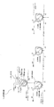
以下に、本発明の実施形態を図に基づいて説明する。実施態様のカレールウ製造用の加熱調理装置10は、図1に示すように、例えば1台の第1調理部14、及び第1調理部14の下流側に配置された例えば3台の第2調理部16からなる。
【0008】
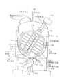
第1調理部14は、図2に示すように、架台110に支持された半球形の容器112に、回転軸線Aが垂直線に対し25ないし40°、好ましくは30°傾斜した回転軸114に内側攪拌羽根116及び外側攪拌羽根118が配置されている。容器112は、内面を半球状にした底部22の外面に蒸気及び35℃の冷却水を選択的に供給する温度制御パイプ115が取り付けられ、さらにドレインパイプ119が連結されたジャケット構造となっている。
【0009】
容器112の上端部は蓋部材120によって開放自在に閉塞され、蓋部材120には調理材料投入口122及び回転軸114が取り付けられている。回転軸114の上端には攪拌羽根の駆動源となる反転変速機能付きのモータ130が取り付けられ、従って内側攪拌羽根116及び外側攪拌羽根118は同一方向にも反対方向にも回転駆動され、しかもその回転速度も任意に選択制御可能である。内側攪拌羽根116の回転速度は20ないし150rpmの範囲であり、外側攪拌羽根118の回転速度は10ないし50rpmの範囲である。内側攪拌羽根116及び外側攪拌羽根118の下端部は、軸支部材132によって回転軸線Aを中心に回転可能に支持されている。
【0010】
内側攪拌羽根116は、回転軸線Aからの距離が異なるようにアーム134,135によって支持された攪拌軸136,137を有し、攪拌軸136,137には回転軸線Aに関し対称でなく配設された複数の攪拌棒140が取り付けられている。攪拌棒140は回転軸線Aに対し直交する方向に延びており、攪拌棒140の少なくともあるものは外側攪拌羽根118の近傍まで延びた長さを有する。内側攪拌羽根116の回転軸線Aを含む平面の断面は、図2に示すような矩形に限らず、楕円形や円形であってもよく、また回転軸線Aを中心とする楕円形であってもよい。
【0011】
外側攪拌羽根118は環状であって、周囲に容器112の内面に接触して調理材料Mを掻き取る合成樹脂製の掻取羽根150が取り付けられている。掻取羽根150は、回転軸線Aの両側の掻取羽根150が容器112の同一の領域を掻き取ることがないように回転軸線Aに関し非対称に配置される。外側攪拌羽根118の回転軸線Aを含む平面の断面は、図2に示すような円形に限らず、楕円形であってもよい。また、外側攪拌羽根118には、内側攪拌羽根116近傍まで延びる得る攪拌棒を取り付けてもよい。
内側攪拌羽根116には、回転軸線Aの近くに容器112の下方部に当たる位置に、回転軸線Aから若干ずらして設けられた温度センサー取り付け部材170を介して温度センサー172が取り付けられ、攪拌中の調理材料の温度を測定する。
蓋部材120にはまた、容器112から調理材料を排出させるための加圧エア供給パイプ190が連結されている。容器112の底部には、調理材料Mを排出するための弁受体180、及び空圧シリンダー182によって制御される弁部材184が配置され、弁受体180に供給パイプ186が連結されている。
【0012】
第2調理部16には、釜すなわち容器20と攪拌装置21とを有する。
容器20は、図3及び図4に示すように、内面を半球状にした底部22の外面にジャケット構造が形成されている。容器20は、このジャケット構造内に、冷却水、又は加熱水を導入することによって、容器20内に投入された調理材料を、冷却又は加熱できるように構成されている。容器20の上方開口部には、蓋部28が配置され、蓋部28には調理材料を投入するための調理材料投入口25及び容器20から調理材料を排出させるための加圧エア供給パイプ29が連結されている。
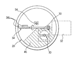
蓋部28にはさらに、底部22の内面の半球状の中心Oを通過する傾斜した回転軸30が取り付けられ、回転軸30はモータ32によって5ないし40rpmで回転させられる。回転軸30の先端には、底部22の内面に沿って円弧状に延びた攪拌羽根34が取り付けられている。攪拌羽根34の外側すなわち底部22の内面側に、合成樹脂製の掻き取り羽根36が断続的に取り付けられている。掻き取り羽根36R、36Lは左右非対称であり、一方の側の掻き取り羽根36Rによって掻き取られなった部分を他方の掻き取り羽根36Lが掻き取るようになっている。
【0013】
容器20内の攪拌羽根34及び掻き取り羽根36によって調理材料Mが掻き上げられる領域すなわち図2における回転軸30の下側の領域には、パドル型攪拌羽根40が配置されている。パドル型攪拌羽根40は、パドル用モータ60によって正逆回転可能な垂直軸62の先端に取り付けられ、図4に示す第1斜線で示す領域46に配置されることによって、調理材料Mの塊を高い効率で粉砕し及び攪拌を行うことができる。パドル型攪拌羽根40は、図5の(A)、(B)に示すように、外形が全体的に回転軸Rを中心とする対称形外形の平面状矩形であり、内部に調理材料Mの抵抗を低め攪拌能力を高めるために複数の非対称形の貫通孔142が設けられている。
【0014】
容器20内には、底部内面の半球状の中心0から若干ずらして回転軸30と干渉しない位置に温度センサー52を先端部に取り付けた垂直支持棒54が挿入されている。垂直支持棒54の先端部に取り付けられた温度センサー52は、調理材料Mの中心付近に当たる領域に配置されることによって、温度を高精度に測定することができる。
容器20の底部には、調理材料Mを排出するための弁受体60、及び空圧シリンダー62によって制御される弁部材64が配置され、弁受体60に供給パイプ66が連結されている。なお、容器20内の掻き取り羽根36によって調理材料Mが掻き下げられる領域すなわち図4における回転軸30の上側の領域に邪魔板を配置して、パドル型攪拌羽根40によって破壊された調理材料Mの塊を効率的に衝突させて効率よく攪拌するようにすることもできる。この場合、邪魔板は前記垂直支持棒54に取り付ければよい。
【0015】
3台の第2調理部16は、搬送装置(図示せず)によって移動可能に配置され、第1調理部14から調理材料Mを供給される受取ステーション200、調理材料Mを一時的に貯蔵するための待機ステーション202、及び調理材料Mを図示しないストレーナーすなわち脱泡装置を介して充填装置に連通する排出ステーション204の間で搬送される。前記各ステーションは、第2調理部16のジャケットに冷却媒体または加熱媒体を供給するための冷却媒体または加熱媒体の供給部を備え、搬送されてきた第2調理部16と接続されるように構成されている。具体的には、受取ステーション200においては温度制御パイプ224から7℃の冷却水及び62℃の加熱水が選択的に供給され、待機ステーション202においては温度制御パイプ24から62℃の加熱水が供給され、また排出ステーション204においては温度制御パイプ24から62℃の加熱水が供給されるように構成されている。また、前記各ステーションは、第2調理部16のモータ32及びパドル用モータ60に電力を供給するための電力供給部を有し、搬送されてきた第2調理部16と接続されるように構成されている。
本実施形態において、受取ステーション200は、第1調理部14の略真下方向に配置され、第1調理部14と受取ステーション200の間には、加熱調理済の調理材料Mを第2調理部12に供給するための供給パイプを備え、この供給パイプの外面ににはジャケット構造が形成されており、35℃の冷却水が導入されるように構成されている(図示せず)。
【0016】
次に、上述した構成の加熱調理装置10の作動について説明する。
第1調理部14において、内側攪拌羽根116を30rpm及び外側攪拌羽根118を15rpmで同一方向に回転させながら、前置調理部(図示せず)で予め小麦粉と油脂とを加熱調理して得た小麦粉ルウ、粉体、ペースト、油脂を加える。さらに、温度センサー172によって温度制御しながら温度制御パイプ115に水蒸気を供給して加熱調理する。
続いて、調理材料の品温が90℃に達した時点で、内側攪拌羽根116を外側攪拌118と反対方向に15rpmで回転させながら加熱調理する。これにより、小麦粉等の澱粉質原料と油脂とを含む調理材料にペースト(特に水分を多く含むもの)を加えた場合に品温上昇に伴って物性が急激に硬化するという特有の現象に好適に対応し、調理材料を高い効率で粉砕し及び攪拌を行うことができる。
【0017】
第1調理部14において調理材料の所定の加熱調理が終了すると、温度制御パイプ115に水蒸気に換えて35℃の冷却水を供給して調理材料を予備冷却する。これにより、調理材料を軟化させて容器112内の加熱調理済の調理材料を第2調理部16へ供給しやすくなる。
また、加熱調理済の調理材料が軟化してきたら内側攪拌羽根116を再び外側攪拌118と同一方向に回転させる。これにより、調理材料を攪拌する際に生じる回転軸114に対する負荷を可及的に抑え、効率よく攪拌を行うことができる。続いて、エアーシリンダー182を作動させて弁受体180から弁部材184を分離させ、また容器112に加圧エア供給パイプ190から加圧エアを供給して、供給パイプを介して、容器112内の加熱調理済の調理材料を受取ステーション200の第2調理部16に供給する。また、容器112内の調理材料の供給終了後、上記供給パイプのジャケット構造に35℃の冷却水を導入し、供給パイプ内に残留する調理材料を固化させて、調理材料の液垂れを防止する。
【0018】
受取ステーション200の第2調理部16においては、容器20のジャケット構造に温度制御パイプ224から7℃の冷却水を入れ、温度センサー52によって温度管理しながら加熱調理済の調理材料を冷却すると同時に、回転軸30すなわち攪拌羽根34をモータ32によって15rpmで回転させ、パドル用モータ60によってパドル型攪拌羽根40を100rpmで回転させて調理材料を均一に混合しまた調理材料の塊を粉砕しながら62℃まで冷却する。調理材料が62℃まで冷却されたら、温度制御パイプ224に7℃の冷却水に換えて62℃の加熱水を供給して調理材料の品温を62℃に保持する。その後、第2調理部16を待機ステーション202に移動させて、調理材料を攪拌し、62℃に保持しながら貯蔵して排出を待ち、排出時に、排出ステーション204に移動させて、エアーシリンダー62を作動させて弁受体60から弁部材64を分離させ、また容器20に加圧エア供給パイプ29から加圧エアを供給して、容器20内の調理材料を排出し、ストレーナーすなわち脱泡装置を介して充填装置へ供給する。
【0019】
このように、第2調理部16は、排出を待つ間に調理材料を貯蔵しておくことができる。また、仮にこの貯蔵中の調理材料が分離を生じても攪拌羽根34及びパドル型攪拌羽根40を回転させることにより均一な混合状態を再現することができる。したがって、貯蔵中の調理材料の分離を心配する必要がないため合成乳化剤を使用しないで焙煎特性を充分に生かして風味、香りにおいてコクのあるルウ等を製造することができる。また、待機ステーション202及び排出ステーション204においても第2調理部16に62℃の加熱水を供給することができるため、調理材料を高精度に温度管理することができる。さらに、第2調理部16では、例えば乳原料、野菜や果実の液汁等の加熱を避けたい原料を第1調理部14に投入せずに非加熱調理材料として投入することができ、原料の新鮮な生の風味を活かしたルウ等を製造することもできる。
なお、本発明の加熱調理装置は、上記実施形態の装置に限定されるものでなく、例えば、第2調理部において冷却用容器と攪拌装置を一体に構成するのではなく、各ステーションに攪拌装置を設け、冷却用容器のみを移動可能に配置し、各ステーションにおいて冷却用容器と攪拌装置とが組み合わさって第2調理部を形成するように構成することもでき、この他にも種々の態様を包含し得る。
【図面の簡単な説明】
【図1】本発明の加熱調理装置の実施形態の構成説明図である。
【図2】本発明の実施形態の第1調理部の垂直断面図である。
【図3】本発明の実施形態の第2調理部の垂直断面図である。
【図4】図2に示す第2調理部の水平断面図である。
【図5】本発明の他の実施形態の攪拌羽根の正面図である。
【符号の説明】
M 調理材料
10 加熱調理装置
14 第1調理部
16 第2調理部
20 容器
21 攪拌装置
22 底部
28 蓋部
29 加圧エア供給パイプ
30 回転軸
34 攪拌羽根
36 掻き取り羽根
40 パドル型攪拌羽根
112 容器
114 回転軸
115 温度制御パイプ
116 内側攪拌羽根
118 外側攪拌羽根
140 攪拌棒
150 攪拌羽根
200 受取ステーション
202 待機ステーション
204 排出ステーション
224 温度制御パイプ
227 ドレインパイプ
234 温度制御パイプ
237 ドレインパイプ
244 温度制御パイプ
247 ドレインパイプ[0001]
BACKGROUND OF THE INVENTION
The present invention relates to a cooking device for producing roux or the like containing fat and starch, and more particularly to a cooking device capable of efficiently performing desired cooking by controlling the amount of heating with high accuracy. .
[0002]
[Prior art]
For example, roux such as curry, stew, white sauce, etc. made by heating and kneading these flours, fats and fats and seasonings, has a unique color and texture in which flour and fats are fused. In addition, the seasoning in the roux brings out a rich and moist flavor and aroma, and the roux is widely used as a food base or for adding color and flavor to dishes.
In general, it is known that the color, flavor, and fragrance unique to luu are greatly affected by the heating conditions when producing roux. In order to obtain a roux that is particularly rich in flavor and aroma, it is necessary to heat the roux at a high temperature and uniformly. Furthermore, after predetermined heating, it is desirable to uniformly cool the temperature to a predetermined temperature and manage the temperature in order to realize the efficiency of operations such as maintaining the flavor of the roux, preventing the deterioration of the color tone, and filling.
In Japanese Patent No. 2584669, a raw material containing fats and oils and starchy material is heated in a roasting pot at a temperature of 75 ° C. to 200 ° C. for 5 minutes to 90 minutes, and then the heat treatment is completed by a biaxial extruder. It discloses a method of cooling until the product temperature of the raw material becomes 70 ° C. or less within 5 minutes.
However, in the method for producing roux described in Japanese Patent No. 2584669, the accuracy of temperature control, in particular, in the extruder, the raw material heated by the roasting pot is cooled little by little, so that it is cooled immediately after the heat treatment. The problem that the amount of heating may differ between the raw material and the raw material cooled after a while after the heat treatment has not been completely solved. Moreover, in this method, when it is going to store temporarily the raw material processed with the biaxial extruder before sending to the following process, it is necessary to provide a separate stock tank. Therefore, in this case, there is a possibility that the raw material may be separated in the stock tank particularly when trying to produce roux or the like without using a synthetic emulsifier.
[0003]
[Problems to be solved by the invention]
The present invention has been made in view of the above-described problems, and is capable of heating cooking ingredients such as roux uniformly and sufficiently, uniformly cooling to a predetermined temperature, and controlling the temperature with high accuracy. It is an object of the present invention to provide a cooking device capable of producing roux having a rich flavor and aroma by making full use of roast characteristics.
The present invention can also be used as a stock tank for cooking ingredients after cooling. Further, by storing the cooking ingredients in batches, an accurate blending ratio can be maintained even if separation of the cooking ingredients occurs. An object of the present invention is to provide a cooking device that can reproduce a uniform mixed state sometimes by stirring with a stirrer, and can effectively solve the problem of separation of raw materials that is likely to occur particularly when a synthetic emulsifier is not used.
[0004]
[Means for Solving the Problems]
The present invention includes a heating container having a jacket on the bottom, a first cooking unit having a stirring device for stirring the cooking material in the heating container, a cooling container having a jacket on the bottom, and the cooling A second cooking unit having a stirring device for stirring the cooking material in the container for cooking, the cooking material supplied from the first cooking unit on the downstream side of the first cooking unit A receiving station for receiving the cooking material and a discharging station for discharging the cooking material received by the second cooking unit, wherein the second cooking unit is arranged to be movable between the stations, each station is provided with a supply of cooling or heating medium for supplying a coolant or heating medium to the jacket of the second cooking unit, between said receiving station and said first cooking part, tone Comprising a feed pipe of material, and a heating cooking apparatus in which the supply pipe and having a cooling jacket.
[0005]
According to such a configuration, the cooking material is uniformly and sufficiently heated in the first cooking unit while stirring, and the heated cooking material is supplied to the second cooking unit of the receiving station and uniformly cooled to a predetermined temperature. can do. In addition, the second cooking unit can be used as a stock tank for cooking materials after cooling, and by storing the cooking materials in batches, the correct blending ratio is maintained even if separation of the cooking materials occurs. By stirring with a stirrer when necessary, a uniform mixed state can be reproduced, and the problem of separation of raw materials that is likely to occur when a synthetic emulsifier is not used can be effectively solved. Further, by moving the cooled cooking material together with the second cooking unit to the discharge station and arranging another second cooking unit at the receiving station, continuous production of the product becomes possible. Since the cooling medium or the heating medium supply unit to the jacket of the cooking unit is provided, the temperature of the cooking material after cooling can be accurately controlled at the discharge station. Moreover, since the cooking material after cooling is moved to the discharge station together with the second cooking unit, there is no need for a pipe for transferring the cooking material, and there is no problem that the cooking material remains in the pipe. The blending ratio can be maintained. Furthermore, by adding and mixing the cooking ingredients that are desired to avoid heating as much as possible in the second cooking section, it is possible to obtain a more flavorful and fragrant product by changing the heating amount for each cooking ingredient than before. . In addition, a cooking material supply pipe is provided between the first cooking unit and the receiving station, and the supply pipe has a cooling jacket, so that the cooking material is solidified by cooling solid fat or the like. When the ingredients are included, after the cooking material is discharged and supplied, a cooling medium is introduced into the cooling jacket of the supply pipe to solidify the cooking material remaining in the supply pipe and prevent the cooking material from dripping. Can do. Therefore, in this case, since the cooking material does not drip after the movement of the second cooking unit at the receiving station, there is no need to frequently wash the receiving station from the viewpoint of hygiene and the work efficiency is reduced. Can be prevented.
[0006]
According to another preferred aspect of the present invention, a standby station for the cooking material received by the second cooking unit is further provided on the downstream side of the first cooking unit, and the second cooking unit is provided between the stations. Each station includes a cooling medium or heating medium supply unit for supplying a cooling medium or a heating medium to the jacket of the second cooking unit. According to such a structure, before moving the 2nd cooking part which accommodated the cooking material after cooling to a discharge | emission station, it can be made to wait with high-precision temperature control in a standby station, and a product can be made more Large-scale continuous production is possible. According to another preferred aspect of the present invention, two or more second cooking units are provided. According to such a configuration, as described above, the second cooking unit containing the cooking material after cooling is moved to the discharge station, and another second cooking unit is arranged at the receiving station. Continuous production is possible. According to another preferred aspect of the present invention, the receiving station is arranged substantially directly below the first cooking unit. According to such a configuration, the distance between the first cooking unit and the second cooking unit of the receiving station can be shortened as much as possible, and the heated cooking material can be easily fed to the second cooking unit according to gravity. Efficient discharge and supply. According to another preferred aspect of the present invention, the apparatus has a pressurized air supply device for discharging the cooking material from the heating container and supplying it to the receiving station. According to such a configuration, coupled with the configuration in which the receiving station is disposed substantially directly below the first cooking unit, the heated cooking material can be discharged and supplied to the second cooking unit more efficiently. I can . Et al is, according to another preferred embodiment of the present invention, the temperature of the cooling medium introduced into the cooling jacket of the supply pipe is 20 to 40 ° C.. Thereby, dripping of a cooking material can be prevented and it can prevent that dew condensation arises in the said supply pipe.
[0007]
DETAILED DESCRIPTION OF THE INVENTION
Embodiments of the present invention will be described below with reference to the drawings. As shown in FIG. 1, the heating cooking apparatus 10 for manufacturing a carousel according to the embodiment includes, for example, one first cooking unit 14 and, for example, three second cooking units arranged on the downstream side of the first cooking unit 14. Part 16.
[0008]
As shown in FIG. 2, the first cooking unit 14 has a
[0009]
The upper end portion of the
[0010]
The inner stirring blade 116 has stirring
[0011]
The outer stirring blade 118 has an annular shape, and a synthetic
A
The lid member 120 is also connected to a pressurized
[0012]
The second cooking unit 16 includes a pot, that is, a
As shown in FIGS. 3 and 4, the
Further, an inclined rotating
[0013]
A paddle
[0014]
A
A
[0015]
The three second cooking units 16 are movably arranged by a transport device (not shown), and receive the cooking material M from the first cooking unit 14 and temporarily store the cooking material M. The waiting station 202 for the transfer and the cooking material M are transported between a discharge station 204 communicating with the filling device via a strainer or defoaming device (not shown). Each station includes a cooling medium or heating medium supply unit for supplying a cooling medium or a heating medium to the jacket of the second cooking unit 16, and is configured to be connected to the second cooking unit 16 that has been conveyed. Has been. Specifically, the receiving station 200 is selectively supplied with 7 ° C. cooling water and 62 ° C. heating water from the temperature control pipe 224, and the standby station 202 is supplied with 62 ° C. heating water from the
In the present embodiment, the receiving station 200 is disposed substantially directly below the first cooking unit 14, and the cooked cooking material M is placed between the first cooking unit 14 and the receiving station 200 in the
[0016]
Next, the operation of the cooking device 10 having the above-described configuration will be described.
In the 1st cooking part 14, while rotating the inner stirring blade 116 and the outer stirring blade 118 in the same direction at 15 rpm, the pre-cooking part (not shown) preliminarily cooked flour and fats and oils. Add flour roux, powder, paste, fat. Further, steam is supplied to the
Subsequently, when the product temperature of the cooking material reaches 90 ° C., cooking is performed while rotating the inner stirring blade 116 at 15 rpm in the opposite direction to the outer stirring 118. This makes it suitable for the specific phenomenon that the physical properties harden rapidly as the product temperature rises when a paste (especially containing a lot of water) is added to a cooking material containing starchy raw materials such as wheat flour and fats and oils. Correspondingly, the cooking ingredients can be crushed and stirred with high efficiency.
[0017]
When the predetermined cooking of the cooking material is completed in the first cooking unit 14, 35 ° C. cooling water is supplied to the
Further, when the cooked cooking material is softened, the inner stirring blade 116 is again rotated in the same direction as the outer stirring 118. Thereby, the load with respect to the rotating shaft 114 produced when stirring a cooking material is suppressed as much as possible, and stirring can be performed efficiently. Subsequently, the
[0018]
In the second cooking section 16 of the receiving station 200, cooling water of 7 ° C. is put into the jacket structure of the
[0019]
Thus, the 2nd cooking part 16 can store a cooking material, waiting for discharge | emission. Even if the cooking material being stored is separated, a uniform mixed state can be reproduced by rotating the stirring
In addition, the heating cooking apparatus of this invention is not limited to the apparatus of the said embodiment, For example, in the 2nd cooking part, the container for cooling and the stirring apparatus are not comprised integrally, but a stirring apparatus is provided in each station. It is also possible to dispose only the cooling container so that the second cooking unit is formed by combining the cooling container and the stirrer at each station. Can be included.
[Brief description of the drawings]
FIG. 1 is a configuration explanatory diagram of an embodiment of a cooking device according to the present invention.
FIG. 2 is a vertical sectional view of a first cooking unit according to an embodiment of the present invention.
FIG. 3 is a vertical sectional view of a second cooking unit according to the embodiment of the present invention.
4 is a horizontal sectional view of a second cooking unit shown in FIG. 2. FIG.
FIG. 5 is a front view of a stirring blade according to another embodiment of the present invention.
[Explanation of symbols]
M Cooking material 10 Heat cooking device 14 First cooking unit 16
Claims (5)
底面にジャケットを有する冷却用容器と、前記冷却用容器内の調理材料を攪拌するための攪拌装置とを有する第2調理部とを備え、
前記第1調理部の下流側に、前記第1調理部から供給される調理材料を前記第2調理部に受取るための受取ステーションと、前記第2調理部に受取った調理材料を排出するための排出ステーションとを設け、
前記第2調理部は、前記各ステーションの間を移動可能に配置され、前記各ステーションは、前記第2調理部の前記ジャケットに冷却媒体または加熱媒体を供給するための冷却媒体または加熱媒体の供給部を備え、
前記第1調理部と前記受取ステーションとの間に、調理材料の供給パイプを備え、かつ該供給パイプが冷却ジャケットを有することを特徴とする加熱調理装置。A first cooking unit having a heating container having a jacket on the bottom surface, and a stirring device for stirring the cooking material in the heating container;
A cooling container having a jacket on the bottom surface, and a second cooking unit having a stirring device for stirring the cooking material in the cooling container,
A receiving station for receiving the cooking material supplied from the first cooking unit to the second cooking unit on the downstream side of the first cooking unit, and discharging the cooking material received by the second cooking unit A discharge station,
The second cooking unit is movably disposed between the stations, and each station supplies a cooling medium or a heating medium for supplying a cooling medium or a heating medium to the jacket of the second cooking unit. with a part,
A cooking apparatus, comprising a cooking material supply pipe between the first cooking unit and the receiving station, wherein the supply pipe has a cooling jacket .
前記第2調理部は、前記各ステーションの間を移動可能に配置され、前記各ステーションは、前記第2調理部の前記ジャケットに冷却媒体または加熱媒体を供給するための冷却媒体または加熱媒体の供給部を備える請求項1記載の加熱調理装置。On the downstream side of the first cooking unit, a standby station for the cooking material received by the second cooking unit is further provided.
The second cooking unit is movably disposed between the stations, and each station supplies a cooling medium or a heating medium for supplying a cooling medium or a heating medium to the jacket of the second cooking unit. The heating cooking apparatus of Claim 1 provided with a part.
Priority Applications (1)
| Application Number | Priority Date | Filing Date | Title |
|---|---|---|---|
| JP2000015152A JP3702139B2 (en) | 2000-01-25 | 2000-01-25 | Cooking equipment |
Applications Claiming Priority (1)
| Application Number | Priority Date | Filing Date | Title |
|---|---|---|---|
| JP2000015152A JP3702139B2 (en) | 2000-01-25 | 2000-01-25 | Cooking equipment |
Publications (2)
| Publication Number | Publication Date |
|---|---|
| JP2001204628A JP2001204628A (en) | 2001-07-31 |
| JP3702139B2 true JP3702139B2 (en) | 2005-10-05 |
Family
ID=18542491
Family Applications (1)
| Application Number | Title | Priority Date | Filing Date |
|---|---|---|---|
| JP2000015152A Expired - Lifetime JP3702139B2 (en) | 2000-01-25 | 2000-01-25 | Cooking equipment |
Country Status (1)
| Country | Link |
|---|---|
| JP (1) | JP3702139B2 (en) |
Cited By (1)
| Publication number | Priority date | Publication date | Assignee | Title |
|---|---|---|---|---|
| JP2013236869A (en) * | 2012-05-17 | 2013-11-28 | Kajiwara:Kk | Agitation cooking apparatus |
Families Citing this family (2)
| Publication number | Priority date | Publication date | Assignee | Title |
|---|---|---|---|---|
| JP4506287B2 (en) * | 2004-05-31 | 2010-07-21 | 富士電機リテイルシステムズ株式会社 | Soup beverage supply equipment |
| KR101783375B1 (en) * | 2015-03-13 | 2017-09-29 | 주식회사 씨디엠플랜트 | Apparatus for producing water boiled with cattle bone |
-
2000
- 2000-01-25 JP JP2000015152A patent/JP3702139B2/en not_active Expired - Lifetime
Cited By (1)
| Publication number | Priority date | Publication date | Assignee | Title |
|---|---|---|---|---|
| JP2013236869A (en) * | 2012-05-17 | 2013-11-28 | Kajiwara:Kk | Agitation cooking apparatus |
Also Published As
| Publication number | Publication date |
|---|---|
| JP2001204628A (en) | 2001-07-31 |
Similar Documents
| Publication | Publication Date | Title |
|---|---|---|
| BRPI0400056B1 (en) | chocolate chip ladle machine, installation and process | |
| US4947742A (en) | Bean-curd manufacturing apparatus | |
| JP3702139B2 (en) | Cooking equipment | |
| JP3576449B2 (en) | Ruw manufacturing apparatus and ruw manufacturing method | |
| KR101137914B1 (en) | Apparatus for forming seasoned rice cake | |
| JP3648110B2 (en) | Cooking apparatus and method | |
| GB2072030A (en) | Universal batch processor | |
| JP3423658B2 (en) | Food manufacturing method and apparatus | |
| JPH10211107A (en) | Continuous roasting method and device for food material | |
| JP2005218389A (en) | Method for producing noodle and noodle producing apparatus | |
| CN108740794A (en) | Bean dregs foodstuff processing production line | |
| KR101191106B1 (en) | process of manufacturing pup cake | |
| CN211514224U (en) | Mixing stirring device is used in vital gluten production | |
| JP4598029B2 (en) | Cooling method | |
| JP3478777B2 (en) | Food manufacturing method | |
| TW201043141A (en) | Method for making food dough for cooking and dough making device | |
| CN108523006A (en) | Soybean dietary fiber finished product production system | |
| CN220573178U (en) | Be used for mixed agitating unit of puffed rice | |
| JP3523155B2 (en) | Food cooking apparatus and method | |
| JPS63276466A (en) | Preparation of roux | |
| CN215958109U (en) | Mousse material manufacturing equipment | |
| CN108576644A (en) | Bean dregs foodstuff processing production system | |
| CN215270416U (en) | Cooling device is used in peanut butter processing | |
| CN214856180U (en) | Children milk powder stirring device | |
| JP4108394B2 (en) | Flake manufacturing apparatus and cooling tank therefor |
Legal Events
| Date | Code | Title | Description |
|---|---|---|---|
| A977 | Report on retrieval |
Free format text: JAPANESE INTERMEDIATE CODE: A971007 Effective date: 20041222 |
|
| A131 | Notification of reasons for refusal |
Free format text: JAPANESE INTERMEDIATE CODE: A131 Effective date: 20050118 |
|
| A521 | Written amendment |
Free format text: JAPANESE INTERMEDIATE CODE: A523 Effective date: 20050322 |
|
| TRDD | Decision of grant or rejection written | ||
| A01 | Written decision to grant a patent or to grant a registration (utility model) |
Free format text: JAPANESE INTERMEDIATE CODE: A01 Effective date: 20050712 |
|
| A61 | First payment of annual fees (during grant procedure) |
Free format text: JAPANESE INTERMEDIATE CODE: A61 Effective date: 20050715 |
|
| R150 | Certificate of patent (=grant) or registration of utility model |
Free format text: JAPANESE INTERMEDIATE CODE: R150 |
|
| FPAY | Renewal fee payment (prs date is renewal date of database) |
Free format text: PAYMENT UNTIL: 20080722 Year of fee payment: 3 |
|
| FPAY | Renewal fee payment (prs date is renewal date of database) |
Free format text: PAYMENT UNTIL: 20090722 Year of fee payment: 4 |
|
| FPAY | Renewal fee payment (prs date is renewal date of database) |
Free format text: PAYMENT UNTIL: 20090722 Year of fee payment: 4 |
|
| FPAY | Renewal fee payment (prs date is renewal date of database) |
Free format text: PAYMENT UNTIL: 20100722 Year of fee payment: 5 |