JP3700738B2 - Information output device, information output method, recording device, and recording method - Google Patents
Information output device, information output method, recording device, and recording method Download PDFInfo
- Publication number
- JP3700738B2 JP3700738B2 JP32232996A JP32232996A JP3700738B2 JP 3700738 B2 JP3700738 B2 JP 3700738B2 JP 32232996 A JP32232996 A JP 32232996A JP 32232996 A JP32232996 A JP 32232996A JP 3700738 B2 JP3700738 B2 JP 3700738B2
- Authority
- JP
- Japan
- Prior art keywords
- signal
- duplication
- control signal
- information
- code
- Prior art date
- Legal status (The legal status is an assumption and is not a legal conclusion. Google has not performed a legal analysis and makes no representation as to the accuracy of the status listed.)
- Expired - Lifetime
Links
Images


Classifications
-
- H—ELECTRICITY
- H04—ELECTRIC COMMUNICATION TECHNIQUE
- H04N—PICTORIAL COMMUNICATION, e.g. TELEVISION
- H04N5/00—Details of television systems
- H04N5/76—Television signal recording
- H04N5/91—Television signal processing therefor
- H04N5/913—Television signal processing therefor for scrambling ; for copy protection
- H04N2005/91307—Television signal processing therefor for scrambling ; for copy protection by adding a copy protection signal to the video signal
- H04N2005/91314—Television signal processing therefor for scrambling ; for copy protection by adding a copy protection signal to the video signal the copy protection signal being a pulse signal inserted in blanking intervals of the video signal, e.g. pseudo-AGC pulses, pseudo-sync pulses
-
- H—ELECTRICITY
- H04—ELECTRIC COMMUNICATION TECHNIQUE
- H04N—PICTORIAL COMMUNICATION, e.g. TELEVISION
- H04N5/00—Details of television systems
- H04N5/76—Television signal recording
- H04N5/91—Television signal processing therefor
- H04N5/913—Television signal processing therefor for scrambling ; for copy protection
- H04N2005/91307—Television signal processing therefor for scrambling ; for copy protection by adding a copy protection signal to the video signal
- H04N2005/91321—Television signal processing therefor for scrambling ; for copy protection by adding a copy protection signal to the video signal the copy protection signal being a copy protection control signal, e.g. a record inhibit signal
-
- H—ELECTRICITY
- H04—ELECTRIC COMMUNICATION TECHNIQUE
- H04N—PICTORIAL COMMUNICATION, e.g. TELEVISION
- H04N5/00—Details of television systems
- H04N5/76—Television signal recording
- H04N5/91—Television signal processing therefor
- H04N5/913—Television signal processing therefor for scrambling ; for copy protection
- H04N2005/91307—Television signal processing therefor for scrambling ; for copy protection by adding a copy protection signal to the video signal
- H04N2005/91328—Television signal processing therefor for scrambling ; for copy protection by adding a copy protection signal to the video signal the copy protection signal being a copy management signal, e.g. a copy generation management signal [CGMS]
-
- H—ELECTRICITY
- H04—ELECTRIC COMMUNICATION TECHNIQUE
- H04N—PICTORIAL COMMUNICATION, e.g. TELEVISION
- H04N5/00—Details of television systems
- H04N5/76—Television signal recording
- H04N5/91—Television signal processing therefor
- H04N5/913—Television signal processing therefor for scrambling ; for copy protection
- H04N2005/91307—Television signal processing therefor for scrambling ; for copy protection by adding a copy protection signal to the video signal
- H04N2005/9135—Television signal processing therefor for scrambling ; for copy protection by adding a copy protection signal to the video signal by superimposing the spectrally spread copy protection signal onto the video signal
Description
【0001】
【発明の属する技術分野】
この発明は、例えば、記録媒体に記録されている情報信号を再生して、アナログ信号の状態で、複製を防止する情報とともに伝送し、伝送された情報信号を受信して別の記録媒体に記録するのを制限ないしは禁止する方法、装置およびこれに使用する情報出力装置に関する。
【0002】
【従来の技術】
VTR(ビデオテープレコーダ)が普及し、VTRで再生が可能な数多くのソフトウエアが提供されるようになってきている。また最近では、デジタルVTRやDVD(デジタルビデオディスク)の再生装置などが現実のものとなってきており、画質、音質の良い映像、音声を手軽に再生して視聴することができるようになってきている。
【0003】
しかし、一方で、このように豊富に提供されるようになったソフトウエアが無制限に複製されてしまうおそれがあるという問題があり、従来から種々の複製防止対策が施されている。
【0004】
例えば、アナログ映像信号についての複製を直接的に禁止する方法ではないが、記録装置としての例えばVTRと、映像を提供するモニタ受像機のAGC(オート・ゲイン・コントロール)の方式の相違、あるいはAPC(オート・フェイズ・コントロール)の特性の相違を利用して、実質的に複製を防止する方法がある。
【0005】
すなわち、例えば、VTRは、映像信号に挿入された擬似同期信号によりAGCを行い、モニタ受像機は、この擬似同期信号によらないAGC方式を採用するというように、AGCの方式の相違を利用する方法が前者の例で、オリジナルの記録媒体にアナログ映像信号を記録するときに、AGCのための同期信号としてレベルが極端に大きな擬似同期信号を挿入しておき、再生用VTRから記録用VTRに供給する映像信号に、AGCのための同期信号として、このレベルが極端に大きな擬似同期信号を挿入するものである。
【0006】
また、VTRは、映像信号中のカラーバースト信号そのものの位相によりAPCを行い、モニタ受像機は、これとは異なるAPC方式を採用するというように、APCの特性の相違を利用する方法が後者の例で、オリジナルの記録媒体にアナログ映像信号を記録するときに、映像信号のカラーバースト信号の位相を部分的に反転させておき、再生用VTRから記録用VTRに供給する映像信号としてカラーバースト信号の位相が部分的に反転したものを出力するものである。
【0007】
以上のようにした場合、再生用VTRからのアナログ映像信号の供給を受けるモニタ受像機においては、擬似同期信号やAPCのために用いられるカラーバースト信号の部分的な位相の反転の影響を受けることなく、正常に映像が再生される。
【0008】
しかし、再生用VTRからの上述のように擬似同期信号が挿入された、または、カラーバースト信号の位相反転制御を受けたアナログ映像信号の供給を受けて、これを記録媒体に記録するVTRにおいては、入力信号に基づく利得制御、あるいは位相制御を正常に行うことができず、映像信号を正常に記録することができないようになる。したがって、記録された映像信号を再生しても、視聴可能な正常な映像が再生されることがないようにできる。
【0009】
このようにアナログ映像信号を扱う場合には、複製を禁止するのではなく、正常に視聴可能な再生映像が得られないようにするものであり、これはいわば消極的な複製防止制御である。
【0010】
これに対して、デジタル化された情報例えば映像信号を扱う場合には、複製防止符号、あるいは複製の世代制限符号などからなる複製防止制御信号を、デジタルデータとして映像信号に付加して記録媒体に記録しておくことにより、複製を禁止するなどの直接的な複製防止制御を行うようにしている。
【0011】
図18は、このデジタル化された情報を扱う場合の複製装置の基本的な構成図であり、デジタル再生装置110で再生されたデジタル情報を、デジタル伝送路101を通じてデジタル記録装置120に送り、複製可能なものは複製を実行し、複製不許可のものは複製を禁止するものである。
【0012】
デジタル再生装置110に装填されている記録媒体111には、デジタル主情報に加えて、付加情報としての複製防止制御情報が記録されている。この複製防止制御情報は、複製禁止、複製許可、世代制限などを制御内容として指示するものである。デジタル再生部112は、記録媒体111から情報を読み出して、デジタル主情報と共に複製防止制御情報を得、これをデジタル伝送路101を通じてデジタル記録装置120に送る。
【0013】
デジタル記録装置120の複製防止制御信号検出部122は、デジタル伝送路101を通じて受信した情報から複製防止制御信号を検出し、その制御内容を判別する。そして、この判別結果をデジタル記録部121に送る。
【0014】
デジタル記録部121は、複製防止制御信号検出部122からの複製防止制御信号の判別結果が、デジタル伝送路101を通じて入力されたデジタル情報の記録を許可するものであるときには、前記入力デジタル信号を記録に適したデジタル情報に変換し、記録媒体123に書き込んで記録を実行するようにする。一方、複製防止制御信号検出部122からの複製防止制御信号の判別結果が、複製禁止であるときには、デジタル記録部121は、前記入力デジタル情報の記録処理を行わないようにする。
【0015】
さらに、複製防止制御信号検出部122からの複製防止制御信号の判別結果が、第1世代の複製のみを許可するものであるときには、デジタル記録部121は、前記入力デジタル信号を記録に適したデジタル情報に変換し、記録媒体123に書き込んで記録を実行すると共に、付加情報としての複製防止制御信号を複製禁止(次世代の複製禁止)を指示するものに変更して、記録媒体123に記録するようにする。したがって、複製された記録媒体123を用いては、映像信号を複製することはできないようになる。
【0016】
このように、主情報信号と、付加情報としての複製防止制御信号をデジタル信号として、記録装置に供給するようにする、いわゆるデジタル接続の場合には、伝送されるデジタルデータに複製防止制御信号が含まれるので、この複製防止制御信号を用いて、記録装置において、複製禁止などの複製防止制御を確実に行うことができる。
【0017】
【発明が解決しようとする課題】
ところで、図18のデジタル再生装置が、例えばデジタルVTRの場合には、再生した映像信号および音声信号をモニターするために、主情報信号である映像信号および音声信号のみをD/A変換回路113を通じてアナログ信号に変換して、通常はモニター受像機が接続されるアナログ出力端子114に導出するようにする。
【0018】
このように、デジタル情報の再生装置であっても、アナログ出力端子114に導出されるアナログ信号には、複製防止制御信号は含まれていない。このため、アナログ出力端子114にアナログVTRなどが接続されるアナログ接続の場合には、情報信号の複製が可能となってしまう。
【0019】
そこで、D/A変換された映像信号や音声信号に、複製防止制御信号を重畳付加することが考えられるが、D/A変換された映像信号や音声信号を劣化させずに、複製防止制御信号を付加し、記録装置において取り出して複製防止制御に用いることは難しい。
【0020】
したがって、従来は、アナログ接続の場合には、前述したVTRとモニタ受像機のAGCの方式の相違、あるいはAPCの特性の相違を利用する複製防止方法を用いて、消極的な複製防止を行うようにするしか方法がなかった。
【0021】
ところが、前述したVTRとモニタ受像機のAGCの方式の相違、あるいはAPCの特性の相違を利用する複製防止制御方法の場合、記録装置側のAGCの方式、APCの特性によっては、正常に映像信号の記録が行われてしまい、消極的な複製防止さえも、できない場合が発生する。また、モニタ受像機の再生画像が乱れるなどの問題が生じるおそれもあった。
【0022】
この発明は、複製のための記録装置に入力される信号が、アナログ信号の場合であっても、上述のような消極的な複製防止策ではなく、アナログ情報信号の再生品質を劣化させずに、複製防止制御情報をアナログ情報信号に重畳して記録装置側に伝送することができるようにすることを目的としている。
【0023】
【課題を解決するための手段】
上記課題を解決するため、この発明においては、
主情報信号に拡散符号を重畳して出力する情報出力装置において、
位相の異なる複数の拡散符号を生成する手段と、
上記複数の拡散符号のうちから、複製防止制御信号の制御内容に対応した位相の拡散符号を選択する手段と、
上記選択した拡散符号を上記主情報信号に重畳して出力する出力手段と、
を備えることを特徴とする情報出力装置を提供する。
【0024】
また、この発明は、主情報信号に拡散符号を重畳して出力する情報出力装置において、
系列の異なる複数の拡散符号を生成する手段と、
上記複数の拡散符号のうちから、複製防止制御信号の制御内容に対応した系列の拡散符号を選択する手段と、
上記選択した拡散符号を上記主情報信号に重畳して出力する出力手段と、
を備えることを特徴とする情報出力装置を提供する。
【0027】
この発明においては、主情報信号に重畳させる複製防止制御情報として、異なる位相あるいは系列の拡散符号を用いることにより、主情報信号に複数の複製防止制御情報を同時に付加することが可能である。
【0028】
【発明の実施の形態】
以下、図を参照しながら、この発明の実施の形態について説明する。
【0029】
以下に説明する実施の形態の情報出力装置と記録装置とにより形成される情報複製防止システムは、この発明による情報複製防止制御方法が適用されたものである。そして、以下に説明する実施の形態において、情報出力装置、記録装置は、ともにDVD(デジタルビデオディスク)の記録再生装置(DVD装置と以下称する)に適用されたものとして説明する。なお、説明を簡単にするため音声信号系についての説明は省略する。
【0030】
[第1の実施の形態]
図1は、この第1の実施の形態の情報出力装置10を説明するための図である。すなわち、情報出力装置10は、この第1の実施の形態において、DVD装置の再生系に相当する。
【0031】
図1において、ディスク100は、デジタル化された映像信号、音声信号が記録され、かつ、付加情報として複製防止制御信号が記録されたもので、この例ではDVDである。複製防止制御信号は、このディスク100の最内周のTOC(Table Of Contents)やディレクトリと呼ばれるトラックエリアに記録することもできるし、映像データや音声データが記録されるトラックに、記録エリアを別にして挿入記録することもできる。以下に説明する例は、後者の場合の例で、映像データを読み出したときに、複製防止制御信号も同時に読み出される場合である。
【0032】
この実施の形態において、複製防止制御信号は、映像信号の複製の禁止または許可あるいは世代制限を示す情報であり、映像データに挿入付加されている。ディスク100は、情報出力装置10に装填されて、読み出し要求により、記録されている信号が読み出される。
【0033】
図1に示すように、この実施の形態の情報出力装置10は、読み出し部11、復号化部12、D/A変換器13、加算部14、複製防止制御信号抽出部15、SS(ここで、SSはスペクトラム拡散の略である。以下同じ)複製防止制御信号生成部16、D/A変換器17を備えている。
【0034】
読み出し部11は、ディスク100に記録されている情報を再生して得られる信号S1からデジタル再生映像信号成分S2を取り出し、これを復号化部12および複製防止制御信号抽出部15に供給する。
【0035】
復号化部12は、デジタル再生映像信号成分S2について復号化処理を行い、これをD/A変換器13に供給し、このD/A変換器13から、垂直同期信号、水平同期信号を含むアナログ映像信号S3を得る。このアナログ映像信号S3は、加算部14に供給される。
【0036】
複製防止制御信号抽出部15は、読み出し部11により取り出された再生映像信号成分S2の情報データ列中から複製防止制御信号S4を抽出し、これをSS複製防止制御信号生成部16に供給する。
【0037】
SS複製防止制御信号生成部16は、PN(Pseudorandom Noize;疑似ランダム雑音)符号列を生成し、このPN符号列を用いて複製防止制御信号S4をスペクトラム拡散する。
【0038】
図2は、この実施の形態のSS複製防止制御信号生成部16の構成例を示す図である。図2に示すように、SS複製防止制御信号生成部16は、複製防止制御信号列生成部161、PN符号列生成部162、乗算器163を備えている。
【0039】
複製防止制御信号列生成部161には、クロック信号CLKと、複製防止制御信号抽出部15からの複製防止制御信号S4およびタイミング信号T1が供給される。この場合、タイミング信号T1は、複製防止制御信号S4の1ビット毎の区切りのタイミングを示す。また、この第1の実施の形態では、クロック信号CLKは、再生デジタル信号に同期したクロック信号である。
【0040】
そして、複製防止制御信号列生成部161は、複製防止制御信号S4を1ビット毎に、予め決められたクロック数分出力することにより、複製防止制御信号列FSを生成し、これを乗算器163に供給する。この例の場合、例えば、1垂直周期の区間毎に、複製禁止や複製許可などを指示する1ビットや2ビットの低ビットの複製防止制御信号列FSを生成するようにする。
【0041】
PN符号列生成部162には、クロック信号CLKと、イネーブル信号ENと、初期化信号(リセット信号)REが供給される。イネーブル信号ENは、PN符号列生成部162を動作状態にするための信号であり、この実施の形態のおいては、情報出力装置10に電源が投入されることにより生成されて、PN符号列生成部162に供給される。また、リセット信号REは、予め決められた符号パターンを有するPN符号列をその先頭から生成させるための信号である。
【0042】
PN符号列生成部162は、イネーブル信号ENに応じて動作が可能な状態にされる。そして、PN符号列生成部162は、リセット信号REが供給されたタイミング毎にPN符号列をその先頭から生成するものであり、クロック信号CLKに同期してPN符号列PSを生成する。生成されたPN符号列PSは、乗算器163に供給される。
【0043】
図3は、PN符号列生成部162の構成例を示す図である。この例のPN符号列生成部162は、15段のシフトレジスタを構成する15個のDフリップフロップREG1〜REG15と、このシフトレジスタの適宜のタップ出力を演算するイクスクルーシブオア回路EX−OR1〜EX−OR5とからなっている。そして、図3に示すPN符号列生成部162は、上述したように、リセット信号RE、クロック信号CLK、イネーブル信号ENに基づいて、M系列のPN符号列PSを発生する。
【0044】
乗算部163は、PN符号列生成部162からのPN符号列PSを用いて、複製防止制御信号列FSをスペクトラム拡散する。この乗算部163からは、スペクトラム拡散された複製防止制御信号であるスペクトラム拡散信号(以下、SS複製防止制御信号という)S5が得られる。
【0045】
以上のようにしてSS複製防止制御信号生成部16から得られるSS複製防止制御信号S5は、D/A変換器18に供給されて、アナログSS複製防止制御信号S6とされ、加算部14に供給される。
【0046】
加算部14は、D/A変換器13からのアナログ映像信号S3と、D/A変換器18からのアナログSS複製防止制御信号S6とを受けて、アナログSS複製防止制御信号S6が重畳されたアナログ映像信号S7を形成し、これを出力する。そして、このアナログSS複製防止制御信号S6が重畳されたアナログ映像信号S7は、映像を表示するモニタ受像機や、映像信号を記録媒体に記録する記録装置などに供給される。
【0047】
図4は、複製防止制御信号と、情報信号この例では映像信号との関係をスペクトルで示したものである。複製防止制御信号は、これに含まれる情報量は少なく、低ビットレートの信号であり、図4(a)に示されるように狭帯域の信号である。これにスペクトラム拡散を施すと、図4(b)に示すような広帯域幅の信号となる。このときに、スペクトラム拡散信号レベルは帯域の拡大比に反比例して小さくなる。
【0048】
このスペクトラム拡散信号、すなわち、SS複製防止制御信号S6を、加算部14で情報信号に重畳させるのであるが、この場合に、図4(c)に示すように、情報信号としての映像信号のダイナミックレンジより小さいレベルで、SS複製防止制御信号S6を重畳させる。このように重畳することにより情報信号の劣化がほとんど生じないようにすることができる。したがって、SS複製防止制御信号が重畳された映像信号がモニター受像機に供給されて、映像が再生された場合に、SS複製防止制御信号の影響はほとんどなく、良好な再生映像が得られるものである。
【0049】
しかし、後述するように、記録側でSS複製防止制御信号を検出するために、スペクトラム逆拡散を行うと、図4(d)に示すように、SS複製防止制御信号が再び狭帯域の信号として復元される。十分な帯域拡散率を与えることにより、逆拡散後の複製防止制御信号の電力が情報信号を上回り、検出可能となる。
【0050】
この場合、アナログ映像信号に重畳されたSS複製防止制御信号S6は、アナログ映像信号と同一時間、同一周波数内に重畳されるため、周波数フィルタや単純な情報の置き換えでは削除および修正が不可能である。
【0051】
したがって、映像信号に重畳されたSS複製防止制御信号が取り除かれることがなく、SS複製防止制御信号をモニタ受像機や記録装置などの装置に確実に提供することができる。
【0052】
図1の例では、復号化した映像信号をアナログ信号に変換した後に、D/A変換されたSS複製防止制御信号S6を、当該アナログ映像信号に重畳するようにした。しかし、情報出力装置10は、図5の例のような構成とすることもできる。すなわち、図5に示すように、復号化部12からのデジタル映像信号と、SS複製防止制御信号生成部16からのデジタルSS複製防止制御信号S5とをデジタル加算部18で加算する。そして、この加算部18の出力をD/A変換器19でアナログ信号に変換することで、SS複製防止制御信号が重畳されたアナログ映像信号S7を得る。その他は、図1の例とまったく同様である。
【0053】
次に、上述の情報出力装置10からの出力信号の供給を受けて、情報を記録する記録装置について説明する。
【0054】
図6は、この実施の形態の情報複製防止システムで用いられる記録装置20の一例の構成例を示す図である。この記録装置20は、この実施の形態において、DVD装置の記録系に相当する。
【0055】
この実施の形態の記録装置20は、図6に示すように、A/D変換器21、符号化部22、書き込み部23、SS複製防止制御信号検出部24、複製の許可/禁止を制御する複製制御部25を備えている。また、ディスク200は、記録装置20により映像信号が書き込まれるDVDである。
【0056】
情報出力装置10からこの記録装置20に供給されるアナログ映像信号S7は、A/D変換回路21によりA/D変換され、デジタル映像信号S21として、符号化部22、SS複製防止制御信号検出部24に供給される。
【0057】
符号化部22は、デジタル映像信号S21の供給を受けて、映像同期信号を除去したり、デジタル映像信号をデータ圧縮するなどの符号化処理を行って、記録用のデジタル映像信号S22を形成し、これを書き込み部23に供給する。
【0058】
SS複製防止制御信号検出部24は、逆スペクトラム拡散を行って、デジタル映像信号S21に重畳されている複製防止制御信号を取り出す逆スペクトラム拡散処理手段としての機能を有するものである。
【0059】
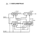
図7は、この実施の形態の記録装置20のSS複製防止制御信号検出部24の構成を説明するためのブロック図である。図7に示すように、この例のSS複製防止制御信号検出部23は、供給されたデジタル信号S21からスペクトラム拡散された複製防止制御信号を取り出す逆拡散部241と、この逆拡散部241により取り出された複製防止制御信号を元の複製防止制御信号に復元するデータ判定部242と、複製防止制御信号をスペクトラム拡散しているPN符号を検出するPN符号検出部243と、SS複製防止制御信号検出制御部244とを備えている。
【0060】
図7に示すように、SS複製防止制御信号検出制御部244は、記録装置20において用いられるクロック信号CLKの供給を受けて、イネーブル信号EN1、リセット信号RE1を形成し、これをPN符号検出部243に供給して、複製防止制御信号をスペクトラム拡散しているPN符号の検出処理を制御する。
【0061】
この実施の形態においてPN符号検出部243は、例えばスライディング相関器が用いられて形成されたものである。PN符号検出部243は、イネーブル信号EN1により動作が可能な状態にされる。そして、リセット信号RE1に応じたタイミング毎に、クロック信号CLKに基づいて、PN符号列を生成する。
【0062】
PN符号検出部243は、生成したPN符号列と複製防止制御信号をスペクトラム拡散しているPN符号列との相関を求めることにより、複製防止制御信号をスペクトラム拡散しているPN符号列を検出する。
【0063】
PN符号検出部243は、これにおいて生成したPN符号列と、複製防止制御信号をスペクトラム拡散しているPN符号列との相関を求めた結果を示す信号S31をSS複製防止制御信号検出制御部244に供給する。この信号S31は、上述のように、PN符号検出部243で、生成したPN符号列と複製防止制御信号をスペクトラム拡散しているPN符号列との相関を求めた結果、相関が高ければ、レベルの高い信号となり、相関が低ければ、レベルの低い信号となる。
【0064】
SS複製防止制御信号検出制御部244は、PN符号検出部243からの相関を求めた結果を示す信号S31が、予め決められたレベル以上の信号であるときには、複製防止制御信号をスペクトラム拡散しているPN符号列と、PN符号検出部243において生成したPN符号列との同期が合っている状態であって、複製防止制御信号をスペクトラム拡散しているPN符号列を検出したと判断する。その逆に、PN符号検出部243からの信号S31が、予め決められたレベル以下であれば、複製防止制御信号をスペクトラム拡散しているPN符号列と、PN符号検出部において生成したPN符号列との同期は合っていないと判断する。
【0065】
そして、PN符号検出部243において、複製防止制御信号をスペクトラム拡散しているPN符号列が検出されないときには、SS複製防止制御信号検出制御部244からのリセット信号RE1による制御を受けて、PN符号検出部243は、これより発生させるPN符号列の位相を調整し、前述の相関演算を行い、PN符号列の検出処理を繰り返す。
【0066】
また、PN符号検出部243において、複製防止制御信号をスペクトラム拡散しているPN符号列が検出されたときには、SS複製防止制御信号検出制御部244は、PN符号検出部243の検出結果に応じて、逆拡散部241においてのPN符号列の発生の開始タイミングを制御する信号CT1を形成し、この信号CT1を逆拡散部241に供給する。また、SS複製防止制御信号検出制御部244は、データ判定部242を制御する信号CT2を形成して、これをデータ判定部242に供給する。
【0067】
逆拡散部241は、図示しないがPN符号発生器や乗算回路を備えている。そして、SS複製防止制御信号検出制御部244からの信号CT1で示されるタイミング毎に、クロック信号CLKに応じてPN符号列を発生させる。そして、発生させたPN符号列を用いて、逆スペクトラム拡散を行い、広帯域、低レベルの信号とされた複製防止制御信号を、元の狭帯域、高レベルの信号として、信号S21から抽出する。抽出された複製防止制御信号S32は、データ判定部242に供給される。
【0068】
データ判定部242は、抽出された複製防止制御信号S32を復元して、複製制御部25に供給する。すなわち、複製防止制御信号S32が指示する複製制御内容を判定し、その判定結果S24を複製制御部25に供給する。
【0069】
なお、図7に示したSS複製防止制御信号検出部24のPN符号検出部243および逆拡散部241においてPN符号列を発生させるPN符号発生器は、前述した情報出力装置10のSS複製防止制御信号生成部16において用いられる図3に示したPN符号発生器と同様に形成されたものである。
【0070】
複製制御部25は、複製防止制御信号の復元結果に基づいて、書き込み部23を制御するための制御信号S25を形成し、これを書き込み部23に供給する。制御信号S25は、映像信号のディスク200への書き込みの許可あるいは禁止を制御するものである。
【0071】
書き込み部23は、複製制御部25からの制御信号S25が、複製を許可するものであるときは、符号化部22からのデジタル映像信号S22をディスク200に書き込み、制御信号S25が複製を禁止するものであるときには、デジタル映像信号S22をディスク200に書き込まないようにする。
【0072】
このように、この実施の形態の記録装置20においては、供給されるアナログ映像信号には、スペクトル拡散された複製防止制御信号が重畳されており、逆スペクトラム拡散することにより、映像信号に重畳されたこの複製防止制御信号を検出し、検出した複製防止制御信号に応じて、供給された映像信号に対する複製防止制御を行なうことができる。
【0073】
図6の例の記録装置20では、入力信号S7を、A/D変換器21によりデジタル信号に変換した後に、SS複製防止制御信号検出部24に供給するようにしたが、SS複製防止制御信号の検出は、アナログ信号S7からも行うことができる。
【0074】
図8は、その場合の例であり、情報出力装置10からの信号S7は、A/D変換器21に供給されると共に、SS複製防止制御信号検出部26に供給される。そして、SS複製防止制御信号検出部26では、信号S7中のSS複製防止制御信号にPN符号に同期したPN符号の検出が行われ、複製防止制御信号が復元される。そして、その復元結果が複製制御部25に供給される。その他は、図6の例と同様である。
【0075】
[第2の実施の形態]
図9は、この第2の実施の形態の情報出力装置30の構成例を示す図である。この例の情報出力装置30は、前述した第1の実施の形態の情報出力装置10と同様に、DVD装置の再生系に相当する。
【0076】
また、図9に示すように、この第2の実施の形態の情報出力装置30は、読み出し部31、復号化部32、D/A変換器33、加算部34、複製防止制御信号抽出部35、SS複製防止制御信号生成部36、D/A変換器37、タイミング生成部38を備えている。複製防止制御信号抽出部35、SS複製防止制御信号生成部36、D/A変換器37、タイミング生成部38以外の各部は、ディスク100を含め、前述した第1の実施の形態の情報出力装置10の対応する各部と同様のものである。
【0077】
そして、この情報出力装置30の複製防止制御信号抽出部35、SS複製防止制御信号生成部36、D/A変換器37は、図1を用いて前述した情報出力装置10の複製防止制御信号抽出部15、SS複製防止制御信号生成部16、D/A変換器17と同様の機能を有するものであるが、タイミング生成部38からのタイミング信号の供給を受けて動作するようにされている点で、図1に示した情報出力装置10の対応する各部とは異なるものである。
【0078】
この第2の実施の形態の情報出力装置30において、タイミング生成部38は、D/A変換器13からのアナログ映像信号S3の供給を受けて、このアナログ映像信号S3中の映像同期信号を基準信号として用いてクロック信号や各種のタイミング信号を生成するものである。
【0079】
図10は、このタイミング生成部38の詳細構成例を示すブロック図である。図10に示すように、タイミング生成部38は、基準タイミング検出部381と、PLL回路382と、タイミング信号生成部383とを備えている。
【0080】
基準タイミング検出部381は、D/A変換器33からのアナログ映像信号S3から、基準タイミング信号としての映像同期信号を抽出する。この実施の形態においては、基準タイミング信号として垂直同期信号を用いるもので、基準タイミング検出部381は、垂直同期信号S41を抽出し、これをPLL回路382およびタイミング信号生成部383に供給する。
【0081】
PLL回路382は、垂直同期信号S41に同期したクロック信号CLK1を生成する。このクロック信号CLK1は、タイミング信号生成部383に供給されると共に、複製防止制御信号抽出部35、SS複製防止制御信号生成部36、D/A変換器37などに、それぞれ供給される。
【0082】
タイミング信号生成部383は、垂直同期信号S41とクロック信号CLK1とに基づいて、リセット信号RE1や、その他の各種のタイミング信号を生成して出力する。この第2の実施の形態において、リセット信号RE1は、垂直同期信号に同期し、1垂直区間を1周期とする信号として生成される。
【0083】
複製防止制御信号抽出部35は、読み出し部31からの再生映像信号成分S2の情報データ列中から複製防止制御信号を抽出する。そして、タイミング生成部38からのクロック信号CLK1により、これを複製防止制御信号S4としてSS複製防止制御信号生成部36に供給する。
【0084】
SS複製防止制御信号生成部36は、複製防止制御信号S4をスペクトラム拡散するスペクトラム拡散手段としての機能を有するものである。
【0085】
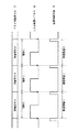
この第2の実施の形態においても、SS複製防止制御信号生成部36は、図2を用いて前述したSS複製防止制御信号生成部16と同様の構成とされている。しかし、この第2の実施の形態においては、SS複製防止制御信号生成部36には、タイミング生成部38からの映像同期信号に同期したクロック信号CLK1が供給されると共に、リセット信号として、垂直同期信号S41に同期した垂直周期のリセットRE1が供給され、SS複製防止制御信号生成部36からは、1垂直周期ごとにリセットされて繰り返すPN符号列により複製防止制御信号がスペクトラム拡散されたSS複製防止制御信号S5vが得られる。
【0086】
すなわち、この第2の実施の形態においては、SS複製防止制御信号生成部36では、図11に示すように、垂直同期信号(図11A)に同期して、1垂直区間を1周期とするリセット信号RE1(図11B)により、1垂直周期毎に、PN符号列生成部が初期化されて、1垂直周期を繰り返し周期とするPN符号列(図11C)PSvを、クロック信号CLK1に同期して発生させる。そして、このPN符号列PSvにより、複製防止制御信号S4をスペクトラム拡散して、SS複製防止制御信号S5vを生成する。
【0087】
このSS複製防止制御信号S5vがD/A変換されて、アナログSS複製防止制御信号S6vが形成され、これがアナログ映像信号S3に重畳されて、出力映像信号S7vが形成される。そして、この出力映像信号S7vが、モニタ受像機や記録装置に供給される。
【0088】
なお、上述した情報出力装置30において、タイミング生成部38は、D/A変換後のアナログ映像信号S3の供給を受けて、基準信号としての垂直同期信号を抽出し、各種のタイミング信号を生成するものとして説明したが、D/A変換前のデジタル映像信号の供給を受けて、このデジタル映像信号から基準信号としての垂直同期信号を抽出し、各種のタイミング信号やクロック信号を生成するようにしてもよい。
【0089】
次に、上述の情報出力装置30からの出力信号の供給を受けて、情報を記録する記録装置について説明する。
【0090】
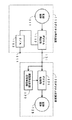
図12は、この第2の実施の形態の情報複製防止システムで用いられる記録装置40を説明するための図である。記録装置40は、この実施の形態において、DVD装置の記録系に相当する。
【0091】
この実施の形態の記録装置40は、図12に示すように、A/D変換器41、符号化部42、書き込み部43、SS複製防止制御信号検出部44、複製の許可/禁止を制御する複製制御部45、タイミング生成部46を備えており、SS複製防止制御信号検出部44、タイミング生成部46以外の各部は、ディスク200を含め、前述の図6に示した第1の実施の形態の記録装置20の対応する各部と同様のものである。
【0092】
そして、この記録装置40のSS複製防止制御信号検出部44は、前述の記録装置20のSS複製防止制御信号検出部24と同様に、逆スペクトラム拡散を行なう機能を有するものであるが、後述するように、逆スペクトラム拡散に用いる逆拡散用のPN符号列の発生の開始タイミングがタイミング生成部46からのリセット信号により制御される。
【0093】
前述したように、情報出力装置30においては、映像信号中の垂直同期信号に同期し、1垂直区間を1周期とするリセット信号RE1に基づいてPN符号列PSvを生成し、このPN符号列PSvを用いて、複製防止制御信号列をスペクトラム拡散している。
【0094】
このため、記録装置40においても、情報出力装置30から供給される映像信号中の垂直同期信号に基づいて、逆スペクトラム拡散に用いる逆拡散用のPN符号列を1垂直区間毎に生成することにより、拡散用のPN符号列PSvと同じタイミングの逆拡散用のPN符号列を生成させることが容易にできる。
【0095】
この第2の実施の形態の記録装置40のタイミング生成部46は、図10に示したものと同様の構成を備えており、この記録装置40の入力信号S7vの垂直同期信号に基づいて、クロック信号および逆拡散用のPN符号列の発生の開始タイミングを制御するリセット信号を生成し、これをSS複製防止制御信号検出部44に供給する。
【0096】
この場合、タイミング生成部46から得られるリセット信号は、情報出力装置30のSS複製防止制御信号生成部36において用いられたリセット信号RE1に対応する信号であり、垂直周期の信号である。したがって、このタイミング生成部46から得られるリセット信号は、リセット信号RE1に同期する信号であって、逆拡散用のPN符号列をその先頭から生成させるための信号とすることができる。このため、SS複製防止制御信号検出部44では、第1の実施の形態とは異なり、スライディング相関器などを用いた逆拡散のためのPN符号の位相制御は不要となる。
【0097】
SS複製防止制御信号検出部44は、上述したように、タイミング生成部46からのリセット信号を含むタイミング信号に基づいて、逆拡散用のPN符号列を生成し、これにより、逆スペクトラム拡散を行なうことにより、A/D変換器41からのデジタル映像信号に重畳されている複製防止制御信号を復元し、これを複製制御部45に供給する。
【0098】
このように、この第2の実施の形態においては、垂直同期信号を基準信号とした、垂直周期のPN符号列を用いてスペクトラム拡散および逆スペクトラム拡散を行う。したがって、記録装置40においては、垂直同期信号に同期したリセット信号を生成して、容易に逆拡散用のPN符号列を生成することができるので、逆スペクトラム拡散を迅速に実行し、迅速にスペクトラム拡散されて映像信号に重畳されている複製防止制御信号を検出することができる。
【0099】
また、上述した記録装置40において、タイミング生成部46は、A/D変換後のデジタル映像信号S41の供給を受けて、各種のタイミング信号を生成するようにしたが、A/D変換前のアナログ映像信号S7vの供給を受けて、このアナログ映像信号S7vから基準信号としての垂直同期信号を抽出し、クロック信号やリセット信号などのタイミング信号を生成するようにしてもよい。
【0100】
また、この第2の実施の形態においては、前述のように、拡散用、逆拡散用のPN符号列は、1垂直区間毎に生成する場合に限らず、2垂直区間毎、4垂直区間毎のように複数垂直区間毎に生成するようにしてもよいし、1/2垂直区間毎、1/4垂直区間毎のように1垂直区間を複数に分割し、1分割区間毎、複数分割区間毎に生成するようにしてもよい。
【0101】
また、映像同期信号は、垂直同期信号に限るものではなく、水平同期信号を用いるようにしてもよい。この場合にも、拡散用、逆拡散用のPN符号列を複数水平区間毎に生成するようにしてもよいし、1水平区間を複数に分割し、1分割区間毎、複数分割区間毎に生成するようにしてもよい。
【0102】
[情報出力装置のSS複製防止制御信号生成部の他の例]
以上の実施の形態では、一つのPN符号により、1ビットや2ビットなどの低ビットの複製防止制御信号をスペクトラム拡散して、SS複製防止制御信号を生成するようにしたが、以下に説明するように、複製防止制御信号をスペクトラム拡散するのではなく、PN符号そのものやPN符号と他の符号との混合を、複製防止制御信号が指示する制御内容に応じて伝送することもできる。
【0103】
図13の例は、位相の異なるPN符号を用いたSS複製防止制御信号生成部の一実施例である。
【0104】
この例においては、PN符号発生部1001から出力されるPN符号PSは、選択部1003に供給されると共に、シフトレジスタ1002に供給される。このシフトレジスタ1002からは、PN符号PSがクロック信号により順次にタイムシフトされた、位相が順次に異なるPN符号PSa、PSb、…、PSnが出力されて、それぞれ選択部1003に供給される。
【0105】
そして、選択部1003には、選択制御信号として複製防止制御信号FSが供給される。選択部1003は、複数の位相のPN符号PS,PSa,PSb,…,PSnのうちから、選択制御信号である複製防止制御信号の制御内容、つまり、複製禁止や複製許可などに応じた、一つの位相のPN符号を選択して、SS複製防止制御信号として出力する。
【0106】
図14の例は、異なる系列のPN符号を用いた場合のSS複製防止制御信号生成部の一実施例である。
【0107】
この例では、それぞれ異なる系列のPN符号PS1,PS2,…,PS3を生成する複数個のPN符号生成部1021、1022、…、1023が設けられる。そして、各PN符号生成部1021、1022、…、1023の出力は、選択部1024に入力される。
【0108】
そして、選択部1024には、選択制御信号として複製防止制御信号FSが供給される。選択部1024は、複数の系列のPN符号PS1,PS2,…,PS3のうちから、選択制御信号である複製防止制御信号の制御内容、つまり、複製禁止や複製許可などに応じた、一つの系列のPN符号を選択して、SS複製防止制御信号として出力する。
【0109】
図15の例は、1種類のPN符号と、複数の直交符号を用いた場合のSS複製防止制御信号生成部の一実施例である。
【0110】
この例では、1個のPN符号生成部1041と、互いに異なる直交符号を生成する直交符号生成部1042、1043、…、1044が設けられる。そして、PN符号生成部1041の出力PN符号PSは、乗算部1046に入力される。また、直交符号生成部1042、1043、…、1044からの、異なる直交符号は、選択部1045に入力される。また、選択部1045には、選択制御信号として複製防止制御信号FSが供給される。
【0111】
選択部1045は、複数の異なる直交符号から、選択制御信号である複製防止制御信号の制御内容、つまり、複製禁止や複製許可などに応じた、一つの直交符号を乗算部1046に出力する。乗算部1046では、PN符号PSと、選択された直交符号が乗じられて、その乗算結果が、SS複製防止制御信号として出力される。
【0112】
[SS複製防止制御信号生成部の他の例に対応するSS複製防止制御信号検出部の例]
図16の例は、図13の例の異なる位相のPN符号が用いられたSS複製防止制御信号が重畳された映像信号を受信する記録装置のSS複製防止制御信号検出部の一実施例である。
【0113】
この例のSS複製防止制御信号検出部では、A/D変換されてデジタル信号とされたSS複製防止制御信号が重畳された受信信号は、PN符号検出部1061に入力される。このPN符号検出部1061では、PN符号のタイミングが検出され、その結果が複製防止制御情報生成部1062に入力される。複製防止制御情報生成部1062は、PN符号のタイミングの違いから、複製防止制御情報が指示する制御内容を特定し、その特定結果に応じて、複製制御部に供給する複製制御情報を生成し、出力する。
【0114】
図17の例は、図14の例の異なる系列のPN符号あるいは図15の例の1種類のPN符号と複数の直交符号を組み合わせた符号が用いられたSS複製防止制御信号が重畳された映像信号を受信する記録装置のSS複製防止制御信号検出部の一実施例である。
【0115】
この例のSS複製防止制御信号検出部では、A/D変換されてデジタル信号とされたSS複製防止制御信号が重畳された受信信号は、PN符号検出部1081、1082、…、1083に入力される。PN符号検出部1081、1082、…、1083のそれぞれは、それぞれ異なるPN符号または1種類のPN符号と異なる直交符号を掛け合わせた符号を検出する。その出力は複製防止制御情報生成部1084に入力される。複製防止制御情報再生部1084は、どの符号列が検出されたかをもとに、複製防止制御情報の種類を特定し、その特定結果に応じて、複製制御部に供給する複製制御情報を生成し、出力する。
【0116】
以上のようなSS複製防止制御信号生成部およびSS複製防止制御信号検出部を用いた場合には、重畳させる複製制御情報を生成するスペクトラム拡散において、異なる位相のPN符号あるいは直交符号とPN符号とを組み合わせた符号を用いることで、複数の複製制御情報を同時に付加することも可能である。
【0117】
なお、上述の第1および第2の実施の形態においては、M系列のPN符号を用いるようにしたが、これに限るものではなく、Gold符号系列の符号など各種の拡散符号を用いることができる。
【0118】
また、以上の例は、情報信号が映像信号の場合であるが、オーディオ信号やその他の複製を防止する要求が生じるすべての情報の複製防止制御に、この発明は適用可能である。
【0119】
また、以上の説明では、記録媒体に、予め複製防止制御情報がデジタル信号の形式で記録されている場合について説明したが、記録媒体に記録されている情報がアナログ情報であって、前述したAGC方式やAPC方式による消極的な複製防止対策が施されている記録媒体を再生して情報を出力する情報出力装置にも、この発明は適用可能である。
【0120】
すなわち、その場合には、情報出力装置は、複製防止制御信号の発生部を備え、例えば、前述のAGC方式のための大振幅の疑似同期信号を検知したときに、この複製防止制御信号を発生させて上述のように、これをスペクトラム拡散して、アナログ出力情報信号に重畳して出力するようにする。このようにすれば、記録媒体には、複製防止制御信号が記録されていない場合にも、複製防止制御を確実に行わせるようにすることができる。
【0121】
同様に、デジタル信号の形式で情報が記録されている記録媒体であって、付加情報として著作権情報は記録されていても、直接的な複製防止制御情報が記録されていない記録媒体を再生を行う情報出力装置においても、再生に際して、付加情報としての前記著作権情報を検知したときに、複製防止制御信号を発生させて上述のように、これをスペクトラム拡散して、アナログ出力情報信号に重畳して出力するようにすれば、アナログ接続の場合において、記録装置における複製防止制御を確実に行わせるようにすることができる。
【0122】
【発明の効果】
以上説明したように、この発明では、再生装置などの情報出力装置から出力するアナログ情報信号に対し、複製防止制御信号をスペクトラム拡散することにより周波数帯域を広げ、アナログ情報信号と同一時間、同一周波数内で重畳させたので、周波数フィルタや単純な情報信号の置き換えでは複製制御情報の削除および修正が不可能となる。このため、アナログ接続であっても、有効に複製防止制御を行うことができる。
【0123】
そして、複製防止制御信号は、スペクトラム拡散して、低信号レベルで重畳させるようにすることができるため、アナログ情報信号に対して劣化等の影響をほとんど与えることがない。
【0124】
また、重畳させる複製制御情報を生成するスペクトラム拡散において、異なる位相のPN符号あるいは直交符号とPN符号を組み合わせた符号を用いることで、複数の複製制御情報を同時に付加することも可能である。
【図面の簡単な説明】
【図1】この発明による情報出力装置の一実施の形態を説明するためのブロック図である。
【図2】図1の実施の形態中のSS複製防止制御信号生成部を説明するためのブロック図である。
【図3】図2の一部のPN符号列生成部の一例を説明するためのブロック図である。
【図4】SS複製防止制御信号と情報信号の関係をスペクトルで示した図である。
【図5】この発明による情報出力装置の一実施の形態の他の例を説明するためのブロック図である。
【図6】この発明による情報記録装置の一実施の形態を説明するためのブロック図である。
【図7】図6の実施の形態におけるSS複製防止制御信号検出部の一例を示すブロック図である。
【図8】この発明による情報記録装置の一実施の形態の他の例を説明するためのブロック図である。
【図9】この発明による情報出力装置の一実施の形態の他の例を説明するためのブロック図である。
【図10】図9の実施の形態におけるタイミング生成部の例を示すブロック図である。
【図11】図9の実施の形態の要部の原理を説明するためのタイミングチャートを示す図である。
【図12】この発明による情報記録装置の一実施の形態の他の例を説明するためのブロック図である。
【図13】この発明による情報出力装置に用いられるSS複製防止制御信号生成部の他の例を示すブロック図である。
【図14】この発明による情報出力装置に用いられるSS複製防止制御信号生成部の他の例を示すブロック図である。
【図15】この発明による情報出力装置に用いられるSS複製防止制御信号生成部の他の例を示すブロック図である。
【図16】この発明による情報記録装置に用いられるSS複製防止制御信号検出部の他の例を示すブロック図である。
【図17】この発明による情報記録装置に用いられるSS複製防止制御信号検出部の他の例を示すブロック図である。
【図18】複製防止制御システムの従来の構成を説明するためのブロック図である。
【符号の説明】
10…情報出力装置、11および31…読み出し部、12および32…復号化部、13および33…D/A変換器、14および34…加算部、15および35…複製防止制御信号抽出部、16および36…SS複製防止制御信号生成部、17および37…D/A変換器、20…情報記録装置、21および41…A/D変換器、22および42…符号化部、23および43…書き込み部、24および44…SS複製防止制御信号検出部、25および45…複製制御部、25…タイミング生成部、38…タイミング生成部、40…情報記録装置、46…タイミング生成部、100…出力側記録媒体、161…複製防止制御信号生成部、162…PN符号列生成部、200…記録側記録媒体、241…逆拡散部、242…データ判定部、243…PN符号検出部、244…複製防止制御信号検出制御部[0001]
BACKGROUND OF THE INVENTION
For example, the present invention reproduces an information signal recorded on a recording medium, transmits it in an analog signal state together with information for preventing duplication, receives the transmitted information signal, and records it on another recording medium The present invention relates to a method and device for restricting or prohibiting the operation, and an information output device used therefor.
[0002]
[Prior art]
VTRs (video tape recorders) have become widespread, and a lot of software that can be played back by VTRs has been provided. Recently, playback devices for digital VTRs and DVDs (digital video discs) have become a reality, and it has become possible to easily reproduce and view video and audio with good image quality and sound quality. ing.
[0003]
However, on the other hand, there is a problem that there is a possibility that the software that has been provided abundantly may be copied indefinitely, and various measures for preventing duplication have been conventionally taken.
[0004]
For example, although it is not a method of directly prohibiting duplication of an analog video signal, for example, a difference between an AGC (auto gain control) system of a VTR as a recording apparatus and an AGC (auto gain control) system of a monitor receiver that provides video, or APC There is a method for substantially preventing duplication by utilizing the difference in the characteristics of (Auto Phase Control).
[0005]
That is, for example, the VTR performs AGC with a pseudo-synchronization signal inserted in the video signal, and the monitor receiver uses the difference in the AGC method, such as employing an AGC method that does not depend on this pseudo-synchronization signal. The method is the former example. When an analog video signal is recorded on the original recording medium, a pseudo sync signal having an extremely large level is inserted as a sync signal for AGC, and the reproduction VTR is changed to the recording VTR. A pseudo synchronization signal having an extremely large level is inserted as a synchronization signal for AGC into the supplied video signal.
[0006]
In addition, the VTR performs APC based on the phase of the color burst signal itself in the video signal, and the monitor receiver adopts a different APC method, and the latter method uses the difference in APC characteristics. For example, when an analog video signal is recorded on an original recording medium, the phase of the color burst signal of the video signal is partially inverted, and the color burst signal is supplied as the video signal supplied from the playback VTR to the recording VTR. Is output in which the phase of is partially inverted.
[0007]
In the case described above, the monitor receiver that receives the analog video signal supplied from the reproduction VTR is affected by the partial synchronization of the phase of the pseudo-sync signal or the color burst signal used for APC. The video is played normally.
[0008]
However, in a VTR in which a pseudo sync signal is inserted from a reproduction VTR as described above or an analog video signal that has undergone phase inversion control of a color burst signal is supplied and recorded on a recording medium. The gain control or the phase control based on the input signal cannot be normally performed, and the video signal cannot be normally recorded. Therefore, even when the recorded video signal is reproduced, a normal video that can be viewed can be prevented from being reproduced.
[0009]
When analog video signals are handled in this way, duplication is not prohibited, but reproduction video that can be normally viewed is not obtained, which is a negative anti-duplication control.
[0010]
On the other hand, when dealing with digitized information such as a video signal, a copy prevention control signal made up of a copy prevention code or a copy generation restriction code is added to the video signal as digital data and added to the recording medium. By recording, direct copy prevention control such as prohibition of copy is performed.
[0011]
FIG. 18 is a basic configuration diagram of a duplicating apparatus in the case of handling this digitized information. The digital information reproduced by the digital reproducing apparatus 110 is sent to the digital recording apparatus 120 through the
[0012]
In addition to the digital main information, copy prevention control information as additional information is recorded on the recording medium 111 loaded in the digital playback device 110. This anti-duplication control information indicates, as control contents, duplication prohibition, duplication permission, generation restriction, and the like. The
[0013]
The anti-duplication
[0014]
The
[0015]
Further, when the determination result of the anti-duplication control signal from the anti-duplication control
[0016]
Thus, in the case of so-called digital connection in which the main information signal and the anti-duplication control signal as additional information are supplied as digital signals to the recording apparatus, the anti-duplication control signal is included in the transmitted digital data. Therefore, the copy prevention control such as copy prohibition can be surely performed in the recording apparatus by using the copy prevention control signal.
[0017]
[Problems to be solved by the invention]
By the way, when the digital playback device of FIG. 18 is a digital VTR, for example, only the video signal and audio signal which are main information signals are passed through the D /
[0018]
As described above, even in the digital information reproducing apparatus, the analog signal derived to the analog output terminal 114 does not include the copy prevention control signal. For this reason, in the case of analog connection in which an analog VTR or the like is connected to the analog output terminal 114, the information signal can be duplicated.
[0019]
Therefore, it is conceivable to add a duplication prevention control signal to the D / A converted video signal or audio signal. However, the duplication prevention control signal can be used without degrading the D / A converted video signal or audio signal. It is difficult to take out in the recording apparatus and use it for anti-duplication control.
[0020]
Therefore, conventionally, in the case of an analog connection, passive copy prevention is performed by using a copy prevention method that utilizes the above-described difference between the AGC method of the VTR and the monitor receiver or the difference in the characteristics of the APC. There was only a way to do it.
[0021]
However, in the case of the anti-duplication control method using the difference in the AGC method between the VTR and the monitor receiver, or the difference in the APC characteristic, the video signal may not be displayed normally depending on the AGC method and the APC characteristic on the recording apparatus side. In some cases, it is impossible to prevent passive copying. In addition, there is a possibility that problems such as disturbance of the reproduced image on the monitor receiver may occur.
[0022]
Even if the signal input to the recording device for duplication is an analog signal, the present invention is not a negative duplication prevention measure as described above, and does not deteriorate the reproduction quality of the analog information signal. An object of the present invention is to allow the duplication prevention control information to be superimposed on an analog information signal and transmitted to the recording apparatus side.
[0023]
[Means for Solving the Problems]
In order to solve the above problem, in the present invention,
In an information output device that superimposes a spreading code on a main information signal and outputs it,
Means for generating a plurality of spreading codes having different phases;
Means for selecting a spread code having a phase corresponding to the control content of the anti-duplication control signal from the plurality of spread codes;
Output means for outputting the selected spreading code superimposed on the main information signal;
An information output device is provided.
[0024]
In addition, the present invention provides an information output device that outputs a superposed spread code on a main information signal.
Means for generating a plurality of spreading codes of different sequences;
Means for selecting a spreading code of a sequence corresponding to the control content of the anti-duplication control signal from the plurality of spreading codes;
Output means for outputting the selected spreading code superimposed on the main information signal;
An information output device is provided.
[0027]
In the present invention, a plurality of anti-duplication control information can be simultaneously added to the main information signal by using spreading codes of different phases or sequences as the anti-duplication control information to be superimposed on the main information signal.
[0028]
DETAILED DESCRIPTION OF THE INVENTION
Embodiments of the present invention will be described below with reference to the drawings.
[0029]
An information duplication prevention system formed by an information output apparatus and a recording apparatus according to an embodiment described below is an application of the information duplication prevention control method according to the present invention. In the embodiments described below, the information output device and the recording device are described as being applied to a DVD (digital video disk) recording / reproducing device (hereinafter referred to as a DVD device). Note that the description of the audio signal system is omitted for the sake of simplicity.
[0030]
[First Embodiment]
FIG. 1 is a diagram for explaining an
[0031]
In FIG. 1, a
[0032]
In this embodiment, the anti-duplication control signal is information indicating prohibition or permission of duplication of video signals or generation limitation, and is added to video data. The
[0033]
As shown in FIG. 1, the
[0034]
The
[0035]
The
[0036]
The anti-duplication control
[0037]
The SS anti-duplication control
[0038]
FIG. 2 is a diagram illustrating a configuration example of the SS duplication prevention control
[0039]
The anti-duplication control signal sequence generation unit 161 is supplied with the clock signal CLK and the anti-duplication control signal S4 and the timing signal T1 from the anti-duplication control
[0040]
Then, the anti-duplication control signal sequence generation unit 161 generates the anti-duplication control signal sequence FS by outputting the anti-duplication control signal S4 for each bit by a predetermined number of clocks, and the multiplier 163 To supply. In the case of this example, for example, a 1-bit or 2-bit low-bit duplication prevention control signal sequence FS for instructing duplication prohibition or duplication permission is generated for each section of one vertical cycle.
[0041]
The PN
[0042]
The PN code
[0043]
FIG. 3 is a diagram illustrating a configuration example of the PN code
[0044]
The multiplier 163 uses the PN code string PS from the PN
[0045]
The SS anti-duplication control signal S5 obtained from the SS anti-duplication
[0046]
The
[0047]
FIG. 4 shows the relationship between the anti-duplication control signal and the information signal, in this example, the video signal, as a spectrum. The anti-duplication control signal contains a small amount of information and is a low bit rate signal, and is a narrow-band signal as shown in FIG. When spectrum spread is applied to this, a signal having a wide bandwidth as shown in FIG. At this time, the spread spectrum signal level decreases in inverse proportion to the band expansion ratio.
[0048]
The spread spectrum signal, that is, the SS duplication prevention control signal S6 is superimposed on the information signal by the
[0049]
However, as will be described later, when the spectrum despreading is performed to detect the SS duplication prevention control signal on the recording side, the SS duplication prevention control signal is again converted into a narrow-band signal as shown in FIG. Restored. By providing a sufficient band spreading factor, the power of the anti-duplication control signal after despreading exceeds the information signal and can be detected.
[0050]
In this case, the SS anti-duplication control signal S6 superimposed on the analog video signal is superimposed on the same time and within the same frequency as the analog video signal, and therefore cannot be deleted or modified by replacing the frequency filter or simple information. is there.
[0051]
Therefore, the SS duplication prevention control signal superimposed on the video signal is not removed, and the SS duplication prevention control signal can be reliably provided to devices such as a monitor receiver and a recording device.
[0052]
In the example of FIG. 1, after the decoded video signal is converted into an analog signal, the D / A converted SS duplication prevention control signal S6 is superimposed on the analog video signal. However, the
[0053]
Next, a description will be given of a recording apparatus that records information upon receiving an output signal from the
[0054]
FIG. 6 is a diagram illustrating a configuration example of an example of the recording device 20 used in the information duplication prevention system according to this embodiment. The recording device 20 corresponds to the recording system of the DVD device in this embodiment.
[0055]
As shown in FIG. 6, the recording apparatus 20 of this embodiment controls an A /
[0056]
An analog video signal S7 supplied from the
[0057]
The
[0058]
The SS anti-duplication control
[0059]
FIG. 7 is a block diagram for explaining the configuration of the SS duplication prevention control
[0060]
As shown in FIG. 7, the SS duplication prevention control signal detection control unit 244 receives the supply of the clock signal CLK used in the recording apparatus 20 and forms an enable signal EN1 and a reset signal RE1, which are converted into a PN code detection unit. 243 is supplied to control the detection processing of the PN code that has spread the anti-duplication control signal.
[0061]
In this embodiment, the PN code detector 243 is formed using, for example, a sliding correlator. The PN code detector 243 is enabled by the enable signal EN1. Then, at each timing according to the reset signal RE1, a PN code string is generated based on the clock signal CLK.
[0062]
The PN code detection unit 243 detects a PN code string in which the anti-duplication control signal is spread by obtaining a correlation between the generated PN code string and the PN code string in which the anti-duplication control signal is spread spectrum. .
[0063]
The PN code detection unit 243 generates a signal S31 indicating the correlation between the PN code string generated in this process and the PN code string obtained by spectrum-spreading the anti-duplication control signal as an SS anti-duplication control signal detection control unit 244. To supply. As described above, the signal S31 is obtained when the PN code detection unit 243 obtains a correlation between the generated PN code string and the PN code string obtained by spectrum-spreading the anti-duplication control signal. If the correlation is low, the signal becomes a low level signal.
[0064]
The SS anti-duplication control signal detection control unit 244 performs spectrum spreading on the anti-duplication control signal when the signal S31 indicating the result of obtaining the correlation from the PN code detection unit 243 is a signal of a predetermined level or higher. It is determined that the PN code string in which the PN code string generated by the PN code detection unit 243 is synchronized and the PN code string in which the anti-duplication control signal is spread is detected. On the contrary, if the signal S31 from the PN code detection unit 243 is equal to or lower than a predetermined level, the PN code sequence in which the anti-duplication control signal is spread and the PN code sequence generated by the PN code detection unit. It is determined that the synchronization with is not correct.
[0065]
When the PN code detection unit 243 does not detect a PN code string that is spread spectrum of the anti-duplication control signal, the PN code detection is performed under the control of the reset signal RE1 from the SS anti-duplication control signal detection control unit 244. The unit 243 adjusts the phase of the PN code string generated thereby, performs the above-described correlation calculation, and repeats the PN code string detection process.
[0066]
In addition, when the PN code detection unit 243 detects a PN code string in which the anti-duplication control signal is spread in spectrum, the SS anti-duplication control signal detection control unit 244 responds to the detection result of the PN code detection unit 243. The signal CT1 for controlling the start timing of generation of the PN code string in the
[0067]
The
[0068]
The
[0069]
The PN code generator that generates the PN code string in the PN code detection unit 243 and the
[0070]
Based on the restoration result of the anti-duplication control signal, the
[0071]
When the control signal S25 from the
[0072]
As described above, in the recording apparatus 20 of this embodiment, the supplied analog video signal is superimposed with the spread spectrum anti-duplication control signal, and is superimposed on the video signal by inverse spectrum spreading. The anti-duplication control signal can be detected, and anti-duplication control can be performed on the supplied video signal in accordance with the detected anti-duplication control signal.
[0073]
In the recording apparatus 20 in the example of FIG. 6, the input signal S7 is converted into a digital signal by the A /
[0074]
FIG. 8 shows an example in that case, and the signal S7 from the
[0075]
[Second Embodiment]
FIG. 9 is a diagram illustrating a configuration example of the information output device 30 according to the second embodiment. The information output device 30 in this example corresponds to a playback system of a DVD device, similar to the
[0076]
As shown in FIG. 9, the information output device 30 of the second embodiment includes a reading unit 31, a
[0077]
Then, the anti-duplication control
[0078]
In the information output device 30 of the second embodiment, the
[0079]
FIG. 10 is a block diagram illustrating a detailed configuration example of the
[0080]
The reference
[0081]
The
[0082]
The
[0083]
The anti-duplication control
[0084]
The SS anti-duplication control
[0085]
Also in the second embodiment, the SS anti-duplication
[0086]
That is, in the second embodiment, the SS duplication prevention
[0087]
This SS duplication prevention control signal S5v is D / A converted to form an analog SS duplication prevention control signal S6v, which is superimposed on the analog video signal S3 to form an output video signal S7v. The output video signal S7v is supplied to a monitor receiver or a recording device.
[0088]
In the information output device 30 described above, the
[0089]
Next, a recording apparatus for recording information upon receiving an output signal from the information output apparatus 30 will be described.
[0090]
FIG. 12 is a diagram for explaining the recording apparatus 40 used in the information duplication prevention system according to the second embodiment. The recording device 40 corresponds to the recording system of the DVD device in this embodiment.
[0091]
As shown in FIG. 12, the recording apparatus 40 of this embodiment controls an A / D converter 41, an encoding unit 42, a
[0092]
The SS duplication prevention control signal detection unit 44 of the recording device 40 has a function of performing reverse spectrum spreading, similar to the SS duplication prevention control
[0093]
As described above, the information output device 30 generates the PN code string PSv based on the reset signal RE1 that is synchronized with the vertical synchronization signal in the video signal and has one vertical section as one cycle, and this PN code string PSv. Is used to spread the anti-duplication control signal sequence.
[0094]
For this reason, the recording apparatus 40 also generates a despreading PN code string for despread spectrum for each vertical section based on the vertical synchronization signal in the video signal supplied from the information output apparatus 30. Therefore, it is possible to easily generate a PN code string for despreading at the same timing as the PN code string PSv for spreading.
[0095]
The
[0096]
In this case, the reset signal obtained from the
[0097]
As described above, the SS duplication prevention control signal detection unit 44 generates a PN code string for despreading based on the timing signal including the reset signal from the
[0098]
As described above, in the second embodiment, spread spectrum and inverse spectrum spread are performed using a vertical period PN code string using a vertical synchronization signal as a reference signal. Therefore, in the recording device 40, a reset signal synchronized with the vertical synchronization signal can be generated, and a PN code string for despreading can be easily generated. The anti-duplication control signal that is spread and superimposed on the video signal can be detected.
[0099]
In the recording apparatus 40 described above, the
[0100]
In the second embodiment, as described above, the PN code sequences for spreading and despreading are not limited to being generated for each vertical section, but for every two vertical sections, for every four vertical sections. Or may be generated for each of a plurality of vertical sections, or one vertical section may be divided into a plurality of divided sections such as every 1/2 vertical section and every 1/4 vertical section. You may make it produce | generate for every.
[0101]
The video synchronization signal is not limited to the vertical synchronization signal, and a horizontal synchronization signal may be used. Also in this case, the PN code string for spreading and despreading may be generated for each of a plurality of horizontal sections, or one horizontal section is divided into a plurality of sections and generated for each of the divided sections and each of the plurality of divided sections. You may make it do.
[0102]
[Another example of SS duplication prevention control signal generation unit of information output device]
In the above embodiment, the SS anti-duplication control signal is generated by spectrum-spreading the low-bit anti-duplication control signal such as 1 bit or 2 bits with one PN code, which will be described below. As described above, instead of spectrum spreading of the anti-duplication control signal, the PN code itself or a mixture of the PN code and another code can be transmitted according to the control content instructed by the anti-duplication control signal.
[0103]
The example of FIG. 13 is an embodiment of the SS duplication prevention control signal generation unit using PN codes having different phases.
[0104]
In this example, the PN code PS output from the PN
[0105]
The
[0106]
The example of FIG. 14 is an example of the SS duplication prevention control signal generation unit when different series of PN codes are used.
[0107]
In this example, a plurality of PN
[0108]
The
[0109]
The example of FIG. 15 is an example of the SS duplication prevention control signal generator when one type of PN code and a plurality of orthogonal codes are used.
[0110]
In this example, one PN
[0111]
The
[0112]
[Example of SS duplication prevention control signal detection unit corresponding to another example of SS duplication prevention control signal generation unit]
The example of FIG. 16 is an example of an SS duplication prevention control signal detection unit of a recording apparatus that receives a video signal on which an SS duplication prevention control signal using PN codes having different phases as in the example of FIG. 13 is superimposed. .
[0113]
In the SS duplication prevention control signal detection unit of this example, the received signal on which the SS duplication prevention control signal converted into a digital signal by A / D conversion is superimposed is input to the PN code detection unit 1061. The PN code detection unit 1061 detects the timing of the PN code, and the result is input to the anti-duplication control
[0114]
The example of FIG. 17 is an image in which an SS duplication prevention control signal using a PN code of a different series of the example of FIG. 14 or a combination of one kind of PN code of the example of FIG. 15 and a plurality of orthogonal codes is superimposed. It is one Example of SS duplication prevention control signal detection part of the recording device which receives a signal.
[0115]
In the SS duplication prevention control signal detection unit of this example, the reception signal on which the SS duplication prevention control signal converted into a digital signal by A / D conversion is superimposed is input to the PN code detection units 1081, 1082,. The Each of the PN code detection units 1081, 1082,..., 1083 detects a code obtained by multiplying a different PN code or a single type of PN code and a different orthogonal code. The output is input to the anti-duplication control information generation unit 1084. The anti-duplication control information reproducing unit 1084 identifies the type of anti-duplication control information based on which code string is detected, and generates duplication control information to be supplied to the duplication control unit according to the identification result. ,Output.
[0116]
In the case of using the SS anti-duplication control signal generation unit and the SS anti-duplication control signal detection unit as described above, in spread spectrum for generating duplication control information to be superimposed, PN codes of different phases or orthogonal codes and PN codes It is also possible to add a plurality of duplication control information at the same time by using a code that combines.
[0117]
In the first and second embodiments described above, the M-sequence PN code is used. However, the present invention is not limited to this, and various spreading codes such as Gold code sequence codes can be used. .
[0118]
In addition, the above example is a case where the information signal is a video signal, but the present invention can be applied to the anti-duplication control of all information in which there is a request to prevent duplication of the audio signal and other.
[0119]
In the above description, the case where the anti-duplication control information is recorded in advance in the form of a digital signal on the recording medium has been described. However, the information recorded on the recording medium is analog information, and the AGC described above is used. The present invention can also be applied to an information output apparatus that reproduces a recording medium on which passive copy prevention measures are taken by the APC method or the APC method and outputs information.
[0120]
That is, in this case, the information output apparatus includes a copy prevention control signal generator, and generates the copy prevention control signal when, for example, a large-amplitude pseudo-synchronization signal for the AGC method is detected. As described above, this is spectrum-spread and superimposed on the analog output information signal for output. In this way, it is possible to reliably perform the copy prevention control even when the copy prevention control signal is not recorded on the recording medium.
[0121]
Similarly, a recording medium on which information is recorded in the form of a digital signal, in which copyright information is recorded as additional information but no direct copy prevention control information is recorded, is reproduced. Also in the information output apparatus that performs the reproduction, when the copyright information as additional information is detected during reproduction, a copy prevention control signal is generated and spread as described above and superimposed on the analog output information signal. Thus, in the case of analog connection, it is possible to reliably perform the copy prevention control in the recording apparatus.
[0122]
【The invention's effect】
As described above, in the present invention, the analog information signal output from the information output device such as the playback device is spread by spreading the anti-duplication control signal to the same time and the same frequency as the analog information signal. Therefore, it is impossible to delete and modify the copy control information by replacing the frequency filter or a simple information signal. For this reason, even if it is an analog connection, duplication prevention control can be performed effectively.
[0123]
Since the anti-duplication control signal can be spectrum-spread and superimposed at a low signal level, the analog information signal is hardly affected by deterioration or the like.
[0124]
Further, in spread spectrum for generating duplicate control information to be superimposed, a plurality of duplicate control information can be simultaneously added by using a PN code having a different phase or a code combining an orthogonal code and a PN code.
[Brief description of the drawings]
FIG. 1 is a block diagram for explaining an embodiment of an information output apparatus according to the present invention;
2 is a block diagram for explaining an SS duplication prevention control signal generation unit in the embodiment of FIG. 1; FIG.
FIG. 3 is a block diagram for explaining an example of a part of the PN code string generation unit in FIG. 2;
FIG. 4 is a spectrum diagram showing the relationship between an SS duplication prevention control signal and an information signal.
FIG. 5 is a block diagram for explaining another example of the embodiment of the information output apparatus according to the present invention;
FIG. 6 is a block diagram for explaining an embodiment of an information recording apparatus according to the present invention.
7 is a block diagram illustrating an example of an SS duplication prevention control signal detection unit in the embodiment of FIG. 6;
FIG. 8 is a block diagram for explaining another example of the embodiment of the information recording apparatus according to the present invention.
FIG. 9 is a block diagram for explaining another example of the embodiment of the information output apparatus according to the present invention;
10 is a block diagram illustrating an example of a timing generation unit in the embodiment of FIG.
11 is a timing chart for explaining the principle of the main part of the embodiment of FIG. 9;
FIG. 12 is a block diagram for explaining another example of the embodiment of the information recording apparatus according to the present invention.
FIG. 13 is a block diagram showing another example of an SS duplication prevention control signal generator used in the information output apparatus according to the present invention.
FIG. 14 is a block diagram showing another example of an SS duplication prevention control signal generator used in the information output apparatus according to the present invention.
FIG. 15 is a block diagram showing another example of an SS duplication prevention control signal generator used in the information output apparatus according to the present invention.
FIG. 16 is a block diagram showing another example of the SS duplication prevention control signal detection unit used in the information recording apparatus according to the present invention.
FIG. 17 is a block diagram showing another example of the SS anti-duplication control signal detection unit used in the information recording apparatus according to the present invention.
FIG. 18 is a block diagram for explaining a conventional configuration of the anti-duplication control system.
[Explanation of symbols]
DESCRIPTION OF
Claims (6)
位相の異なる複数の拡散符号を生成する手段と、
上記複数の拡散符号のうちから、複製防止制御信号の制御内容に対応した位相の拡散符号を選択する手段と、
上記選択した拡散符号を上記主情報信号に重畳して出力する出力手段と、
を備えることを特徴とする情報出力装置。In an information output device that superimposes a spreading code on a main information signal and outputs it,
Means for generating a plurality of spreading codes having different phases;
Means for selecting a spread code having a phase corresponding to the control content of the anti-duplication control signal from the plurality of spread codes;
Output means for outputting the selected spreading code superimposed on the main information signal;
An information output device comprising:
位相の異なる複数の拡散符号を生成するステップと、
上記複数の拡散符号のうちから、複製防止制御信号の制御内容に対応した位相の拡散符号を選択するステップと、
上記選択した拡散符号を上記主情報信号に重畳して出力するステップと
からなることを特徴とする情報出力方法。In the information output method of superimposing the spreading code on the main information signal and outputting it,
Generating a plurality of spreading codes having different phases;
Selecting a spreading code having a phase corresponding to the control content of the anti-duplication control signal from the plurality of spreading codes;
And a step of superimposing the selected spreading code on the main information signal and outputting the superimposed information.
系列の異なる複数の拡散符号を生成する手段と、
上記複数の拡散符号のうちから、複製防止制御信号の制御内容に対応した系列の拡散符号を選択する手段と、
上記選択した拡散符号を上記主情報信号に重畳して出力する出力手段と、
を備えることを特徴とする情報出力装置。In an information output device that superimposes a spreading code on a main information signal and outputs it,
Means for generating a plurality of spreading codes of different sequences;
Means for selecting a spreading code of a sequence corresponding to the control content of the anti-duplication control signal from the plurality of spreading codes;
Output means for outputting the selected spreading code superimposed on the main information signal;
An information output device comprising:
位相の異なる複数の拡散符号を生成する手段と、
上記複数の拡散符号を用いて上記情報信号との相関を計算することで、重畳されている拡散符号を検出し、該検出された拡散符号に対応した複製防止制御情報を出力する出力手段と、
上記複製防止制御情報に応じて、上記情報信号を上記記録媒体へ書き込むことを制御する書き込み手段と、
を備えることを特徴とする記録装置。In a recording apparatus that receives an information signal in which a spreading code is superimposed on a main information signal and records it on a recording medium,
Means for generating a plurality of spreading codes having different phases;
An output means for detecting a superimposed spreading code by calculating a correlation with the information signal using the plurality of spreading codes, and outputting anti-duplication control information corresponding to the detected spreading code;
Writing means for controlling writing of the information signal to the recording medium in accordance with the anti-duplication control information;
A recording apparatus comprising:
位相の異なる複数の拡散符号を生成するステップと、
上記複数の拡散符号を用いて上記情報信号との相関を計算することで、重畳されている拡散符号を検出し、該検出された拡散符号に対応した複製防止制御情報を出力する出力ステップと、
上記複製防止制御情報に応じて、上記情報信号を上記記録媒体へ書き込むことを制御するステップと
からなることを特徴とする記録方法。In a recording method for receiving an information signal in which a spread code is superimposed on a main information signal and recording it on a recording medium,
Generating a plurality of spreading codes having different phases;
An output step of detecting a superimposed spreading code by calculating a correlation with the information signal using the plurality of spreading codes, and outputting anti-duplication control information corresponding to the detected spreading code;
And a step of controlling writing of the information signal to the recording medium in accordance with the anti-duplication control information.
系列の異なる複数の拡散符号を生成する手段と、
上記複数の拡散符号を用いて上記情報信号との相関を計算することで、重畳されている拡散符号を検出し、該検出された拡散符号に対応した複製防止制御情報を出力する出力手段と、
上記複製防止制御情報に応じて、上記情報信号を上記記録媒体へ書き込むことを制御する書き込み手段と、
を備えることを特徴とする記録装置。In a recording apparatus that receives an information signal in which a spreading code is superimposed on a main information signal and records it on a recording medium,
Means for generating a plurality of spreading codes of different sequences;
An output means for detecting a superimposed spreading code by calculating a correlation with the information signal using the plurality of spreading codes, and outputting anti-duplication control information corresponding to the detected spreading code;
Writing means for controlling writing of the information signal to the recording medium in accordance with the anti-duplication control information;
A recording apparatus comprising:
Priority Applications (5)
| Application Number | Priority Date | Filing Date | Title |
|---|---|---|---|
| JP32232996A JP3700738B2 (en) | 1996-11-18 | 1996-11-18 | Information output device, information output method, recording device, and recording method |
| DE69721696T DE69721696T2 (en) | 1996-11-18 | 1997-11-12 | Information signal reproduction control system |
| US08/971,396 US6023551A (en) | 1996-11-18 | 1997-11-12 | Information signal reproduction control system |
| EP97309086A EP0843473B1 (en) | 1996-11-18 | 1997-11-12 | Information signal reproduction control system |
| CN97126496A CN1130911C (en) | 1996-11-18 | 1997-11-18 | Information signal reproduction control system |
Applications Claiming Priority (1)
| Application Number | Priority Date | Filing Date | Title |
|---|---|---|---|
| JP32232996A JP3700738B2 (en) | 1996-11-18 | 1996-11-18 | Information output device, information output method, recording device, and recording method |
Publications (2)
| Publication Number | Publication Date |
|---|---|
| JPH10149620A JPH10149620A (en) | 1998-06-02 |
| JP3700738B2 true JP3700738B2 (en) | 2005-09-28 |
Family
ID=18142433
Family Applications (1)
| Application Number | Title | Priority Date | Filing Date |
|---|---|---|---|
| JP32232996A Expired - Lifetime JP3700738B2 (en) | 1996-11-18 | 1996-11-18 | Information output device, information output method, recording device, and recording method |
Country Status (5)
| Country | Link |
|---|---|
| US (1) | US6023551A (en) |
| EP (1) | EP0843473B1 (en) |
| JP (1) | JP3700738B2 (en) |
| CN (1) | CN1130911C (en) |
| DE (1) | DE69721696T2 (en) |
Families Citing this family (17)
| Publication number | Priority date | Publication date | Assignee | Title |
|---|---|---|---|---|
| JP3736588B2 (en) * | 1996-11-18 | 2006-01-18 | ソニー株式会社 | Information output apparatus, information output method, recording apparatus, and information duplication prevention control method |
| JPH10174070A (en) * | 1996-12-10 | 1998-06-26 | Sony Corp | Method for transmitting video signal, method for extracting superimposed information, video signal output device, video signal recording device and video signal recording medium |
| JP3594063B2 (en) * | 1997-01-13 | 2004-11-24 | ソニー株式会社 | Information signal transmission method and duplication prevention control method |
| JP3867738B2 (en) * | 1997-01-22 | 2007-01-10 | ソニー株式会社 | Video signal transmission method and superimposed information extraction method |
| JPH10336578A (en) * | 1997-06-05 | 1998-12-18 | Sony Corp | Information addition method for video signal, additional information detection method and device for the same |
| JPH10340531A (en) * | 1997-06-10 | 1998-12-22 | Sony Corp | Device, method and medium of recording information signal |
| KR19990006895A (en) * | 1997-06-17 | 1999-01-25 | 이데이 노브유끼 | Information signal processing device |
| JPH1175166A (en) * | 1997-08-29 | 1999-03-16 | Sony Corp | Superimposition method and device for additional information to video signal |
| JPH1174794A (en) * | 1997-09-01 | 1999-03-16 | Sony Corp | Superimposed additional information transmission method, superimposed additional information transmission system and superimposed additional information detector |
| JP4003096B2 (en) * | 1997-09-01 | 2007-11-07 | ソニー株式会社 | Method and apparatus for superimposing additional information on video signal |
| JP4003098B2 (en) | 1997-09-17 | 2007-11-07 | ソニー株式会社 | Information addition method and information addition apparatus for image signal |
| JPH11177924A (en) * | 1997-12-10 | 1999-07-02 | Sony Corp | Signal reproducing device, signal recording device, signal recording system, signal reproducing method and signal recording method |
| US8055588B2 (en) * | 1999-05-19 | 2011-11-08 | Digimarc Corporation | Digital media methods |
| US7263202B2 (en) * | 2001-07-05 | 2007-08-28 | Digimarc Corporation | Watermarking to control video recording |
| US8122465B2 (en) * | 2001-07-05 | 2012-02-21 | Digimarc Corporation | Watermarking to set video usage permissions |
| JP4794787B2 (en) * | 2001-12-07 | 2011-10-19 | パイオニア株式会社 | Information recording apparatus and method, information reproducing apparatus and method, information recording program, information reproducing program, and recording medium |
| CN100424773C (en) * | 2004-12-31 | 2008-10-08 | 上海乐金广电电子有限公司 | Record controlling method on record media and its data recording method and apparatus |
Family Cites Families (6)
| Publication number | Priority date | Publication date | Assignee | Title |
|---|---|---|---|---|
| US3984624A (en) * | 1974-07-25 | 1976-10-05 | Weston Instruments, Inc. | Video system for conveying digital and analog information |
| US4969041A (en) * | 1988-09-23 | 1990-11-06 | Dubner Computer Systems, Inc. | Embedment of data in a video signal |
| US5134496A (en) * | 1989-05-26 | 1992-07-28 | Technicolor Videocassette Of Michigan Inc. | Bilateral anti-copying device for video systems |
| US5319735A (en) * | 1991-12-17 | 1994-06-07 | Bolt Beranek And Newman Inc. | Embedded signalling |
| TW221507B (en) * | 1992-06-16 | 1994-03-01 | Matsushita Electric Ind Co Ltd | |
| JP3321972B2 (en) * | 1994-02-15 | 2002-09-09 | ソニー株式会社 | Digital signal recording device |
-
1996
- 1996-11-18 JP JP32232996A patent/JP3700738B2/en not_active Expired - Lifetime
-
1997
- 1997-11-12 EP EP97309086A patent/EP0843473B1/en not_active Expired - Lifetime
- 1997-11-12 US US08/971,396 patent/US6023551A/en not_active Expired - Fee Related
- 1997-11-12 DE DE69721696T patent/DE69721696T2/en not_active Expired - Fee Related
- 1997-11-18 CN CN97126496A patent/CN1130911C/en not_active Expired - Fee Related
Also Published As
| Publication number | Publication date |
|---|---|
| CN1130911C (en) | 2003-12-10 |
| US6023551A (en) | 2000-02-08 |
| DE69721696D1 (en) | 2003-06-12 |
| CN1191448A (en) | 1998-08-26 |
| JPH10149620A (en) | 1998-06-02 |
| EP0843473A1 (en) | 1998-05-20 |
| EP0843473B1 (en) | 2003-05-07 |
| DE69721696T2 (en) | 2004-03-11 |
Similar Documents
| Publication | Publication Date | Title |
|---|---|---|
| JP3736588B2 (en) | Information output apparatus, information output method, recording apparatus, and information duplication prevention control method | |
| JP3778236B2 (en) | Video signal transmission method, video signal output method, video signal output device, and additional information detection device | |
| JP3700738B2 (en) | Information output device, information output method, recording device, and recording method | |
| JP3594063B2 (en) | Information signal transmission method and duplication prevention control method | |
| JP3594062B2 (en) | Information transmission method, information output device, and information recording device | |
| JP3707165B2 (en) | Video transmission method, video processing method, video transmission device, and video processing device | |
| KR100522737B1 (en) | Video signal transmission method, overlapping information extraction method, video signal output device, video signal recording device and video signal recording medium | |
| JP3891230B2 (en) | Additional information superimposing apparatus and additional information superimposing method | |
| KR19990006895A (en) | Information signal processing device | |
| JP3867738B2 (en) | Video signal transmission method and superimposed information extraction method | |
| JP3671992B2 (en) | Video signal receiving apparatus and video signal receiving method | |
| JPH10149622A (en) | Method and device for preventing information duplication | |
| JPH10191244A (en) | Video signal transmission method, overlap information extraction method, video signal output device, video signal reception device and video recording medium | |
| JPH10174070A (en) | Method for transmitting video signal, method for extracting superimposed information, video signal output device, video signal recording device and video signal recording medium | |
| JP4045381B2 (en) | Method and apparatus for superimposing additional information on video signal | |
| JPH10340531A (en) | Device, method and medium of recording information signal | |
| JP3867744B2 (en) | Spread spectrum signal detection method and apparatus | |
| JP3888401B2 (en) | Information signal output device, information signal output method, information signal reproduction device, and information signal reproduction method | |
| JPH10336578A (en) | Information addition method for video signal, additional information detection method and device for the same | |
| JPH10210431A (en) | Video signal transmission method, superimposed information extracting method, video signal output device, video signal receiver and video signal recording medium | |
| JPH10334593A (en) | Information signal recording control method, information signal processing device and information signal recording medium | |
| JPH10210432A (en) | Video information output device, additional device for video equipment, video reproducing device, video signal recording device, video information copy prevention control method and video information copy control system | |
| JPH117717A (en) | Information signal recording apparatus, information signal recording method, information signal duplicating system, and information signal duplicating method | |
| JPH10210429A (en) | Video signal transmission method, superimposed information extracting method, video signal output device, video signal receiver and video signal recording medium | |
| JPH10210430A (en) | Video signal transmission method, superimposed information extracting method, video signal output device, video signal receiver and video signal recording medium |
Legal Events
| Date | Code | Title | Description |
|---|---|---|---|
| TRDD | Decision of grant or rejection written | ||
| A01 | Written decision to grant a patent or to grant a registration (utility model) |
Free format text: JAPANESE INTERMEDIATE CODE: A01 Effective date: 20050622 |
|
| A61 | First payment of annual fees (during grant procedure) |
Free format text: JAPANESE INTERMEDIATE CODE: A61 Effective date: 20050705 |
|
| FPAY | Renewal fee payment (event date is renewal date of database) |
Free format text: PAYMENT UNTIL: 20080722 Year of fee payment: 3 |
|
| FPAY | Renewal fee payment (event date is renewal date of database) |
Free format text: PAYMENT UNTIL: 20090722 Year of fee payment: 4 |
|
| FPAY | Renewal fee payment (event date is renewal date of database) |
Free format text: PAYMENT UNTIL: 20090722 Year of fee payment: 4 |
|
| FPAY | Renewal fee payment (event date is renewal date of database) |
Free format text: PAYMENT UNTIL: 20100722 Year of fee payment: 5 |