JP3698794B2 - Optical scanner - Google Patents
Optical scanner Download PDFInfo
- Publication number
- JP3698794B2 JP3698794B2 JP03922796A JP3922796A JP3698794B2 JP 3698794 B2 JP3698794 B2 JP 3698794B2 JP 03922796 A JP03922796 A JP 03922796A JP 3922796 A JP3922796 A JP 3922796A JP 3698794 B2 JP3698794 B2 JP 3698794B2
- Authority
- JP
- Japan
- Prior art keywords
- light
- array
- code
- laser
- optical
- Prior art date
- Legal status (The legal status is an assumption and is not a legal conclusion. Google has not performed a legal analysis and makes no representation as to the accuracy of the status listed.)
- Expired - Fee Related
Links
Images


Classifications
-
- G—PHYSICS
- G06—COMPUTING; CALCULATING OR COUNTING
- G06K—GRAPHICAL DATA READING; PRESENTATION OF DATA; RECORD CARRIERS; HANDLING RECORD CARRIERS
- G06K7/00—Methods or arrangements for sensing record carriers, e.g. for reading patterns
- G06K7/10—Methods or arrangements for sensing record carriers, e.g. for reading patterns by electromagnetic radiation, e.g. optical sensing; by corpuscular radiation
- G06K7/10544—Methods or arrangements for sensing record carriers, e.g. for reading patterns by electromagnetic radiation, e.g. optical sensing; by corpuscular radiation by scanning of the records by radiation in the optical part of the electromagnetic spectrum
- G06K7/10712—Fixed beam scanning
- G06K7/10722—Photodetector array or CCD scanning
- G06K7/10742—Photodetector array or CCD scanning including a diffuser for diffusing the light from the light source to create substantially uniform illumination of the target record carrier
-
- G—PHYSICS
- G06—COMPUTING; CALCULATING OR COUNTING
- G06K—GRAPHICAL DATA READING; PRESENTATION OF DATA; RECORD CARRIERS; HANDLING RECORD CARRIERS
- G06K7/00—Methods or arrangements for sensing record carriers, e.g. for reading patterns
- G06K7/10—Methods or arrangements for sensing record carriers, e.g. for reading patterns by electromagnetic radiation, e.g. optical sensing; by corpuscular radiation
- G06K7/10544—Methods or arrangements for sensing record carriers, e.g. for reading patterns by electromagnetic radiation, e.g. optical sensing; by corpuscular radiation by scanning of the records by radiation in the optical part of the electromagnetic spectrum
- G06K7/10554—Moving beam scanning
- G06K7/10564—Light sources
- G06K7/10574—Multiple sources
-
- G—PHYSICS
- G06—COMPUTING; CALCULATING OR COUNTING
- G06K—GRAPHICAL DATA READING; PRESENTATION OF DATA; RECORD CARRIERS; HANDLING RECORD CARRIERS
- G06K7/00—Methods or arrangements for sensing record carriers, e.g. for reading patterns
- G06K7/10—Methods or arrangements for sensing record carriers, e.g. for reading patterns by electromagnetic radiation, e.g. optical sensing; by corpuscular radiation
- G06K7/10544—Methods or arrangements for sensing record carriers, e.g. for reading patterns by electromagnetic radiation, e.g. optical sensing; by corpuscular radiation by scanning of the records by radiation in the optical part of the electromagnetic spectrum
- G06K7/10554—Moving beam scanning
- G06K7/10594—Beam path
- G06K7/10603—Basic scanning using moving elements
- G06K7/10633—Basic scanning using moving elements by oscillation
- G06K7/10643—Activating means
-
- G—PHYSICS
- G06—COMPUTING; CALCULATING OR COUNTING
- G06K—GRAPHICAL DATA READING; PRESENTATION OF DATA; RECORD CARRIERS; HANDLING RECORD CARRIERS
- G06K7/00—Methods or arrangements for sensing record carriers, e.g. for reading patterns
- G06K7/10—Methods or arrangements for sensing record carriers, e.g. for reading patterns by electromagnetic radiation, e.g. optical sensing; by corpuscular radiation
- G06K7/10544—Methods or arrangements for sensing record carriers, e.g. for reading patterns by electromagnetic radiation, e.g. optical sensing; by corpuscular radiation by scanning of the records by radiation in the optical part of the electromagnetic spectrum
- G06K7/10712—Fixed beam scanning
- G06K7/10722—Photodetector array or CCD scanning
-
- G—PHYSICS
- G06—COMPUTING; CALCULATING OR COUNTING
- G06K—GRAPHICAL DATA READING; PRESENTATION OF DATA; RECORD CARRIERS; HANDLING RECORD CARRIERS
- G06K7/00—Methods or arrangements for sensing record carriers, e.g. for reading patterns
- G06K7/10—Methods or arrangements for sensing record carriers, e.g. for reading patterns by electromagnetic radiation, e.g. optical sensing; by corpuscular radiation
- G06K7/10544—Methods or arrangements for sensing record carriers, e.g. for reading patterns by electromagnetic radiation, e.g. optical sensing; by corpuscular radiation by scanning of the records by radiation in the optical part of the electromagnetic spectrum
- G06K7/10792—Special measures in relation to the object to be scanned
- G06K7/10801—Multidistance reading
- G06K7/10811—Focalisation
-
- H—ELECTRICITY
- H01—ELECTRIC ELEMENTS
- H01S—DEVICES USING THE PROCESS OF LIGHT AMPLIFICATION BY STIMULATED EMISSION OF RADIATION [LASER] TO AMPLIFY OR GENERATE LIGHT; DEVICES USING STIMULATED EMISSION OF ELECTROMAGNETIC RADIATION IN WAVE RANGES OTHER THAN OPTICAL
- H01S5/00—Semiconductor lasers
- H01S5/40—Arrangement of two or more semiconductor lasers, not provided for in groups H01S5/02 - H01S5/30
- H01S5/42—Arrays of surface emitting lasers
- H01S5/423—Arrays of surface emitting lasers having a vertical cavity
Landscapes
- Physics & Mathematics (AREA)
- Electromagnetism (AREA)
- Engineering & Computer Science (AREA)
- Health & Medical Sciences (AREA)
- General Health & Medical Sciences (AREA)
- Toxicology (AREA)
- Artificial Intelligence (AREA)
- Computer Vision & Pattern Recognition (AREA)
- General Physics & Mathematics (AREA)
- Theoretical Computer Science (AREA)
- Mechanical Optical Scanning Systems (AREA)
Description
【0001】
【発明の属する技術分野】
本発明は、異なった光反射率部分を持つ電子光学的読み取りマーク、例えば、バーコード若しくはマトリックス配列の符号を読取るための光学スキャナに関する。特に垂直共振型面発光レーザ(VCSEL)ダイオードを採用したデバイスに関するものである。
【0002】
【発明が解決しようとする課題】
ラベル上や製品の表面上に見られるバーコード符号のようなマークを読取るために、種々の光学スキャナおよび光学的走査システムが今まで開発されてきた。バーコード符号それ自体は、種々の幅の一連のバーが互いに種々の幅のスペースで結ばれ離間されて成るマークのコード化されたパターンであり、そのバーとスペースは、異なる光反射特性を持つ。走査システムにおける光学スキャナ(リーダ)は、図形マークを電気光学的に電気信号に変換し、物品とか幾つかの特性を書き込めるような英数字キャラクタにデコードされる。そのような特性は、典型的にはデジタル形式で提供され、販売処理、在庫管理、その他への適用のためデータプロセッシングシステムへの入力として用いられる。この種の一般的な走査システムのタイプは、これまで開示され、例えば、米国特許第4,251,798 号, 第4,369,361 号, 第4,287,297 号, 第4,409,470 号, 第4,760,248 号, 第4,896,026 号に開示されている。上記特許の幾つかに開示されているように、そのような走査システムの一例が、とりわけ手持ちの、ユーザーによるポータブルなレーザ走査デバイスとして示され、それはユーザーが読み取るべき目標符号に、デバイスの走査ヘッド、特に光ビームを狙い付けできる構成となっている。
【0003】
レーザ走査型バーコードリーダの光源は、典型的には、ガスレーザもしくは、半導体レーザである。光源として半導体デバイスを使用することは、それらが小型で、低コスト、低電圧駆動であることから特に望ましい。光ビームは、目標距離で、あるサイズの光スポットを形成するように光学的に、典型的には光学アッセンブリにより修正される。目標距離での光スポットの横断面は、異なる光反射率の領域間、例えば符号のバーとスペース、の最小幅とほぼ同じであることが望ましい。少なくともあるバーコードリーダにおいては、異なる周波数の二つの光ビームを生成するため二つの光源を備える提案がされている。
【0004】
本発明に示されたあるレーザバーコードスキャナは、発明者Krichever 等による米国特許第5,144,120 号に開示されており、それはミラーのないスキャナであって、レーザと光学系とセンサとを採用している。これらの構成要素の一つもしくはそれ以上の要素が、走査を効果的にするために、軸上あるいは平面で反復往復運動するためのドライブ上に搭載されている。
【0005】
他の提案されたバーコードスキャナでは、光ビームでバーコード符号を走査するのに、機械的デバイスを用いるよりむしろ、電気的手段を用いている。定期的なシーケンスで一度に一つずつが駆動(活性化)される複数光源のリニアアレイは、走査ビームをシュミレートするため、そのバーコード符号上に結像し得る。複数光源の単一リニアアレイの代わりに、マルチラインアレイを使用して、マルチ走査ラインを作ることができる。そのようなスキャナは、Metlitsky 等による米国特許第5,258,605 号に開示されている。
【0006】
典型的には、そのようなバーコードスキャナに用いられる半導体レーザは、端発光注入レーザ(edge-emitting injection laser )で、その光ビームは、デバイスの研磨された端面上のp−n接合領域から放射される。
物理的自然則から、これらの良く知られた端発光注入レーザは、p−n接合の薄い領域からビームを放射する。所定のパワー出力を出すため、ほんの小さいエリアだけがあり、そこで発生される熱は発散されなければならない。さらに、薄い源からの光ビームは、大きなビーム広がりをもち、それがフォーカシングを困難にして、結果的に、半導体レーザの機能が大きく変動してしまう。
【0007】
最近開発されている半導体レーザとしては、垂直共振型面発光レーザ(Vertical-Cavity Surface-Emitting Laser: VCSEL) があり、それは、R.P.Schneider 等によるIEE PhotonicsTechnologyLetters,Vol.6,No.3,March 1994に発行された「Efficient Room-Temperature Continuous-Wave AlGaInP/AlGaAs Visible(670 nm) Vertical-Cavity Surface Emitting Laser Diodes 」に記載されている。米国特許第5,283,447 号、第5,285,466 号、第5,266,794 号、第5,319,496 号、第5,326,386 号を参照されたい。
【0008】
そのVCSELは光ビームが発せられるに十分な面エリアを有する。そして、良く知られている端発光タイプの半導体レーザダイオードより、一次の発散が一層少ない。射出される光ビームは丸く、実質的に非点収差はない。さらに、重要な事だがVCSELは典型的に端発光タイプの半導体レーザダイオードよりもより低電力で駆動する。それゆえ、より熱が発生しにくい。
【0009】
当該技術におけるよく知られた光ビーム走査システムでは、単一走査光ビームは、その表面にバーコード符号を持つ目標物に向ける光路に沿って、レンズあるいは他の光学部品によって指し向けられる。可動ビームスキャナは、光源そのものや光ビームの光路中に配置されたミラー等の走査構成要素の駆動手段により、一つの走査ラインまたは走査ラインの連続で、符号を横切るように光ビームを繰り返し走査することによって操作する。走査構成要素は、符号を横切るように光スポットを掃引させ、符号パターンを横切り走査ラインをトレースするか、またはスキャナの視野を走査するか、あるいはその両方をすることができる。
【0010】
バーコードリーダシステムは、また、その符号から反射もしくは散乱された光を検知するセンサ若しくは光検知器を含む。光検知器若しくはセンサは、符号から反射し、あるいは発散して、検知され、電気信号に変換される光の一部を確実にとらえることが出来る視野を有するように、光路中でスキャナ内に位置づけられる。電気回路とソフトウエアは、電気信号を走査済の符号によって示されたデータのデジタル表現にデコードする。例えば、光検知器で生成されたアナログ電気信号は、デジタイザによってバーやスペースの物理的幅に対応した幅を持ったパルスまたは変調デジタル信号に変換される。そして、そのようなデジタル信号は、用いられた符号のシンボロジーに基づいて、その符号にエンコードされたデータのバイナリ表現にデコードされ、その後、それを表す英数字文字(Alpha numeric characters)に変換される。
【0011】
よく知られたバーコードリーダシステムのデコードのプロセスは、通常次のように働く。デコーダは、デジタイザからデジタル信号を変調したパルス幅を受け、ソフトウエアで提供されるアルゴリズムを受け取り、その走査のデコードを試みる。もし、走査で、スタート文字とストップ文字、およびそれらの間の文字が完全にデコードされたならば、デコード工程は終了し、読み取り成功のインジケータ(緑色の光の発光や警告音)が使用者に示される。そうでなければ、デコーダは次の走査を受け、完全に走査のデコードがなされるか、もうこれ以上走査しても有効でなくなるまで、デコーダはその走査の他のデコードを試みる。それから、そのような信号はシンボロジーにしたがって、その符号にコード化されているデータのバイナリ表現にデコードされ、そしてそれを表す英数字文字にデコードされる。
【0012】
持ち運びできる光学スキャナは、バーコード符号を読取れる光学的装置のタイプばかりではない。他のタイプとしては、固体撮像アレイや電荷結像素子(CCD)技術に基づく検知器とともに働くものがある。そのような従来技術の光学スキャナでは、検知器側は、通常、そのアレイやCCDの前面にレンズで像が縮小されるため、読み取る符号よりも小さくなっている。符号の全域は、走査デバイスの光放射ダイオード(LED)のような光源からの光でみたされており、そのアレイの各々のセルは、そのセルの視野内のバーとスペースの存在を決めるためシーケンス的に読み出される。
【0013】
CCDスキャナの作動範囲は、レーザベースのスキャナに比較してむしろ限られており、特にLED照明源を有するCCDベースのバーコードのため狭くなっている。CCDを使ったバーコードスキャナの他の特徴は、米国特許第5,210,398 号で説明されている。この先行技術には、二次元パターンで配列された情報の記号を読み取るCCDタイプのスキャナにおいて用いられることが開示されている。
【0014】
本発明の一般的な目的は、半導体基板上に設けられたバーコード読み取りのための光学スキャナを提供することにある。
本発明の他の目的は、走査パターンを生じるための運動ができるよう小枠アッセンブリ上に光照射と検知の要素を積載することである。
本発明のさらにもう一つの目的は、光照射および/もしくは検知の要素のアレイを含む半導体基板に隣接したレンズアレイおよび/または液晶シャッタ要素アレイを提供する。
【0015】
本発明のさらにもう一つの目的は、照明光源として、垂直共振器型面発光レーザダイオードを用いる光学スキャナ、たとえばバーコードリーダを提供する。
本発明のさらにもう一つの目的は、複数の合焦を達成するためにVCSELアレイを用いて自動調整(すなわち、製造工程でのフォーカス工程を取り除く)を可能にする。
【0016】
【課題を解決するための手段】
これらの目的および以下に明らかにするであろう他の目的にあわせて、本発明の一つの特徴は、簡略に述べると異なる光反射率部分(例えばバーとスペースとが交互にあるバーコード符号)を有する記号を読取るための集積された光学スキャナにある。
【0017】
また、本発明の他の特徴は、半導体基板上に配置された複数の光源を次々活性化することによる一連の光スポットで、その記号を含む視野を照明し、そしてその記号から反射された光強度変化を持つ反射光の電気信号を生成するため、その視野からの反射光を検知することによってバーコード符号のような記号を読取る方法にある。
【0018】
さらに、本発明は、一つもしくはそれ以上の光ビームを放射する光源構成要素と、記号に向けて光路に沿って光ビームを指し向ける光指向構成要素と、ある視野を有し、記号から反射し光強度変化を有する反射光の少なくとも一部を検知するように働く固定光検知器構成要素とからなる、記号を読取るバーコードリーダを提供する。一つの光学的配列が、バーコードリーダの外に配置された異なる焦点面に対して走査し、記号に対し一連の独立した走査を提供するように機能することを提供する。
【0019】
本発明では基板上に載置されマルチレーザビーム出力を生成するように配置された垂直共振器型面発光レーザ(VCSEL)と、光ビームによって走査を効果的にする走査配置と、目標からの反射光を検知するセンサとの構成からなる光学スキャナを提供する。
VCSELの表面領域は、ダイオードの表面前面に直接、(例えば干渉もしくは屈折レンズの)光学構成要素を支持するために有用に使われる。光学構成要素の実装は、望ましいフォーカスを達成するため、組立中に便利になされ得る。VCSELは、スキャナの使用において、ほんの短い間の集中照射にだけ使われ、VCSELの消費電力をさらに減らすことができる。結果として、VCSELの基板は、レーザのヒートシンクをそれ以上必要としない十分な熱消散を提供できるであろう。
【0020】
本発明の特殊なある形態として、レーザの段階的な配列(a phased array)は、異なる位置における合焦された走査ビームを、定義したグループで配置することができる。代わってその走査は、単一走査ビームの効果を出すために、レーザダイオードの段階的配列を作動させることにより電気的になすことができる。これらは、選択的にもしくは所定の自動シーケンスにしたがって作動する。したがって、そのようなシステムが望ましいなら、複数ラインの走査が作り出されるか、あるいは、二つもしくはそれ以上のレーザの光ビームが、予め決められた目標面上に所定形状の光スポットを作り出すように開発される。
【0021】
走査はまた、領域ポイントまたは複数のポイントで、物理的にレーザを動かすことにより生じさせることができる。それゆえ、両方の場合において、特にレーザの段階的配列の場合には、VCSELによる低いパワー消費において、従来技術のデバイスを陵駕する利点がある。
【0022】
【発明の実施の形態】
本明細書及び特許請求の範囲で用いられる文言である「符号」は、広い意味で解釈されるべきであり、単にバーとスペースが交互になる符号パターンだけではなく、他のパターン、英数字の文字などとか、要するに、異なる光反射率を持つ部分からなる如何なる符号をもカバーするのである。
【0023】
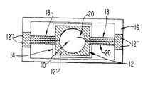
図1を参照して本発明の第1実施の形態を説明する。図1には、シリコン基板12上にマウントされた集積GaAlAs VCSELレーザダイオード10を含む本発明によるデバイス構造の平面図が示されている。そのデバイス及び基板は、ここではまとめて“レーザ装置14”として称することにする。そのレーザ装置14は小枠アッセンブリ16内に、一対のTiNiねじれヒンジ18で支持されている、そのヒンジ部はそれぞれ基板12と、小枠アッセンブリ16の対向する面に固着されている。
【0024】
電気接点20,20´は、それぞれのヒンジ18に沿って通っている。一方の接点20はVCSEL10に接続され、離れた電源から電力を供給する。
VCSEL10の活性領域は、そのより感応の低い表面によって十分に保護されており、VCSEL10を有する基板12をウエハー接合することが可能である。必要としない半導体エリア(SiとGaAlAsの両方)はその中央の島を定めるためエッチングして取り去ることができる。
【0025】
図1のデバイスは、いずれの側もねじれヒンジ(蝶番)で枠体中に釣り下げられているが、カンチレバー(片持梁)構造でなされても良い。デバイスを物理的に動かすためのアクチュエータ機構には、十分な動きが十分円滑で、しかも適当な方法で役割を分け与えられる静電気、バイメタル、形状記憶、圧電、磁気、あるいはその他のよく知られた形態でも良い。米国特許出願第08/141,342号には、いろいろ小型化された可動アッセンブリが図示されている。それは、もっと一般的で、ぴんと張ったバンド、マイラ、その他の運動基質上に載置することもできる。レンズは焦点合せのために、VCSELの頂部に備えられている。そのレンズは、干渉光学部品であり、VCSELに“ウエハー接合”することができる。
【0026】
図2を参照すると、バーコードリーダ31のハウジング29に配置された図1のレーザ装置14が示されており、そのVCSEL10は、デバイスの放射表面上に直接あるいは近接して載置されたレンズアレイ24によって平行にされる発散光ビームを生成する。拡散体26は、具体的には、VCSEL10が均一な照明を生成するために、平行光ビームの光路中で用いられる。拡散はどんな平行化をしなくても実行することができる。もし、光ビームの近くであれば、それは望ましく平行化されており、拡散しない。光ビームが拡散されているなら、その光ビームは目標の照明だけに用いられ、我々は、拡散のためCCDアレイを必要とする。
【0027】
平行化されているか拡散しているかのどちらかの光ビームは、スキャナ装置31のハウジング29にある窓27を通過して、バーコード符号を有する目標28に入射する。レーザ装置14は、バーコード符号を走査する静的な光ビームの線形運動を作り出すねじれヒンジ18のまわりに回転させられる。バーコード符号からの反射光は、光検知器30で検知され、検知された光の強度変化がデジタル化されて一般的なデコーダに適用される。レーザ装置14の典型的な動きは、走査するため約40度の角度で掃引する。
【0028】
バーコード符号のついた目標28を照明するためVCSEL10を用いることによって、照明光源の熱発生が従来技術のデバイスよりもかなり低く実現出来る。この場合、光ビームは走査されず、受光手段はCCDもしくはCMOSの検知器アレイであればよい。
バーコードリーダ31は、図2で固定装置として示されているが、他の実施の形態として、他のいろいろな形態をとり得る。例えば、図4に記載されているように、トリガで操作される銃タイプのような形態をとることもできる。
【0029】
図1に戻って、基板12の表面上に集積されたVCSEL10に加えて、“走査ミラー”の役割をする、ミラー12´と枠16の残りの部分は、光検知器センサ構成要素あるいはセンサアレイに形成することもできる。ミラー上の光検知器は、ミラーが常に走査ビームの方向に向きをかえることから、レトロ(再び元に帰る)反射型である。枠16上の検知器12″が固定されていれば、非レトロ反射型である。枠領域は、ミラーを支持するねじれヒンジの近くの空きスペースに占めることにより増やすことができる。
【0030】
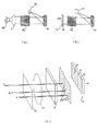
次に図3(a)、図3(b)、図3(c)を参照して、本発明の他の実施の形態を説明する。図3(a)では、VCSEL40から放射された光を平行光化し、合焦するための適当なレンズ41と、液晶アレイ42と共に、VCSELアレイ40の組み合わせを示している。一般によく知られている、例えば米国特許第5,071,229 号では、液晶、液晶ポリマー、PLZT等の開口サイズを変化させる光遮蔽手段のような電気光学効果を有する物質で構成される可変焦点距離レンズと、その光遮蔽手段の開口サイズの変化に同期して可変焦点距離レンズの焦点距離を変化させるための一般的な手段を示している。そうして、視野の明るさと、フォーカシングによる視野の深度と、目的物までの距離は、液晶デバイスで制御できることはよく知られている。液晶絞りのような電磁気的絞り装置が、液晶レンズのような可変焦点距離レンズと組合わせることによって、絞り直径を可変にできる結像レンズのフォーカス調整と連携するものとして、これまで従来技術として提案されてきた。電気光学的絞り装置の従来例としては特開昭59-156219 号公報に開示されている。
【0031】
本発明はまた、目標符号43上に一つの(走査)路を形成するため、所定のパターンでレンズ41から放射された光を指し向けるため、液晶アレイ42が有するシーケンシャルでかつ選択的に活性化され、独立の部品からなる手段でバーコード符号43の走査をするため、その液晶アレイ42を使用している。その符号43からの反射光は、公知のバーコード読み取りシステムではセンサ44により検知される。米国特許第5,258,605 号の、特にその中の図20を参照されたい。
【0032】
図3(b)に示される他の実施の形態では、バーコード符号43を照明するため、光源47を使用している。液晶アレイ42は、アレイ45上に結像される視野部分を選択し決定するように、視野を結像する検知器アレイ45と組み合わされて作用する。対応するフォーカスレンズアレイは、米国特許第5,345,336 号で図示されたアレイのように、検知器アレイ45中の特定の検知器要素が、特定の光学的特性(例えば、焦点距離、開口、偏光、フィルタリング等)のレンズ要素と組合わされるように、その検知器アレイ45と組合わされて用いられる。符号43がその検知器アレイ45から任意位置あるいは不知距離にある時とか、符号平面がアレイ面に対して歪んだ状態である時は、検知器要素とレンズ要素のマッチングが、検知器アレイ45上への符号43の正確な結像のために用いられるかもしれない。
【0033】
したがって、本実施の形態では、バーコードリーダからある距離を置いた符号を読み取るバーコードリーダを提供する。それは読み取り要素のグループの配列(アレイ)を含み、各グループは組み合わせにより所定の作動焦点距離を持っている。読み取り要素の各グループに対応した少なくとも一つの液晶要素があり、その選択可能な液晶要素の配列が読み取り要素の配列に隣接して配置される。対応する選択された液晶要素を通して、光を送る読み取り要素の対応したグループを選択するために選択液晶要素を活性するための手段を持ち、それによってリーダは所定の選択された作動焦点距離で作動することになる。
【0034】
図3(a),3(b)で示される液晶マトリックスの代用として、射出光ビームあるいは戻り光ビームの光路中に、小さい多数のミラーのアレイを用いてもよい。その様なミラーの選択的に活性化した個々の列(あるいはシーケンシャルなパターンにおけるそのようなミラーのうち所定の一つ)により、求める走査パターン(あるいは結像視野)のタイプにしたがって、特定の光源要素(光源のVCSELアレイのような)か、検知器要素(アレイ45のような)かのいずれかを“選択”できる。歪みミラーデバイス(以下“DMD”)は、テキサスインスツルメンツの“IBM,TIはマルチ光信号へのより良い道を表明”IEE協会1989年11月 VOL.13 NO.11の記事に示すように、液晶マトリックスに代わって、またはそれに加えて使用することができる。米国特許第5,256,269 号、第5,083,857 号および第4,441,791 号をも参照されたい。その様な先行技術に注目されるように、DMDは、電極のアレイ(チップ表面に位置し、それらの上にあるミラー画素要素を制御する)にアクセスするため、ダイナミックRAMのような同種のアドレス回路に依存する。DMDは、アナログとデジタルの両方の能力を持つ。アナログでの応用として、2つのアドレス電極のうち一方に電位をかけると、ミラー画素はある方向に回転され、その電圧を増加させると、ミラーの回転角度も増加する。本発明では、ある方向あるいは他の方向へフル回転するようにした。
【0035】
図3(c)は、図3(a)に示される実施の形態の他の実施の形態の拡大図である。図3(c)は、列と行32で並らび、そして一つの共通の基板34に配されたVCSEL10の二次元配列33を示す。レンズ35のアレイは、そのデバイスの出射光路中に同様に配列されている。レンズ35のアレイは、図3(c)のVCSEL10から離れて示されているが、それらは、図2のようにレーザビーム放射基板上に直接マウントされてもよい。半導体光源に密接、隣接して配置されたレンズアレイを用いている装置の一例が米国特許第5,345,336 号に開示されている。もう一つのレンズ36が、例えば異なった距離D1、D2、D3で各々独立の光ビームを合焦させるために、そのビーム光路中に配置されている。
【0036】
この実施の形態では、走査を行うデバイスの物理的な運動は何も記載していないが、他の実施の形態では、アレイが動く基板上に配置されることもあり得る。図3(c)では、走査の実行は、そのアレイの列のVCSEL10のシーケンシャルな励起によってなされる。このシーケンシャルな励起によって、バーコード37を検知器38が従来の方法でデコードできるように、反射光の強度変化をピックアップできるように、バーコードが掃引されることによって、単一走査ビームと等価の走査が作り出される。
【0037】
本発明は、VCSELデバイスの多様なタイプと一緒に実施され、それらは2−6族、またはより好ましくは特に3−5族の化合物半導体材料層を含むことが推奨される。ある実施の形態として、レンズ35の配列は一つの焦点面で単一走査ビームと同じ効果を提供するように配置される。しかしながら、このレンズ35の配列はまた、異なる面上へ焦点合わせされる一連のビームを形成するように設計されている。この場合、重要な焦点面は手動で選択されるか、もしくは、デコーダがうまくデコードされた情報の受領を認識するまで自動シーケンスの一部として繰り返される。そして、本発明ではリーダからある距離にある符合を読み取るための以下の構成からなるバーコードリーダをも提供する。
【0038】
読み取り要素のグループの配列と(その各々のグループは関連した所定の操作焦点距離を持っている)、
前記読み取り要素の配列に隣接しておかれており、少なくとも一つの液晶もしくはDMD要素が読みだし要素の各グループに対応している、選択可能な液晶の配列もしくはDMD要素と、
そして、対応し選択された要素を通過して光を伝送する(そこではリーダが所定の選択された操作焦点距離で操作される)ため読み出し要素の該当したグループを選択するために選択された液晶もしくはDMD要素を活性化するための手段とである。
【0039】
もちろん、本発明によれば、可視領域もしくは赤外線領域の波長で放射される光ビームでも同様によく作動できる。
例えば、CCDタイプのバーコードリーダでは、検知器の前に光学的バンドパスフィルタを採用することによって、検知器に到達する環境光を減らすことができる。フィルタと、レーザ(非常によい目標物照明になる)からの高パワー出力との結み合わせにより、そのような検知器の作動範囲をかなり増すことができる、そしてそれは結像タイプの検知器にとって特に重要である。図4には、本発明の集積された電気−光学デバイスを使ったバーコードリーダのあるタイプの最も簡略な実施の形態が図示されている。リーダ100は、図示したような手持ちスキャナとして使用されるか、固定スキャナのデスクトップのワークステーションとして使用される。好ましい実施の形態としては、光伝送窓(射出窓)156を通って外に向う光ビーム151がハウジング155の外に配置された符号170上に指し向けられ、横断して走査されるように、光伝送窓156を含むハウジング155に配置される。
【0040】
図4の手持ちデバイスは、米国特許第4,760,248 号(発明者Swartz等)あるいは、米国特許第4,896,026 号に開示されたタイプであり、そしてまたシンボルテクノロジ社の製品番号LS8100,LS2000,LS3000として市販のバーコードリーダの構成に似ている。それに代えて、もしくはそれに加えて、米国特許第4,387,297 号(発明者Swartz等)あるいは米国特許第4409470 号(発明者Shepard 等)の特徴は、図4のバーコードリーダユニットの構成を採用していることである。これらの米国特許第4,760,248 号、米国特許第4,896,026 号、米国特許第4,409,470 号は本明細書に先行技術として援用され、またそのようなデバイスの一般的なデザインは、参考のためここで簡単に説明する。
【0041】
図4を参照して、より詳細に説明すると、射出光ビーム151は、リーダ100の中で電気−光学デバイスによって生成され、リーダユニットの前方数インチのところの目標物上に置かれたバーコード符号に照射するべく指し向けられる。その射出光ビーム151は、走査パターンにしたがって走査される。そして使用者は手持ちユニットを、走査パターンが符号を横切って読み取られるように位置付けする。
【0042】
その符号からの反射及び/もしくは拡散された光152はリーダユニット内の光応答デバイス158によって検知され、バーコードによって表されたデータを再生するため処理され、デコードされて連続した電気信号を生成する。以下、用いられる文言“反射光(reflected light)”は、反射及び/もしくは拡散光を意味する。
【0043】
望ましい実施の形態においては、そのリーダユニット100は、グリップ部153のピストル型グリップを有するガン形状のデバイスである。可動トリガ154は、使用者が符号を指し示すためデバイスを位置づけしたとき、光ビーム151及び検知器回路を活性化するように作動される。軽量のプラスチック製ハウジング155は、レーザ光源146と、検知器158と、光学系157、147、159、および電源もしくはバッテリ162とともにCPU140を持つ符号処理回路とを含む。ハウジング155の前端部にある光伝送窓156は、光ビーム151が射出されるように、また反射光152が入ってくることができるようにする。リーダ100は、符号に触れないで、ある間隔で離れたバーコード符号を狙うことができ、あるいは符号を横切って動かすことができるように設計されている。典型的には、手持ちバーコードリーダのこのタイプは、おそらく数インチの範囲内で作動するように特定されている。
【0044】
既知の米国特許第4,409,470 号に開示されているように、リーダ100は、持ち運び可能なコンピュータ端末としての機能を持ち、キーボード148とディスプレイ149を含む。
本発明は、一次元もしくは二次元バーコードの読み取りに関して記述してきたが、そのような実施の形態に限られるものではなく、更に複雑な記号走査の応用に適用することもできる。本発明の方法は、種々のマシンビジョン(機械視覚)あるいは光学的キャラクタ認識応用(そこでは、情報は文字のような他のタイプの記号、あるいは走査する物品の表面特性から引き出される)と共に用いるための応用をも見つけだすことができると、考えられる。
【0045】
その種々の実施の形態の全てにおいて、本スキャナの要素は、全スキャナが集積モジュールの単一プリント回路基板として組み付けられるように、非常にコンパクトなパッケージの中に組み付けることが可能である。そのようなモジュールは、データ取得システムの様々な異なるタイプ用のレーザ走査要素として交換して用いることができる。例えば、そのモジュールは、手持ちスキャナに用いられたり、フレキシブルアームに取り付けられたり、テーブル上に伸びて据え付けられたり、テーブルトップの下面に取り付けられたり、もっと精巧なデータ取得システムの副構成要素あるいは副組立体として組み付けられたりするテーブルトップスキャナにおいて、選択的に用いられる。そのような構成要素につながった制御もしくはデータのラインは、そのモジュールの縁あるいは外部面に取り付けられた電気コネクタに接続されており、そのモジュールが他のデータ取り込システムの構成要素に取り付けられた接続コネクタに電気的に接続可能となる。
【0046】
各々のモジュールは、例えば、ある作動距離での作動や、特定の記号や印刷密度での作動と連動した特定の走査特性もしくはデコード特性を有する。その特性は、そのモジュールと連動した制御スイッチのマニュアル設定によって定義される。ユーザーは、異なるタイプの物品を走査するために、そのデータ取得システムを適用させることができるし、または、簡単な電気コネク
タを用いてデータ取得システムのモジュールを交換することによって、そのシステムは異なる装置に応用することもできる。
【0047】
上記の走査モジュールは、また、キーボード、ディスプレイ、プリンタ、データ記憶部、アプリケーションソフトウエア、データベースの一つ、もしくはそれ以上を含む自己内蔵のデータ取得システムに備えられることもできる。そのようなシステムはまた、データ取得システムが、モデムあるいはISDNインターフエースを通してばかりでなく、携帯ターミナルから定位置レシーバーへの低消費電力無線通信によってローカルエリアネットワークの他の構成要素と通信したり、あるいは、電話交換ネットワークと通信できるようにしたりできるような通信インターフエースを含むことができる。
【0048】
上記した特徴の各々、あるいは二つまたはそれ以上を一緒にすることによって、上述したタイプとは異なる他のスキャナやバーコードリーダにおいて有用な応用が見つかるであろうことは理解されよう。
本発明は具体的に図示し説明されてきたが、詳細に示されたものに限定されることを意味するものではない。種々の実施の形態および構造上の変形が、どんな形であれ、本発明の精神を外れないでなすことができるからである。
【0049】
さらに分析検討すること無しに、前述の内容によって十分本発明の要旨を開示しているので、他の人は、先行技術から、公正に本発明の一般的あるいは特定の観点から本質的な特性を構成する特徴を除外することなく容易にいろいろな装置に応用できる。従って、そのような応用は、特許請求の範囲と同等の意味の範囲内であると理解されるべきであり、また理解されるはずである。
【図面の簡単な説明】
【図1】 図1は、ねじれマイクロマシンミラー上に取り付けられたVCSELおよび検知器を正面から見た図である。
【図2】 図2は、本発明のバーコードスキャナの一実施の形態を示す図である。
【図3】 図3(a)乃至図3(c)は、本発明のバーコードスキャナの他の実施の形態を示す図である。
【図4】 図4は、本発明を用いた手持ち式バーコードスキャナである。
【符号の説明】
10 垂直共振型面発光レーザ(VCSEL)
12 シリコン基板
14 レーザ装置
16 枠
18 ヒンジ
20 電気接点
24 レンズアレイ
26 拡散体
27 窓
28 目標
29 ハウジング
30 光検知器
31 バーコードリーダ
34 基板
35 レンズ
36 レンズ
37 バーコード
38 検知器
40 レーザダイオード(VCSEL)
41 レンズ
42 液晶アレイ
43 目標符号
44 センサ
45 検知器アレイ
46 レンズアレイ
47 光源
100 バーコードリーダ
140 CPU
146 レーザ光源(VCSEL)
147 光学系
148 キーボード
149 ディスプレイ
151 射出光ビーム
152 反射光(分散光)
153 グリップ部
154 トリガ
155 ハウジング
156 出口
157 光学系
158 検知器
159 光学系
162 バッテリー
170 符号[0001]
BACKGROUND OF THE INVENTION
The present invention relates to an optical scanner for reading electro-optical reading marks having different light reflectivity parts, for example barcodes or codes in a matrix arrangement. In particular, it relates to a device employing a vertical cavity surface emitting laser (VCSEL) diode.
[0002]
[Problems to be solved by the invention]
Various optical scanners and optical scanning systems have been developed in the past to read marks such as barcode codes found on labels and product surfaces. The bar code code itself is a coded pattern of marks made up of a series of bars of varying widths connected to each other by spaces of varying widths, the bars and spaces having different light reflecting properties. . An optical scanner (reader) in a scanning system converts graphic marks into electrical signals electro-optically and decodes them into alphanumeric characters that can write an article or some characteristic. Such characteristics are typically provided in digital form and used as input to a data processing system for sales processing, inventory management, and other applications. This type of common scanning system has been previously disclosed, for example, in U.S. Pat. Nos. 4,251,798, 4,369,361, 4,287,297, 4,409,470, 4,760,248, 4,896,026. As disclosed in some of the above patents, an example of such a scanning system is shown as a handheld, portable laser scanning device, especially by a user, which is the device's scanning head on the target code to be read by the user. In particular, the light beam can be aimed.
[0003]
The light source of the laser scanning bar code reader is typically a gas laser or a semiconductor laser. The use of semiconductor devices as light sources is particularly desirable because they are small, low cost, and low voltage driven. The light beam is optically modified, typically by an optical assembly, to form a light spot of a size at a target distance. The cross-section of the light spot at the target distance is preferably approximately the same as the minimum width between regions of different light reflectivity, for example, bars and spaces with symbols. At least some barcode readers have been proposed with two light sources to generate two light beams of different frequencies.
[0004]
One laser barcode scanner shown in the present invention is disclosed in U.S. Pat. No. 5,144,120 by inventor Krichever et al., Which is a mirrorless scanner and employs a laser, optical system and sensor. . One or more of these components are mounted on a drive for reciprocal reciprocation on an axis or plane to make scanning effective.
[0005]
Other proposed bar code scanners use electrical means rather than mechanical devices to scan the bar code code with the light beam. A linear array of multiple light sources that are driven (activated) one at a time in a regular sequence can be imaged onto its barcode code to simulate the scanning beam. Instead of a single linear array of multiple light sources, a multi-line array can be used to create multi-scan lines. Such a scanner is disclosed in US Pat. No. 5,258,605 by Metlitsky et al.
[0006]
Typically, the semiconductor laser used in such a bar code scanner is an edge-emitting injection laser, the light beam coming from a pn junction region on the polished end face of the device. Radiated.
From the physical laws of nature, these well-known edge emitting injection lasers emit a beam from a thin region of a pn junction. In order to provide a given power output, there is only a small area where the heat generated must be dissipated. Furthermore, the light beam from a thin source has a large beam spread, which makes focusing difficult, and as a result, the function of the semiconductor laser varies greatly.
[0007]
Recently, there is a vertical-cavity surface-emitting laser (VCSEL) as a semiconductor laser that has been developed. It is published in IEE Photonics Technology Letters, Vol. 6, No. 3, March 1994 by RP Schneider et al. "Efficient Room-Temperature Continuous-Wave AlGaInP / AlGaAs Visible (670 nm) Vertical-Cavity Surface Emitting Laser Diodes". See U.S. Pat. Nos. 5,283,447, 5,285,466, 5,266,794, 5,319,496, and 5,326,386.
[0008]
The VCSEL has a surface area sufficient to emit a light beam. The primary divergence is much less than the well-known edge-emitting type semiconductor laser diode. The emitted light beam is round and substantially free of astigmatism. Furthermore, importantly, VCSELs typically drive at lower power than edge emitting semiconductor laser diodes. Therefore, less heat is generated.
[0009]
In well-known light beam scanning systems in the art, a single scanning light beam is directed by a lens or other optical component along an optical path directed to a target having a barcode code on its surface. A movable beam scanner repeatedly scans a light beam across a code in one scanning line or a series of scanning lines by means of driving a scanning component such as a light source itself or a mirror arranged in the optical path of the light beam. Operate by. The scanning component can sweep the light spot across the code, trace the scan pattern across the code pattern, scan the scanner field of view, or both.
[0010]
The bar code reader system also includes a sensor or photodetector that detects light reflected or scattered from the code. A photodetector or sensor is positioned within the scanner in the optical path to have a field of view that can reliably capture a portion of the light reflected or diverged from the code and detected and converted into an electrical signal. It is done. The electrical circuit and software decodes the electrical signal into a digital representation of the data indicated by the scanned code. For example, an analog electrical signal generated by a photodetector is converted into a pulse or modulated digital signal having a width corresponding to the physical width of a bar or space by a digitizer. Such a digital signal is then decoded into a binary representation of the data encoded in that code based on the symbolic symbology used, and then converted into alpha numeric characters representing it. .
[0011]
The decoding process of a well-known bar code reader system usually works as follows. The decoder receives a modulated pulse width of the digital signal from the digitizer, receives an algorithm provided in software, and attempts to decode the scan. If the scan has completely decoded the start and stop characters, and the characters between them, the decoding process ends and the reading success indicator (green light emission or warning sound) is displayed to the user. Indicated. Otherwise, the decoder will receive the next scan and the decoder will attempt other decodes of that scan until it is completely decoded or no longer valid for further scans. Such a signal is then decoded according to symbology into a binary representation of the data encoded in that code and into an alphanumeric character representing it.
[0012]
Portable optical scanners are not limited to the types of optical devices that can read barcode codes. Other types work with detectors based on solid state imaging arrays or charge imaging device (CCD) technology. In such prior art optical scanners, the detector side is usually smaller than the reading code because the image is reduced by a lens on the front of the array or CCD. The entire area of the code is viewed with light from a light source such as a light emitting diode (LED) of the scanning device, and each cell in the array is sequenced to determine the presence of bars and spaces in the field of view of the cell. Read out automatically.
[0013]
The operating range of CCD scanners is rather limited compared to laser-based scanners, especially for CCD-based barcodes with LED illumination sources. Other features of barcode scanners using CCDs are described in US Pat. No. 5,210,398. This prior art discloses use in a CCD type scanner for reading symbols of information arranged in a two-dimensional pattern.
[0014]
It is a general object of the present invention to provide an optical scanner for barcode reading provided on a semiconductor substrate.
Another object of the present invention is to load light illumination and sensing elements on a small frame assembly so that it can be moved to produce a scanning pattern.
Yet another object of the present invention is to provide a lens array and / or a liquid crystal shutter element array adjacent to a semiconductor substrate that includes an array of light illumination and / or sensing elements.
[0015]
Still another object of the present invention is to provide an optical scanner, such as a barcode reader, which uses a vertical cavity surface emitting laser diode as an illumination light source.
Yet another object of the present invention allows automatic adjustment (ie, eliminating the focus step in the manufacturing process) using a VCSEL array to achieve multiple in-focus.
[0016]
[Means for Solving the Problems]
In accordance with these and other objectives that will become apparent below, one feature of the present invention is that, briefly stated, different light reflectance portions (eg, bar code symbols with alternating bars and spaces). An integrated optical scanner for reading symbols having
[0017]
Another feature of the present invention is to illuminate the field of view including the symbol with a series of light spots by sequentially activating a plurality of light sources disposed on the semiconductor substrate, and the light reflected from the symbol. In order to generate an electric signal of reflected light having an intensity change, there is a method of reading a symbol such as a barcode code by detecting reflected light from the visual field.
[0018]
In addition, the present invention includes a light source component that emits one or more light beams, a light directing component that directs the light beam along the optical path toward the symbol, and a field of view that reflects from the symbol. A bar code reader for reading symbols is provided comprising a fixed photodetector component that serves to detect at least a portion of reflected light having a change in light intensity. An optical arrangement is provided that functions to scan different focal planes located outside the barcode reader and provide a series of independent scans for the symbols.
[0019]
In the present invention, a vertical cavity surface emitting laser (VCSEL) placed on a substrate and arranged to generate a multi-laser beam output, a scanning arrangement that effectively scans with a light beam, and reflection from a target An optical scanner having a configuration for detecting light is provided.
The surface area of the VCSEL is usefully used to support optical components (eg, interference or refractive lenses) directly on the front surface of the diode. Implementation of optical components can be conveniently done during assembly to achieve the desired focus. The VCSEL is used only for concentrated irradiation for a short time in the use of the scanner, and can further reduce the power consumption of the VCSEL. As a result, the VCSEL substrate could provide sufficient heat dissipation without the need for further laser heat sinks.
[0020]
As a particular form of the invention, a phased array of lasers can place focused scanning beams at different positions in defined groups. Instead, the scanning can be done electrically by actuating a stepped array of laser diodes to produce the effect of a single scanning beam. These operate selectively or according to a predetermined automatic sequence. Thus, if such a system is desired, multiple line scans can be created, or two or more laser light beams can create a predetermined shaped light spot on a predetermined target surface. Developed.
[0021]
Scanning can also be caused by physically moving the laser at region points or multiple points. Therefore, in both cases, especially in the case of laser stepping, there is an advantage over the prior art devices at the low power consumption by the VCSEL.
[0022]
DETAILED DESCRIPTION OF THE INVENTION
The term “symbol” used in this specification and claims should be interpreted in a broad sense, not just a code pattern with alternating bars and spaces, but other patterns, alphanumeric characters. It covers any code that consists of parts with different light reflectivity, such as letters.
[0023]
A first embodiment of the present invention will be described with reference to FIG. FIG. 1 shows a plan view of a device structure according to the present invention including an integrated GaAlAs VCSEL laser diode 10 mounted on a
[0024]
The
The active region of the VCSEL 10 is well protected by its less sensitive surface, and the
[0025]
The device of FIG. 1 is suspended in the frame by a torsional hinge (hinge) on either side, but may be made in a cantilever (cantilever) structure. Actuator mechanisms for physically moving the device can be static, bimetallic, shape memory, piezoelectric, magnetic, or other well-known forms that are sufficiently smooth to move and can be assigned roles in an appropriate manner. good. US patent application Ser. No. 08 / 141,342 shows a variety of miniaturized movable assemblies. It is more general and can be placed on a taut band, mylar, or other motion substrate. A lens is provided on top of the VCSEL for focusing. The lens is an interference optical component and can be “wafer bonded” to the VCSEL.
[0026]
Referring to FIG. 2, there is shown the
[0027]
Either the collimated or diffused light beam passes through a
[0028]
By using the VCSEL 10 to illuminate the
Although the
[0029]
Returning to FIG. 1, in addition to the VCSEL 10 integrated on the surface of the
[0030]
Next, another embodiment of the present invention will be described with reference to FIGS. 3 (a), 3 (b), and 3 (c). FIG. 3A shows a combination of the
[0031]
The present invention also sequentially and selectively activates the
[0032]
In another embodiment shown in FIG. 3 (b), a
[0033]
Therefore, in this embodiment, a bar code reader that reads a code at a certain distance from the bar code reader is provided. It contains an array of groups of read elements, each group having a predetermined working focal length in combination. There is at least one liquid crystal element corresponding to each group of read elements, and an array of selectable liquid crystal elements is disposed adjacent to the array of read elements. Has means for activating the selected liquid crystal element to select a corresponding group of reading elements that transmit light through the corresponding selected liquid crystal element, whereby the reader operates at a predetermined selected operating focal length It will be.
[0034]
As an alternative to the liquid crystal matrix shown in FIGS. 3 (a) and 3 (b), an array of a large number of small mirrors may be used in the optical path of the exit light beam or the return light beam. A specific light source according to the type of scanning pattern (or imaging field) sought by selectively activated individual rows of such mirrors (or a predetermined one of such mirrors in a sequential pattern). Either an element (such as a VCSEL array of light sources) or a detector element (such as array 45) can be “selected”. The distortion mirror device (hereinafter “DMD”) is a Texas Instruments “IBM, TI Announces Better Way to Multi-Optical Signals”, November 1989, Vol. 13 NO. As shown in 11 articles, it can be used instead of or in addition to a liquid crystal matrix. See also U.S. Pat. Nos. 5,256,269, 5,083,857 and 4,441,791. As noted in such prior art, the DMD accesses the array of electrodes (located on the chip surface and controls the mirror pixel elements above them) so that the same type of address as dynamic RAM. Depends on the circuit. DMD has both analog and digital capabilities. As an analog application, when a potential is applied to one of the two address electrodes, the mirror pixel is rotated in a certain direction, and when the voltage is increased, the rotation angle of the mirror is also increased. In the present invention, a full rotation is made in one direction or the other direction.
[0035]
FIG. 3 (c) is an enlarged view of another embodiment shown in FIG. 3 (a). FIG. 3 (c) shows a two-dimensional array 33 of VCSELs 10 arranged in columns and rows 32 and arranged on one
[0036]
This embodiment does not describe any physical movement of the device that performs the scan, but in other embodiments the array may be placed on a moving substrate. In FIG. 3 (c), the scan is performed by sequential excitation of the VCSEL 10 in the array column. With this sequential excitation, the bar code is swept so that it can pick up the intensity change of the reflected light so that the detector can be decoded in a conventional manner, so that the equivalent of a single scanning beam is obtained. A scan is created.
[0037]
The present invention is practiced with various types of VCSEL devices, which are recommended to include compound semiconductor material layers of Group 2-6, or more preferably Group 3-5. In one embodiment, the array of
[0038]
An array of groups of reading elements, each of which has a predetermined operating focal length associated with it,
A selectable liquid crystal array or DMD element adjacent to the array of read elements, wherein at least one liquid crystal or DMD element corresponds to each group of read elements;
And a liquid crystal selected to select a corresponding group of readout elements for transmitting light through the corresponding selected element (where the reader is operated at a predetermined selected operating focal length). Or a means for activating the DMD element.
[0039]
Of course, according to the present invention, a light beam radiated at a wavelength in the visible region or in the infrared region can be similarly operated.
For example, in a CCD type barcode reader, ambient light reaching the detector can be reduced by employing an optical bandpass filter in front of the detector. The combination of the filter and the high power output from the laser (which results in a very good target illumination) can significantly increase the operating range of such a detector, which is useful for imaging type detectors. Of particular importance. FIG. 4 illustrates one type of simplest embodiment of a bar code reader using the integrated electro-optic device of the present invention. The
[0040]
The hand-held device of FIG. 4 is of the type disclosed in US Pat. No. 4,760,248 (inventor Swartz et al.) Or US Pat. Similar to code reader configuration. Alternatively or in addition, US Pat. No. 4,387,297 (inventor Swartz et al.) Or US Pat. No. 4,409,470 (inventor Shepard et al.) Employs the bar code reader unit configuration of FIG. That is. These U.S. Pat.No. 4,760,248, U.S. Pat.No. 4,896,026, U.S. Pat.No. 4,409,470 are incorporated herein by reference and the general design of such devices is briefly described here for reference. To do.
[0041]
Referring to FIG. 4, in more detail, the emitted
[0042]
Reflected and / or diffused light 152 from the code is detected by an
[0043]
In the preferred embodiment, the
[0044]
As disclosed in known US Pat. No. 4,409,470, the
Although the present invention has been described with respect to reading one-dimensional or two-dimensional barcodes, it is not limited to such an embodiment, and can be applied to more complex symbol scanning applications. The method of the present invention is for use with a variety of machine vision or optical character recognition applications where information is derived from other types of symbols, such as letters, or surface characteristics of the article being scanned. It is thought that the application of can be found.
[0045]
In all of its various embodiments, the elements of the scanner can be assembled in a very compact package so that the entire scanner can be assembled as a single printed circuit board of an integrated module. Such a module can be used interchangeably as a laser scanning element for various different types of data acquisition systems. For example, the module can be used in hand-held scanners, attached to flexible arms, stretched and mounted on a table, attached to the underside of a table top, or subcomponents or subcomponents of more sophisticated data acquisition systems. It is selectively used in a table top scanner that is assembled as an assembly. The control or data line leading to such a component is connected to an electrical connector attached to the edge or external surface of the module, and the module is attached to another data acquisition system component It can be electrically connected to the connection connector.
[0046]
Each module has specific scan or decode characteristics that are linked to, for example, operation at a certain working distance or operation at a specific symbol or print density. Its characteristics are defined by the manual setting of the control switch linked to the module. The user can apply the data acquisition system to scan different types of articles, or a simple electrical connector.
By exchanging the modules of the data acquisition system using the data, the system can also be applied to different devices.
[0047]
The above scanning module can also be provided in a self-contained data acquisition system including one or more of a keyboard, display, printer, data storage, application software, database. Such a system also allows the data acquisition system to communicate with other components of the local area network not only through a modem or ISDN interface, but also through low power wireless communication from the mobile terminal to the home position receiver, or A communication interface capable of enabling communication with a telephone exchange network.
[0048]
It will be appreciated that by combining each of the above features, or two or more, useful applications may be found in other scanners and bar code readers different from the types described above.
Although the invention has been particularly shown and described, it is not meant to be limited to the details shown. This is because various embodiments and structural modifications can be made in any form without departing from the spirit of the present invention.
[0049]
The subject matter of the present invention has been sufficiently disclosed by the above contents without further analysis and examination, so that others have obtained essential characteristics from the prior art from a general or specific point of view of the present invention. It can be easily applied to various devices without excluding the constituent features. Accordingly, such an application should be understood and understood to be within the scope of meaning equivalent to the claims.
[Brief description of the drawings]
FIG. 1 is a front view of a VCSEL and detector mounted on a twisted micromachine mirror.
FIG. 2 is a diagram showing an embodiment of a barcode scanner according to the present invention.
3 (a) to 3 (c) are diagrams showing another embodiment of the barcode scanner of the present invention.
FIG. 4 is a hand-held bar code scanner using the present invention.
[Explanation of symbols]
10 Vertical cavity surface emitting laser (VCSEL)
12 Silicon substrate
14 Laser equipment
16 frames
18 Hinge
20 Electrical contacts
24 Lens array
26 Diffuser
27 windows
28 goals
29 Housing
30 Light detector
31 Bar code reader
34 Substrate
35 lenses
36 lenses
37 Barcode
38 Detector
40 Laser diode (VCSEL)
41 lens
42 Liquid crystal array
43 Target code
44 sensors
45 Detector array
46 Lens array
47 Light source
100 Bar code reader
140 CPU
146 Laser light source (VCSEL)
147 Optical system
148 keyboard
149 display
151 Emission light beam
152 Reflected light (dispersed light)
153 Grip part
154 trigger
155 housing
156 Exit
157 optical system
158 detector
159 Optical system
162 battery
170 code
Claims (1)
各々のグループが関連する所定の作動焦点距離を持つ、読み取り要素の複数のグループの配列(アレイ)と、An array of arrays of read elements, each group having a predetermined working focal length associated with it;
前記読み取り要素に隣接して配置され、少なくともその一つの液晶素子が読み取り要素の各グループに対応している選択可能な液晶素子の配列(アレイ)と、An array of selectable liquid crystal elements arranged adjacent to the read element, at least one of which is associated with each group of read elements;
前記光学スキャナが所定の選択された作動焦点距離で作動するところで対応する選択された要素を通して光を伝達するための対応する読み取り要素のグループを選択できるように、選択された液晶素子を活性化する手段と、から成ることを特徴とする光学スキャナ。Activating the selected liquid crystal element so that a corresponding group of reading elements can be selected for transmitting light through the corresponding selected element where the optical scanner operates at a predetermined selected operating focal length. And an optical scanner.
Applications Claiming Priority (2)
| Application Number | Priority Date | Filing Date | Title |
|---|---|---|---|
| US39481395A | 1995-02-27 | 1995-02-27 | |
| US08/394813 | 1995-02-27 |
Publications (2)
| Publication Number | Publication Date |
|---|---|
| JPH0950476A JPH0950476A (en) | 1997-02-18 |
| JP3698794B2 true JP3698794B2 (en) | 2005-09-21 |
Family
ID=23560523
Family Applications (1)
| Application Number | Title | Priority Date | Filing Date |
|---|---|---|---|
| JP03922796A Expired - Fee Related JP3698794B2 (en) | 1995-02-27 | 1996-02-27 | Optical scanner |
Country Status (4)
| Country | Link |
|---|---|
| US (2) | US6062476A (en) |
| EP (1) | EP0731417B1 (en) |
| JP (1) | JP3698794B2 (en) |
| DE (1) | DE69632882T2 (en) |
Families Citing this family (70)
| Publication number | Priority date | Publication date | Assignee | Title |
|---|---|---|---|---|
| US6736321B2 (en) | 1995-12-18 | 2004-05-18 | Metrologic Instruments, Inc. | Planar laser illumination and imaging (PLIIM) system employing wavefront control methods for reducing the power of speckle-pattern noise digital images acquired by said system |
| US6742709B2 (en) | 1990-09-11 | 2004-06-01 | Metrologic Instruments, Inc. | Bar code symbol reading system employing electronically-controlled raster-type laser scanner for reading bar code symbols during hands-on and hands-free modes of operation |
| US7428995B1 (en) * | 1993-10-25 | 2008-09-30 | Symbol Technologies, Inc. | Scanning devices and methods using surface emitting laser diodes |
| US6547144B1 (en) | 1994-08-17 | 2003-04-15 | Metrologic Instruments, Inc. | Holographic laser scanning system for carrying out light collection operations with improved light collection efficiency |
| US6073846A (en) * | 1994-08-17 | 2000-06-13 | Metrologic Instruments, Inc. | Holographic laser scanning system and process and apparatus and method |
| US6006993A (en) * | 1994-08-17 | 1999-12-28 | Metrologic Instruments, Inc. | Holographic laser scanning system for carrying out laser beam scanning operations with improved scan angle multiplication efficiency and carrying out light collection operations with improved light collection efficiency |
| US6003772A (en) * | 1994-08-17 | 1999-12-21 | Metrologic Instruments, Inc. | Holographic laser scanning system employing holographic scanning disc having dual-fringe contrast regions for optimized laser beam scanning and light collection operations |
| US6085978A (en) * | 1994-08-17 | 2000-07-11 | Metrologic Instruments, Inc. | Holographic laser scanners of modular construction and method and apparatus for designing and manufacturing the same |
| US6158659A (en) * | 1994-08-17 | 2000-12-12 | Metrologic Instruments, Inc. | Holographic laser scanning system having multiple laser scanning stations for producing a 3-D scanning volume substantially free of spatially and temporally coincident scanning planes |
| US6199759B1 (en) | 1994-08-17 | 2001-03-13 | Metrologic Instruments, Inc. | Bar code symbol scanning system having a holographic laser scanning disc utilizing maximum light collection surface area thereof and having scanning facets with optimized light collection efficiency |
| US6619550B1 (en) | 1995-12-18 | 2003-09-16 | Metrologic Instruments, Inc. | Automated tunnel-type laser scanning system employing corner-projected orthogonal laser scanning patterns for enhanced reading of ladder and picket fence oriented bar codes on packages moving therethrough |
| US8153957B2 (en) | 1996-09-27 | 2012-04-10 | Digitaloptics Corporation East | Integrated optical imaging systems including an interior space between opposing substrates and associated methods |
| US6096155A (en) * | 1996-09-27 | 2000-08-01 | Digital Optics Corporation | Method of dicing wafer level integrated multiple optical elements |
| US6235141B1 (en) | 1996-09-27 | 2001-05-22 | Digital Optics Corporation | Method of mass producing and packaging integrated optical subsystems |
| US6162590A (en) * | 1997-04-11 | 2000-12-19 | Aerial Imaging Corporation | Method for making an optical or magneto-optic head and the resulting head |
| US7124950B2 (en) | 1997-09-16 | 2006-10-24 | Metrologic Instruments, Inc. | Bar code symbol reading system employing electronically-controlled raster-type laser scanner for reading bar code symbols during on hands-on and hands-free modes of operation |
| US7028899B2 (en) * | 1999-06-07 | 2006-04-18 | Metrologic Instruments, Inc. | Method of speckle-noise pattern reduction and apparatus therefore based on reducing the temporal-coherence of the planar laser illumination beam before it illuminates the target object by applying temporal phase modulation techniques during the transmission of the plib towards the target |
| TW582549U (en) * | 1997-09-24 | 2004-04-01 | Matsushita Electric Ind Co Ltd | Calculating apparatus of diffraction efficiency of diffraction lens, lens with optical grating device and reading optical system |
| US6669803B1 (en) | 1997-10-03 | 2003-12-30 | Digital Optics Corp. | Simultaneous provision of controlled height bonding material at a wafer level and associated structures |
| JP3823487B2 (en) * | 1997-10-27 | 2006-09-20 | 株式会社デンソー | Optical information reader |
| US6318635B1 (en) * | 1997-12-02 | 2001-11-20 | Telxon Corporation | Multi-focal length imaging based portable dataform reader |
| US7673803B2 (en) * | 1998-03-24 | 2010-03-09 | Metrologic Instruments, Inc. | Planar laser illumination and imaging (PLIIM) based engine |
| US6097528A (en) * | 1998-07-20 | 2000-08-01 | Motorola, Inc. | Microscanner for portable laser diode displays |
| US6091537A (en) * | 1998-12-11 | 2000-07-18 | Xerox Corporation | Electro-actuated microlens assemblies |
| US6959870B2 (en) * | 1999-06-07 | 2005-11-01 | Metrologic Instruments, Inc. | Planar LED-based illumination array (PLIA) chips |
| US6250550B1 (en) * | 1999-06-14 | 2001-06-26 | International Business Machines Corporation | Automated media storage library with variable focal length lens |
| US6315423B1 (en) * | 1999-07-13 | 2001-11-13 | Input/Output, Inc. | Micro machined mirror |
| US20020001089A1 (en) * | 2000-04-18 | 2002-01-03 | Price Jeffrey H. | Multiparallel three dimensional optical microscopy system |
| US6616046B1 (en) * | 2000-05-10 | 2003-09-09 | Symbol Technologies, Inc. | Techniques for miniaturizing bar code scanners including spiral springs and speckle noise reduction |
| KR100708081B1 (en) * | 2000-05-18 | 2007-04-16 | 삼성전자주식회사 | Apparatus and method for manufacturing oxide aperture of VCSEL |
| US6712273B1 (en) | 2000-08-22 | 2004-03-30 | Honeywell International Inc. | Versatile method and system for VCSEL-based bar code scanner |
| US6501530B2 (en) * | 2000-10-19 | 2002-12-31 | Eastman Kodak Company | Motion picture film projector illumination system for minimizing film buckle |
| US20020050519A1 (en) | 2000-10-26 | 2002-05-02 | Oliva Guido M. | Laser module for reading optical codes |
| EP2093694B1 (en) * | 2000-10-26 | 2011-06-22 | Datalogic S.p.A. | Receiving chamber for a laser reader |
| ATE300794T1 (en) * | 2000-10-26 | 2005-08-15 | Datalogic Spa | OPTICAL DEVICE FOR EMITTING/DETECTING A LIGHT SIGNAL AND PROTECTIVE/INSULATION HOUSING FOR A LIGHT SOURCE |
| US7954719B2 (en) * | 2000-11-24 | 2011-06-07 | Metrologic Instruments, Inc. | Tunnel-type digital imaging-based self-checkout system for use in retail point-of-sale environments |
| US7128266B2 (en) * | 2003-11-13 | 2006-10-31 | Metrologic Instruments. Inc. | Hand-supportable digital imaging-based bar code symbol reader supporting narrow-area and wide-area modes of illumination and image capture |
| US6556349B2 (en) | 2000-12-27 | 2003-04-29 | Honeywell International Inc. | Variable focal length micro lens array field curvature corrector |
| US6909554B2 (en) | 2000-12-27 | 2005-06-21 | Finisar Corporation | Wafer integration of micro-optics |
| US6567166B2 (en) * | 2001-02-21 | 2003-05-20 | Honeywell International Inc. | Focused laser light turbidity sensor |
| US7017815B2 (en) | 2001-05-01 | 2006-03-28 | Symbol Technologies, Inc. | Compact externally-driven scanner |
| US7513428B2 (en) * | 2001-11-21 | 2009-04-07 | Metrologic Instruments, Inc. | Planar laser illumination and imaging device employing laser current modulation to generate spectral components and reduce temporal coherence of laser beam, so as to achieve a reduction in speckle-pattern noise during time-averaged detection of images of objects illuminated thereby during imaging operations |
| US6789737B2 (en) * | 2001-12-19 | 2004-09-14 | Riotec Corp. | Light source mechanism of barcode scanner |
| JP2004133733A (en) * | 2002-10-11 | 2004-04-30 | Sony Corp | Display device, display method, and program |
| US6909080B2 (en) * | 2002-12-17 | 2005-06-21 | Symbol Technologies, Inc. | Arrangement for and method of imaging targets at plural focal planes |
| US7021542B2 (en) * | 2003-08-01 | 2006-04-04 | Symbol Technologies, Inc. | Imaging and illumination engine for an optical code reader |
| US7044377B2 (en) * | 2003-08-01 | 2006-05-16 | Symbol Technologies Inc. | Plug-and-play imaging and illumination engine for an optical code reader |
| US7148078B2 (en) * | 2004-02-23 | 2006-12-12 | Avago Technologies Egbu Ip (Singapore) Pte. Ltd. | Integrated circuit package provided with cooperatively arranged illumination and sensing capabilities |
| DE102006024313A1 (en) * | 2006-05-24 | 2007-11-29 | Diehl Bgt Defence Gmbh & Co. Kg | Microscopic positioning frame for infrared detector used in e.g. weapon system or search and rescue system |
| US7380721B2 (en) * | 2006-08-22 | 2008-06-03 | Honeywell International Inc. | Low-cost compact bar code sensor |
| JP2008191537A (en) * | 2007-02-07 | 2008-08-21 | Canon Inc | Vibrating element and light deflector equipped with the same |
| US8226009B2 (en) * | 2009-04-29 | 2012-07-24 | Hand Held Products, Inc. | Laser scanner with improved decoding |
| US8305691B2 (en) * | 2009-04-29 | 2012-11-06 | Hand Held Products, Inc. | Fluid lens element for use in changing thermal operating environment |
| US8282004B2 (en) * | 2009-04-29 | 2012-10-09 | Hand Held Products, Inc. | Focusing apparatus and terminal comprising variable focus lens assembly |
| US8038066B2 (en) * | 2009-04-29 | 2011-10-18 | Hand Held Products, Inc. | Laser scanner with deformable lens |
| US8678285B2 (en) * | 2011-09-20 | 2014-03-25 | Metrologic Instruments, Inc. | Method of and apparatus for multiplying raster scanning lines by modulating a multi-cavity laser diode |
| US9147096B2 (en) | 2012-11-13 | 2015-09-29 | Hand Held Products, Inc. | Imaging apparatus having lens element |
| EP2860553B1 (en) * | 2013-10-10 | 2015-12-30 | Sick Ag | Optoelectronic sensor and method for detecting object information |
| FR3025913B1 (en) * | 2014-09-12 | 2016-09-09 | Biomerieux Sa | BAR CODE READING DEVICE AND MACHINE FOR AUTOMATED ANALYSIS OF A SAMPLE COMPRISING SUCH A DEVICE |
| CA2892952C (en) | 2015-01-19 | 2019-10-15 | Tetra Tech, Inc. | Protective shroud |
| US9849895B2 (en) | 2015-01-19 | 2017-12-26 | Tetra Tech, Inc. | Sensor synchronization apparatus and method |
| US9618335B2 (en) | 2015-01-19 | 2017-04-11 | Tetra Tech, Inc. | Light emission power control apparatus and method |
| US10349491B2 (en) | 2015-01-19 | 2019-07-09 | Tetra Tech, Inc. | Light emission power control apparatus and method |
| US10362293B2 (en) | 2015-02-20 | 2019-07-23 | Tetra Tech, Inc. | 3D track assessment system and method |
| DE202017105001U1 (en) * | 2017-08-21 | 2017-09-14 | Jenoptik Advanced Systems Gmbh | LIDAR scanner with MEMS mirror and at least two scan angle ranges |
| US10807623B2 (en) | 2018-06-01 | 2020-10-20 | Tetra Tech, Inc. | Apparatus and method for gathering data from sensors oriented at an oblique angle relative to a railway track |
| US10625760B2 (en) | 2018-06-01 | 2020-04-21 | Tetra Tech, Inc. | Apparatus and method for calculating wooden crosstie plate cut measurements and rail seat abrasion measurements based on rail head height |
| US11377130B2 (en) | 2018-06-01 | 2022-07-05 | Tetra Tech, Inc. | Autonomous track assessment system |
| US10730538B2 (en) | 2018-06-01 | 2020-08-04 | Tetra Tech, Inc. | Apparatus and method for calculating plate cut and rail seat abrasion based on measurements only of rail head elevation and crosstie surface elevation |
| WO2020232443A1 (en) | 2019-05-16 | 2020-11-19 | Tetra Tech, Inc. | Autonomous track assessment system |
Family Cites Families (45)
| Publication number | Priority date | Publication date | Assignee | Title |
|---|---|---|---|---|
| US3986022A (en) * | 1973-06-04 | 1976-10-12 | Gilbert Peter Hyatt | Illumination control system |
| US4342906A (en) * | 1973-06-04 | 1982-08-03 | Hyatt Gilbert P | Pulse width modulated feedback arrangement for illumination control |
| US4251798A (en) * | 1978-05-31 | 1981-02-17 | Symbol Technologies | Portable laser scanning arrangement for and method of evaluating and validating bar code symbols |
| US4387297B1 (en) * | 1980-02-29 | 1995-09-12 | Symbol Technologies Inc | Portable laser scanning system and scanning methods |
| US4369361A (en) * | 1980-03-25 | 1983-01-18 | Symbol Technologies, Inc. | Portable, stand-alone, desk-top laser scanning workstation for intelligent data acquisition terminal and method of scanning |
| US4441791A (en) * | 1980-09-02 | 1984-04-10 | Texas Instruments Incorporated | Deformable mirror light modulator |
| US4409470A (en) * | 1982-01-25 | 1983-10-11 | Symbol Technologies, Inc. | Narrow-bodied, single-and twin-windowed portable laser scanning head for reading bar code symbols |
| JPS59156219A (en) * | 1983-02-28 | 1984-09-05 | 株式会社クボタ | Cane sugar harvester |
| DE3686494T2 (en) * | 1985-02-28 | 1993-04-01 | Symbol Technologies Inc | PORTABLE SCAN HEAD WITH LASER DIODE. |
| US5308966A (en) * | 1986-08-08 | 1994-05-03 | Norand Corporation | Hand-held instant bar code reader having automatic focus control for operation over a range of distances |
| JPS63184178A (en) * | 1986-10-14 | 1988-07-29 | Nippon Sci Kk | Crystal bar code reader |
| US4818886A (en) * | 1986-11-12 | 1989-04-04 | Quential, Inc. | Method and apparatus for self-referencing and self-focusing a bar-code reader |
| JPS63198177A (en) * | 1987-02-13 | 1988-08-16 | Matsushita Electric Ind Co Ltd | Optical reader |
| US4813762A (en) * | 1988-02-11 | 1989-03-21 | Massachusetts Institute Of Technology | Coherent beam combining of lasers using microlenses and diffractive coupling |
| US5144120A (en) * | 1988-05-11 | 1992-09-01 | Symbol Technologies, Inc. | Mirrorless scanners with movable laser, optical and sensor components |
| US5071229A (en) * | 1988-08-08 | 1991-12-10 | Olympus Optical Co., Ltd. | Imaging apparatus having electrooptic devices which comprise a variable focal length lens |
| US4896026A (en) * | 1988-10-31 | 1990-01-23 | Symbol Technologies, Inc. | Laser diode scanner with improved shock mounting |
| US5010241A (en) * | 1989-01-12 | 1991-04-23 | Hewlett-Packard Company | Sensor array and illumination system for a large depth-of-field bar code scanner |
| US4963756A (en) * | 1989-10-13 | 1990-10-16 | Hewlett-Packard Company | Focused line identifier for a bar code reader |
| US5148322A (en) * | 1989-11-09 | 1992-09-15 | Omron Tateisi Electronics Co. | Micro aspherical lens and fabricating method therefor and optical device |
| US5258605A (en) * | 1990-03-13 | 1993-11-02 | Symbol Technologies, Inc. | Scan generators for bar code reader using linear array of lasers |
| CA2021519C (en) * | 1990-05-29 | 2001-09-04 | Jerome Swartz | Scanning system implemented on semiconductor or electro-optical substrate |
| JP2740687B2 (en) * | 1990-06-08 | 1998-04-15 | 株式会社日本自動車部品総合研究所 | Optical scanning device |
| US5083857A (en) * | 1990-06-29 | 1992-01-28 | Texas Instruments Incorporated | Multi-level deformable mirror device |
| CA2032255A1 (en) * | 1990-12-14 | 1992-06-15 | Otto Sova | Method and apparatus for separating biological substances and organic compounds in solution |
| US5266787A (en) * | 1991-01-11 | 1993-11-30 | Symbol Technologies, Inc. | Laser scanner using two scan motors independently controlled by a single signal |
| US5210398A (en) * | 1991-06-14 | 1993-05-11 | Symbol Technologies, Inc. | Optical scanner with extended depth of focus |
| DE69221443T2 (en) * | 1991-12-09 | 1998-02-05 | Sharp Kk | Liquid crystal light valve and information processor using the same |
| US5283447A (en) * | 1992-01-21 | 1994-02-01 | Bandgap Technology Corporation | Integration of transistors with vertical cavity surface emitting lasers |
| US5266794A (en) * | 1992-01-21 | 1993-11-30 | Bandgap Technology Corporation | Vertical-cavity surface emitting laser optical interconnect technology |
| US5777314A (en) * | 1992-02-27 | 1998-07-07 | Symbol | Optical scanner with fixed focus optics |
| US5359669A (en) * | 1992-04-13 | 1994-10-25 | Motorola, Inc. | Remote retinal scan identifier |
| US5285466A (en) * | 1992-05-20 | 1994-02-08 | Wisconsin Alumni Research Foundation | Feedback mechanism for vertical cavity surface emitting lasers |
| US5350909A (en) * | 1992-10-14 | 1994-09-27 | International Business Machines Corp. | Optical scanner for bar code scanning |
| US5319496A (en) * | 1992-11-18 | 1994-06-07 | Photonics Research Incorporated | Optical beam delivery system |
| US5315095A (en) * | 1993-02-18 | 1994-05-24 | Symbol Technologies, Inc. | Beam with extended confinement for scanning purposes |
| WO1994019765A1 (en) * | 1993-02-19 | 1994-09-01 | Norand Corporation | Phased array laser scanner |
| US5326386A (en) * | 1993-04-09 | 1994-07-05 | Grumman Aerospace Corporation | Hydraulic reservoir with gas/oil separator |
| JPH06333074A (en) * | 1993-05-25 | 1994-12-02 | Nippondenso Co Ltd | Optical information reader |
| US5500540A (en) * | 1994-04-15 | 1996-03-19 | Photonics Research Incorporated | Wafer scale optoelectronic package |
| US5525810A (en) * | 1994-05-09 | 1996-06-11 | Vixel Corporation | Self calibrating solid state scanner |
| US5530233A (en) * | 1994-06-30 | 1996-06-25 | Symbol Technologies, Inc. | Bar code scanner with quasi-retroreflective light collection |
| US5745152A (en) * | 1994-10-31 | 1998-04-28 | Hewlett Packard Company | Multiple beam laser scanner using lasers with different aperture sizes |
| US5770847A (en) * | 1994-12-23 | 1998-06-23 | Spectra-Physics Scanning Systems, Inc. | Bar code reader with multi-focus lens |
| US5814827A (en) * | 1995-05-19 | 1998-09-29 | Symbol Technologies, Inc. | Optical scanner with extended depth of focus |
-
1996
- 1996-02-27 JP JP03922796A patent/JP3698794B2/en not_active Expired - Fee Related
- 1996-02-27 EP EP96301314A patent/EP0731417B1/en not_active Expired - Lifetime
- 1996-02-27 DE DE69632882T patent/DE69632882T2/en not_active Expired - Lifetime
-
1997
- 1997-03-21 US US08/828,275 patent/US6062476A/en not_active Expired - Fee Related
- 1997-09-17 US US08/999,956 patent/US6024283A/en not_active Expired - Fee Related
Also Published As
| Publication number | Publication date |
|---|---|
| DE69632882D1 (en) | 2004-08-19 |
| EP0731417A2 (en) | 1996-09-11 |
| US6024283A (en) | 2000-02-15 |
| JPH0950476A (en) | 1997-02-18 |
| US6062476A (en) | 2000-05-16 |
| DE69632882T2 (en) | 2005-07-14 |
| EP0731417B1 (en) | 2004-07-14 |
| EP0731417A3 (en) | 1998-10-21 |
Similar Documents
| Publication | Publication Date | Title |
|---|---|---|
| JP3698794B2 (en) | Optical scanner | |
| US5621203A (en) | Method and apparatus for reading two-dimensional bar code symbols with an elongated laser line | |
| US5914480A (en) | Scanning device formed from integrated components on a semiconductor substrate | |
| US6543693B1 (en) | Bar code readers using surface emitting laser diode | |
| JP3056590B2 (en) | Optical scanner with increased depth of focus | |
| US6883713B2 (en) | Hand-held bar code reader with eyelet or hook | |
| US6478225B1 (en) | Adaptive bar code scanner | |
| US6592040B2 (en) | Hand-held bar code reader with single printed circuit board | |
| US8985459B2 (en) | Decodable indicia reading terminal with combined illumination | |
| US6708883B2 (en) | Apparatus and method for reading indicia using charge coupled device and scanning laser beam technology | |
| US6398112B1 (en) | Apparatus and method for reading indicia using charge coupled device and scanning laser beam technology | |
| JP2752735B2 (en) | Device for reading signs and scanning module | |
| US5866894A (en) | Electro-optical scanner module having oscillating lens | |
| US5923021A (en) | Light collection systems in electro-optical readers | |
| JPH0628508A (en) | Optical read method and optical reader | |
| US5475208A (en) | Barcode scanner having a dead zone reducing system and a multifocal length collector | |
| EP0575894B1 (en) | Retro-reflective scanner with return path free of collection optics | |
| US6805295B2 (en) | High speed laser scan module with folded beam path | |
| JP2007502537A (en) | Apparatus for generating an asymmetric green laser beam | |
| US6533174B2 (en) | Method and apparatus for reading and writing indicia such as bar codes using a scanned laser beam | |
| JP2854422B2 (en) | Laser scanning device integrated on substrate | |
| US8387882B2 (en) | Decodable indicia reading terminal with a platter to inhibit light reflection | |
| US6988663B2 (en) | Movable scanning array in electro-optical readers | |
| US6871786B1 (en) | Method and apparatus for reading and writing indicia such as bar codes using a scanned laser |
Legal Events
| Date | Code | Title | Description |
|---|---|---|---|
| A977 | Report on retrieval |
Free format text: JAPANESE INTERMEDIATE CODE: A971007 Effective date: 20050120 |
|
| A131 | Notification of reasons for refusal |
Free format text: JAPANESE INTERMEDIATE CODE: A131 Effective date: 20050201 |
|
| A521 | Request for written amendment filed |
Free format text: JAPANESE INTERMEDIATE CODE: A523 Effective date: 20050401 |
|
| TRDD | Decision of grant or rejection written | ||
| A01 | Written decision to grant a patent or to grant a registration (utility model) |
Free format text: JAPANESE INTERMEDIATE CODE: A01 Effective date: 20050705 |
|
| A61 | First payment of annual fees (during grant procedure) |
Free format text: JAPANESE INTERMEDIATE CODE: A61 Effective date: 20050706 |
|
| FPAY | Renewal fee payment (event date is renewal date of database) |
Free format text: PAYMENT UNTIL: 20090715 Year of fee payment: 4 |
|
| LAPS | Cancellation because of no payment of annual fees |