JP3696253B2 - Stopper with reagent cavity and assay using said stopper - Google Patents
Stopper with reagent cavity and assay using said stopper Download PDFInfo
- Publication number
- JP3696253B2 JP3696253B2 JP50239098A JP50239098A JP3696253B2 JP 3696253 B2 JP3696253 B2 JP 3696253B2 JP 50239098 A JP50239098 A JP 50239098A JP 50239098 A JP50239098 A JP 50239098A JP 3696253 B2 JP3696253 B2 JP 3696253B2
- Authority
- JP
- Japan
- Prior art keywords
- closure device
- body part
- hole
- plunger
- container
- Prior art date
- Legal status (The legal status is an assumption and is not a legal conclusion. Google has not performed a legal analysis and makes no representation as to the accuracy of the status listed.)
- Expired - Lifetime
Links
Images


Classifications
-
- B—PERFORMING OPERATIONS; TRANSPORTING
- B65—CONVEYING; PACKING; STORING; HANDLING THIN OR FILAMENTARY MATERIAL
- B65D—CONTAINERS FOR STORAGE OR TRANSPORT OF ARTICLES OR MATERIALS, e.g. BAGS, BARRELS, BOTTLES, BOXES, CANS, CARTONS, CRATES, DRUMS, JARS, TANKS, HOPPERS, FORWARDING CONTAINERS; ACCESSORIES, CLOSURES, OR FITTINGS THEREFOR; PACKAGING ELEMENTS; PACKAGES
- B65D51/00—Closures not otherwise provided for
- B65D51/24—Closures not otherwise provided for combined or co-operating with auxiliary devices for non-closing purposes
- B65D51/28—Closures not otherwise provided for combined or co-operating with auxiliary devices for non-closing purposes with auxiliary containers for additional articles or materials
- B65D51/2807—Closures not otherwise provided for combined or co-operating with auxiliary devices for non-closing purposes with auxiliary containers for additional articles or materials the closure presenting means for placing the additional articles or materials in contact with the main contents by acting on a part of the closure without removing the closure, e.g. by pushing down, pulling up, rotating or turning a part of the closure, or upon initial opening of the container
- B65D51/2857—Closures not otherwise provided for combined or co-operating with auxiliary devices for non-closing purposes with auxiliary containers for additional articles or materials the closure presenting means for placing the additional articles or materials in contact with the main contents by acting on a part of the closure without removing the closure, e.g. by pushing down, pulling up, rotating or turning a part of the closure, or upon initial opening of the container the additional article or materials being released by displacing or removing an element enclosing it
- B65D51/2864—Closures not otherwise provided for combined or co-operating with auxiliary devices for non-closing purposes with auxiliary containers for additional articles or materials the closure presenting means for placing the additional articles or materials in contact with the main contents by acting on a part of the closure without removing the closure, e.g. by pushing down, pulling up, rotating or turning a part of the closure, or upon initial opening of the container the additional article or materials being released by displacing or removing an element enclosing it the element being a plug or like element closing a passage between the auxiliary container and the main container
- B65D51/2871—Closures not otherwise provided for combined or co-operating with auxiliary devices for non-closing purposes with auxiliary containers for additional articles or materials the closure presenting means for placing the additional articles or materials in contact with the main contents by acting on a part of the closure without removing the closure, e.g. by pushing down, pulling up, rotating or turning a part of the closure, or upon initial opening of the container the additional article or materials being released by displacing or removing an element enclosing it the element being a plug or like element closing a passage between the auxiliary container and the main container the plug falling into the main container
-
- B—PERFORMING OPERATIONS; TRANSPORTING
- B01—PHYSICAL OR CHEMICAL PROCESSES OR APPARATUS IN GENERAL
- B01L—CHEMICAL OR PHYSICAL LABORATORY APPARATUS FOR GENERAL USE
- B01L3/00—Containers or dishes for laboratory use, e.g. laboratory glassware; Droppers
- B01L3/50—Containers for the purpose of retaining a material to be analysed, e.g. test tubes
- B01L3/508—Containers for the purpose of retaining a material to be analysed, e.g. test tubes rigid containers not provided for above
- B01L3/5082—Test tubes per se
- B01L3/50825—Closing or opening means, corks, bungs
Description
本発明は、検定、特に血液などの生物学的液体に対する臨床テストを実施するために使用するに適した閉鎖装置に関するものである。本発明の目的は、検定に使用される試薬を確実なテスト結果を保証する状態に成し、この状態を長期間にわってまた有害な環境条件のもとに保持し、さらに検定される標本の中に所望の瞬間に試薬を添加する事のできるようにする閉鎖装置を提供するにある。
本発明の他の目的は、一方において環境によって検定結果に加えられる誤差ファクタを除去し他方において検定によって環境に対して加えられる汚染リスクを低減させるように最大限に保護された条件のもとに前記検定を実施する事のできる閉鎖装置を提供するにある。
これらの目標またはその他の目標は、診断用テスト容器を閉鎖するに適した閉鎖組立体として設計される基本的構造を有する閉鎖装置において、検定に適した状態に製剤された試薬が任意所望の瞬間に前記閉鎖装置から診断テスト容器の中に放出されるように密封される閉鎖装置によって達成される。
類似の基本構造を有する閉鎖装置は業界公知であって、これを例えば薬剤の製剤に使用する事が考慮されてきた。この用途においては、有効治療薬がその所要の使用の瞬間の以前に調剤される事なく、薬剤の使用の直前に薬剤生成物の1つまたは複数の成分が薬ビンまたは類似の容器の中に貯蔵された他の成分に対して添加される。前者の成分をその添加の前に例えば薬ビンのフタなどの閉鎖スペースの中に貯蔵し、このフタを押し下げまたは類似に操作によりフタの内部から薬ビンの中への通路を開く事によって前記成分を使用する事ができる。このような基本的構造を有する閉鎖装置は特に特許GB 1,193,989、GB 1,479,370、EP 0,093,090、EP 0,338,349、EP0,561,322およびEP 0,344,849に記載されている。
しかしこれらの通常の閉鎖装置は、多くの医学的用途および類似の用途において有効なテストを実施するためにはテストに使用される試薬が検定に好都合な状態にある必要があり、しかもこのような状態がテストの瞬間まで保持される必要があり、このテストの瞬間は本質的に閉鎖装置の製造完了の使用可能の瞬間より後になる事を考慮していない。さらに使用可能状態の待機期間中に存在する条件が、特にテストキットの野外使用の場合に試薬の安定にとって不都合であった。
本発明によれば、診断用テスト容器または類似容器を閉鎖するに適した閉鎖組立体として設計される基本的構造を有し、前記閉鎖装置は本体部分とプランジャとを含み、前記本体部分は前記容器の口部上に密着搭載するに適しまたその軸方向に円筒形孔を備え、前記本体部分は前記診断テスト容器に対向する前記本体部分の孔の末端を開放自在に閉鎖するに適したフタを含み、また前記プランジャは前記本体部分の孔に対応する直径を有し、前記プランジャは前記孔の中に滑動自在に搭載されて前記本体部分に対して密封位置まで運動して、前記本体部分の孔の前記フタと前記プランジャとの間に残存するスペースの中に密封試薬貯蔵チャンバを形成する事ができるように構成された閉鎖装置によってこれらの問題点を解決するようにした本質的改良が提供される。本発明による閉鎖装置の本質的特徴は請求項1から明かである。
また本発明は、テスト容器を密封する閉鎖装置中に貯蔵されまた前記閉鎖装置から排出される試薬アリコートから成る検定試薬と標本を反応させる事によって標本、特に生理学的液体の標本を検定する方法に関するものである。この方法の特徴は請求項8に記載されている。さらに本発明は特に血液標本などの標本の臨床検定を実施するためのテストキットに関するものである。このテストキットは、試薬を収容するフタによって密封された少なくとも1つのテスト容器を含み、前記試薬は、閉鎖装置が外気との連通から密封遮断される前に処理段階を受けている事を特徴とする。
以下、本発明を図面に示す実施例について詳細に説明するが本発明はこれに限定されない。付図において、
第1図は本発明による閉鎖装置の本体部分の部分的断面を示す断面図、
第2図は第1図の本体部分のA−A線にそった断面図、
第3図は本発明の閉鎖装置の他の基本的部分、プランジャの部分的断面図、
第4図は本発明による閉鎖装置の充填直前の状態を示す部分的断面図、
第5図は本発明による閉鎖装置の使用直前の状態を示す部分的断面図、
第6図は本発明による閉鎖装置の作動状態を示す部分的断面図、
第7図は本発明による閉鎖装置を使用する本発明の検定法の1実施態様の調剤段階を示す斜視図、
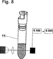
第8図は本発明による検定法の実施態様における第7図の段階の次の校正検定段階を示す斜視図、
第9図は本発明の検定法の実施に際しての本発明閉鎖装置の使用法を示す斜視図、また
第10図はテスト法の実際測定段階を示す斜視図である。
第1図について述べれば、図示の本発明による閉鎖装置の基本的部品は、テスト容器または反応器などの容器の口部の上に密着させられるような形状とサイズとを有するストッパ型本体部分1を含む。図示の本体部分1の実施態様を容器の口部の内側に密封装着するため、この本体部分はそのスカート上に環状密封リッジ6を備える。明かに、この本体部分を容器口部の外部に装着するように構成する事ができ、この場合、閉鎖装置は通常技術による本体部分の新規な成形および寸法定めを必要とする。
さらに本発明による閉鎖装置は、第2図において最もよく見られるような軸方向に延在する孔2を備える。この孔2の中に挿入され滑りばめされて軸方向に移動するようなサイズを有するプランジャ3が第3図に図示されている。閉鎖装置の本体部分の孔2の内側面とプランジャ3の外側面との間の密封のため、プランジャスカートは相互に離間された複数の円形密封リッジ5を備え、これらのリッジは後述の特殊機能を有する。
本発明によれば、中央を通る孔2の内側面は孔壁体にそって軸方向に走る複数のグルーブ4を備える。これらのグルーブ4は、本体部分1がテスト容器の口部の上に挿入された時にテスト容器から外側に向けられる本体部分の末端から始まる。これらのグルーブ4はテスト容器の前記口部から、本体部分の孔の一定軸方向長さにそって延在する。またこれらのグルーブ4の深さは、本体部分の孔2中のプランジャ3のいかなる位置においてもプランジャ3の密封リッジ5がこれらのグルーブ4を閉塞しない程度に深い。
本体部分1の本質的部品は、本体部分がテスト容器の口部に搭載された時にテスト容器の内部に向けられるように本体部分1の末端に形成されたフタ構造7である。このフタ7の機能は本体部分1の孔2の容器側末端を閉鎖し、必要ならばこの孔2を開放するにある。フタ7の開放は通常のように、プランジャ3を孔2の中に滑り込ませる事によって実施される。フタ7は望ましくはヒンジ8によって本体部分1に対して連接され、このヒンジ8が閉鎖装置の種々の動作位置においてフタ7を本体部分1に固着する。フタ7の内側面は凹部9を含み、この凹部9はそれ自体、テスト試薬を密封保持するために閉鎖装置の中に備えられたスペース部分を成す。
プランジャ3の環状密封リッジ5は、テスト容器の内部に対向するプランジャ末端に近く配置される。これらのリッジは図示の実施態様においては3個であって、閉鎖フタ7とこのフタ7に対向するプランジャ3の下端との間に残存する孔2のスペースから大気中へのガス流通を保持する事によって閉鎖装置の段階的組立てを実施させる。この状態は第4図に図示の本体部分1とプランジャ3との相対位置から明かであって、この場合、プランジャ3の密封リッジ5はなおも本体部分1のグルーブ4の中に配置されている。プランジャ3がさらに内側に押されると、プランジャ3の下方リッジ5が本体部分の孔2のグルーブを有しない内側面に到達して、プランジャ3の下方のスペースと外気との連通を遮断する。
第4図に図示の装置の組立て状態は試薬スペース9と外気との間のガス流通を可能とする状態であって、予め前記スペース9の中に充填された試薬の製剤段階に使用する事ができる。このような処理は例えば試薬を検定に適した状態また/あるいは検定前の試薬の貯蔵処理段階に必要な状態にもたらす処理を含む。このような製剤段階は、検定試薬の乾燥凍結による親液化処理、および/または不活性ガス中の貯蔵、試薬の滅菌または大気とのガス流通状態で実施されるその他の通常処理を含む事ができる。
本発明の閉鎖装置の応用例は光学測定に基づく検定法を含み、この検定に際しては試薬を適当に調合して検定に適した状態に準備しなければならない。試薬の正確な調合は閉鎖装置にペースト状試薬を装入する段階を含み、次にこの試薬を急速検定反応のために粒状にもたらさなければならない。この段階は試薬ペーストから湿分を除去するために、前記の親液化処理を使用して実施する事ができる。
この検定段階に際して、本体部分1の中にプランジャ3を挿入し、第5図に図示のその初位置から第6図に図示の位置まで押すと、プランジャ3が本体部分孔2の内側末端のフタ7を押してスナップ開放させる。そこで、スペース9の中に貯蔵された試薬がテスト容器の中に落下し、このテスト容器の中で検定が通常のように実施される。
プランジャ3と本体部分1の相対挿入位置を確認し従って閉鎖装置の作動状態を表示するため、本体部分1は望ましくは位置表示器またはストッパ10を備える。このようにして、プランジャ3がこのストッパ10に対してそれぞれ第4図、第5図および第6図に図示の位置まで押し下げられる時、所望動作に対するプランジャの正確な位置が検証される。同時に、ストッパ10は望ましくない動作に対する防止手段として作用し、閉鎖装置が第5図に図示の貯蔵位置または使用可能位置にある時にプランジャ3とストッパ10を相互に固着シールによって連結する事ができる。
第7図乃至第10図について本発明による方法を下記に説明する。
免疫学的定量検定および定性検定に際して、生理液、分泌液または組織液(血液、血清、血漿、脊髄液、胸膜分泌液、腹水、膿、外傷化膿液、尿、痰、糞、咽頭塗布標本など)から一般に抗体濃度または抗原濃度が測定される。これらのテストはその性質上、直接的、間接的または抑制的である。免疫学検定に際しては、抗体はその抗体に特異の抗原構造に結合する。検定の前に、抗体または抗原が特異性標識薬(マーカ)に結合される。このようなマーカは、特にポリマー粒子(染色粒子および磁性粒子を含む)、コロイド金、染色基質、蛍光およびリン光分子および発光分子から成るグループから選定される。
定量検定は代表的には光学測定技術(吸光、消光、ネフェロメトリー、反射、蛍光、リン光、発光およびその他)に基づく分析装置を使用する。多くの場合、このような光学測定は誤差を発生する光学バックグラウンドファクタ(患者の状態に依存する標本の脂質濃度、黄疸指数およびその他の変数など)の排除を前提とする。
このようなバックグラウンド除去はブランク標本検定と呼ばれ、実際アナライトの検定前に器機を使用して実施される。ブランク標本の測定後に、標本溶液に特異試薬を添加して標本アナライトの反応を検出するために、検定に使用される分析装置を始動する。前記の信号変化は標本中で検定されるアナライト濃度に比例するように選定される。
本発明による方法および装置は、広く相違するバックグラウンド特性を有する全血液などの標本中のアナライトの正確な検定を容易に実施する事ができる。
バックグラウンド除去を可能にするため(ブランク標本を使用するため)、検定されるアナライトとの特異反応のための試薬はバックグラウンド除去測定の後においてのみ標本に対して加えられる。このような操作順序は本発明による閉鎖装置によって容易に実施される。本発明による方法においては、試薬スペース9が免疫テストの特異性標識化合物を充填され、この場合、マーカは遊離試薬の形を成し(例えば、酵素基質)または特定の抗体または抗原に結合される試薬(例えばマーカ粒子あるいはコロイド金の標識を付けられた物質)である。これらの抗体分子または抗原分子が検定に必要な信号を生じる事ができる。試薬結合または変色を検出するために光学技術が使用され、この場合、必要なら速度測定が可能である。測定システムにおいて、本発明による閉鎖装置は検定容器のストッパとして使用する事ができる。
テストに際して、検定容器11中に(第7図参照)所要量の緩衝溶液が添加され、この緩衝溶液は本発明においては容器中に導入される標本の中で所要の準備反応(例えば、溶血として知られる赤血球の分解、または他の免疫検定において有害ファクタであるリュウマチ性ファクタの補体のClq成分の不活性化)を実施する事のできる緩衝溶液が選定される。緩衝溶液と標本の添加後に、容器を本発明による装置によって密封する事ができ、この装置が容器の閉鎖手段として作用し、次に容器の内容物を撹拌する。この段階における試薬スペース9はなおも標本容器から分離されているので、標識化合物は標本と緩衝液とによって形成された溶液と混合する事ができない。
必要なら、ある種の試薬、例えば溶血化合物(サポニン)または赤血球凝集化合物(レクチン)を閉鎖装置中のフタ7の外側面に配置する事ができ、この場合これらの化合物が実際の免疫反応前に所望の予備的反応(溶血、赤血球の凝集)を実施する事ができる。
予備的処理後に(第8図)、標本容器を光学測定検定装置の中に配置し、バックグラウンド除去の第1測定段階を(ブランク標本に対して)実施する。
バックグラウンド除去後に、本発明の閉鎖装置のプランジャを押し下げてフタ7を開く事により、試薬スペース9から標本容器の内部に達する通路を開く(第9図)。フタが開かれると、本発明の閉鎖装置と容器とから成る組立体を撹拌する事により特異性標識化合物がスペース9から放出される。この試薬添加段階後に、標識化合物とアナライトとの特異性反応が標本バックグラウンドからの干渉なしで光学法によって測定される(第10図参照)。
従って本発明は特異性試薬の簡単な貯蔵、転送および所望の瞬間における正確な投与を容易に実施する事ができる。さらに、本発明による装置は分析システムまたは検定パッケージ(テストキット)の機能部分として使用する事ができる。
以下、本発明の免疫検定法を図面に示す二、三の実施例について詳細に説明するが本発明はこれに限定されない。
実施例 1
C−反応性タンパク質(CRP)は一般に採用されている炎症指示薬であって、患者の全血または血清の標本からのその検定が標準的ルーチンを成している。CRP検定に関連して、代表的にはこの標本は光学技術(吸光、消光、ネフェロメトリー、反射、蛍光、リン光、発光およびその他)に基づくシステムを使用して分析される。この測定は、バックグラウンド除去のための標本(ブランク標本)の予備的測定を必要とし、この段階は実際アナライトの検定に先だってシステムによって実施される。標本容器は種々の型の緩衝溶液を含む事ができる。実際に、CRP検定におけるバックグラウンド除去のための測定は、溶血緩衝溶液を収容した標本容器の中に全血または血清の標本を添加する事によって実施される。あるいは溶血試薬を、標本溶液に向けられたフタの外側面に配置する事ができる。この場合、検定される標本を、例えばプランジャを備えた毛管注射器を使用して標本容器の中に投与する事ができる。次に、容器のストッパとして作用する本発明の閉鎖装置によって容器を閉鎖し、その後、緩衝溶液と標本を撹拌する。標本の撹拌と、緩衝溶液中の赤血球の溶血との後に、標本容器を分析装置の中に配置する。標本のバックグラウンド測定読み値を記録し、標本(ブランク標本)のゼロ値として設定する。
標本のバックグラウンド除去後に、装置は特異性反応物のCRPとの反応を記録し、この反応は本発明による閉鎖装置からの反応物の分離とこれに続くそのCRPとの混合によって開始される。この場合、標本の他の光学特性とは無関係の信号変化が得られる。従ってこの信号変化は検定される標本中のCRPの濃度に比例させられる。このような構造は、全血などの相異なるバックグラウンド特性を有する標本中のCRP濃度の正確な検定を容易に実施する事ができる。
ブランク標本に対するバックグラウンド除去を可能とするため、CRP検定用の特異性試薬はバックグラウンド除去段階の後においてのみ添加する事ができる。前記の方法において、試薬スペース9はCRP抗体を塗布された冷凍乾燥(親液性)ポリマー粒子を収容する。またCRP分子は抗体分子に特異的に結合して被覆されたポリマー粒子の凝集を生じるので、光学技術による反応速度の動的測定が可能である。もちろん、通常使用される任意の他の型のマーカを使用する事ができる(例えば、コロイド金、磁性粒子、染色粒子、染色アグリゲートおよびその他)。
実施例 2
リューマチ性ファクタ(RF)の検定は各種のリューマチ疾患の診断においてきわめて重要である。RF検定は直接に全血または血清標本について実施する事ができる。このテストにおいて、特異性標識粒子に人の免疫グロブリン−G分子を被覆する。検定反応の緩衝溶液は、溶血化合物のほか、ポリアニオン分子を含有する事ができ、このポリアニオン分子は、さもなければ免疫グロブリン−GのFcフラグメントに結合する事によってRF−標識剤と非特異性反応する可能性のあるいわゆる補体のClq成分に結合する。実際テストの各段階は実施例1と同一の順序で実施される。血液標本の添加後に、検定緩衝溶液のポリアニオン分子がClq成分に結合して、非特異性反応を効果的に防止するが、全血標本が検定されている場合には赤血球の分解(溶血)が同時的に生じる。標本の添加後に、(ブランク標本を使用した)バックグラウンド除去が実施例1と同様に実施される。本発明による閉鎖装置のフタ7を開く事により実際の特異性反応が開始されるので、人免疫グロブリン−Gを塗布された粒子がRFと反応する。このようにして形成されたアグリゲートが実施例1と同様にして測定される。The present invention relates to a closure device suitable for use in performing assays, particularly clinical tests on biological fluids such as blood. The object of the present invention is to make the reagent used for the assay in a state that guarantees a reliable test result, hold this state for a long time and under harmful environmental conditions, and further test the sample to be assayed. It is an object of the present invention to provide a closing device that allows a reagent to be added at a desired moment.
Another object of the present invention is under conditions that are maximally protected to remove, on the one hand, error factors added to the test results by the environment and on the other hand to reduce the risk of contamination applied to the environment by the test. It is in providing the closing device which can perform the said test | inspection.
These or other objectives are intended for any desired moment when a reagent formulated in a state suitable for assay is in a closure device having a basic structure designed as a closure assembly suitable for closing a diagnostic test container. This is accomplished by a closure device that is sealed to be released from the closure device into a diagnostic test container.
Closure devices having a similar basic structure are known in the art and have been considered for use, for example, in pharmaceutical formulations. In this application, one or more components of the drug product are placed in a drug bottle or similar container immediately prior to use of the drug without the active therapeutic agent being dispensed prior to the moment of its required use. Added to other stored ingredients. The former component is stored in a closed space such as a lid of a medicine bottle before its addition, and the ingredient is opened by opening the passage from the inside of the lid into the medicine bottle by pushing down or similar operation. Can be used. Closing devices having such a basic structure are in particular patents GB 1,193,989, GB 1,479,370, EP 0,093,090, EP 0,338,349, EP 0,561,322 and EP 0, 344,849.
However, these conventional closure devices require that the reagents used in the test be in a state that is convenient for the assay in order to perform tests that are effective in many medical and similar applications. The state needs to be maintained until the moment of testing, which does not take into account that the moment of testing is essentially after the usable moment of manufacture of the closure device. In addition, the conditions that exist during the ready-to-use waiting period have been inconvenient for reagent stability, especially when the test kit is used outdoors.
According to the invention, it has a basic structure designed as a closure assembly suitable for closing a diagnostic test container or similar container, the closure device comprising a body part and a plunger, the body part comprising the body part A lid suitable for tightly mounting on the mouth of the container and having a cylindrical hole in the axial direction thereof, and the body portion being adapted to openably close the end of the hole of the body portion facing the diagnostic test container. And the plunger has a diameter corresponding to the hole in the body portion, the plunger being slidably mounted in the hole and moving to a sealed position relative to the body portion, A book that solves these problems by a closure device configured to form a sealed reagent storage chamber in the space remaining between the lid of the hole and the plunger. Improvements are provided. The essential features of the closure device according to the invention are apparent from
The invention also relates to a method for assaying a specimen, in particular a specimen of physiological fluid, by reacting the specimen with an assay reagent comprising a reagent aliquot which is stored in and discharged from the closure device which seals the test container. Is. The features of this method are described in claim 8. Furthermore, the present invention particularly relates to a test kit for performing a clinical test of a specimen such as a blood specimen. The test kit includes at least one test container sealed by a lid containing a reagent, wherein the reagent is subjected to a processing step before the closure device is sealed off from communication with outside air. To do.
Hereinafter, the present invention will be described in detail with reference to embodiments shown in the drawings, but the present invention is not limited thereto. In the attached figure,
FIG. 1 is a cross-sectional view showing a partial cross section of a body portion of a closure device according to the present invention;
FIG. 2 is a sectional view taken along the line AA of the main body portion of FIG.
FIG. 3 shows another basic part of the closure device according to the invention, a partial sectional view of the plunger,
FIG. 4 is a partial sectional view showing a state immediately before filling of the closing device according to the present invention,
FIG. 5 is a partial cross-sectional view showing a state immediately before use of the closure device according to the present invention,
FIG. 6 is a partial sectional view showing the operating state of the closing device according to the present invention,
FIG. 7 is a perspective view showing the dispensing stage of one embodiment of the assay method of the invention using a closure device according to the invention,
FIG. 8 is a perspective view showing a calibration test step next to the step of FIG. 7 in the embodiment of the test method according to the present invention;
FIG. 9 is a perspective view showing how to use the closure device of the present invention in carrying out the test method of the present invention, and FIG. 10 is a perspective view showing an actual measurement stage of the test method.
Referring to FIG. 1, the basic part of the closure device according to the invention shown is a stopper-
Furthermore, the closure device according to the invention comprises an axially extending
According to the present invention, the inner surface of the
The essential part of the
The
The assembled state of the apparatus shown in FIG. 4 is a state that allows gas flow between the
Applications of the closure device of the present invention include an assay based on optical measurements, where the reagents must be prepared appropriately and prepared for the assay. Accurate formulation of the reagent involves charging the closed device with the pasty reagent, which must then be brought into a granular form for a rapid assay reaction. This step can be performed using the lyophilic process described above to remove moisture from the reagent paste.
In this verification step, the
In order to confirm the relative insertion position of the
The method according to the invention will be described below with reference to FIGS.
Physiological fluids, secretions or tissue fluids (blood, serum, plasma, spinal fluid, pleural secretions, ascites, pus, traumatic pus, urine, sputum, feces, pharyngeal specimens, etc.) Generally, antibody concentration or antigen concentration is measured. These tests are direct, indirect or inhibitory in nature. In an immunological assay, the antibody binds to an antigen structure specific for that antibody. Prior to the assay, the antibody or antigen is bound to a specific labeling agent (marker). Such markers are selected in particular from the group consisting of polymer particles (including stained particles and magnetic particles), colloidal gold, stained substrates, fluorescent and phosphorescent molecules and luminescent molecules.
Quantitative assays typically use analyzers based on optical measurement techniques (absorption, quenching, nepherometry, reflection, fluorescence, phosphorescence, luminescence and others). In many cases, such optical measurements presuppose the elimination of optical background factors (such as sample lipid concentration, jaundice index, and other variables that depend on the patient's condition) that generate errors.
Such background removal is called a blank sample test and is actually performed using an instrument prior to the assay of the analyte. After the measurement of the blank sample, the analyzer used for the assay is started in order to add a specific reagent to the sample solution and detect the reaction of the sample analyte. The signal change is selected to be proportional to the analyte concentration tested in the sample.
The method and apparatus according to the present invention can easily perform an accurate assay of an analyte in a sample such as whole blood having widely different background characteristics.
In order to allow background removal (to use a blank sample), reagents for a specific reaction with the analyte being assayed are added to the sample only after the background removal measurement. Such an operating sequence is easily carried out by the closing device according to the invention. In the method according to the invention, the
During the test, a required amount of a buffer solution is added to the assay container 11 (see FIG. 7). In the present invention, this buffer solution is used as a required preparatory reaction (for example, as hemolysis) in the specimen introduced into the container. A buffer solution is selected that can carry out known red blood cell degradation, or inactivation of the Clq component of complement of rheumatoid factor, which is a detrimental factor in other immunoassays. After the addition of the buffer solution and the specimen, the container can be sealed with the device according to the invention, which acts as a container closure means and then agitates the contents of the container. Since the
If necessary, certain reagents, such as hemolytic compounds (saponins) or hemagglutinating compounds (lectins), can be placed on the outer surface of the
After preliminary processing (FIG. 8), the specimen container is placed in an optical measurement assay device and the first measurement stage of background removal is performed (on the blank specimen).
After the background is removed, the passage reaching from the
Thus, the present invention allows easy storage, transfer and accurate administration of specific reagents at the desired moment. Furthermore, the device according to the invention can be used as a functional part of an analysis system or an assay package (test kit).
Hereinafter, the immunoassay method of the present invention will be described in detail with reference to a few examples shown in the drawings, but the present invention is not limited thereto.
Example 1
C-reactive protein (CRP) is a commonly adopted inflammatory indicator, and its assay from patient whole blood or serum specimens has become a standard routine. In connection with the CRP assay, this specimen is typically analyzed using a system based on optical techniques (absorption, quenching, nephelometry, reflection, fluorescence, phosphorescence, luminescence and others). This measurement requires a preliminary measurement of the specimen (blank specimen) for background removal, and this stage is actually performed by the system prior to the assay of the analyte. The specimen container can contain various types of buffer solutions. In practice, the measurement for background removal in the CRP assay is performed by adding a whole blood or serum sample into a sample container containing a hemolysis buffer solution. Alternatively, the hemolytic reagent can be placed on the outer surface of the lid directed to the sample solution. In this case, the specimen to be assayed can be administered into the specimen container using, for example, a capillary syringe with a plunger. The container is then closed by the closure device of the present invention which acts as a stopper for the container, after which the buffer solution and specimen are agitated. After sample agitation and lysis of red blood cells in buffer solution, the sample container is placed in the analyzer. Record the background measurement reading of the specimen and set it as the zero value of the specimen (blank specimen).
After removal of the sample background, the device records the reaction of the specific reactant with CRP, which reaction is initiated by separation of the reactant from the closed device according to the invention followed by its mixing with CRP. In this case, signal changes that are independent of other optical properties of the specimen are obtained. This signal change is therefore proportional to the concentration of CRP in the sample to be assayed. Such a structure can easily perform an accurate assay of CRP concentration in specimens having different background characteristics such as whole blood.
Specific reagents for CRP assays can only be added after the background removal step to allow background removal for blank specimens. In the above method,
Example 2
Rheumatoid factor (RF) assays are extremely important in the diagnosis of various rheumatic diseases. The RF assay can be performed directly on whole blood or serum specimens. In this test, specific labeled particles are coated with human immunoglobulin-G molecules. The buffer solution of the assay reaction can contain a polyanion molecule in addition to the hemolytic compound, which otherwise binds to the Fc fragment of immunoglobulin-G, thereby causing a nonspecific reaction with the RF-labeling agent. It binds to the so-called complement Clq component. Actual test steps are performed in the same order as in the first embodiment. After the blood sample is added, polyanion molecules in the assay buffer bind to the Clq component, effectively preventing non-specific reactions, but if the whole blood sample is assayed, red blood cell degradation (hemolysis) may occur. It occurs at the same time. After sample addition, background removal (using a blank sample) is performed as in Example 1. Since the actual specific reaction is started by opening the
Claims (7)
前記本体部分(1)を軸方向に貫通する孔(2)の内側面は少なくとも1つのグルーブ(4)を備え、このグルーブ(4)の放射方向深さは前記プランジャ(3)の外径の到達範囲内にない程度に深く、前記グルーブ(4)は前記孔(2)の外端から、孔(2)の内側面にそって軸方向に、前記プランジャ(3)が前記孔(2)の中に部分的に挿入された時に前記試薬貯蔵チャンバ(9)と前記円筒形孔(2)の外端との間のガス流通を保持する事のできる長さ延在する事を特徴とする閉鎖装置。A closure device suitable for use in performing assays, particularly clinical tests involving physiological fluids, said closure device being designed as a closure assembly suitable for closing a diagnostic test container or similar container The closure device comprises a body part (1) and a plunger (3), the body part (1) being suitable for tight mounting on the mouth of the container and cylindrical in its axial direction Comprising a hole (2), the body part (1) comprising a lid (7) suitable for releasably closing the end of the hole (2) of the body part (1) facing the diagnostic test container; The plunger (3) has a diameter corresponding to the hole (2) of the main body part (1) and is slidably mounted in the hole (2) to be sealed against the main body part (1). Move to the position of the hole (2) in the body part (1) In configured closure device to be able to form a sealed reagent storage chamber (9) in the space remaining between the serial the plunger and lid (7) (3),
The inner surface of the hole (2) passing through the body portion (1) in the axial direction is provided with at least one groove (4), and the radial depth of the groove (4) is the outer diameter of the plunger (3). The groove (4) is not deep within the reachable range, the groove (4) extends axially along the inner surface of the hole (2) from the outer end of the hole (2), and the plunger (3) extends to the hole (2). When it is partially inserted into the tube, it extends for a length capable of maintaining gas flow between the reagent storage chamber (9) and the outer end of the cylindrical hole (2). Closure device.
Applications Claiming Priority (3)
| Application Number | Priority Date | Filing Date | Title |
|---|---|---|---|
| FI962542A FI102642B1 (en) | 1996-06-19 | 1996-06-19 | Reaction vessel or similar stopper |
| FI962542 | 1996-06-19 | ||
| PCT/FI1997/000388 WO1997048492A1 (en) | 1996-06-19 | 1997-06-18 | Stopper having a cavity for reagents and an assay method using said stopper |
Publications (2)
| Publication Number | Publication Date |
|---|---|
| JP2000501191A JP2000501191A (en) | 2000-02-02 |
| JP3696253B2 true JP3696253B2 (en) | 2005-09-14 |
Family
ID=8546242
Family Applications (1)
| Application Number | Title | Priority Date | Filing Date |
|---|---|---|---|
| JP50239098A Expired - Lifetime JP3696253B2 (en) | 1996-06-19 | 1997-06-18 | Stopper with reagent cavity and assay using said stopper |
Country Status (12)
| Country | Link |
|---|---|
| US (1) | US6149866A (en) |
| EP (1) | EP0859664B1 (en) |
| JP (1) | JP3696253B2 (en) |
| CZ (1) | CZ296932B6 (en) |
| DE (1) | DE69719951T2 (en) |
| DK (1) | DK0859664T3 (en) |
| ES (1) | ES2193378T3 (en) |
| FI (1) | FI102642B1 (en) |
| HU (1) | HU225030B1 (en) |
| NO (1) | NO319596B1 (en) |
| PL (1) | PL183800B1 (en) |
| WO (1) | WO1997048492A1 (en) |
Families Citing this family (40)
| Publication number | Priority date | Publication date | Assignee | Title |
|---|---|---|---|---|
| DE19850934C2 (en) * | 1998-11-05 | 2001-07-12 | Lange Gmbh Dr Bruno | Closure element for closing, storing and introducing reagents and / or auxiliary substances into a reaction container |
| GB2365414A (en) * | 2000-07-31 | 2002-02-20 | Cambridge Life Sciences | Storage devices for fluids |
| US7482116B2 (en) | 2002-06-07 | 2009-01-27 | Dna Genotek Inc. | Compositions and methods for obtaining nucleic acids from sputum |
| DE20209513U1 (en) * | 2002-06-19 | 2002-08-29 | Trw Automotive Electron & Comp | cap |
| US7210575B2 (en) * | 2002-09-26 | 2007-05-01 | Boehringer Ingelheim International Gmbh | Two-component packaging unit |
| EP1407820B1 (en) * | 2003-05-22 | 2009-08-19 | Agilent Technologies, Inc. | flap septum |
| US20050011821A1 (en) * | 2003-07-17 | 2005-01-20 | Sigma-Aldrich Co. | High throughput flash purification stand and cartridge |
| JP2007512194A (en) * | 2003-11-28 | 2007-05-17 | ヤン−クーク チョ | container |
| GB0401288D0 (en) | 2004-01-21 | 2004-02-25 | Orion Diagnostica Oy | Sampling and assay device |
| US8215481B1 (en) * | 2004-02-18 | 2012-07-10 | Knickerbocker Michael G | Container closure for retaining an additive material |
| WO2005087339A1 (en) * | 2004-03-04 | 2005-09-22 | Sigma-Aldrich Co. | A high throughput flash purification stand and cartridge |
| WO2006052827A2 (en) * | 2004-11-04 | 2006-05-18 | Viz Enterprises, Llc | Multi-chamber container and cap therefor |
| CA2588946C (en) * | 2004-12-16 | 2014-07-29 | Cepheid | Cap for vessel for performing multi-stage process |
| CN101194154A (en) * | 2005-06-08 | 2008-06-04 | 尼普洛株式会社 | Specimen sampling liquid container |
| AU2006324337C1 (en) * | 2005-12-09 | 2013-03-21 | Dna Genotek Inc. | Container system for releasably storing a substance |
| DE102008023341A1 (en) * | 2008-02-27 | 2009-06-25 | Elm - Plastic Gmbh | Pipette adapter for inserting into e.g. medicament containing bottle, has upwardly opened casing including crank with through opening at lower end, and inwardly opened casing including gaskets at outer side of inwardly opened casing |
| EP2292525A1 (en) * | 2009-09-04 | 2011-03-09 | Obrist Closures Switzerland GmbH | Container closure assembly |
| WO2011043783A2 (en) * | 2009-10-09 | 2011-04-14 | Qiagen | Closure and method of using same |
| FR2956463B1 (en) * | 2010-02-16 | 2012-06-29 | Biomerieux Sa | VALVE DEVICE, MONO-BODY, MOLD BY INJECTION OF ELASTIC MATERIAL |
| DE102010016054B3 (en) * | 2010-03-22 | 2011-09-22 | Kunststofftechnik Waidhofen An Der Thaya Gmbh | Closure with a chamber and component set for this |
| EP2371731A1 (en) | 2010-03-31 | 2011-10-05 | Roche Diagnostics GmbH | Reagent kit with transit support |
| US9027774B2 (en) | 2011-03-23 | 2015-05-12 | Ecotop, LLC | Drinking cup lid |
| EP2721140B1 (en) | 2011-06-19 | 2016-11-23 | Abogen, Inc. | Devices, solutions and methods for sample collection |
| GB2485254C (en) * | 2011-08-22 | 2013-12-25 | Eulysis Uk Ltd | A container having a recessed closure for drying and storing one or more active agents |
| US9067716B2 (en) | 2011-09-30 | 2015-06-30 | Federico Intriago | Cap assembly for dispensing a dispensable component and method of making and using the same |
| KR101168166B1 (en) * | 2012-02-29 | 2012-07-24 | 케이맥(주) | Detecting device for bio material |
| DE102012222351A1 (en) * | 2012-12-05 | 2014-06-05 | Gna Biosolutions Gmbh | Reaction vessel with magnetic closure |
| EP3004866B1 (en) * | 2013-05-24 | 2019-11-06 | Premier Biotech, Inc. | Multi-stage oral-fluid testing device |
| JP6167669B2 (en) * | 2013-05-30 | 2017-07-26 | 東亜ディーケーケー株式会社 | Phosphate measurement kit |
| US10076751B2 (en) | 2013-12-30 | 2018-09-18 | General Electric Company | Systems and methods for reagent storage |
| CN106132456B (en) * | 2014-01-20 | 2019-12-24 | 阿波根有限公司 | Apparatus, solution and method for sample collection |
| CN106456075B (en) * | 2014-05-21 | 2019-09-27 | 欧雷恩诊断公司 | Sampling and assay kit, sample holder and method |
| GB201415869D0 (en) * | 2014-09-08 | 2014-10-22 | Eulysis Uk Ltd | Container And Closure |
| US10456787B2 (en) * | 2016-08-11 | 2019-10-29 | Instrumentation Laboratory Company | Reagent component dispensing caps for reagent containers used in automated clinical analyzers |
| CN108357778B (en) * | 2017-01-26 | 2021-12-28 | 本诺瓦公司 | Cartridge for dispensing a product in a container |
| MX2019009955A (en) * | 2017-02-21 | 2019-12-19 | Ellume Pty Ltd | A diagnostic system. |
| WO2020106891A1 (en) | 2018-11-20 | 2020-05-28 | Spectrum Solutions, Llc | Sample collection system including sealing cap and valve |
| CN109852539A (en) * | 2019-03-05 | 2019-06-07 | 温州广立生物医药科技有限公司 | A kind of dissociative DNA in blood preservation pipe |
| CA3133975A1 (en) * | 2019-03-18 | 2020-09-24 | Siemens Healthcare Diagnostics Inc. | Diagnostic consumables incorporating coated micro-projection arrays, and methods thereof |
| US11701094B2 (en) | 2019-06-20 | 2023-07-18 | Spectrum Solutions L.L.C. | Sample collection system including valve and plug assemblies |
Family Cites Families (9)
| Publication number | Priority date | Publication date | Assignee | Title |
|---|---|---|---|---|
| US3715189A (en) * | 1970-06-15 | 1973-02-06 | Secretary Of The Treasury | Qualitative analysis device |
| US3756390A (en) * | 1972-03-07 | 1973-09-04 | American Cyanamid Co | Two-compartment aspirating disposable hypodermic syringe package |
| US4192429A (en) * | 1978-03-02 | 1980-03-11 | Becton, Dickinson And Company | Vented vacuum tube and stopper |
| US4221291A (en) * | 1978-06-20 | 1980-09-09 | General Foods Corporation | Container having separate storage facilities for two materials |
| DE3369297D1 (en) * | 1982-04-23 | 1987-02-26 | Capsulit Srl | A closure for bottles and the like of the type including a breakable bottom reservoir to break during use |
| ATE53671T1 (en) * | 1985-09-05 | 1990-06-15 | Graub Ag Ernst | VETERINARY REAGENT SET FOR RAPID TEST FOR DETERMINING BLOOD CALCIUM. |
| CS273009B1 (en) * | 1986-05-08 | 1991-02-12 | Marie Rndr Csc Jakoubkova | Impregnating terminal for permeant tube's filling renewal |
| US5496288A (en) * | 1992-09-23 | 1996-03-05 | Becton, Dickinson And Company | Protective cap for hypodermic syringe |
| DE69508629T2 (en) * | 1994-01-25 | 1999-10-14 | Becton Dickinson Co | Syringe and method for lyophilizing and restoring injectable drugs |
-
1996
- 1996-06-19 FI FI962542A patent/FI102642B1/en not_active IP Right Cessation
-
1997
- 1997-06-18 US US09/011,853 patent/US6149866A/en not_active Expired - Lifetime
- 1997-06-18 CZ CZ0035898A patent/CZ296932B6/en not_active IP Right Cessation
- 1997-06-18 WO PCT/FI1997/000388 patent/WO1997048492A1/en active IP Right Grant
- 1997-06-18 ES ES97927207T patent/ES2193378T3/en not_active Expired - Lifetime
- 1997-06-18 PL PL97325009A patent/PL183800B1/en unknown
- 1997-06-18 JP JP50239098A patent/JP3696253B2/en not_active Expired - Lifetime
- 1997-06-18 EP EP97927207A patent/EP0859664B1/en not_active Expired - Lifetime
- 1997-06-18 DK DK97927207T patent/DK0859664T3/en active
- 1997-06-18 HU HU9901456A patent/HU225030B1/en unknown
- 1997-06-18 DE DE69719951T patent/DE69719951T2/en not_active Expired - Lifetime
-
1998
- 1998-02-17 NO NO19980667A patent/NO319596B1/en not_active IP Right Cessation
Also Published As
| Publication number | Publication date |
|---|---|
| NO980667L (en) | 1998-03-25 |
| CZ296932B6 (en) | 2006-07-12 |
| WO1997048492A1 (en) | 1997-12-24 |
| NO319596B1 (en) | 2005-08-29 |
| EP0859664A1 (en) | 1998-08-26 |
| JP2000501191A (en) | 2000-02-02 |
| FI962542A0 (en) | 1996-06-19 |
| US6149866A (en) | 2000-11-21 |
| EP0859664B1 (en) | 2003-03-19 |
| DE69719951T2 (en) | 2004-01-08 |
| DK0859664T3 (en) | 2003-08-11 |
| CZ35898A3 (en) | 1998-07-15 |
| PL325009A1 (en) | 1998-07-06 |
| NO980667D0 (en) | 1998-02-17 |
| DE69719951D1 (en) | 2003-04-24 |
| PL183800B1 (en) | 2002-07-31 |
| HUP9901456A3 (en) | 1999-11-29 |
| HUP9901456A2 (en) | 1999-08-30 |
| FI102642B (en) | 1999-01-15 |
| FI962542A (en) | 1997-12-20 |
| HU225030B1 (en) | 2006-05-29 |
| FI102642B1 (en) | 1999-01-15 |
| ES2193378T3 (en) | 2003-11-01 |
Similar Documents
| Publication | Publication Date | Title |
|---|---|---|
| JP3696253B2 (en) | Stopper with reagent cavity and assay using said stopper | |
| US11759783B2 (en) | Assay device | |
| US4387164A (en) | Method and apparatus for chemical analysis using reactive reagents dispersed in soluble film | |
| JP3299271B2 (en) | Capillary blood antigen tester | |
| US4424279A (en) | Rapid plunger immunoassay method and apparatus | |
| AU2007205745B2 (en) | Immunoassay test device and method of use | |
| US8367023B2 (en) | Reagent vessel | |
| IE61300B1 (en) | Latex agglutination immunoassay in the presence of hemoglobin | |
| JP2002523779A (en) | Method and apparatus for performing a test | |
| JPH11316226A (en) | Cartridge for automatic measurement and automatic measuring method | |
| JP3447360B2 (en) | Method for performing an analytical assay and its reaction vessel | |
| US11740252B2 (en) | Apparatuses and methods for suspending and washing the contents of a plurality of cuvettes | |
| WO2014016236A1 (en) | Disposable test device | |
| JP2019500576A (en) | Determining the amount of specimen in a blood sample | |
| JPS62501447A (en) | Methods, devices and systems for performing biochemical assays | |
| US20190234944A1 (en) | Devices and methods to reduce interfering compounds in biological samples | |
| EP3917398A1 (en) | Sampling and assay kit and method for sampling a biological sample | |
| CN115190835A (en) | Method for removing interfering components from a liquid sample prior to dispensing the liquid sample on a chemical reagent test slide | |
| EP0801543A1 (en) | Device and method for transferring fluids for analysis | |
| CA2137238A1 (en) | Immunoassay method | |
| JP3543655B2 (en) | Sample confirmation method and kit | |
| CN111282615A (en) | Kit for clinical examination and application | |
| AU706430B2 (en) | Capillary blood antigen testing apparatus | |
| JPH09318623A (en) | Sampling and testing method for organic sample and simple testing device therefor | |
| JPH0543065B2 (en) |
Legal Events
| Date | Code | Title | Description |
|---|---|---|---|
| A621 | Written request for application examination |
Free format text: JAPANESE INTERMEDIATE CODE: A621 Effective date: 20040416 |
|
| A131 | Notification of reasons for refusal |
Free format text: JAPANESE INTERMEDIATE CODE: A131 Effective date: 20041124 |
|
| A711 | Notification of change in applicant |
Free format text: JAPANESE INTERMEDIATE CODE: A711 Effective date: 20041217 |
|
| A72 | Notification of change in name of applicant |
Free format text: JAPANESE INTERMEDIATE CODE: A721 Effective date: 20041217 |
|
| A521 | Request for written amendment filed |
Free format text: JAPANESE INTERMEDIATE CODE: A523 Effective date: 20050203 |
|
| TRDD | Decision of grant or rejection written | ||
| A01 | Written decision to grant a patent or to grant a registration (utility model) |
Free format text: JAPANESE INTERMEDIATE CODE: A01 Effective date: 20050531 |
|
| A61 | First payment of annual fees (during grant procedure) |
Free format text: JAPANESE INTERMEDIATE CODE: A61 Effective date: 20050629 |
|
| R150 | Certificate of patent or registration of utility model |
Free format text: JAPANESE INTERMEDIATE CODE: R150 |
|
| FPAY | Renewal fee payment (event date is renewal date of database) |
Free format text: PAYMENT UNTIL: 20090708 Year of fee payment: 4 |
|
| FPAY | Renewal fee payment (event date is renewal date of database) |
Free format text: PAYMENT UNTIL: 20090708 Year of fee payment: 4 |
|
| FPAY | Renewal fee payment (event date is renewal date of database) |
Free format text: PAYMENT UNTIL: 20100708 Year of fee payment: 5 |
|
| FPAY | Renewal fee payment (event date is renewal date of database) |
Free format text: PAYMENT UNTIL: 20110708 Year of fee payment: 6 |
|
| FPAY | Renewal fee payment (event date is renewal date of database) |
Free format text: PAYMENT UNTIL: 20110708 Year of fee payment: 6 |
|
| FPAY | Renewal fee payment (event date is renewal date of database) |
Free format text: PAYMENT UNTIL: 20120708 Year of fee payment: 7 |
|
| FPAY | Renewal fee payment (event date is renewal date of database) |
Free format text: PAYMENT UNTIL: 20120708 Year of fee payment: 7 |
|
| FPAY | Renewal fee payment (event date is renewal date of database) |
Free format text: PAYMENT UNTIL: 20130708 Year of fee payment: 8 |
|
| R250 | Receipt of annual fees |
Free format text: JAPANESE INTERMEDIATE CODE: R250 |
|
| R250 | Receipt of annual fees |
Free format text: JAPANESE INTERMEDIATE CODE: R250 |
|
| R250 | Receipt of annual fees |
Free format text: JAPANESE INTERMEDIATE CODE: R250 |
|
| R250 | Receipt of annual fees |
Free format text: JAPANESE INTERMEDIATE CODE: R250 |
|
| EXPY | Cancellation because of completion of term |