JP3696191B2 - OFDM transceiver - Google Patents
OFDM transceiver Download PDFInfo
- Publication number
- JP3696191B2 JP3696191B2 JP2002273410A JP2002273410A JP3696191B2 JP 3696191 B2 JP3696191 B2 JP 3696191B2 JP 2002273410 A JP2002273410 A JP 2002273410A JP 2002273410 A JP2002273410 A JP 2002273410A JP 3696191 B2 JP3696191 B2 JP 3696191B2
- Authority
- JP
- Japan
- Prior art keywords
- transmission
- ofdm
- condition setting
- subcarriers
- transmission condition
- Prior art date
- Legal status (The legal status is an assumption and is not a legal conclusion. Google has not performed a legal analysis and makes no representation as to the accuracy of the status listed.)
- Expired - Fee Related
Links
Images


Landscapes
- Mobile Radio Communication Systems (AREA)
Description
【0001】
【発明の属する技術分野】
本発明は、OFDM(直交周波数分割多重:Orthogonal Frequency Division Multiplexing)信号を伝送する無線通信システムにおけるOFDM送受信装置に関する。
【0002】
【従来の技術】
一般に、無線通信システムでは、伝送された信号が建物などによる電波の反射により複数の様々な経路(マルチパス)を経由して受信されるため、受信信号に歪みが生じる。この歪みは、場所や時間によって変動する。このような伝播環境下では、伝播環境に応じて変調方式や符号化率等の送信条件を変更することによって、データ伝送の実効速度を最大化することができる。通常、受信機が既知の参照系列やデータ系列から受信電界強度や伝送路応答を求めることによって、伝播環境に適した送信条件を設定することができる。
【0003】
伝送される信号がOFDM信号のような広帯域の信号である場合には、マルチパスによって周波数選択性フェージングが生じる。周波数選択性フェージングが生じると、OFDM信号を構成する複数の周波数の異なったサブキャリア毎に受信電界強度が異なる結果、受信特性の優れたサブキャリアと劣悪なサブキャリアが混在する。受信特性の劣悪なサブキャリアの存在により、全サブキャリアの平均的な受信電界強度や伝送路応答が優れていても、誤りの生じる可能性が増加する。従って、全サブキャリアの平均的な伝播環境に適した送信条件を選択したとしても、データ伝送の実効速度改善に大きな効果が得られない場合がある(たとえば、特許文献1参照)。
【0004】
【特許文献1】
米国特許第6,175,550号明細書
【0005】
【発明が解決しようとする課題】
上述のように従来のOFDM送受信装置では、全サブキャリアの平均的な伝送路応答や受信電界強度に応じて送信条件を設定するため、受信特性が劣悪なサブキャリアが存在すると、設定した送信条件でデータ伝送の実効速度を上げることができないという問題があった。
【0006】
本発明は、サブキャリア毎の伝送路応答に応じた最適な送信条件を設定することにより、データ伝送の実効速度を改善できるOFDM送受信装置を提供することを目的とする。
【0007】
【課題を解決するための手段】
上記課題を解決するため、本発明の第1の態様によるOFDM送受信装置は、
所定の伝送路を介して複数のサブキャリアを有するOFDM信号の送信および受信を相手局送受信装置との間で行うOFDM送受信装置において、
前記相手局送受信装置から送信されるOFDM信号を受信する受信手段と、
受信されたOFDM信号から、前記複数のサブキャリアに対する前記伝送路の応答特性を示す伝送路応答を算出する伝送路応答算出手段と、
算出された前記伝送路応答の所定の特性値を所定の閾値と比較し、該特性値が該閾値を超えるサブキャリア数の全サブキャリア数に対する割合を算出する比較手段と、
少なくとも前記比較手段により算出された割合を送信条件設定指標として、該送信条件設定指標に基づき当該OFDM送受信装置が前記相手局送受信装置にOFDM信号を送信する際の送信条件を設定する送信条件設定手段と、
設定された送信条件に従ってOFDM信号を送信する送信手段と
を備えるものである。
【0008】
本発明の第2の態様によるOFDM送受信装置は、
所定の伝送路を介して複数のサブキャリアを有するOFDM信号の送信および受信を相手局送受信装置との間で行うOFDM送受信装置において、
前記相手局送受信装置から送信されるOFDM信号を受信する受信手段と、
受信されたOFDM信号から、前記複数のサブキャリアに対する前記伝送路の応答特性を示す伝送路応答を算出する伝送路応答算出手段と、
算出された前記伝送路応答の所定の特性値を所定の閾値と比較し、該特性値が該閾値を超えるサブキャリア数の全サブキャリア数に対する割合を算出する比較手段と、
少なくとも前記比較手段により算出された割合を送信条件設定指標として前記相手局送受信装置が当該OFDM送受信装置にOFDM信号を送信する際の送信条件を設定するための送信条件設定情報を生成する送信条件設定情報生成手段と、
前記送信条件設定情報を前記相手局送受信装置に送信する送信手段と
を備えるものである。
【0009】
本発明の第3の態様によるOFDM送受信装置は、
所定の伝送路を介して複数のサブキャリアを有するOFDM信号の送信および受信を相手局送受信装置との間で行うOFDM送受信装置において、
前記相手局送受信装置から送信されるOFDM信号を受信する受信手段と、
受信されたOFDM信号から、前記複数のサブキャリアに対する前記伝送路の応答特性を示す伝送路応答を算出する伝送路応答算出手段と、
算出された前記伝送路応答の所定の特性値を所定の閾値と比較し、該特性値が該閾値を超えるサブキャリア数の全サブキャリア数に対する割合を算出する比較手段と、
少なくとも前記比較手段により算出された割合を前記相手局送受信装置が当該OFDM送受信装置にOFDM信号を送信する際の送信条件を設定する際の送信条件設定指標として該送信条件設定指標の情報を合成する送信条件設定指標情報合成手段と、
前記送信条件設定指標の情報を前記相手局送受信装置に送信する送信手段と
を備えるものである。
【0010】
以上の構成によれば、受信したOFDM信号に基づいてサブキャリア毎の伝送路応答に応じた最適な送信条件を設定することにより、OFDM信号を受信したOFDM送受信装置が送信するデータのデータ伝送の実効速度を改善することが可能になる。
【0011】
また、相手局送受信装置から受信したOFDM信号のサブキャリア毎の伝送路応答に基づいて、相手局送受信装置が自局送受信装置にOFDM信号を送信する際の送信条件を設定するための送信条件設定情報が、自局送受信装置から相手局送受信装置に送信される。相手局送受信装置は、送信された送信条件設定情報に基づいて送信条件を設定することにより、相手局送受信装置が自局送受信装置に送信してくるデータのデータ伝送の実効速度を改善することが可能になる。
【0012】
さらに、相手局送受信装置から受信したOFDM信号のサブキャリア毎の伝送路応答に基づいて、相手局送受信装置が自局送受信装置にOFDM信号を送信する際の送信条件を設定する際の送信条件設定指標が、自局送受信装置から相手局送受信装置に送信される。相手局送受信装置は、送信された送信条件設定指標に基づいて送信条件を設定することにより、相手局送受信装置が送信してくるデータのデータ伝送の実効速度を改善することが可能になる。ここで、送信条件設定指標は、送信条件を設定するためのインデックスとなる情報であり、送信条件設定情報よりもデータ量が少ない。従って、自局送受信装置から相手局送受信装置に送信されるデータ量が少なくて済むという効果がある。
【0013】
【発明の実施の形態】
以下、図面を用いて本発明の実施の形態について説明する。
本発明の実施形態に係るOFDM送受信装置は、基地局と端末とからなる移動無線通信システムや無線LANシステムに適用される。OFDM送受信装置は端末に搭載されていてもよいし、基地局に搭載されていてもよい。前者の場合、相手局送受信装置は基地局に搭載されたOFDM送受信装置であってもよいし、他の移動端末に搭載されたOFDM送受信装置であってもよい。後者の場合、相手局送受信装置は端末もしくは他の基地局に搭載される。
【0014】
(第1の実施形態)
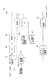
図1は、本発明の第1の実施形態に係るOFDM送受信装置の構成を示すブロック図である。本実施形態のOFDM送受信装置は、当該OFDM送受信装置(自局送受信装置)が受信したOFDM信号の受信電界強度と、このOFDM信号を構成する複数のサブキャリアにそれぞれ対応する伝送路応答の特性値が所定の閾値を超える割合を送信条件設定指標として、これらの送信条件設定指標に基づき相手局送受信装置にOFDM信号を送信する際の送信条件を設定する。
【0015】
まず、本実施形態のOFDM送受信装置(自局送受信装置)が相手局送信装置に送信を行うための送信側の構成について説明する。
送信データ系列10は、サブキャリア変調部11に入力されることによって、周波数軸上で直交した複数のサブキャリア信号に変換される。サブキャリア変調部11は、送信条件設定部12により後述のようにして設定される送信条件(例えば変調方式、符号化率、パケット長および送信電力)に基づき各サブキャリア信号を生成する。
【0016】
サブキャリア変調部11から出力される各サブキャリア信号は、IFFT(高速逆フーリエ変換)部13によってIFFT処理され、それぞれ時間波形信号に変換される。これらの時間波形信号は、送信部14に入力される。送信部14は、各時間波形信号にそれぞれ既知信号系列を含むプリアンブルとガードタイム等を付加し、さらにこの付加された信号をアナログ信号に変換する。その後、送信部14は、所定の局部発振信号に従ってアナログ信号を周波数変換することによってRF帯のOFDM信号(OFDM変調信号)を生成する。生成されたOFDM信号は、アンテナ15から電波として放射される。送信部14では、必要に応じて送信条件設定部12によってOFDM信号の送信電力が設定される。
【0017】
次に、自局送受信装置が相手局送受信装置から送信されるOFDM信号を受信するための受信側の構成について説明する。
相手局送受信装置から送信されてくるOFDM信号の電波はアンテナ15で受信される。アンテナ15で受信されたRF帯の受信OFDM信号は受信部16に入力される。受信部16では、受信OFDM信号が所定の局部発振信号に従ってベースバンド信号に周波数変換された後、アナログ/ディジタル変換され、時間同期および周波数同期処理が行われる。
【0018】
受信部16から出力されるベースバンドの受信OFDM信号は、FFT(高速フーリエ変換)部17に入力される。受信部16の同期処理によって、FFT部17でのFFT変換窓が設定される。FFT部17では、入力されたベースバンドの受信OFDM信号に対して、受信部16で設定された変換窓毎にFFT処理を行い、複数の受信サブキャリア信号を生成する。生成された各受信サブキャリア信号は、サブキャリア復調部18によって復調され、これにより相手局送受信装置の送信データ系列と同じ受信データ系列19が再生される。
【0019】
受信部16から出力されるアナログ波形の受信OFDM信号、もしくはアナログ/ディジタル変換後のディジタル波形の受信OFDM信号は、受信電界強度測定部20に入力され、ここで受信電界強度が測定される。測定された受信電界強度の情報は、送信条件設定部12に入力される。
【0020】
一方、FFT部17からの出力は伝送路応答算出部21にも入力される。伝送路応答算出部21では、FFT部17の出力に含まれる受信OFDM信号に付加されているプリアンブルを用いて、サブキャリア毎に伝送路応答、すなわち相手局送受信装置から自局送受信装置までの伝送路の応答特性を算出する。伝送路応答算出部21で算出された伝送路応答の情報は、サブキャリア復調部18に入力される。
【0021】
FFT部17の出力のうち、サブキャリアの中のデータシンボル中に含まれるデータサブキャリアはサブキャリア復調部18において伝送路応答算出部21で算出された伝送路応答により歪み補償がなされて復調される。このとき、データシンボル中に含まれる既知サブキャリアであるパイロットキャリアによって、さらにデータサブキャリアの歪みを補償することも可能である。
【0022】
伝送路応答算出部21で算出された伝送路応答の情報は、サブキャリア伝送路応答比較部22にも入力される。サブキャリア伝送路応答比較部22では、各サブキャリアの伝送路応答の所定の特性値を所定の閾値と比較し、特性値が閾値を超えるサブキャリアの全サブキャリアに対する割合A(特性値が閾値を超えるサブキャリアの数/全サブキャリアの数)を算出する。ここで、所定の特性値とは、例えば各サブキャリアの伝送路応答の振幅、電力および位相回転の少なくとも一つである。この場合、サブキャリア伝送路応答比較部22では、閾値として例えば全サブキャリアの平均伝送路応答に対する振幅減衰量、電力減衰量、位相回転量等が用いられる。サブキャリア伝送路応答比較部22においては、このように全サブキャリアの伝送路応答の特性値を閾値と比較する必要は必ずしもなく、近隣サブキャリアの伝送路応答がほぼ等しいものとして、数本置きのサブキャリアの伝送路応答の所定の特性値を閾値と比較しても構わない。
【0023】
サブキャリア伝送路応答比較部22の出力、すなわち伝送路応答の特性値が閾値を超えるサブキャリアの全サブキャリアに対する割合Aを示す情報は、送信条件設定部12に入力される。送信条件設定部12では、サブキャリア伝送路応答比較部22によって算出される割合Aと、受信電界強度測定部20で求められる受信電界強度を送信条件設定指標として送信条件を設定する。また、送信条件設定部12はさらに必要に応じて通信品質設定情報23を参照して送信条件を設定する。
【0024】
ここで送信条件とは、例えば自局送受信装置である本実施形態のOFDM送受信装置がOFDM信号を送信する際の変調方式、誤り訂正符号化における符号化率、パケット長および送信電力である。送信条件設定部12においては、サブキャリア伝送路応答比較部22によって算出される伝送路応答の特性値が閾値を超えるサブキャリアの全サブキャリアに対する割合Aと、受信電界強度測定部20で求められる受信電界強度とに基づいて、これらの送信条件の少なくとも一つが設定される。以下、送信条件設定部12における送信条件設定方法について、さらに具体的に説明する。
【0025】
【表1】

【0026】
表1の例では、まず受信OFDM信号の受信電界強度が弱くなるほど雑音耐性の大きい変調方式を用い、また符号化率を小さくしている。具体的には、変調方式としてBPSK、QPSK、16QAMの3つが用意されており、雑音耐性はBPSK>QPSK>16QAMの順で小さくなっている。このように受信電界強度に応じて変調方式および符号化率を選択することによって、安定した通信品質を提供することが可能となり、データ伝送の実効速度を改善することができる。
【0027】
さらに、本実施形態では伝送路応答の特性値が閾値を超えるサブキャリアの全サブキャリアに対する割合Aを送信条件の送信条件設定指標として加えることにより、伝送路応答すなわち受信特性が劣悪なサブキャリアが存在する場合、より一層雑音に強い変調方式や符号化率を低く設定することを可能としている。従って、伝送路の電波伝播環境によって激しい周波数選択性フェージングが発生しても、安定した通信品質を提供することができるため、データ伝送の実効速度を飛躍的に改善することが可能となる。
【0028】
送信条件設定部12では、受信電界強度や、伝送路応答の特性値が閾値を超えるサブキャリアの全サブキャリアに対する割合Aに応じて、さらにパケット長や送信電力を設定してもよい。すなわち、受信電界強度が小さくなるに従って、または割合Aが小さくなるに従って、パケット長を小さくしたり、送信電力を大きくするという設定を行う。このようにしても、同様の効果を得ることができる。すなわち、受信電界強度や割合Aを送信条件設定指標として設定される送信条件は、変調方式、誤り訂正符号化における符号化率、パケット長および送信電力の少なくとも一つであればよい。
【0029】
【表2】
【0030】
ここでは、要求通信品質は図1中に示した通信品質設定情報23によって与えられ、表2の例ではパケットエラーレート(PER)で規定される。PERは1%以上か、1%未満かの2レベルで分類される。要求されるPERの条件が厳しくなるに従って、表2に示すように雑音に強い変調方式を用いたり、符号化率を小さくしたりすることにより、通信品質を向上させて、要求されるPERを満足するようにすることができる。
【0031】
上述の説明では、受信電界強度と、伝送路応答の特性値が閾値を超えるサブキャリアの全サブキャリアに対する割合A、さらには要求通信品質を送信条件の送信条件設定指標とし、これら2つまたは3つの送信条件設定指標に従って送信条件を設定するようにしたが、割合Aのみを送信条件設定指標として送信条件を設定することも可能である。
【0032】
(第2の実施形態)
次に、図2を用いて本発明の第2の実施形態について説明する。図1と同一部分に同一符号を付して説明すると、本実施形態のOFDM送受信装置では、図1中に示したサブキャリア伝送路応答比較部22がパイロットキャリア伝送路応答比較部24に置き換えられている点が第1の実施形態と異なる。
【0033】
第1の実施形態において説明したように、FFT部17の出力のうちデータシンボル中に含まれる既知サブキャリアであるパイロットキャリアは、データサブキャリアの歪み補償に用いられるので、パイロットキャリアの受信特性が劣悪になると、サブキャリア全体の受信特性が劣化する可能性がある。そこで、本実施形態ではパイロットキャリアの受信特性に応じて送信条件を設定することによって通信品質を安定化させ、データ伝送の実効速度を改善する。
【0034】
伝送路応答算出部21の出力のうち、パイロットキャリアの伝送路応答の情報はパイロットキャリア伝送路応答比較部24に入力される。パイロットキャリア伝送路応答比較部24では、各パイロットキャリアの伝送路応答の所定の特性値を所定の閾値と比較し、特性値が閾値を超えるパイロットキャリアの全パイロットキャリアに対する割合B(特性値が閾値を超えるパイロットキャリアの数/全パイロットキャリアの数)を算出する。ここでいう所定の特性値は、第1の実施形態における各サブキャリアの伝送路応答の特性値と同様に、例えば各パイロットキャリアの伝送路応答の振幅、電力および位相回転の少なくとも一つである。この場合、パイロットキャリア伝送路応答比較部24では、閾値として例えば全サブキャリアもしくは全パイロットキャリアの平均伝送路応答に対する振幅減衰量、電力減衰量、位相回転量等が用いられる。
【0035】
パイロットキャリア伝送路応答比較部24の出力、すなわち伝送路応答の特性値が閾値を超えるパイロットキャリアの全パイロットキャリアに対する割合Bを示す情報は、送信条件設定部12に入力される。送信条件設定部12では、パイロットキャリア伝送路応答比較部24によって算出される割合Bと、受信電界強度測定部20で求められる受信電界強度を送信条件設定指標として送信条件を設定する。さらに、送信条件設定部12は必要に応じて通信品質設定情報23を参照して送信条件を設定する。
【0036】
【表3】
【0037】
すなわち、本実施形態によると受信信号の受信電界強度が弱くなるほど雑音に強い変調方式を用い、また符号化率を小さくすることによって、安定した通信品質を供給することが可能となり、データ伝送の実効速度を改善することを可能となる。
【0038】
また、伝送路応答の特性値が閾値を超えるパイロットキャリアの全パイロットキャリアに対する割合Bを送信条件の送信条件設定指標として加えることにより、伝送路応答すなわち受信特性が劣悪なパイロットキャリアが存在する場合、より一層雑音に強い変調方式や符号化率を低く設定することができる。これにより、伝送路の電波伝播環境によって激しい周波数選択性フェージングが発生しても、安定した通信品質を提供することができるため、データ伝送の実効速度を飛躍的に改善することが可能となる。
【0039】
さらに、表3に示すように要求通信品質をPERで規定し、要求されるPERが1%以上か1%未満かで送信条件を変えることもできる。すなわち、要求されるPERの条件に応じて、雑音に強い変調方式を用いたり、符号化率を小さくしたりすることによって、通信品質を安定させることが可能となる。
【0040】
送信条件設定部12では、受信電界強度や、伝送路応答の特性値が閾値を超えるパイロットキャリアの全パイロットキャリアに対する割合Bに応じて、さらにパケット長や送信電力を設定してもよい。すなわち、受信電界強度が小さくなるに従って、または割合Bが小さくなるに従って、パケット長を小さくしたり、送信電力を大きくするという設定を行う。このようにしても、同様の効果を得ることができる。すなわち、受信電界強度や割合Bを送信条件設定指標として設定される送信条件は、変調方式、誤り訂正符号化における符号化率、パケット長および送信電力の少なくとも一つであればよい。
【0041】
さらに、上述の説明では受信電界強度と、伝送路応答の特性値が閾値を超えるパイロットキャリアの全パイロットキャリアに対する割合B、さらには要求通信品質を送信条件の送信条件設定指標とし、これら2つまたは3つの送信条件設定指標に従って送信条件を設定するようにしたが、割合Bのみを送信条件設定指標として送信条件を設定することも可能である。
【0042】
(第3の実施形態)
図3に、本発明の第3の実施形態に係るOFDM送受信装置の構成を示す。図1および図2と同一部分に同一符号を付して説明すると、本実施形態のOFDM送受信装置は第1および第2の実施形態を組み合わせた構成となっている。
【0043】
すなわち、伝送路応答算出部21の出力のうち、サブキャリアの伝送路応答の情報はサブキャリア伝送路応答比較部22に、またパイロットキャリアの伝送路応答の情報はパイロットキャリア伝送路応答比較部24にそれぞれ入力される。サブキャリア伝送路応答比較部22は、各サブキャリアの伝送路応答の所定の特性値を第1の閾値と比較し、特性値が第1の閾値を超えるサブキャリアの全サブキャリアに対する割合を算出する。パイロットキャリア伝送路応答比較部24では、各パイロットキャリアの伝送路応答の所定の特性値を第2の閾値と比較し、特性値が第2の閾値を超えるパイロットキャリアの全パイロットキャリアに対する割合を算出する。
【0044】
送信条件設定部12では、サブキャリア伝送路応答比較部22によって算出される割合Aと、パイロットキャリア伝送路応答比較部24によって算出される割合Bおよび受信電界強度測定部20で求められる受信電界強度を送信条件設定指標として送信条件を設定し、さらに必要に応じて通信品質設定情報23を参照して送信条件を設定する。
【0045】
【表4】
【0046】
このような分類に従って、受信信号の受信電界強度が弱くなるほど雑音に強い変調方式を用い、また符号化率を小さくすることによって、安定した通信品質を提供することができるようになり、データ伝送の実効速度を改善することができる。さらに、伝送路応答の特性値が第1の閾値を超えるサブキャリアの全サブキャリアに対する割合Aと、伝送路応答の特性値が第2の閾値を超えるパイロットキャリアの全パイロットキャリアに対する割合Bを送信条件の送信条件設定指標として加えることにより、伝送路応答すなわち受信特性が劣悪なサブキャリアやパイロットキャリアが存在する場合において、より一層雑音に強い変調方式や符号化率を設定することが可能となる。従って、伝送路の電波伝播環境によって激しい周波数選択性フェージングが発生しても、安定した通信品質を提供することができるため、データ伝送の実効速度を飛躍的に改善することが可能となる。
【0047】
【表5】
【0048】
送信条件設定部12では、受信電界強度や、伝送路応答の特性値が第1の閾値を超えるサブキャリアの全サブキャリアに対する割合Aおよび伝送路応答の特性値が第2の閾値を超えるパイロットキャリアの全パイロットキャリアに対する割合Bに応じて、さらにパケット長や送信電力を設定してもよい。すなわち、受信電界強度が小さくなるに従って、または割合AもしくはBが小さくなるに従って、パケット長を小さくしたり、送信電力を大きくするという設定を行うことによって、同様の効果を得ることができる。すなわち、受信電界強度や割合AもしくはBを送信条件設定指標として設定される送信条件は、変調方式、誤り訂正符号化における符号化率、パケット長および送信電力の少なくとも一つであればよい。
【0049】
さらに、上述の説明では受信電界強度と、伝送路応答の特性値が第1の閾値を超えるサブキャリアの全サブキャリアに対する割合Aおよび伝送路応答の特性値が第2の閾値を超えるパイロットキャリアの全パイロットキャリアに対する割合Bに加えて、さらには要求通信品質を送信条件の送信条件設定指標とし、これら3つまたは4つの送信条件設定指標に従って送信条件を設定するようにしている。しかし、割合Aおよび割合Bのみを送信条件設定指標として送信条件を設定することも可能である。
【0050】
次に、本発明の別の観点による幾つかの実施形態について説明する。
上述した第1、第2および第3の実施形態では、いずれも自局送受信装置に相手局送受信装置から送信されてきたOFDM信号に基づいて、自局送受信装置が相手局送受信装置にOFDM信号を送信する際の送信条件を設定するための送信条件設定指標(受信電界強度、割合A,Bおよび要求通信品質等)を求め、これに基づいて送信条件を設定した。これら第1、第2および第3の実施形態は、自局送受信装置から相手局送受信装置への送信時の伝送路応答と、相手局送受信装置から自局送受信装置への送信時の伝送路応答がほぼ等しい場合(例えば、それぞれの送信周波数帯が等しい場合)に適している。
【0051】
一方、自局送受信装置から相手局送受信装置への送信時の伝送路応答と、相手局送受信装置から自局送受信装置への送信時の伝送路応答が異なっている場合には、相手局送受信装置から自局送受信装置に送信されてきたOFDM信号に基づいて、相手局送受信装置が自局送受信装置に送信を行う際の送信条件を設定するための送信条件設定指標を求め、これに基づいて相手局送信装置の送信条件を設定するようにすればよい。以下、そのような場合の具体例を第4、第5および第6の実施形態で説明する。
【0052】
(第4の実施形態)
図4は、本発明の第4の実施形態に係るOFDM送受信装置(自局送受信装置)の構成を示す図であり、図3に示した第3の実施形態をベースとして構成されている。図3と同一部分に同一符号を付して説明すると、本実施形態は図3における送信条件設定部12が送信条件設定情報生成部31に置き換えられ、その出力である送信条件設定情報が送信部14に入力される点が第3の実施形態と異なっている。
【0053】
送信条件設定情報生成部31は、受信電界強度測定部20、サブキャリア伝送路応答比較部22およびパイロットキャリア伝送路応答比較部24の出力を送信条件設定指標として入力する。送信条件設定情報生成部31は、入力された送信条件設定指標に基づいて、相手局送受信装置が本実施形態のOFDM送受信装置(自局送受信装置)に送信を行う際の送信条件(変調方式、符号化率、パケット長および送信電力等)を第3の実施形態における送信条件設定部12と同様の手順により求める。そして、送信条件設定情報生成部31は、求められた送信条件に基づいて、相手局装置がその送信条件を設定するための送信条件設定情報を生成する。このようにして生成された送信条件設定情報は、送信部14を経て相手局送受信装置に送信される。相手局送受信装置では、送信されてきた送信条件設定情報に従って送信条件を設定する。
【0054】
図5に、本実施形態における相手局送受信装置としてのOFDM送受信装置の構成を示す。図4に示したOFDM送受信装置から送信されてきた送信条件設定情報は、アンテナ15および受信部16を経て送信条件設定部32に入力される。送信条件設定部32では、入力された送信条件設定情報に従ってサブキャリア変調部11に対して変調方式や符号化率を設定し、さらには送信部14に対して送信電力を設定する。
【0055】
このように本実施形態では、図4の自局送受信装置において受信電界強度測定部20、サブキャリア伝送路応答比較部22およびパイロットキャリア伝送路応答比較部24が、相手局送受信装置が自局OFDM送受信装置に送信を行う際の送信条件を設定するための送信条件設定指標を求める。送信条件設定情報生成部31が、この送信条件設定指標に基づき相手局送信装置の送信条件を設定するための送信条件設定情報を生成する。送信部14が、生成された送信条件設定情報を図5の相手局送受信装置に送信する。相手局送受信装置においては、送信条件設定部32が、送信されてきた送信条件設定情報に基づいて送信条件を設定する。
すなわち、相手局送受信装置では、送信条件を設定するための送信条件設定情報を生成する動作は実行されない。送信条件設定情報は、自局送受信装置で生成される。
【0056】
従って、本実施形態によると自局OFDM送受信装置から相手局送受信装置への送信時の伝送路応答と、相手局送受信装置から自局OFDM送受信装置への送信時の伝送路応答が異なっている場合でさえも、相手局送受信装置が最適な送信条件を設定することが可能となり、相手局送受信装置において第3の実施形態と同様の効果を得ることが可能となる。
【0057】
すなわち、図5の相手局送受信装置において、図4の自局送受信装置の受信電界強度が弱くなるほど雑音に強い変調方式を用い、また符号化率を小さくすることによって、安定した通信品質を提供することができるようになり、データ伝送の実効速度を改善することができる。さらに、伝送路応答の特性値が第1の閾値を超えるサブキャリアの全サブキャリアに対する割合Aと、伝送路応答の特性値が第2の閾値を超えるパイロットキャリアの全パイロットキャリアに対する割合Bを送信条件の送信条件設定指標として加えることにより、伝送路応答すなわち受信特性が劣悪なサブキャリアが存在する場合、より一層雑音に強い変調方式や符号化率を設定することが可能となる。従って、伝送路の電波伝播環境によって激しい周波数選択性フェージングが発生しても、安定した通信品質を提供することができるため、データ伝送の実効速度を飛躍的に改善することが可能となる。
【0058】
本実施形態においては第3の実施形態と同様に、受信電界強度と、伝送路応答の特性値が第1の閾値を超えるサブキャリアの全サブキャリアに対する割合A、伝送路応答の特性値が第2の閾値を超えるパイロットキャリアの全パイロットキャリアに対する割合B、さらには要求通信品質を送信条件の送信条件設定指標とし、これら3つまたは4つの送信条件設定指標に従って送信条件を設定するようにしたが、割合Aまたは割合Bのみ、あるいは割合AとBの両方を送信条件設定指標として送信条件を設定することも可能である。
【0059】
(第5の実施形態)
図6は、本発明の第5の実施形態に係るOFDM送受信装置(自局送受信装置)の構成を示す図である。図4と同一部分に同一符号を付して説明すると、本実施形態は図4における送信条件設定情報生成部31の出力である送信条件設定情報が送信部14でなく、サブキャリア変調部11に入力される点が第3の実施形態と異なっている。
【0060】
図7は、本実施形態における相手局送受信装置としてのOFDM送受信装置の構成を示す図である。図5と同一部分に同一符号を付して説明すると、本実施形態では図6に示したように自局送受信装置において送信条件設定情報がサブキャリア変調部11に入力される点に対応して、相手局送受信装置においてサブキャリア復調部18の出力から送信条件設定情報が取り出され、送信条件設定部32に入力される点が異なっている。
【0061】
このように送信条件設定情報の送受信はサブキャリア変調部11およびサブキャリア復調部18を介して行われるようにしてもよく、これにより第4の実施形態と同様の効果が得られる。
【0062】
(第6の実施形態)
図8は、本発明の第6の実施形態に係るOFDM送受信装置(自局送受信装置)の構成を示す図であり、図3に示した第3の実施形態をベースとして構成されている。図3と同一部分に同一符号を付して説明すると、本実施形態は図3における送信条件設定部12が送信条件設定指標情報合成部41に置き換えられ、その出力である送信条件設定指標情報が送信部14に入力される点が第3の実施形態と異なっている。
【0063】
送信条件設定指標情報合成部41は、受信電界強度測定部20、サブキャリア伝送路応答比較部22およびパイロットキャリア伝送路応答比較部24の出力を送信条件設定指標情報として入力して、それらの送信条件設定指標情報を合成する。このようにして生成された送信条件設定指標情報は、送信部14を経て相手局送受信装置に送信される。相手局送受信装置では、送信されてきた送信条件設定指標情報に従って送信条件を設定する。
【0064】
図9に、本実施形態における相手局送受信装置としてのOFDM送受信装置の構成を示す。図8に示したOFDM送受信装置から送信されてきた送信条件設定指標情報は、アンテナ15および受信部16を経て送信条件設定指標情報分離部42に入力される。送信条件設定指標情報分離部42は、入力された送信条件設定指標に基づいて、本実施形態のOFDM送受信装置(自局送受信装置)に送信を行う際の送信条件(変調方式、符号化率、パケット長および送信電力等)を第3の実施形態における送信条件設定部12と同様の手順により求める。そして、送信条件設定指標情報分離部42は、求められた送信条件に基づいて、相手局装置がその送信条件を設定するための送信条件設定情報を生成する。その後、送信条件設定指標情報分離部42は、送信条件設定情報を送信条件設定部43に出力する。送信条件設定部43では、入力された送信条件設定指標情報に従って送信条件を設定する。送信条件設定部43は、送信条件としてサブキャリア変調部11に対しては変調方式や符号化率を設定し、さらには送信部14に対しては送信電力を設定する。
【0065】
このように本実施形態では、図8の自局送受信装置内の送信部14が、自局送受信装置内における受信電界強度測定部20、サブキャリア伝送路応答比較部22およびパイロットキャリア伝送路応答比較部24からの出力を、相手局送受信装置が自局送受信装置に送信を行う際の送信条件を設定するための送信条件設定指標情報として図9の相手局送受信装置に送信する。相手局送受信装置は、受信した送信条件設定指標情報に基づいて送信条件を設定する。この結果、自局送受信装置から相手局送受信装置への送信時の伝送路応答と、相手局送受信装置から自局送受信装置への送信時の伝送路応答が異なっている場合でも相手局送受信装置が最適な送信条件を設定することが可能となる。従って、相手局送受信装置において第4および第5の実施形態と同様の効果を得ることが可能となる。
本実施形態では、自局送受信装置から相手局送受信装置に送信される情報は、第4および第5の実施形態のように送信条件設定情報ではなく、送信条件設定指標情報である。送信条件設定指標情報は送信条件設定情報に比較してデータ量が少ない。従って、自局送受信装置から相手局送受信装置に送信される送信データ量に関して、本実施形態の方が第4および第5の実施形態の場合よりも少なくなるという効果がある。
【0066】
本実施形態の変形として、第4および第5の実施形態と同様に受信電界強度と、伝送路応答の特性値が第1の閾値を超えるサブキャリアの全サブキャリアに対する割合A、伝送路応答の特性値が第2の閾値を超えるパイロットキャリアの全パイロットキャリアに対する割合B、さらには要求通信品質を送信条件の送信条件設定指標とし、これら3つまたは4つの送信条件設定指標に従って送信条件を設定することに限定されず、割合Aまたは割合Bのみ、あるいは割合AとBの両方を送信条件設定指標として送信条件を設定することも可能である。
【0067】
(第7の実施形態)
図10は、本発明の第7の実施形態に係るOFDM送受信装置の構成を示す図であり、図3に示した第3の実施形態のOFDM送受信装置に、図9に示したOFDM送受信装置の機能を組み合わせた構成となっている。すなわち、図3に示したOFDM送受信装置に送信条件設定指標情報分離部51が追加され、さらに送信条件設定部52が自局送受信装置内の受信電界強度測定部20、サブキャリア伝送路応答比較部22およびパイロットキャリア伝送路応答比較部24の出力を送信条件設定指標情報として自局送受信装置での送信条件を設定する機能と、相手局送受信装置から送信され、送信条件設定指標情報分離部51で分離された送信条件設定指標情報に従って自局送受信装置での送信条件を設定する機能を有する。
【0068】
本実施形態によると、自局送受信装置から相手局送受信装置への送信時の伝送路応答と、相手局送受信装置から自局送受信装置への送信時の伝送路応答がほぼ等しい場合には、第3の実施形態と同様に、自局送受信装置内の受信電界強度測定部20、サブキャリア伝送路応答比較部22およびパイロットキャリア伝送路応答比較部24の出力を送信条件設定指標情報として自局送受信装置での送信条件を設定する。
【0069】
一方、自局送受信装置から相手局送受信装置への送信時の伝送路応答と、相手局送受信装置から自局送受信装置への送信時の伝送路応答が異なっている場合には、第6の実施形態における図9に示した相手局送受信装置と同様に、自局送受信装置において相手局送受信装置から送信されてきたOFDM信号に基づいて、すなわち相手局送受信装置から送信され、送信条件設定指標情報分離部51で分離された送信条件設定指標情報に従って、送信条件設定部52によって自局送受信装置での送信条件を設定する。
【0070】
すなわち、本実施形態によれば自局送受信装置と相手局送受信装置との双方向の伝送路応答が等しい場合と異なる場合の両方に対応して、最適な送信条件を設定することができる。また、本実施形態の変形として、伝送路応答の特性値が第1の閾値を超えるサブキャリアの全サブキャリアに対する割合Aと伝送路応答の特性値が第2の閾値を超えるパイロットキャリアの全パイロットキャリアに対する割合Bのいずれか一方のみ、あるいは両方を送信条件設定指標として送信条件を設定することも可能である。
【0071】
【発明の効果】
本発明のOFDM送受信装置によれば、OFDM信号の各サブキャリアの伝送路応答に応じて送信条件を設定することができ、データ伝送の実効速度を効果的に改善することが可能となる。
【図面の簡単な説明】
【図1】 本発明の第1の実施形態に係るOFDM送受信装置の構成を示すブロック図。
【図2】 本発明の第2の実施形態に係るOFDM送受信装置の構成を示すブロック図。
【図3】 本発明の第3の実施形態に係るOFDM送受信装置の構成を示すブロック図。
【図4】 本発明の第4の実施形態に係るOFDM送受信装置(自局送受信装置)の構成を示すブロック図。
【図5】 本発明の第4の実施形態に係るOFDM送受信装置(相手局送受信装置)の構成を示すブロック図。
【図6】 本発明の第5の実施形態に係るOFDM送受信装置(自局送受信装置)の構成を示すブロック図。
【図7】 本発明の第5の実施形態に係るOFDM送受信装置(相手局送受信装置)の構成を示すブロック図。
【図8】 本発明の第6の実施形態に係るOFDM送受信装置(自局送受信装置)の構成を示すブロック図。
【図9】 本発明の第6の実施形態に係るOFDM送受信装置(相手局送受信装置)の構成を示すブロック図。
【図10】 本発明の第7の実施形態に係るOFDM送受信装置の構成を示すブロック図。
【符号の説明】
10 送信データ系列
11 サブキャリア変調部
12 送信条件設定部
13 IFFT(高速逆フーリエ変換)部
14 送信部
15 アンテナ
16 受信部
17 FFT(高速フーリエ変換)部
18 サブキャリア復調部
19 受信データ系列
20 受信電界強度測定部
21 伝送路応答算出部
22 サブキャリア伝送路応答比較部
23 通信品質設定情報
24 パイロットキャリア伝送路応答比較部
31 送信条件設定情報生成部
32 送信条件設定部
41 送信条件設定指標情報合成部
42 送信条件設定指標情報分離部
43 送信条件設定部
51 送信条件設定指標情報分離部
52 送信条件設定部[0001]
BACKGROUND OF THE INVENTION
The present invention relates to an OFDM transmission / reception apparatus in a wireless communication system that transmits an OFDM (Orthogonal Frequency Division Multiplexing) signal.
[0002]
[Prior art]
In general, in a wireless communication system, a transmitted signal is received via a plurality of various paths (multipaths) due to reflection of radio waves by a building or the like, and thus a received signal is distorted. This distortion varies depending on location and time. Under such a propagation environment, the effective speed of data transmission can be maximized by changing transmission conditions such as a modulation scheme and a coding rate in accordance with the propagation environment. Usually, a transmission condition suitable for a propagation environment can be set by obtaining a received electric field strength and a transmission path response from a known reference sequence and data sequence.
[0003]
When the transmitted signal is a broadband signal such as an OFDM signal, frequency selective fading occurs due to multipath. When frequency selective fading occurs, as a result of different received electric field strengths for different subcarriers of a plurality of frequencies constituting an OFDM signal, subcarriers with excellent reception characteristics and inferior subcarriers are mixed. Due to the presence of subcarriers with inferior reception characteristics, the possibility of errors increases even if the average reception field strength and transmission path response of all subcarriers are excellent. Therefore, even if transmission conditions suitable for the average propagation environment of all subcarriers are selected, there may be cases where a large effect cannot be obtained in improving the effective speed of data transmission (see, for example, Patent Document 1).
[0004]
[Patent Document 1]
US Pat. No. 6,175,550
[0005]
[Problems to be solved by the invention]
As described above, in the conventional OFDM transmission / reception apparatus, the transmission condition is set according to the average transmission line response of all subcarriers and the received electric field strength. Therefore, if there is a subcarrier with poor reception characteristics, the set transmission condition is set. However, there is a problem that the effective speed of data transmission cannot be increased.
[0006]
An object of the present invention is to provide an OFDM transmission / reception apparatus capable of improving the effective speed of data transmission by setting an optimum transmission condition according to a transmission path response for each subcarrier.
[0007]
[Means for Solving the Problems]
In order to solve the above problem, an OFDM transceiver apparatus according to the first aspect of the present invention provides:
In an OFDM transceiver apparatus that performs transmission and reception of an OFDM signal having a plurality of subcarriers via a predetermined transmission path with a counterpart station transceiver apparatus,
Receiving means for receiving an OFDM signal transmitted from the counterpart station transceiver;
Transmission path response calculation means for calculating a transmission path response indicating response characteristics of the transmission path to the plurality of subcarriers from the received OFDM signal;
Comparing means for comparing the calculated predetermined characteristic value of the transmission path response with a predetermined threshold, and calculating a ratio of the number of subcarriers whose characteristic value exceeds the threshold to the total number of subcarriers;
Transmission condition setting means for setting a transmission condition when the OFDM transmitter / receiver transmits an OFDM signal to the counterpart station transmitter / receiver based on the transmission condition setting index based on at least the ratio calculated by the comparison means When,
Transmitting means for transmitting an OFDM signal according to a set transmission condition;
Is provided.
[0008]
An OFDM transceiver apparatus according to the second aspect of the present invention is:
In an OFDM transceiver apparatus that performs transmission and reception of an OFDM signal having a plurality of subcarriers via a predetermined transmission path with a counterpart station transceiver apparatus,
Receiving means for receiving an OFDM signal transmitted from the counterpart station transceiver;
Transmission path response calculation means for calculating a transmission path response indicating response characteristics of the transmission path to the plurality of subcarriers from the received OFDM signal;
Comparing means for comparing the calculated predetermined characteristic value of the transmission path response with a predetermined threshold, and calculating a ratio of the number of subcarriers whose characteristic value exceeds the threshold to the total number of subcarriers;
Transmission condition setting for generating transmission condition setting information for setting a transmission condition when the counterpart station transmitting / receiving apparatus transmits an OFDM signal to the OFDM transmitting / receiving apparatus using at least the ratio calculated by the comparison means as a transmission condition setting index Information generating means;
Transmitting means for transmitting the transmission condition setting information to the counterpart station transceiver;
Is provided.
[0009]
An OFDM transceiver apparatus according to the third aspect of the present invention is:
In an OFDM transceiver apparatus that performs transmission and reception of an OFDM signal having a plurality of subcarriers via a predetermined transmission path with a counterpart station transceiver apparatus,
Receiving means for receiving an OFDM signal transmitted from the counterpart station transceiver;
Transmission path response calculation means for calculating a transmission path response indicating response characteristics of the transmission path to the plurality of subcarriers from the received OFDM signal;
Comparing means for comparing the calculated predetermined characteristic value of the transmission path response with a predetermined threshold, and calculating a ratio of the number of subcarriers whose characteristic value exceeds the threshold to the total number of subcarriers;
The transmission condition setting index information is synthesized as a transmission condition setting index when the partner station transmitting / receiving apparatus sets a transmission condition for transmitting an OFDM signal to the OFDM transmitting / receiving apparatus at least for the ratio calculated by the comparison means Transmission condition setting index information combining means;
Transmitting means for transmitting information on the transmission condition setting index to the counterpart station transceiver;
Is provided.
[0010]
According to the above configuration, by setting the optimal transmission condition according to the transmission path response for each subcarrier based on the received OFDM signal, data transmission of data transmitted by the OFDM transceiver apparatus that has received the OFDM signal is performed. Effective speed can be improved.
[0011]
Also, based on the transmission path response for each subcarrier of the OFDM signal received from the counterpart station transceiver, transmission condition setting for setting the transmission condition when the counterpart station transceiver transmits the OFDM signal to the local transceiver Information is transmitted from the local station transmission / reception apparatus to the counterpart station transmission / reception apparatus. The partner station transceiver device can improve the effective speed of data transmission of data transmitted from the partner station transceiver device to the local station transceiver device by setting the transmission condition based on the transmitted transmission condition setting information. It becomes possible.
[0012]
Furthermore, based on the transmission path response for each subcarrier of the OFDM signal received from the counterpart station transceiver, transmission condition setting when the counterpart station transceiver sets a transmission condition when transmitting the OFDM signal to the local transceiver The index is transmitted from the local station transmission / reception device to the counterpart station transmission / reception device. The partner station transceiver device can improve the effective speed of data transmission of data transmitted by the partner station transceiver device by setting the transmission condition based on the transmitted transmission condition setting index. Here, the transmission condition setting index is information serving as an index for setting the transmission condition, and has a smaller data amount than the transmission condition setting information. Therefore, there is an effect that the amount of data transmitted from the local station transmission / reception apparatus to the counterpart station transmission / reception apparatus can be reduced.
[0013]
DETAILED DESCRIPTION OF THE INVENTION
Hereinafter, embodiments of the present invention will be described with reference to the drawings.
The OFDM transmission / reception apparatus according to the embodiment of the present invention is applied to a mobile radio communication system or a wireless LAN system including a base station and a terminal. The OFDM transmission / reception apparatus may be installed in a terminal or a base station. In the former case, the counterpart station transceiver may be an OFDM transceiver installed in a base station, or may be an OFDM transceiver installed in another mobile terminal. In the latter case, the partner station transmitting / receiving apparatus is mounted on a terminal or another base station.
[0014]
(First embodiment)
FIG. 1 is a block diagram showing a configuration of an OFDM transceiver apparatus according to the first embodiment of the present invention. The OFDM transmission / reception apparatus according to the present embodiment has received field strength of an OFDM signal received by the OFDM transmission / reception apparatus (own station transmission / reception apparatus) and characteristic values of transmission line responses respectively corresponding to a plurality of subcarriers constituting the OFDM signal. Is set as a transmission condition setting index, and based on these transmission condition setting indexes, transmission conditions for transmitting an OFDM signal to the counterpart station transmitting / receiving apparatus are set.
[0015]
First, the configuration on the transmission side for the OFDM transmission / reception apparatus (own station transmission / reception apparatus) of the present embodiment to transmit to the counterpart station transmission apparatus will be described.
The
[0016]
Each subcarrier signal output from the
[0017]
Next, a description will be given of the configuration on the receiving side for the local station transmitting / receiving apparatus to receive the OFDM signal transmitted from the counterpart station transmitting / receiving apparatus.
The radio wave of the OFDM signal transmitted from the counterpart station transmitting / receiving apparatus is received by the
[0018]
The baseband received OFDM signal output from the receiving
[0019]
The received OFDM signal having an analog waveform output from the receiving
[0020]
On the other hand, the output from the
[0021]
Among the outputs of the
[0022]
Information on the transmission path response calculated by the transmission path
[0023]
The output of the subcarrier transmission path
[0024]
Here, the transmission conditions are, for example, a modulation scheme, a coding rate in error correction coding, a packet length, and transmission power when the OFDM transmission / reception apparatus of the present embodiment, which is the local station transmission / reception apparatus, transmits an OFDM signal. In the transmission
[0025]
[Table 1]
[0026]
In the example of Table 1, first, a modulation scheme with higher noise resistance is used and the coding rate is reduced as the received electric field strength of the received OFDM signal becomes weaker. Specifically, three modulation schemes, BPSK, QPSK, and 16QAM, are prepared, and noise resistance decreases in the order of BPSK>QPSK> 16QAM. Thus, by selecting the modulation method and coding rate according to the received electric field strength, it becomes possible to provide stable communication quality and improve the effective speed of data transmission.
[0027]
Furthermore, in this embodiment, by adding the ratio A of the subcarriers whose transmission path response characteristic value exceeds the threshold to the total subcarriers as a transmission condition setting index of the transmission conditions, subcarriers with poor transmission path response, that is, reception characteristics, can be obtained. When present, it is possible to set a modulation scheme and coding rate that are more resistant to noise to a lower level. Therefore, even if severe frequency selective fading occurs due to the radio wave propagation environment of the transmission path, stable communication quality can be provided, so that the effective speed of data transmission can be dramatically improved.
[0028]
The transmission
[0029]
[Table 2]
[0030]
Here, the required communication quality is given by the communication
[0031]
In the above description, the received electric field strength, the ratio A of the subcarriers whose transmission path response characteristic value exceeds the threshold, and the required communication quality are used as the transmission condition setting index of the transmission condition, and these two or three Although transmission conditions are set according to one transmission condition setting index, it is also possible to set transmission conditions using only the ratio A as a transmission condition setting index.
[0032]
(Second Embodiment)
Next, a second embodiment of the present invention will be described with reference to FIG. The same parts as those in FIG. 1 are denoted by the same reference numerals. In the OFDM transmitter / receiver of this embodiment, the subcarrier transmission path
[0033]
As described in the first embodiment, the pilot carrier that is a known subcarrier included in the data symbol in the output of the
[0034]
Of the output of the transmission path
[0035]
Information indicating the output B of the pilot carrier transmission line
[0036]
[Table 3]
[0037]
That is, according to the present embodiment, it is possible to supply stable communication quality by using a modulation scheme that is more resistant to noise as the received electric field strength of the received signal becomes weaker, and by reducing the coding rate. It becomes possible to improve the speed.
[0038]
Further, by adding a ratio B of all pilot carriers of the pilot carrier whose transmission line response characteristic value exceeds the threshold as a transmission condition setting index of the transmission condition, when there is a pilot carrier having a poor transmission line response, that is, reception characteristics, It is possible to set the modulation scheme and coding rate that are more resistant to noise to a lower level. As a result, even if severe frequency selective fading occurs due to the radio wave propagation environment of the transmission path, stable communication quality can be provided, so that the effective speed of data transmission can be dramatically improved.
[0039]
Furthermore, as shown in Table 3, the required communication quality is defined by PER, and the transmission condition can be changed depending on whether the required PER is 1% or more or less than 1%. That is, the communication quality can be stabilized by using a noise-resistant modulation scheme or reducing the coding rate in accordance with the required PER conditions.
[0040]
The transmission
[0041]
Further, in the above description, the received electric field strength, the ratio B of all pilot carriers whose characteristic value of the channel response exceeds the threshold, and the required communication quality as the transmission condition setting index of the transmission condition, these two or Although the transmission conditions are set according to the three transmission condition setting indexes, it is also possible to set the transmission conditions using only the ratio B as the transmission condition setting indexes.
[0042]
(Third embodiment)
FIG. 3 shows a configuration of an OFDM transceiver apparatus according to the third embodiment of the present invention. The same parts as those in FIGS. 1 and 2 are described with the same reference numerals, and the OFDM transmitting / receiving apparatus according to the present embodiment is configured by combining the first and second embodiments.
[0043]
That is, out of the output of the transmission path
[0044]
In the transmission
[0045]
[Table 4]
[0046]
According to such a classification, the use of a modulation scheme that is more resistant to noise as the reception field strength of the received signal becomes weaker, and by reducing the coding rate, it becomes possible to provide stable communication quality, and data transmission. Effective speed can be improved. Further, the ratio A of all subcarriers whose transmission path response characteristic value exceeds the first threshold value and the ratio B of all pilot carriers whose transmission path response characteristic value exceeds the second threshold value are transmitted. By adding a condition as a transmission condition setting index, it is possible to set a modulation scheme and coding rate that are more resistant to noise when there are subcarriers or pilot carriers with poor channel response, that is, reception characteristics. . Therefore, even if severe frequency selective fading occurs due to the radio wave propagation environment of the transmission path, stable communication quality can be provided, so that the effective speed of data transmission can be dramatically improved.
[0047]
[Table 5]
[0048]
In the transmission
[0049]
Furthermore, in the above description, the received electric field strength, the ratio A of all subcarriers whose transmission channel response characteristic value exceeds the first threshold value, and the pilot carrier whose transmission channel response characteristic value exceeds the second threshold value. In addition to the ratio B for all pilot carriers, the required communication quality is used as a transmission condition setting index for transmission conditions, and the transmission conditions are set according to these three or four transmission condition setting indices. However, it is also possible to set the transmission condition using only the ratio A and the ratio B as the transmission condition setting index.
[0050]
Next, several embodiments according to another aspect of the present invention will be described.
In the first, second, and third embodiments described above, the local station transmission / reception apparatus sends an OFDM signal to the counterpart station transmission / reception apparatus based on the OFDM signal transmitted from the counterpart station transmission / reception apparatus to the local station transmission / reception apparatus. A transmission condition setting index (reception field strength, ratios A and B, required communication quality, etc.) for setting transmission conditions for transmission was obtained, and the transmission conditions were set based on this. In the first, second and third embodiments, the transmission path response at the time of transmission from the local station transmission / reception apparatus to the counterpart station transmission / reception apparatus, and the transmission path response at the time of transmission from the counterpart station transmission / reception apparatus to the local station transmission / reception apparatus. Are suitable (for example, when the respective transmission frequency bands are equal).
[0051]
On the other hand, if the transmission path response at the time of transmission from the local station transmission / reception apparatus to the remote station transmission / reception apparatus is different from the transmission path response at the time of transmission from the remote station transmission / reception apparatus to the local station transmission / reception apparatus, Based on the OFDM signal transmitted from the local station transmission / reception apparatus to the local station transmission / reception apparatus, a transmission condition setting index for setting a transmission condition when the counterpart station transmission / reception apparatus transmits to the local station transmission / reception apparatus is obtained. What is necessary is just to set the transmission conditions of a station transmitter. Hereinafter, specific examples in such a case will be described in the fourth, fifth and sixth embodiments.
[0052]
(Fourth embodiment)
FIG. 4 is a diagram showing a configuration of an OFDM transmission / reception apparatus (own station transmission / reception apparatus) according to the fourth embodiment of the present invention, which is configured based on the third embodiment shown in FIG. The same parts as those in FIG. 3 are denoted by the same reference numerals. In the present embodiment, the transmission
[0053]
The transmission condition setting
[0054]
FIG. 5 shows a configuration of an OFDM transmitter / receiver as a counterpart station transmitter / receiver in the present embodiment. Transmission condition setting information transmitted from the OFDM transmitter / receiver shown in FIG. 4 is input to the transmission
[0055]
As described above, in the present embodiment, the reception field
That is, the counterpart station transmitting / receiving apparatus does not execute an operation for generating transmission condition setting information for setting transmission conditions. The transmission condition setting information is generated by the local transceiver device.
[0056]
Therefore, according to the present embodiment, the transmission path response at the time of transmission from the local station OFDM transmission / reception apparatus to the counterpart station transmission / reception apparatus is different from the transmission path response at the transmission from the counterpart station transmission / reception apparatus to the local station OFDM transmission / reception apparatus. Even so, it becomes possible for the partner station transmitting / receiving apparatus to set an optimum transmission condition, and the partner station transmitting / receiving apparatus can obtain the same effects as those of the third embodiment.
[0057]
That is, the counterpart station transmitting / receiving apparatus in FIG. 5 uses a modulation scheme that is more resistant to noise as the reception electric field strength of the own station transmitting / receiving apparatus in FIG. 4 becomes weaker, and provides a stable communication quality by reducing the coding rate. The effective speed of data transmission can be improved. Further, the ratio A of all subcarriers whose transmission path response characteristic value exceeds the first threshold value and the ratio B of all pilot carriers whose transmission path response characteristic value exceeds the second threshold value are transmitted. By adding a condition as a transmission condition setting index, it is possible to set a modulation scheme and coding rate that are more resistant to noise when there are subcarriers with poor transmission path response, that is, reception characteristics. Therefore, even if severe frequency selective fading occurs due to the radio wave propagation environment of the transmission path, stable communication quality can be provided, so that the effective speed of data transmission can be dramatically improved.
[0058]
In the present embodiment, as in the third embodiment, the received electric field strength, the ratio A of the subcarriers whose transmission path response characteristic value exceeds the first threshold to the total subcarriers, and the transmission path response characteristic value are Although the ratio B of all pilot carriers exceeding the threshold of 2 and the required communication quality are used as transmission condition setting indexes for transmission conditions, the transmission conditions are set according to these three or four transmission condition setting indexes. It is also possible to set the transmission condition using only the ratio A or the ratio B, or both the ratios A and B as the transmission condition setting index.
[0059]
(Fifth embodiment)
FIG. 6 is a diagram showing a configuration of an OFDM transmitter / receiver (own station transmitter / receiver) according to the fifth embodiment of the present invention. The same parts as those in FIG. 4 are denoted by the same reference numerals. In the present embodiment, the transmission condition setting information output from the transmission condition setting
[0060]
FIG. 7 is a diagram illustrating a configuration of an OFDM transmitter / receiver as a counterpart station transmitter / receiver in the present embodiment. When the same reference numerals are given to the same parts as in FIG. 5, this embodiment corresponds to the point that the transmission condition setting information is input to the
[0061]
As described above, transmission / reception of the transmission condition setting information may be performed via the
[0062]
(Sixth embodiment)
FIG. 8 is a diagram showing a configuration of an OFDM transmission / reception apparatus (own station transmission / reception apparatus) according to the sixth embodiment of the present invention, which is configured based on the third embodiment shown in FIG. The same parts as those in FIG. 3 are denoted by the same reference numerals. In this embodiment, the transmission
[0063]
The transmission condition setting index
[0064]
FIG. 9 shows a configuration of an OFDM transmitter / receiver as a counterpart station transmitter / receiver in the present embodiment. The transmission condition setting index information transmitted from the OFDM transmitter / receiver shown in FIG. 8 is input to the transmission condition setting index
[0065]
As described above, in the present embodiment, the
In this embodiment, the information transmitted from the local station transmission / reception device to the counterpart station transmission / reception device is not transmission condition setting information as in the fourth and fifth embodiments, but transmission condition setting index information. The transmission condition setting index information has a smaller data amount than the transmission condition setting information. Therefore, the present embodiment has an effect that the amount of transmission data transmitted from the local transceiver device to the counterpart transceiver device is smaller than that of the fourth and fifth embodiments.
[0066]
As a modification of this embodiment, as in the fourth and fifth embodiments, the received electric field strength, the ratio A of the subcarriers whose transmission path response characteristic value exceeds the first threshold to the total subcarriers, the transmission path response The ratio B of all the pilot carriers whose characteristic value exceeds the second threshold and the required communication quality are set as transmission condition setting indexes of transmission conditions, and the transmission conditions are set according to these three or four transmission condition setting indexes. The transmission condition can be set by using only the ratio A or the ratio B, or both the ratios A and B as the transmission condition setting index.
[0067]
(Seventh embodiment)
FIG. 10 is a diagram showing a configuration of an OFDM transceiver apparatus according to the seventh embodiment of the present invention. The OFDM transceiver apparatus according to the third embodiment shown in FIG. It has a configuration that combines functions. That is, a transmission condition setting index
[0068]
According to the present embodiment, when the transmission path response at the time of transmission from the local station transmission / reception apparatus to the counterpart station transmission / reception apparatus and the transmission path response at the transmission from the counterpart station transmission / reception apparatus to the local station transmission / reception apparatus are substantially equal, Similarly to the third embodiment, the outputs of the reception field
[0069]
On the other hand, when the transmission path response at the time of transmission from the local station transmission / reception apparatus to the remote station transmission / reception apparatus is different from the transmission path response at the time of transmission from the remote station transmission / reception apparatus to the local station transmission / reception apparatus, In the same manner as the counterpart station transmitter / receiver shown in FIG. 9 in the embodiment, based on the OFDM signal transmitted from the counterpart station transmitter / receiver in the own station transmitter / receiver, that is, transmitted from the counterpart station transmitter / receiver, transmission condition setting index information separation According to the transmission condition setting index information separated by the
[0070]
That is, according to the present embodiment, it is possible to set an optimum transmission condition corresponding to both the case where the bidirectional transmission path response between the local station transmission / reception apparatus and the counterpart station transmission / reception apparatus is equal. As a modification of the present embodiment, the ratio A of all subcarriers whose transmission channel response characteristic value exceeds the first threshold to all subcarriers and all pilots of pilot carriers whose transmission channel response characteristic value exceeds the second threshold It is also possible to set a transmission condition using only one or both of the ratios B to the carrier as a transmission condition setting index.
[0071]
【The invention's effect】
According to the OFDM transmitting / receiving apparatus of the present invention, it is possible to set transmission conditions according to the transmission path response of each subcarrier of the OFDM signal, and it is possible to effectively improve the effective speed of data transmission.
[Brief description of the drawings]
FIG. 1 is a block diagram showing a configuration of an OFDM transceiver apparatus according to a first embodiment of the present invention.
FIG. 2 is a block diagram showing a configuration of an OFDM transmission / reception apparatus according to a second embodiment of the present invention.
FIG. 3 is a block diagram showing a configuration of an OFDM transceiver apparatus according to a third embodiment of the present invention.
FIG. 4 is a block diagram showing a configuration of an OFDM transmission / reception apparatus (own station transmission / reception apparatus) according to a fourth embodiment of the present invention.
FIG. 5 is a block diagram showing a configuration of an OFDM transmitter / receiver device (a partner station transmitter / receiver device) according to a fourth embodiment of the present invention.
FIG. 6 is a block diagram showing a configuration of an OFDM transmission / reception apparatus (own station transmission / reception apparatus) according to a fifth embodiment of the present invention;
FIG. 7 is a block diagram showing a configuration of an OFDM transmission / reception apparatus (partner station transmission / reception apparatus) according to a fifth embodiment of the present invention;
FIG. 8 is a block diagram showing a configuration of an OFDM transmission / reception apparatus (own station transmission / reception apparatus) according to a sixth embodiment of the present invention;
FIG. 9 is a block diagram showing a configuration of an OFDM transmitter / receiver device (a partner station transmitter / receiver device) according to a sixth embodiment of the present invention.
FIG. 10 is a block diagram showing a configuration of an OFDM transmitting / receiving apparatus according to a seventh embodiment of the present invention.
[Explanation of symbols]
10 Transmission data series
11 Subcarrier modulation section
12 Transmission condition setting part
13 IFFT (Fast Inverse Fourier Transform) part
14 Transmitter
15 Antenna
16 Receiver
17 FFT (Fast Fourier Transform) part
18 Subcarrier demodulator
19 Received data series
20 Received electric field strength measurement unit
21 Transmission path response calculation unit
22 Subcarrier transmission line response comparator
23 Communication quality setting information
24 Pilot carrier transmission line response comparator
31 Transmission condition setting information generation unit
32 Transmission condition setting section
41 Transmission condition setting index information synthesis unit
42 Transmission condition setting index information separation unit
43 Transmission condition setting section
51 Transmission condition setting index information separation unit
52 Transmission condition setting section
Claims (12)
前記相手局送受信装置から送信されるOFDM信号を受信する受信手段と、
受信されたOFDM信号から、前記複数のサブキャリアに対する前記伝送路の応答特性を示す伝送路応答を算出する伝送路応答算出手段と、
算出された前記伝送路応答の所定の特性値を所定の閾値と比較し、該特性値が該閾値を超えるサブキャリア数の全サブキャリア数に対する割合を算出する比較手段と、
少なくとも前記比較手段により算出された割合を送信条件設定指標として、該送信条件設定指標に基づき当該OFDM送受信装置が前記相手局送受信装置にOFDM信号を送信する際の送信条件を設定する送信条件設定手段と、
設定された送信条件に従ってOFDM信号を送信する送信手段と
を具備するOFDM送受信装置。In an OFDM transceiver apparatus that performs transmission and reception of an OFDM signal having a plurality of subcarriers via a predetermined transmission path with a counterpart station transceiver apparatus,
Receiving means for receiving an OFDM signal transmitted from the counterpart station transceiver;
Transmission path response calculation means for calculating a transmission path response indicating response characteristics of the transmission path to the plurality of subcarriers from the received OFDM signal;
Comparing means for comparing the calculated predetermined characteristic value of the transmission path response with a predetermined threshold, and calculating a ratio of the number of subcarriers whose characteristic value exceeds the threshold to the total number of subcarriers;
Transmission condition setting means for setting a transmission condition when the OFDM transmitter / receiver transmits an OFDM signal to the counterpart station transmitter / receiver based on the transmission condition setting index based on at least the ratio calculated by the comparison means When,
An OFDM transmission / reception apparatus comprising: transmission means for transmitting an OFDM signal according to a set transmission condition.
前記送信条件設定手段は、測定された前記受信電界強度を前記送信条件設定指標に加えて前記送信条件を設定する請求項1記載のOFDM送受信装置。Means for measuring the received field strength of the OFDM signal from the received OFDM signal;
The OFDM transmission / reception apparatus according to claim 1, wherein the transmission condition setting means sets the transmission condition by adding the measured received electric field strength to the transmission condition setting index.
前記送信条件設定手段は、測定された前記受信電界強度および要求される通信品質を前記送信条件設定指標に加えて前記送信条件を設定する請求項1記載のOFDM送受信装置。Means for measuring the received field strength of the OFDM signal from the received OFDM signal;
The OFDM transmission / reception apparatus according to claim 1, wherein the transmission condition setting means sets the transmission condition by adding the measured received electric field strength and required communication quality to the transmission condition setting index.
前記相手局送受信装置から送信されるOFDM信号を受信する受信手段と、
受信されたOFDM信号から、前記複数のサブキャリアに対する前記伝送路の応答特性を示す伝送路応答を算出する伝送路応答算出手段と、
算出された前記伝送路応答の所定の特性値を所定の閾値と比較し、該特性値が該閾値を超えるサブキャリア数の全サブキャリア数に対する割合を算出する比較手段と、
少なくとも前記比較手段により算出された割合を送信条件設定指標として前記相手局送受信装置が当該OFDM送受信装置にOFDM信号を送信する際の送信条件を設定するための送信条件設定情報を生成する送信条件設定情報生成手段と、
前記送信条件設定情報を前記相手局送受信装置に送信する送信手段と
を具備するOFDM送受信装置。In an OFDM transceiver apparatus that performs transmission and reception of an OFDM signal having a plurality of subcarriers via a predetermined transmission path with a counterpart station transceiver apparatus,
Receiving means for receiving an OFDM signal transmitted from the counterpart station transceiver;
Transmission path response calculation means for calculating a transmission path response indicating response characteristics of the transmission path to the plurality of subcarriers from the received OFDM signal;
Comparing means for comparing the calculated predetermined characteristic value of the transmission path response with a predetermined threshold, and calculating a ratio of the number of subcarriers whose characteristic value exceeds the threshold to the total number of subcarriers;
Transmission condition setting for generating transmission condition setting information for setting a transmission condition when the counterpart station transmitting / receiving apparatus transmits an OFDM signal to the OFDM transmitting / receiving apparatus using at least the ratio calculated by the comparison means as a transmission condition setting index Information generating means;
An OFDM transmission / reception apparatus comprising: transmission means for transmitting the transmission condition setting information to the counterpart station transmission / reception apparatus.
前記比較手段は、算出された前記第1の伝送路応答の所定の特性値を所定の閾値と比較し、該特性値が該閾値を超える既知サブキャリア数の全既知サブキャリア数に対する割合を算出し、算出された前記第2の伝送路応答の所定の特性値を所定の閾値と比較し、該特性値が該閾値を超える既知サブキャリア数の既知全サブキャリア数に対する割合を算出し、
前記送信条件設定手段は、少なくとも前記第1および第2の伝送路応答に基づき算出された割合を送信条件設定指標として、該送信条件設定指標に基づき当該OFDM送受信装置が前記相手局送受信装置にOFDM信号を送信する際の送信条件を設定する請求項1または請求項5に記載のOFDM送受信装置。The transmission path response calculating means calculates a first transmission response indicating a response characteristic of the transmission path with respect to known subcarriers respectively included in an area where data is stored, from a received OFDM signal, and a preamble. Calculating a second transmission response indicating response characteristics of the transmission path to known subcarriers constituting
The comparison means compares the calculated predetermined characteristic value of the first transmission line response with a predetermined threshold, and calculates a ratio of the number of known subcarriers whose characteristic value exceeds the threshold to the total number of known subcarriers. Comparing the predetermined characteristic value of the calculated second transmission line response with a predetermined threshold value, and calculating the ratio of the number of known subcarriers whose characteristic value exceeds the threshold value to the total number of known subcarriers;
The transmission condition setting means uses at least the ratio calculated based on the first and second transmission line responses as a transmission condition setting index, and the OFDM transmitter / receiver transmits OFDM to the counterpart station transmitter / receiver based on the transmission condition setting index. The OFDM transmission / reception apparatus according to claim 1 or 5, wherein a transmission condition for transmitting a signal is set.
前記比較手段は、算出された前記第1の伝送路応答の所定の特性値を所定の閾値と比較し、該特性値が該閾値を超える既知サブキャリア数の全既知サブキャリア数に対する割合を算出し、算出された前記第2の伝送路応答の所定の特性値を所定の閾値と比較し、該特性値が該閾値を超えるサブキャリア数の全サブキャリア数に対する割合を算出し、
前記送信条件設定手段は、少なくとも前記第1および第2の伝送路応答に基づき算出された割合を送信条件設定指標として、該送信条件設定指標に基づき当該OFDM送受信装置が前記相手局送受信装置にOFDM信号を送信する際の送信条件を設定する請求項1または請求項5に記載のOFDM送受信装置。The transmission path response calculation means calculates a first transmission response indicating response characteristics of the transmission path with respect to known subcarriers respectively included in an area where data is stored, from the received OFDM signal, Calculating a second transmission response indicating a transmission path response indicating response characteristics of the transmission path to a plurality of subcarriers;
The comparison means compares the calculated predetermined characteristic value of the first transmission line response with a predetermined threshold, and calculates a ratio of the number of known subcarriers whose characteristic value exceeds the threshold to the total number of known subcarriers. And comparing the calculated predetermined characteristic value of the second transmission line response with a predetermined threshold value, and calculating the ratio of the number of subcarriers whose characteristic value exceeds the threshold value to the total number of subcarriers,
The transmission condition setting means uses at least the ratio calculated based on the first and second transmission line responses as a transmission condition setting index, and the OFDM transmitter / receiver transmits OFDM to the counterpart station transmitter / receiver based on the transmission condition setting index. The OFDM transmission / reception apparatus according to claim 1 or 5, wherein a transmission condition for transmitting a signal is set.
前記相手局送受信装置から送信されるOFDM信号を受信する受信手段と、
受信されたOFDM信号から、前記複数のサブキャリアに対する前記伝送路の応答特性を示す伝送路応答を算出する伝送路応答算出手段と、
算出された前記伝送路応答の所定の特性値を所定の閾値と比較し、該特性値が該閾値を超えるサブキャリア数の全サブキャリア数に対する割合を算出する比較手段と、
少なくとも前記比較手段により算出された割合を前記相手局送受信装置が当該OFDM送受信装置にOFDM信号を送信する際の送信条件を設定する際の送信条件設定指標として該送信条件設定指標の情報を合成する送信条件設定指標情報合成手段と、
前記送信条件設定指標の情報を前記相手局送受信装置に送信する送信手段と
を具備するOFDM送受信装置。In an OFDM transceiver apparatus that performs transmission and reception of an OFDM signal having a plurality of subcarriers via a predetermined transmission path with a counterpart station transceiver apparatus,
Receiving means for receiving an OFDM signal transmitted from the counterpart station transceiver;
Transmission path response calculation means for calculating a transmission path response indicating response characteristics of the transmission path to the plurality of subcarriers from the received OFDM signal;
Comparing means for comparing the calculated predetermined characteristic value of the transmission path response with a predetermined threshold, and calculating a ratio of the number of subcarriers whose characteristic value exceeds the threshold to the total number of subcarriers;
The transmission condition setting index information is synthesized as a transmission condition setting index when the partner station transmitting / receiving apparatus sets a transmission condition for transmitting an OFDM signal to the OFDM transmitting / receiving apparatus at least for the ratio calculated by the comparison means Transmission condition setting index information combining means;
An OFDM transmission / reception apparatus comprising: transmission means for transmitting information on the transmission condition setting index to the counterpart station transmission / reception apparatus.
前記比較手段は、算出された前記伝送路応答の所定の特性値を所定の閾値と比較し、該特性値が該閾値を超える既知サブキャリア数の全既知サブキャリア数に対する割合を算出する第1の比較手段を具備する請求項1または請求項5または請求項9に記載のOFDM送受信装置。The transmission path response calculation means calculates response characteristics of the transmission path with respect to known subcarriers each included in an area where data is stored, from the received OFDM signal,
The comparison means compares a predetermined characteristic value of the calculated transmission line response with a predetermined threshold value, and calculates a ratio of the number of known subcarriers whose characteristic value exceeds the threshold value to the total number of known subcarriers. The OFDM transmission / reception apparatus according to claim 1, wherein the comparison apparatus includes:
前記比較手段は、算出された前記伝送路応答の所定の特性値を所定の閾値と比較し、該特性値が該閾値を超える既知サブキャリア数の全既知サブキャリア数に対する割合を算出する第2の比較手段を具備する請求項1または請求項5または請求項9に記載のOFDM送受信装置。The transmission path response calculation means calculates response characteristics of the transmission path with respect to known subcarriers constituting a preamble from the received OFDM signal,
The comparing means compares a predetermined characteristic value of the calculated transmission line response with a predetermined threshold value, and calculates a ratio of the number of known subcarriers whose characteristic value exceeds the threshold value to the total number of known subcarriers. The OFDM transmission / reception apparatus according to claim 1, wherein the comparison apparatus includes:
Priority Applications (1)
| Application Number | Priority Date | Filing Date | Title |
|---|---|---|---|
| JP2002273410A JP3696191B2 (en) | 2001-09-28 | 2002-09-19 | OFDM transceiver |
Applications Claiming Priority (3)
| Application Number | Priority Date | Filing Date | Title |
|---|---|---|---|
| JP2001-303416 | 2001-09-28 | ||
| JP2001303416 | 2001-09-28 | ||
| JP2002273410A JP3696191B2 (en) | 2001-09-28 | 2002-09-19 | OFDM transceiver |
Publications (2)
| Publication Number | Publication Date |
|---|---|
| JP2003174428A JP2003174428A (en) | 2003-06-20 |
| JP3696191B2 true JP3696191B2 (en) | 2005-09-14 |
Family
ID=26623416
Family Applications (1)
| Application Number | Title | Priority Date | Filing Date |
|---|---|---|---|
| JP2002273410A Expired - Fee Related JP3696191B2 (en) | 2001-09-28 | 2002-09-19 | OFDM transceiver |
Country Status (1)
| Country | Link |
|---|---|
| JP (1) | JP3696191B2 (en) |
Families Citing this family (9)
| Publication number | Priority date | Publication date | Assignee | Title |
|---|---|---|---|---|
| JP3882665B2 (en) | 2002-04-17 | 2007-02-21 | ソニー株式会社 | COMMUNICATION DEVICE, RECEPTION DEVICE, AND COMMUNICATION METHOD FOR RADIO COMMUNICATION SYSTEM USING MULTIPLE CARRIERS |
| US7630731B2 (en) * | 2003-09-08 | 2009-12-08 | Lundby Stein A | Apparatus, system, and method for managing reverse link communication |
| JP2005101975A (en) * | 2003-09-25 | 2005-04-14 | Matsushita Electric Ind Co Ltd | Radio communication apparatus and peak suppressing method |
| WO2005034400A1 (en) * | 2003-09-30 | 2005-04-14 | Matsushita Electric Industrial Co., Ltd. | Transmitting apparatus and peak suppressing method |
| CN1849763A (en) * | 2003-09-30 | 2006-10-18 | 松下电器产业株式会社 | Transmitting apparatus and peak suppressing method |
| US8213484B2 (en) * | 2005-06-16 | 2012-07-03 | Qualcomm Incorporated | Wireless communication network with extended coverage range |
| JP4065283B2 (en) | 2005-07-06 | 2008-03-19 | 松下電器産業株式会社 | Sending method |
| JP4583432B2 (en) * | 2007-11-13 | 2010-11-17 | パナソニック株式会社 | Modulator and modulation method |
| US8218969B2 (en) * | 2009-03-18 | 2012-07-10 | Cisco Technology, Inc. | OFDM transponder interface with variable bit transfer rate in optical communications systems |
-
2002
- 2002-09-19 JP JP2002273410A patent/JP3696191B2/en not_active Expired - Fee Related
Also Published As
| Publication number | Publication date |
|---|---|
| JP2003174428A (en) | 2003-06-20 |
Similar Documents
| Publication | Publication Date | Title |
|---|---|---|
| US7280504B2 (en) | OFDM transmitting and receiving apparatus | |
| EP1794908B1 (en) | Multiple antenna processing on transmit for wireless local area networks | |
| US8094553B2 (en) | Base station, radio terminal and radio communication method | |
| US8630368B2 (en) | Transmitting apparatus, receiving apparatus, transmitting method, and receiving method | |
| JP4046712B2 (en) | Subcarrier allocation apparatus and method in orthogonal frequency division multiplexing system | |
| US10819480B2 (en) | Method and apparatus for generating pilot tone in orthogonal frequency division multiplexing access system, and method and apparatus for estimating channel using it | |
| US7839823B2 (en) | Apparatus and method for transmitting a control channel message in a mobile communication system | |
| US7630465B2 (en) | Wireless communications device providing time and frequency-domain channel estimates interpolation and related methods | |
| EP1806893A2 (en) | Apparatus and method for communicating data in hybrid diversity mode in broadband wireless communication system | |
| EP1363410A1 (en) | Radio transmission apparatus and radio communication method | |
| US20090232194A1 (en) | Adaptive radio/modulation apparatus, receiver apparatus, wireless communication system, and wireless communication method | |
| US20090129492A1 (en) | Transmitter, communication system and transmission method | |
| US20060223476A1 (en) | Antenna selection diversity apparatus and method in a broadband wireless communication system | |
| US20140219390A1 (en) | Multicarrier-signal receiving apparatus and multicarrier-signal transmitting apparatus | |
| JP4245330B2 (en) | Wireless transmission apparatus and wireless communication method | |
| US6871046B2 (en) | Radio transmitting apparatus and radio transmitting method | |
| JP3696191B2 (en) | OFDM transceiver | |
| US7406129B2 (en) | Wireless communication apparatus and wireless communication system | |
| US20090245088A1 (en) | Communication equipment which receives ofdm signal, ofdm-based wireless communication system and method for receiving ofdm signal | |
| US20070049214A1 (en) | Transmit antenna switching apparatus and method in MIMO system | |
| US8306135B2 (en) | Communication system, base station, terminal, and communication method | |
| US7417945B2 (en) | Transmitter and receiver for use with an orthogonal frequency division multiplexing system | |
| US20070127361A1 (en) | Ofdm transmission apparatus, ofdm reception apparatus, and method | |
| JP2000261405A (en) | Diversity transmitter-receiver | |
| US8406700B2 (en) | Mobile station and radio base station |
Legal Events
| Date | Code | Title | Description |
|---|---|---|---|
| A977 | Report on retrieval |
Free format text: JAPANESE INTERMEDIATE CODE: A971007 Effective date: 20050322 |
|
| TRDD | Decision of grant or rejection written | ||
| A01 | Written decision to grant a patent or to grant a registration (utility model) |
Free format text: JAPANESE INTERMEDIATE CODE: A01 Effective date: 20050621 |
|
| A61 | First payment of annual fees (during grant procedure) |
Free format text: JAPANESE INTERMEDIATE CODE: A61 Effective date: 20050628 |
|
| FPAY | Renewal fee payment (event date is renewal date of database) |
Free format text: PAYMENT UNTIL: 20090708 Year of fee payment: 4 |
|
| LAPS | Cancellation because of no payment of annual fees |