JP3695451B2 - Image size changing method and apparatus - Google Patents
Image size changing method and apparatus Download PDFInfo
- Publication number
- JP3695451B2 JP3695451B2 JP2003150847A JP2003150847A JP3695451B2 JP 3695451 B2 JP3695451 B2 JP 3695451B2 JP 2003150847 A JP2003150847 A JP 2003150847A JP 2003150847 A JP2003150847 A JP 2003150847A JP 3695451 B2 JP3695451 B2 JP 3695451B2
- Authority
- JP
- Japan
- Prior art keywords
- pixels
- changing
- image
- data
- original image
- Prior art date
- Legal status (The legal status is an assumption and is not a legal conclusion. Google has not performed a legal analysis and makes no representation as to the accuracy of the status listed.)
- Expired - Fee Related
Links
- 238000000034 method Methods 0.000 title claims description 36
- 239000000872 buffer Substances 0.000 claims description 36
- 238000012935 Averaging Methods 0.000 claims description 16
- 230000009467 reduction Effects 0.000 claims description 14
- 230000033001 locomotion Effects 0.000 claims description 13
- 238000010586 diagram Methods 0.000 description 13
- 238000013139 quantization Methods 0.000 description 12
- 230000008569 process Effects 0.000 description 11
- 230000006870 function Effects 0.000 description 10
- 230000008859 change Effects 0.000 description 7
- 238000007906 compression Methods 0.000 description 7
- 230000006835 compression Effects 0.000 description 7
- 238000013500 data storage Methods 0.000 description 7
- 230000006837 decompression Effects 0.000 description 6
- 238000004364 calculation method Methods 0.000 description 5
- 238000004891 communication Methods 0.000 description 5
- 238000006243 chemical reaction Methods 0.000 description 4
- 238000013144 data compression Methods 0.000 description 2
- 238000001514 detection method Methods 0.000 description 2
- 238000003384 imaging method Methods 0.000 description 2
- 101100434411 Saccharomyces cerevisiae (strain ATCC 204508 / S288c) ADH1 gene Proteins 0.000 description 1
- 101150102866 adc1 gene Proteins 0.000 description 1
- 230000005540 biological transmission Effects 0.000 description 1
- 230000000593 degrading effect Effects 0.000 description 1
- 230000006866 deterioration Effects 0.000 description 1
- 238000005516 engineering process Methods 0.000 description 1
- 239000004973 liquid crystal related substance Substances 0.000 description 1
- 230000009466 transformation Effects 0.000 description 1
Images


Classifications
-
- G—PHYSICS
- G06—COMPUTING; CALCULATING OR COUNTING
- G06T—IMAGE DATA PROCESSING OR GENERATION, IN GENERAL
- G06T3/00—Geometric image transformations in the plane of the image
- G06T3/40—Scaling of whole images or parts thereof, e.g. expanding or contracting
- G06T3/4007—Scaling of whole images or parts thereof, e.g. expanding or contracting based on interpolation, e.g. bilinear interpolation
-
- H—ELECTRICITY
- H04—ELECTRIC COMMUNICATION TECHNIQUE
- H04N—PICTORIAL COMMUNICATION, e.g. TELEVISION
- H04N19/00—Methods or arrangements for coding, decoding, compressing or decompressing digital video signals
- H04N19/50—Methods or arrangements for coding, decoding, compressing or decompressing digital video signals using predictive coding
- H04N19/503—Methods or arrangements for coding, decoding, compressing or decompressing digital video signals using predictive coding involving temporal prediction
- H04N19/51—Motion estimation or motion compensation
- H04N19/527—Global motion vector estimation
Landscapes
- Engineering & Computer Science (AREA)
- Physics & Mathematics (AREA)
- General Physics & Mathematics (AREA)
- Theoretical Computer Science (AREA)
- Multimedia (AREA)
- Signal Processing (AREA)
- Editing Of Facsimile Originals (AREA)
- Image Processing (AREA)
- Compression Or Coding Systems Of Tv Signals (AREA)
- Studio Circuits (AREA)
- Controls And Circuits For Display Device (AREA)
Description
【0001】
【発明の属する技術分野】
本発明は、例えばMPEG(Motion Picture Coding Experts Group)等にて圧縮または伸張された処理履歴を有す原画像のサイズを変更する画像サイズ変更方法及び装置に関する。
【0002】
【背景技術及び発明が解決しようとする課題】
従来、画象サイズを拡大させるには、ある画素間の補間画素にデータを補間させ、画像サイズを縮小させるには間引き画素のデータを欠落させていた。
【0003】
しかし、この手法を、例えばMPEG4にて圧縮または伸張された処理履歴を有する画像に採用すると、画面がちらついたり、粗さが目立つようになり、画質が劣化するという問題があった。
【0004】
本発明者等は、この画質の劣化の原因が、圧縮または伸張処理時に、1フレームを複数に分割した単位エリア毎に処理していることに関連していることを見出した。
【0005】
そこで、本発明の目的は、単位エリア毎に圧縮または伸張された処理履歴を有する原画像を、画質を劣化することなく拡大または縮小させることができる画像サイズの変更方法及び装置を提供することにある。
【0006】
【課題を解決するための手段】
本発明の一態様に係る画像サイズの変更方法は、1フレームを複数に分割した各単位エリア毎に処理された原画像を記憶する工程と、設定された横拡大倍率に従って、前記原画像の前記各単位エリア中の所定の画素間の補間画素にデータを補間して、前記原画像の少なくとも水平方向のサイズを拡大して変更する工程とを有する。前記原画像の前記各単位エリアは、前記1フレームの水平方向で隣接する2つの前記単位エリア間の垂直仮想境界線に沿って配列された複数の第1の境界画素を含む。前記画像サイズ変更工程では、前記複数の第1の境界画素を含まない画素間に前記補間画素を設定する。本発明の他の態様は、この方法を実施する装置を定義している。
【0007】
本発明方法及び装置の処理対象となる原画像は、1フレームを複数に分割した各単位エリア毎に処理された処理履歴を有する。この各単位エリアは、1フレーム中の水平方向または垂直方法にて他の単位エリアと隣接している。水平方向で隣合う2つの単位エリアでは、その間の垂直仮想境界線に沿って配列されている一方の単位エリア内の第1の境界画素と、他方の単位エリア内の第1の境界画素とは、処理単位が異なるので、隣合う画素同士であってもデータの相関が比較的少なくなる。
【0008】
よって、第1の境界画素のデータを用いて補間画素用の補間データとすると、2つの単位エリアの境界が強調処理され、垂直仮想境界線が画面上で目立つようになってしまう。
【0009】
本発明では、第1の境界画素のデータが補間データとして利用されることを禁止しているので、画像サイズを水平方向にて拡大しても画質を維持することができる。
【0010】
本発明は、原画像を垂直方向に拡大させる時にも適用できる。この場合、前記原画像の前記各単位エリアは、前記1フレームの垂直方向で隣接する2つの前記単位エリア間の水平仮想境界線に沿って配列された複数の第2の境界画素を含んでいる。そして、前記画像サイズ変更工程は、設定された縦拡大倍率に従って、前記複数の第2の境界画素を含まない画素間に前記補間画素を設定する。こうして、第2の境界画素のデータが補間データとして利用されることを禁止しているので、画像サイズを垂直方向にて拡大しても画質を維持することができる。
【0011】
本発明は、原画像を水平方向にて縮小させる時にも適用できる。この場合、前記画像サイズ変更工程は、設定された横縮小倍率に従って、前記原画像の前記各単位エリア中の前記複数の第1の境界画素以外の間引き画素のデータを間引いて、前記原画像の水平方向のサイズを縮小して変更する。こうして、第1の境界画素のデータが間引きされることを禁止しているので、画像サイズを水平方向にて縮小しても画質を維持することができる。
【0012】
本発明は、原画像を垂直方向にて縮小させる時にも適用できる。この場合、前記画像サイズ変更工程は、設定された縦縮小倍率に従って、前記原画像の前記各単位エリア中の前記複数の第2の境界画素以外の間引き画素のデータを間引いて、前記原画像の垂直方向のサイズを縮小して変更する。こうして、第2の境界画素のデータが間引きされることを禁止しているので、画像サイズを垂直方向にて縮小しても画質を維持することができる。
【0013】
単位エリア毎に処理された処理履歴を有する原画像として、例えばMPEG方式にて圧縮または伸張処理された画像を挙げることができる。
【0014】
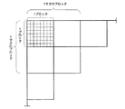
MPEG方式にて圧縮または伸張処理された原画像は、離散コサイン変換または逆離散コサイン変換時に、8画素×8画素の大きさの1ブロック単位で処理されている。この場合は、前記単位エリアを前記1ブロックと一致させればよい。
従って、1フレーム中の水平及び垂直方向にて、(n×8)番目の画素と、(n×8+1)番目の画素が境界画素となる。ただし、nは自然数である。
【0015】
MPEG方式にて圧縮または伸張処理された原画像は、動き補償または逆動き補償の処理時に、16画素×16画素の大きさの1マクロブロック単位で処理されている。よって、前記単位エリアを1マクロブロックと一致させてもよい。この場合は、1フレーム中の水平及び垂直方向にて、(n×16)番目の画素と、(n×16+1)番目の画素が境界画素となる。
【0016】
前記データの補間を実施する工程は、補間画素のデータを、補間画素と隣接する複数画素の各データを用いて平均化する工程を含むことができる。あるいは、前記データの間引きを実施する工程は、間引画素に隣接する画素のデータであって、前記複数の第1または第2の境界画素以外のデータを、間引画素のデータを用いて平均化する工程を含むことができる。こうすると、平均化しない場合と比較して、輝度または色強調が緩和されて、原画像に近い画質を維持することができる。
【0017】
なお、前記原画像がカラー画像の場合、RGB成分の画像をサイズ変更しても良いが、YUV成分から成るカラー画像を対象としても良い。後者の場合、前記平均化工程は、色に対する感覚が支配的なY成分についてのみ実施されてもよい。
【0018】
ここで、本発明の他の態様に係る画像サイズの変更装置では、前記画像サイズ変更手段は、前記水平方向にて前記画像サイズを変更する水平方向変更手段と、前記垂直方向にて前記画像サイズを変更する垂直方向変更手段とを有することができる。
【0019】
この場合、前記水平及び垂直方向変更手段の少なくとも一方は、前記水平または垂直方向でn(nは自然数)番目の画素のデータが入力される第1の水平バッファと、前記水平または垂直方向で(n+1)番目の画素のデータが入力される第2の水平バッファと、前記n番目及び(n+1)番目の各画素のデータを平均化する演算部と、前記演算部の出力が入力される第3の水平バッファと、前記第1〜第3のバッファの出力のいずれか一つを選択するセレクタとを有することができる。
【0020】
前記倍率が拡大倍率の時には、前記セレクタは、前記補間画素に対して、前記第3の水平バッファの出力を選択して出力すればよい。一方、前記倍率が縮小倍率の時には、前記間引き画素に隣接する画素に対して、前記第3の水平バッファの出力を選択して出力すればよい。
【0021】
【発明の実施の形態】
以下、本発明の一実施形態について、図面を参照して説明する。
【0022】
(携帯電話機の概要)
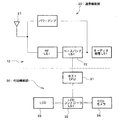
図1は、本発明が適用される電子機器の一例である携帯電話機のブロック図である。図1において、この携帯電話機10は、通信機能部20と付加機能部30とに大別される。通信機能部20は、アンテナ21にて送受信される信号(圧縮動画像を含む)を処理する公知の各種ブロックを有する。通信機能部20の全ブロックの説明は省略するが、ベースバンドLSI22は、主として音声などを処理するプロセッサであり、携帯電話10には必ず搭載されている。このベースバンドLSI22には、ベースバンドエンジン(BBE)やアプリーションプロセッサ等が搭載されている。これらのプロセッサ上のソフトウェアにより、図2(A)に示すMPEG4の圧縮(エンコード)処理のうち、可変長符号(VLC:Variable Length Code)への符号化(Encode)、スキャン(Scan)、ACDC(交流・直流成分)予測及びレートコントロール(Rate Control)が実施されるようになっている。さらに、ベースバンドLSI22に搭載されたプロセッサ上のソフトウェアにより、図2(B)に示すMPEG4の伸張(デコード)処理のうち、可変長符号(VLC)の復号(Decode)、逆スキャン(Reverse Scan)及び逆ACDC(交流・直流成分)予測が実施されるようになっている。MPEG4のデコード及びエンコードの他の処理については、付加機能部30に設けられたハードウェアにて実施される。
【0023】
付加機能部30は、通信機能部20のベースバンドLSI21に接続されたホストCPU(中央演算ユニット)31を有する。このホストCPU31にはLCDコントローラLSI32が接続されている。このLCDコントローラLSI32には、画像表示部としての液晶表示装置(LCD)33と、撮像部としてのCCDカメラ34とが接続されている。MPEG4のデコード及びエンコードのうちのハードウェア処理と、画像サイズの変更のためのハードウェア処理とについては、LCDコントローラLSI32に設けられたハードウェアにて実施される。
【0024】
(MPEG4のエンコード及びデコード)
ここで、図2(A)及び図2(B)に示すMPEG4のエンコード及びデコードの各処理について簡単に説明する。この処理の詳細については、例えば日本実業出版社の「JPEG&MPEG 図解でわかる画像圧縮技術」(越智宏、黒田英夫の共著)に説明されているので、本発明に関する処理についてのみ主として説明する。
【0025】
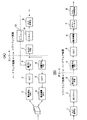
図2(A)に示す圧縮(エンコード)処理では、まず、連続する2枚の画像間の動き検出(ME:Motion Estimation)が実施される(ステップ1)。具体的には2枚の画像間の同一画素同士の差分を求める。2枚の画像での静止画領域では差分が0になるので、情報量を少なくでき、この静止画領域のゼロデータに加え、動画領域の差分(プラス・マイナス成分)が動き検出後の情報となる。
【0026】
次に、離散コサイン変換(DCT:Discrete Cosine Transform)が実施される(ステップ2)。この離散コサイン変換(DCT)は、図3に示す8画素×8画素の1ブロック単位にて演算され、1ブロック毎にDCT係数を求めるものである。離散コサイン変換後のDCT係数は、1ブロック内の画像の濃淡変化を、全体の明るさ(DC成分)と空間周波数(AC成分)とで表わしたものである。図4は、8×8画素の1ブロック内のDCT係数の一例を示している(上述の図書の第116頁の図5−6を引用)。その左上隅のDCT係数がDC成分を示し、それ以外のDCT係数がAC成分を示す。なお、AC成分のうち、高周波成分を省略しても画像認識への影響が少ない。
【0027】
次に、DCT係数の量子化が行われる(ステップ3)。この量子化は、1ブロック内の各DCT係数を、量子化テーブル中の対応する位置の量子化ステップ値で除算して、情報量を少なくするために実施される。例えば、図4のDCT係数を図5の量子化テーブルを用いて量子化した1ブロック内のDCT係数を図6に示す(上述の図書の第117頁の図5−9及び図5−10を引用)。図6に示す通り、特に、高周波成分のDCT係数を量子化ステップ値で除算し、その小数点以下を四捨五入すると、ほとんどがゼロデータとなり、情報量が大幅に減少している。
【0028】
このエンコード処理には、処理フレームと次フレームとの間で上述の動き検出(ME)を実施するために、帰還ルートが必要となる。この帰還ルートでは、図2(A)に示すように、逆量子化(iQ)、逆DCT及び動き補償(MC:Motion Compensation)が実施される(ステップ4〜6)。なお、動き補償の詳細な動作については省略するが、この処理は図3に示す16画素×16画素の1マクロブロック単位で実施される。
【0029】
上述したステップ1〜6の処理は、本実施形態のLCDコントローラLSI32に設けられたハードウェアにて実施される。
【0030】
次に、図1のベースバンドLSI22に搭載されたプロセッサ上のソフトウェアにより実施されるACDC(交流・直流成分)予測、スキャン(Scan)、可変長符号(VLC:Variable Length Code)への符号化(Encode)及びレートコントロール(Rate Control)について説明する。
【0031】
図2(A)のステップ7で実施されるACDC(交流・直流成分)予測及びステップ8で実施されるスキャンは、共にステップ9の可変長符号の符号化に必要な処理である。なぜなら、ステップ9の可変長符号への符号化は、DC成分については隣接ブロック間での差分を符号化し、AC成分についてはブロック内を周波数が低い側から高い側に向けてスキャン(ジグザグスキャンとも称する)して符号化の順序を決める必要があるからである。
【0032】
ステップ9の可変長符号への符号化とは、エントロピー符号化とも称され、符号化原理として、出現頻度の多いものは少ない符号で表すように符号化するものである。ステップ7,8での結果を利用して、DC成分について隣接ブロック間での差分を符号化し、AC成分についてはスキャンされた順番で低周波側から高周波側から順にDCT係数値を符号化する。
【0033】
ここで、画像信号は、その画像の複雑さや動きの激しさによって情報の発生量が変動する。この変動を吸収し、一定の伝送速度で伝送するには符号発生量の制御が必要であり、これがステップ10のレートコントロールである。レートコントロールのために通常バッファメモリが設けられ、そのバッファメモリがオーバフローしないように蓄積情報量を監視し、情報発生量を抑えるようにする。具体的には、ステップ3での量子化特性を粗くして、DCT係数値を表すビット数を減らしている。
【0034】
図2(B)は圧縮された動画像の伸張(デコード)処理を示し、このデコード処理は図2(A)のエンコード処理を逆順でかつ逆処理することで達成される。
なお、図2(B)中の「ポストフィルタ」とは、ブロックノイズを消去するためのフィルタである。このデコード処理でも、VLC復号化(ステップ1)、逆スキャン(ステップ2)及び逆ACDC予測(ステップ3)がソフトウェア処理され、逆量子化以降の処理がハードウェア処理される(ステップ4〜8)。
【0035】
(圧縮画像の伸張のための構成及び動作)
図7は、図1に示すLCDコントローラLSI32の機能ブロック図である。
なお、図7は圧縮動画像のデコード処理部と画像サイズの変更部に関係するハードウェアを示している。このLCDコントローラLSI32は、図2(B)のステップ4〜8を実施する第1のハードウェア処理部40、データ記憶部50及び画像サイズを変更する第2のハードウェア処理部80を有する。この第2のハードウェア処理部80は、水平方向サイズ変更部81および垂直方向サイズ変更部82を有する。また、このLCDコントローラLSI32は、ホストインターフェース60を介してホストCPU31に接続される。ベースバンドLSI22内にはソフトウェア処理部70が設けられる。このソフトウェア処理部70は、図2(B)のステップ1〜3を実施する。このソフトウェア処理部70もまた、ホストCPU31に接続されている。
【0036】
まず、ソフトウェア処理部70について説明する。このソフトウェア処理部70は、ハードウェアとしてCPU71と画像処理プログラム格納部72とを有する。CPU71は、格納部72に格納された画像処理プログラムに従って、図1のアンテナ21から入力された圧縮動画像に対して、図2(B)に示すステップ1〜3を実施する。CPU71はさらに、図2(B)のステップ3の処理済データを圧縮するデータ圧縮部71Aとして機能する。圧縮されたデータは、ホストCPU31、ホストインターフェース60を介して、LCDコントローラ32内のデータ記憶部50(例えばSRAMなど)に設けられた圧縮データ用記憶領域51に格納される。
【0037】
一方、LCDコントローラ32内に設けられた第1のハードウェア処理部40は、圧縮データ用記憶領域51からの圧縮データを伸張するデータ伸張部41を有する。この第1のハードウェア処理部40には、図2(B)のステップ4〜7の各処理を実施するための処理部42〜45が設けられている。ポストフィルタ45にてブロックノイズが除去された動画像データは、データ記憶部50内の表示用記憶領域52内に格納される。色情報変換処理部46は、表示用記憶領域52内に格納された画像情報に基づいて、図2(B)のステップ8のYUV/RGB変換を実施する。処理部46の出力は、LCDインターフェース47を介してLCD33に供給され、表示駆動に供される。なお、表示用記憶領域52は、少なくとも1フレーム分の動画像を記憶する容量を有する。表示用記憶領域52は、好ましくは2フレーム分の動画像を記憶する容量を有し、動画像をより円滑に表示できるようにしても良い。
【0038】
(画像サイズ変更の原理)
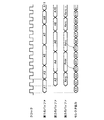
次に、画像サイズを変更する第2のハードウェア処理部80での画像サイズの変更原理について、図8及び図9を参照して説明する。図8は原画像サイズを1.25倍に拡大し、図9は原画像サイズを0.75倍に縮小する動作原理をそれぞれ示している。
【0039】
図8に示すように、原画像サイズを縦横1.25倍に拡大するには、8×8画素の1ブロックを、10×10画素に拡大すればよい。このために、図8に示すように、1ブロック内の縦横の各々で、1〜8番目の画素のうち2つの画素のデータを2つの補間画素100のデータとして繰り返し用いればよい(画素ダブリングと称する)。
【0040】
一方、原画像サイズを縦横0.75倍に縮小するには、図9に示すように、1ブロック内の縦横の各々で、1〜8番目の画素のうち2つの画素を間引き画素110として間引いて、2画素分のデータを欠落させればよい。
【0041】
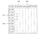
ここで、本実施形態では、原画像の各1ブロック(単位エリア)は、図8及び図9に示すように、1フレームの水平方向で隣接する2つのブロック間の垂直仮想境界線VVBLに沿って配列された複数の第1の境界画素120を含んでいる。同様に、1フレームの垂直方向で隣接する2つのブロック間の水平仮想境界線HVBLに沿って配列された複数の第2の境界画素130を含んでいる。
【0042】
拡大画像を示す図8の画像の水平方向では、複数の第1の境界画素120を含まない画素間に、2つの水平補間画素100A,100Bを設定する。図8では、原画像の1ブロック内にて、水平方向で2番目(例えばA2)と3番目(例えばA3)との間に第1の水平補間画素100Aが、水平・垂直方向で6番目(例えばA6)と7番目(例えばA7)との間に第2の水平補間画素100Bが設けられている。図8では、第1,第2の水平補間画素100A,100Bの各データは、水平方向で2番目(例えばA2)または6番目(例えばA6)の画素のデータをダブリングすることで形成されている。
【0043】
拡大画像を示す図8の画像の垂直方向では、複数の第2の境界画素130を含まない画素間に、2つの垂直補間画素100C,100Dを設定する。図8では、原画像の1ブロック内にて、垂直方向で3番目(例えばC1)と4番目(例えばD1)との間に第1の垂直補間画素100Cが、垂直方向で5番目(例えばE1)と6番目(例えばF1)との間に第2の垂直補間画素100Dが設けられている。図8では、第1,第2の垂直補間画素100C,100Dの各データは、垂直方向で3番目(例えばC1)または5番目(例えばE1)の画素のデータをダブリングすることで形成されている。
【0044】
一方、縮小画像を示す図9の画像の水平方向では、複数の第1の境界画素120以外の位置に指定された2つの水平間引き画素110A,110Bが間引かれている。図9では、原画像の1ブロック内にて、水平方向で3番目(A3,B3,…H3)の第1の水平間引き画素110Aと、水平方向で6番目(A6,B6,…H6)の第2の水平間引き画素110Bとがそれぞれ間引かれている。
【0045】
縮小画像を示す図9の画像の垂直方向では、複数の第2の境界画素130以外の位置に指定された2つの垂直間引き画素110C,110Dが間引かれている。図9では、原画像の1ブロック内にて、垂直方向で3番目(C1,C2,…C8)の第1の垂直間引き画素110Cと、垂直方向で6番目(F1,F2,…F8)に第2の垂直間引き画素110Dとがそれぞれ間引かれている。
【0046】
ここで、原画像を水平方向で拡大・縮小する時に、第1の境界画素120のデータを用いて補間し、あるいは第1の境界画素120を間引くと、2つの単位エリアの境界が強調処理され、垂直仮想境界線VVBLが画面上で目立つようになってしまう。本実施形態では、第1の境界画素120のデータが補間データとされたり間引かれたりすることを禁止しているので、画像サイズを水平方向にて拡大・縮小しても画質を維持することができる。
【0047】
同様に、原画像を垂直方向で拡大・縮小する時に、第2の境界画素130のデータを用いて補間し、あるいは第2の境界画素130を間引くと、2つの単位エリアの境界が強調処理され、水平仮想境界線HVBLが画面上で目立つようになってしまう。本実施形態では、第2の境界画素130のデータが補間データとされたり間引かれたりすることを禁止しているので、画像サイズを垂直方向にて拡大・縮小しても画質を維持することができる。
【0048】
図10及び図11は、図8及び図9にさらに、データ平均化の手法を取り入れた時の拡大・縮小動作を示している。図10では、補間画素100A〜100Dが、その前後の画素を平均化したデータとされている。
【0049】
ここで、拡大画像の1ブロックの水平方向で例えば第3,5列目の画素データA3,A4間にある補間画素データAA34とは、AA34=(A3+A4)/2の意味である。同様に、1ブロックの垂直方向で例えば第3,5行目の画素データC1,D1間にある補間画素データADC1とは、ACD1=(C1+D1)/2の意味である。
【0050】
このように、補間画素データをその両隣の画素データにて平均化することで、図8のように画素データをダブリングさせたものと比較すれば、輝度または色強調が緩和される。特に、輪郭部などにて色または輝度が激しく変化する部分について、その変化が滑らかになって原画像の画質を維持できる。
【0051】
一方、図9にて間引き画素の隣にある画素は、図11に示すように平均化される。例えば、図9の間引き画素データA3の左隣にある画素データA4は、図11では間引き画素データA3を用いて画素データAA34に平均化されている。
この画素データAA34とは、AA34=(A3+A4)/2の意味である。縮小画像において間引き画素データを用いて残存画素データを平均化することで、拡大画像と同じく、原画像の画質を維持できる。
【0052】
(第2のハードウェア処理部の構成及び動作)
図12は、図7に示す第2のハードウェア処理部80内に設けられた、水平方向サイズ変更部81及び垂直方向サイズ変更部82の一方または双方に設けられる構成を示すブロック図である。
【0053】
図12において、第1のバッファ90には、図7の表示用記憶領域52より水平または垂直方向でn(nは自然数)番目の画素のデータが入力される。第2のバッファ91には、図7の表示用記憶領域52より水平または垂直方向で(n+1)番目の画素のデータが入力される。演算部92は、n番目及び(n+1)番目の各画素のデータを平均化する。第3のバッファ93には、演算部92の出力が入力される。セレクタ94は、第1〜第3のバッファ90,91,93の出力のいずれか一つを選択する。セレクタ94の出力は、図7の表示用記憶領域52内の所定のアドレスに記憶される。これらの各ブロック90〜94は、クロック生成部95からのクロックに同期して動作するようになっている。
【0054】
図12に示すサイズ変更部の基本的動作を図13を参照して説明する。図13は、そのセレクタ出力の通り、1ブロック内にて3番目と4番目の画素データA3,A4間に補間画素データAA34を補間して拡大する場合の動作を示している(拡大倍率9/8)。
【0055】
図13に示すように、第1〜第3のバッファ90,91,93には、原則として2クロック分の時間だけデータが書き込まれ、セレクタ94は1クロックに1回、第1〜第3のバッファ90,91,93のいずれかの出力を選択して出力する。
【0056】
具体的には、先ず画素データA1が第1のバッファ90に書き込まれ、次の画素データA2が演算部92に入力されると同時に、第1のバッファ90からの画素データA1が演算部92に入力される。演算部92では、AA12=(A1+A2)/2の平均化を行う。この平均化データAA12は、2番目のクロックに従って画素データA2が第2のバッファ91に書き込まれると同時に、第3のバッファ93に書き込まれる。以下、画素データは交互に第1,第2のバッファ90,91に書き込まれ、同様の動作が繰り返される。
【0057】
セレクタ94は、最初のクロックに従って第1のバッファ90に書き込まれた画素データA1を選択して出力する。次のクロックでは、第2のバッファ91からの画素データA2を選択する。3番目のクロックでは、第1のバッファ90からの画素データA3を選択する。次に補間画素のデータとして、第3のバッファ93からの平均化データAA34を選択する。以降、各ブロック毎に同じ動作を繰り返す。
【0058】
ここで、補間画素データを1回選択すると、以降のクロック同期を修正する必要があり、図13では省略しているが、画素データA12,A13については例外的に3クロック分だけ対応するバッファに書き込んでおく必要がある。
【0059】
この例外的動作を利用して、図10に示す1.25倍の拡大画像を生成する場合について、図14を参照して説明する。
【0060】
図14では、図10にて説明した通り、1ブロックの例えば水平方向にて2つの補間画素100A,110BのデータAA34,AA56を生成する必要がある。このために、画素データA4〜A7及び平均化データAA34,AA56については、対応するバッファに3クロック分の時間だけ格納される。画素データA5を2クロック分だけ格納すると、平均化データAA56を生成する時に画素データA5がバッファ内に存在しなくなってしまうからである。他の一部の画素データも、タイミング合わせのために、3クロック分だけ対応するバッファに格納される。
【0061】
図15は、図11に示す0.75倍の縮小画像を生成する場合の動作を示している。この場合、原則通り、各バッファ90,91,93には2クロック分の時間だけデータが格納されればよい。ただし、図15に示すように、セレクタ94から平均化データAA34を選択した後、1クロック分待機した後に、次の画素データを選択するようにしている。
【0062】
ここで、本実施形態では、図7に示す通り、YUV成分から成るカラー画像を原画像として、そのサイズを拡大または縮小しようとしている。図7では、LCD33に出力する前にRGBへの変換を実施しているからである。もちろん、RGB画像を原画像としてもよい。
【0063】
ここで、YUV成分の原画像の場合、Y成分がU,V成分に比べ色に対する感覚を大きく支配する。そこで、Y成分についてのみ、図10に示すように補間画素データを平均化し、U,V成分については補間画素について平均化せずに、図8に示すように先行画素をダブリングするだけでも良い。このようにすると、平均化のための演算対象が減少するので、より高速処理が可能となる。
【0064】
なお、本発明は上述した実施形態に限定されるものではなく、本発明の要旨の範囲内で種々の変形実施が可能である。本発明が適用される電子機器は携帯電話機に限定されず、他の電子機器特に携帯機器に好適に適用できる。また、原画像の処理履歴である圧縮・伸張手法についてはMPEG4方式に限定されず、単位エリア毎の処理を含む他の圧縮・伸張方式であっても良い。また、上述した実施形態では、横拡大倍率=縦拡大倍率=1.25、横縮小倍率=縦縮小倍率=0.75としたが、これは一例に過ぎず、機器にて設定可能な種々の倍率に適用でき、必ずしも縦・横で拡大または縮小倍率を一致させる必要もない。
【0065】
また、例えば1.25倍に拡大する際に、1ブロック内の原画像中の画素(12345678)に対して、1223456778、1233456678など、補間画素の設定箇所は境界画素以外であれば任意に設定できる。例えば0.75倍に縮小する時も、124578、134568など、間引き画素の設定箇所は境界画素以外であれば任意に設定できる。
【図面の簡単な説明】
【図1】 本発明が適用される電子機器の一例である携帯電話機の概略ブロック図である。
【図2】 図2(A)はMPEGエンコーダでの処理手順を、図2(B)はMPEGデコーダでの処理手順をそれぞれ示すフローチャートである。
【図3】 MPEGエンコーダ、デコーダでの処理単位である1ブロック及び1マクロブロックを示す図である。
【図4】 離散コサイン変換(DCT)にて得られるDCT係数の一例を示す図である。
【図5】 量子化の際に用いられる量子化テーブルの一例を示す図である。
【図6】 図4のDCT係数を図5の量子化テーブル中の数値にて除算して得られる量子化されたDCT係数(QFデータ)を示す図である。
【図7】 図1中の部材のうち、MPEGデコーダに関する構成を説明するためのブロック図である。
【図8】 拡大倍率を1.25倍とした時の動作を説明するための図である。
【図9】 縮小倍率を0.75倍とした時の状態を説明するための図である。
【図10】 図10中の補間画素データを平均化した拡大画像を示す図である。
【図11】 図11中の間引き画素のデータにより残存画素を平均化した縮小画像を示す図である。
【図12】 図7中の水平・垂直方向サイズ変更部の一例を示すブロック図である。
【図13】 図12に示す回路の基本動作を示すタイミングチャートである。
【図14】 図12の回路を用いて図10に示す拡大画像のデータを生成する動作を示すタイミングチャートである。
【図15】 図12の回路を用いて図11に示す縮小画像のデータを生成する動作を示すタイミングチャートである。
【符号の説明】
10 携帯電話機、 20 通信機能部、 21 アンテナ、 22 ベースバンドLSI、 30 付加機能部、 31 ホストCPU、 32 LCDコントローラ、 33 LCD(画像表示部)、 34 CCDカメラ(撮像部)、40 第1のハードウェア処理部、 41 データ伸張部、 42 逆量子化部、 43 逆DCT処理部、 44 動き補償処理部、 45 ポストフィルタ、 46 色情報変換処理部、 47 LCDインターフェース、50 データ記憶部、 51 圧縮データ用記憶領域、 51A 第1のフレームメモリ、51B 第2のフレームメモリ、 52 表示用記憶領域、 60 ホストインターフェース、 70 ソフトウェア処理部、 71 CPU、 71A データ圧縮部、 72 画像処理プログラム格納部、 80 第2のハードウェアブロック、 81 水平方向サイズ変更部、 82 垂直方向サイズ変更部、 90 第1のバッファ、 91 第2のバッファ、 92 演算部、 93 第3のバッファ、 94 セレクタ、 95 クロック生成部、 100A,100B 水平補間画素、 100C,100D 垂直補間画素、 110A,110B 水平間引き画素、 110C,110D 垂直間引き画素、 120 第1の境界画素、 130 第2の境界画素、 VVBL 垂直仮想境界線、 HVBL 水平仮想境界線[0001]
BACKGROUND OF THE INVENTION
The present invention relates to an image size changing method and apparatus for changing the size of an original image having a processing history compressed or expanded by, for example, MPEG (Motion Picture Coding Experts Group).
[0002]
[Background Art and Problems to be Solved by the Invention]
Conventionally, in order to enlarge the image size, data is interpolated to interpolated pixels between certain pixels, and in order to reduce the image size, data of thinned pixels is lost.
[0003]
However, when this method is applied to an image having a processing history compressed or expanded by MPEG4, for example, there is a problem that the screen flickers or the roughness becomes conspicuous and the image quality deteriorates.
[0004]
The present inventors have found that the cause of the deterioration of the image quality is related to the processing for each unit area obtained by dividing one frame into a plurality during compression or decompression processing.
[0005]
Accordingly, an object of the present invention is to provide an image size changing method and apparatus capable of enlarging or reducing an original image having a processing history compressed or expanded for each unit area without degrading image quality. is there.
[0006]
[Means for Solving the Problems]
According to one aspect of the present invention, there is provided a method for changing an image size, the step of storing an original image processed for each unit area obtained by dividing one frame into a plurality of frames, and the original image according to a set horizontal enlargement magnification. Interpolating data to interpolated pixels between predetermined pixels in each unit area, and enlarging and changing at least the horizontal size of the original image. Each unit area of the original image includes a plurality of first boundary pixels arranged along a vertical virtual boundary line between two unit areas adjacent in the horizontal direction of the one frame. In the image size changing step, the interpolation pixel is set between pixels not including the plurality of first boundary pixels. Another aspect of the invention defines an apparatus for performing this method.
[0007]
An original image to be processed by the method and apparatus of the present invention has a processing history processed for each unit area obtained by dividing one frame into a plurality of frames. Each unit area is adjacent to another unit area in the horizontal direction or vertical method in one frame. In two unit areas adjacent in the horizontal direction, the first boundary pixel in one unit area and the first boundary pixel in the other unit area arranged along a vertical virtual boundary line between them are: Since the processing units are different, the data correlation is relatively small even between adjacent pixels.
[0008]
Therefore, when the data of the first boundary pixel is used as the interpolation data for the interpolation pixel, the boundary between the two unit areas is emphasized, and the vertical virtual boundary line becomes conspicuous on the screen.
[0009]
In the present invention, since the data of the first boundary pixel is prohibited from being used as interpolation data, the image quality can be maintained even if the image size is expanded in the horizontal direction.
[0010]
The present invention can also be applied when an original image is enlarged in the vertical direction. In this case, each unit area of the original image includes a plurality of second boundary pixels arranged along a horizontal virtual boundary line between two unit areas adjacent in the vertical direction of the one frame. . Then, the image size changing step sets the interpolation pixel between pixels not including the plurality of second boundary pixels according to the set vertical enlargement magnification. Thus, since the data of the second boundary pixel is prohibited from being used as interpolation data, the image quality can be maintained even if the image size is enlarged in the vertical direction.
[0011]
The present invention can also be applied when an original image is reduced in the horizontal direction. In this case, the image size changing step thins out data of thinned pixels other than the plurality of first boundary pixels in each unit area of the original image according to the set horizontal reduction ratio, Reduce the horizontal size to change. Thus, since the data of the first boundary pixel is prohibited from being thinned out, the image quality can be maintained even if the image size is reduced in the horizontal direction.
[0012]
The present invention can also be applied when reducing an original image in the vertical direction. In this case, the image size changing step thins out data of thinned pixels other than the plurality of second boundary pixels in each unit area of the original image according to the set vertical reduction ratio, Reduce the vertical size to change. Thus, since the data of the second boundary pixel is prohibited from being thinned out, the image quality can be maintained even if the image size is reduced in the vertical direction.
[0013]
As an original image having a processing history processed for each unit area, for example, an image compressed or expanded by the MPEG method can be cited.
[0014]
An original image compressed or expanded by the MPEG method is processed in units of one block having a size of 8 pixels × 8 pixels at the time of discrete cosine transform or inverse discrete cosine transform. In this case, the unit area may be matched with the one block.
Accordingly, the (n × 8) th pixel and the (n × 8 + 1) th pixel are boundary pixels in the horizontal and vertical directions in one frame. However, n is a natural number.
[0015]
An original image compressed or expanded by the MPEG method is processed in units of one macroblock having a size of 16 pixels × 16 pixels at the time of motion compensation or inverse motion compensation processing. Therefore, the unit area may be matched with one macroblock. In this case, the (n × 16) th pixel and the (n × 16 + 1) th pixel are boundary pixels in the horizontal and vertical directions in one frame.
[0016]
The step of performing the interpolation of the data may include a step of averaging the data of the interpolation pixel using each data of a plurality of pixels adjacent to the interpolation pixel. Alternatively, the step of thinning out the data may be data of pixels adjacent to the thinned pixels, and data other than the plurality of first or second boundary pixels may be averaged using the thinned pixel data. The process of comprising can be included. In this way, brightness or color enhancement is relaxed compared to the case where averaging is not performed, and image quality close to the original image can be maintained.
[0017]
When the original image is a color image, the RGB component image may be resized, but a color image composed of YUV components may be used as a target. In the latter case, the averaging step may be performed only for the Y component in which the sense of color is dominant.
[0018]
Here, in the image size changing device according to another aspect of the present invention, the image size changing means includes a horizontal direction changing means for changing the image size in the horizontal direction, and the image size in the vertical direction. And vertical direction changing means for changing.
[0019]
In this case, at least one of the horizontal and vertical direction changing means includes a first horizontal buffer to which data of an n-th pixel (n is a natural number) is input in the horizontal or vertical direction, and the horizontal or vertical direction ( a second horizontal buffer to which the data of the (n + 1) th pixel is input, an arithmetic unit for averaging the data of the nth and (n + 1) th pixels, and a third input of the output of the arithmetic unit. Horizontal buffers and a selector for selecting any one of the outputs of the first to third buffers.
[0020]
When the magnification is an enlargement magnification, the selector may select and output the output of the third horizontal buffer for the interpolation pixel. On the other hand, when the magnification is the reduction magnification, the output of the third horizontal buffer may be selected and output for the pixels adjacent to the thinned pixels.
[0021]
DETAILED DESCRIPTION OF THE INVENTION
Hereinafter, an embodiment of the present invention will be described with reference to the drawings.
[0022]
(Outline of mobile phone)
FIG. 1 is a block diagram of a mobile phone as an example of an electronic apparatus to which the present invention is applied. In FIG. 1, the
[0023]
The
[0024]
(MPEG4 encoding and decoding)
Here, the MPEG4 encoding and decoding processes shown in FIGS. 2A and 2B will be briefly described. Details of this processing are described in, for example, “Image compression technology understood by JPEG & MPEG” (co-authored by Tomohiro Koshi and Hideo Kuroda) of Nippon Jitsugyo Publishing Co., Ltd. Therefore, only the processing relating to the present invention will be mainly described.
[0025]
In the compression (encoding) process shown in FIG. 2A, first, motion estimation (ME: Motion Estimation) between two consecutive images is performed (step 1). Specifically, the difference between the same pixels between two images is obtained. Since the difference is 0 in the still image area between the two images, the amount of information can be reduced. In addition to the zero data of the still image area, the difference (plus / minus component) of the moving image area is the information after the motion detection. Become.
[0026]
Next, a discrete cosine transform (DCT) is performed (step 2). This discrete cosine transform (DCT) is calculated for each block of 8 pixels × 8 pixels shown in FIG. 3, and obtains a DCT coefficient for each block. The DCT coefficient after the discrete cosine transform represents the change in lightness and darkness of an image in one block by the overall brightness (DC component) and the spatial frequency (AC component). FIG. 4 shows an example of DCT coefficients in one block of 8 × 8 pixels (refer to FIG. 5-6 on page 116 of the above-mentioned book). The DCT coefficient in the upper left corner indicates the DC component, and the other DCT coefficients indicate the AC component. Note that even if the high-frequency component is omitted from the AC component, the influence on the image recognition is small.
[0027]
Next, the DCT coefficient is quantized (step 3). This quantization is performed in order to reduce the amount of information by dividing each DCT coefficient in one block by the quantization step value at the corresponding position in the quantization table. For example, FIG. 6 shows DCT coefficients in one block obtained by quantizing the DCT coefficients of FIG. 4 using the quantization table of FIG. 5 (see FIGS. 5-9 and 5-10 on page 117 of the above-mentioned book). Quote). As shown in FIG. 6, in particular, when the DCT coefficient of the high frequency component is divided by the quantization step value and rounded off after the decimal point, most of the data becomes zero data, and the amount of information is greatly reduced.
[0028]
This encoding process requires a return route in order to perform the above-described motion detection (ME) between the processing frame and the next frame. In this feedback route, as shown in FIG. 2A, inverse quantization (iQ), inverse DCT, and motion compensation (MC) are performed (
[0029]
The processes in
[0030]
Next, ACDC (AC / DC component) prediction, scan, and encoding into a variable length code (VLC) (VLC: Variable Length Code) implemented by software on a processor mounted on the
[0031]
The ACDC (alternating current / direct current component) prediction performed in
[0032]
The encoding to the variable length code in
[0033]
Here, the amount of information generated in the image signal varies depending on the complexity of the image and the intensity of movement. In order to absorb this variation and transmit at a constant transmission rate, it is necessary to control the amount of generated code. This is the rate control in
[0034]
FIG. 2B shows decompression (decoding) processing of a compressed moving image, and this decoding processing is achieved by performing the reverse processing and the reverse processing of the encoding processing of FIG.
Note that the “post filter” in FIG. 2B is a filter for eliminating block noise. Also in this decoding process, VLC decoding (step 1), inverse scan (step 2), and inverse ACDC prediction (step 3) are processed by software, and the processes after inverse quantization are processed by hardware (
[0035]
(Configuration and operation for decompressing compressed images)
FIG. 7 is a functional block diagram of the
FIG. 7 shows hardware related to a compressed moving image decoding processing unit and an image size changing unit. The
[0036]
First, the
[0037]
On the other hand, the first
[0038]
(Principle of image size change)
Next, the principle of changing the image size in the second
[0039]
As shown in FIG. 8, in order to enlarge the original image size by 1.25 times in the vertical and horizontal directions, one block of 8 × 8 pixels may be enlarged to 10 × 10 pixels. For this purpose, as shown in FIG. 8, in each of the vertical and horizontal directions in one block, data of two pixels among the first to eighth pixels may be repeatedly used as data of two interpolation pixels 100 (pixel doubling and Called).
[0040]
On the other hand, in order to reduce the original image size by 0.75 times in the vertical and horizontal directions, as shown in FIG. 9, two out of the first to eighth pixels are thinned out as the thinned
[0041]
Here, in this embodiment, each block (unit area) of the original image is along a vertical virtual boundary line VVBL between two adjacent blocks in the horizontal direction of one frame, as shown in FIGS. The plurality of
[0042]
In the horizontal direction of the image of FIG. 8 showing the enlarged image, two
[0043]
In the vertical direction of the image of FIG. 8 showing the enlarged image, two
[0044]
On the other hand, in the horizontal direction of the image of FIG. 9 showing the reduced image, two horizontal thinned
[0045]
In the vertical direction of the image of FIG. 9 showing the reduced image, two vertically thinned pixels 110C and 110D designated at positions other than the plurality of
[0046]
Here, when the original image is enlarged or reduced in the horizontal direction, if the
[0047]
Similarly, when the original image is enlarged / reduced in the vertical direction, if the interpolation is performed using the data of the
[0048]
FIG. 10 and FIG. 11 show the enlargement / reduction operation when the data averaging method is further adopted in FIG. 8 and FIG. In FIG. 10 , the
[0049]
Here, for example, the interpolation pixel data A A34 between the pixel data A3 and A4 in the third and fifth columns in the horizontal direction of one block of the enlarged image means A A34 = (A3 + A4) / 2. Similarly, the interpolated pixel data ADC1 between, for example, the pixel data C1 and D1 in the third and fifth rows in the vertical direction of one block means A CD1 = (C1 + D1) / 2.
[0050]
In this way, by averaging the interpolated pixel data with the pixel data on both sides thereof, the luminance or color enhancement is alleviated as compared with the pixel data doubled as shown in FIG. In particular, in a portion where the color or luminance changes drastically in the contour portion or the like, the change becomes smooth and the image quality of the original image can be maintained.
[0051]
On the other hand, the pixels adjacent to the thinned pixels in FIG. 9 are averaged as shown in FIG. For example, the pixel data A4 on the left side of the thinned pixel data A3 in FIG. 9 is averaged to the pixel data AA34 using the thinned pixel data A3 in FIG.
The pixel data A A34 means A A34 = (A3 + A4) / 2. By averaging the remaining pixel data using the thinned pixel data in the reduced image, the image quality of the original image can be maintained as in the enlarged image.
[0052]
(Configuration and operation of second hardware processing unit)
FIG. 12 is a block diagram showing a configuration provided in one or both of the horizontal direction
[0053]
In FIG. 12, the
[0054]
The basic operation of the size changing unit shown in FIG. 12 will be described with reference to FIG. FIG. 13 shows the operation when the interpolation pixel data AA34 is interpolated and enlarged between the third and fourth pixel data A3 and A4 in one block as shown in the selector output (
[0055]
As shown in FIG. 13, in principle, data is written in the first to
[0056]
Specifically, the pixel data A1 is first written to the
[0057]
The
[0058]
Here, when the interpolation pixel data is selected once, it is necessary to correct the subsequent clock synchronization. Although omitted in FIG. 13, the pixel data A12 and A13 are exceptionally buffered corresponding to three clocks. It is necessary to write it down.
[0059]
A case where a magnified image of 1.25 times shown in FIG. 10 is generated using this exceptional operation will be described with reference to FIG.
[0060]
In FIG. 14, as described with reference to FIG. 10, it is necessary to generate data A A34 and A A56 of two
[0061]
FIG. 15 shows an operation when generating a 0.75 times reduced image shown in FIG. In this case, as a general rule, each
[0062]
Here, in this embodiment, as shown in FIG. 7, a color image composed of YUV components is used as an original image, and the size is to be enlarged or reduced. This is because the conversion to RGB is performed before outputting to the
[0063]
Here, in the case of the original image of the YUV component, the Y component largely dominates the sense of color compared to the U and V components. Therefore, for the Y component only, the interpolation pixel data may be averaged as shown in FIG. 10 and the preceding pixel may be doubled as shown in FIG. 8 without averaging the interpolation pixels for the U and V components. In this way, the number of calculation objects for averaging is reduced, so that higher speed processing is possible.
[0064]
In addition, this invention is not limited to embodiment mentioned above, A various deformation | transformation implementation is possible within the range of the summary of this invention. The electronic device to which the present invention is applied is not limited to a mobile phone, and can be suitably applied to other electronic devices, particularly mobile devices. Further, the compression / decompression method that is the processing history of the original image is not limited to the MPEG4 system, and may be another compression / decompression system including processing for each unit area. In the above-described embodiment, the horizontal enlargement magnification = vertical enlargement magnification = 1.25 and the horizontal reduction magnification = vertical reduction magnification = 0.75. However, this is merely an example, and various settings that can be set by the device It can be applied to the magnification, and it is not always necessary to match the enlargement or reduction magnification in the vertical and horizontal directions.
[0065]
For example, when enlarging to 1.25 times, interpolation pixel setting locations such as 1224556778 and 1234556778 can be arbitrarily set for pixels (12345678) in the original image in one block. . For example, even when the image is reduced to 0.75 times, it is possible to arbitrarily set the thinned-out pixel setting location such as 124578 and 134568 as long as it is not a boundary pixel.
[Brief description of the drawings]
FIG. 1 is a schematic block diagram of a mobile phone as an example of an electronic apparatus to which the present invention is applied.
2A is a flowchart showing a processing procedure in the MPEG encoder, and FIG. 2B is a flowchart showing a processing procedure in the MPEG decoder.
FIG. 3 is a diagram showing one block and one macro block which are processing units in the MPEG encoder and decoder.
FIG. 4 is a diagram illustrating an example of DCT coefficients obtained by discrete cosine transform (DCT).
FIG. 5 is a diagram illustrating an example of a quantization table used in quantization.
6 is a diagram illustrating quantized DCT coefficients (QF data) obtained by dividing the DCT coefficients of FIG. 4 by the numerical values in the quantization table of FIG. 5;
7 is a block diagram for explaining a configuration related to an MPEG decoder among the members in FIG. 1; FIG.
FIG. 8 is a diagram for explaining an operation when an enlargement magnification is set to 1.25 times.
FIG. 9 is a diagram for explaining a state when the reduction magnification is set to 0.75.
10 is a diagram showing an enlarged image obtained by averaging interpolation pixel data in FIG.
11 is a view showing a reduced image obtained by averaging remaining pixels based on thinned pixel data in FIG.
12 is a block diagram illustrating an example of a horizontal / vertical direction size changing unit in FIG. 7; FIG.
13 is a timing chart showing the basic operation of the circuit shown in FIG.
14 is a timing chart showing an operation of generating the enlarged image data shown in FIG. 10 using the circuit of FIG.
15 is a timing chart showing an operation of generating the reduced image data shown in FIG. 11 using the circuit of FIG.
[Explanation of symbols]
DESCRIPTION OF
Claims (17)
設定された横拡大倍率に従って、前記原画像の前記各単位エリア中の所定の画素間の補間画素にデータを補間して、前記原画像の少なくとも水平方向のサイズを拡大して変更する工程と、
を有し、
前記原画像の前記各単位エリアは、前記1フレームの水平方向で隣接する2つの前記単位エリア間の垂直仮想境界線に沿って配列された複数の第1の境界画素を含み、
前記画像サイズ変更工程では、前記複数の第1の境界画素を含まない画素間に前記補間画素を設定することを特徴とする画像サイズの変更方法。Storing an original image processed for each unit area obtained by dividing one frame into a plurality of units;
Interpolating data to interpolated pixels between predetermined pixels in each unit area of the original image according to a set horizontal enlargement magnification, and enlarging and changing at least the horizontal size of the original image;
Have
Each unit area of the original image includes a plurality of first boundary pixels arranged along a vertical virtual boundary line between two unit areas adjacent in the horizontal direction of the one frame,
In the image size changing step, the interpolation pixel is set between pixels not including the plurality of first boundary pixels.
前記原画像の前記各単位エリアは、前記1フレームの垂直方向で隣接する2つの前記単位エリア間の水平仮想境界線に沿って配列された複数の第2の境界画素を含み、
前記画像サイズ変更工程は、設定された縦拡大倍率に従って、前記複数の第2の境界画素を含まない画素間に前記補間画素を設定して、前記原画像の垂直方向のサイズを拡大する工程をさらに含むことを特徴とする画像サイズの変更方法。In claim 1,
Each unit area of the original image includes a plurality of second boundary pixels arranged along a horizontal virtual boundary line between two unit areas adjacent in the vertical direction of the one frame,
The image size changing step sets the interpolation pixel between pixels not including the plurality of second boundary pixels according to the set vertical enlargement magnification, and enlarges the size of the original image in the vertical direction. A method for changing an image size, further comprising:
前記画像サイズ変更工程は、設定された横縮小倍率に従って、前記原画像の前記各単位エリア中の前記複数の第1の境界画素以外の間引き画素のデータを間引いて、前記原画像の水平方向のサイズを縮小して変更する工程をさらに含むことを特徴とする画像サイズの変更方法。In claim 1 or 2,
The image size changing step thins out the data of thinned pixels other than the plurality of first boundary pixels in each unit area of the original image according to the set horizontal reduction magnification, and in the horizontal direction of the original image A method for changing an image size, further comprising a step of reducing and changing the size.
前記原画像の前記各単位エリアは、前記1フレームの垂直方向で隣接する2つの前記単位エリア間の水平仮想境界線に沿って配列された複数の第2の境界画素を含み、
前記画像サイズ変更工程は、設定された縦縮小倍率に従って、前記原画像の前記各単位エリア中の前記複数の第2の境界画素以外の間引き画素のデータを間引いて、前記原画像の垂直方向のサイズを縮小して変更する工程をさらに含むことを特徴とする画像サイズの変更方法。In claim 1,
Each unit area of the original image includes a plurality of second boundary pixels arranged along a horizontal virtual boundary line between two unit areas adjacent in the vertical direction of the one frame,
The image size changing step thins out data of thinned pixels other than the plurality of second boundary pixels in each unit area of the original image in accordance with a set vertical reduction magnification, and thereby in the vertical direction of the original image A method for changing an image size, further comprising a step of reducing and changing the size.
前記原画像の処理履歴として、MPEG方式にて圧縮または伸張処理されていることを特徴とする画像サイズの変更方法。In any one of Claims 1 thru | or 4,
A method for changing an image size, wherein the processing history of the original image is compressed or expanded by the MPEG method.
前記原画像は、離散コサイン変換または逆離散コサイン変換時に、8画素×8画素の大きさの1ブロック単位で処理されており、
前記単位エリアが前記1ブロックと一致することを特徴とする画像サイズの変更方法。In claim 5,
The original image is processed in units of one block having a size of 8 pixels × 8 pixels at the time of discrete cosine transform or inverse discrete cosine transform,
The method for changing an image size, wherein the unit area matches the one block.
前記原画像は、動き補償または逆動き補償の処理時に、16画素×16画素の大きさの1マクロブロック単位で処理されており、
前記単位エリアが前記1マクロブロックと一致することを特徴とする画像サイズの変更方法。In claim 5,
The original image is processed in units of one macroblock having a size of 16 pixels × 16 pixels at the time of motion compensation or inverse motion compensation processing,
The method for changing an image size, wherein the unit area matches the one macroblock.
前記データの補間を実施する工程は、前記補間画素のデータを、前記補間画素と隣接する複数画素の各データを用いて平均化する工程を含むことを特徴とする画像サイズの変更方法。In any one of Claims 1 thru | or 7,
The method of changing the image size, wherein the step of interpolating the data includes a step of averaging the data of the interpolation pixel using each data of a plurality of pixels adjacent to the interpolation pixel.
前記データの間引きを実施する工程は、前記間引き画素に隣接する画素であって、前記複数の第1または第2の境界画素以外のデータを、前記間引画素のデータを用いて平均化する工程を含むことを特徴とする画像サイズの変更方法。In claim 3 or 4,
The step of thinning out the data is a step of averaging data other than the plurality of first or second boundary pixels using the data of the thinned pixels, which is a pixel adjacent to the thinned pixel. A method for changing an image size, comprising:
前記原画像は、YUV成分から成るカラー画像であり、
前記平均化工程は、Y成分についてのみ実施されることを特徴とする画像サイズの変更方法。In claim 8 or 9,
The original image is a color image composed of YUV components,
The method of changing an image size, wherein the averaging step is performed only for the Y component.
設定された横拡大倍率に従って、前記記憶手段からの前記原画像の前記各単位エリア中の所定の画素間の補間画素にデータを補間して、前記原画像の少なくとも水平方向のサイズを拡大して変更する画像サイズ変更手段と、
を有し、
前記原画像の前記各単位エリアは、前記1フレームの水平方向で隣接する2つの前記単位エリア間の垂直仮想境界線に沿って配列された複数の第1の境界画素を含み、
前記画像サイズ変更手段は、前記複数の第1の境界画素を含まない画素間に前記補間画素を設定することを特徴とする画像サイズの変更装置。Storage means for storing an original image processed for each unit area obtained by dividing one frame into a plurality of units;
According to a set horizontal enlargement magnification, data is interpolated to interpolated pixels between predetermined pixels in each unit area of the original image from the storage means to enlarge at least the horizontal size of the original image Image size changing means to be changed;
Have
Each unit area of the original image includes a plurality of first boundary pixels arranged along a vertical virtual boundary line between two unit areas adjacent in the horizontal direction of the one frame,
The image size changing device, wherein the image size changing means sets the interpolation pixel between pixels not including the plurality of first boundary pixels.
前記原画像の前記各単位エリアは、前記1フレームの垂直方向で隣接する2つの前記単位エリア間の水平仮想境界線に沿って配列された複数の第2の境界画素を含み、
前記画像サイズ変更手段は、設定された縦拡大倍率に従って、前記複数の第2の境界画素を含まない画素間に前記補間画素を設定して、前記原画像の垂直方向のサイズを拡大することを特徴とする画像サイズの変更装置。In claim 11,
Each unit area of the original image includes a plurality of second boundary pixels arranged along a horizontal virtual boundary line between two unit areas adjacent in the vertical direction of the one frame,
The image size changing means sets the interpolation pixel between pixels not including the plurality of second boundary pixels according to the set vertical enlargement magnification, and enlarges the size of the original image in the vertical direction. A device for changing the featured image size.
前記画像サイズ変更手段は、設定された横縮小倍率に従って、前記原画像の前記各単位エリア中の前記複数の第1の境界画素以外の間引き画素のデータを間引いて、前記原画像の水平方向のサイズを縮小して変更することを特徴とする画像サイズの変更装置。In claim 12,
The image size changing means thins out the data of thinned pixels other than the plurality of first boundary pixels in the unit areas of the original image according to the set horizontal reduction magnification, and in the horizontal direction of the original image An apparatus for changing an image size, wherein the image is changed by reducing the size.
前記画像サイズ変更手段は、設定された縦縮小倍率に従って、前記原画像の前記各単位エリア中の前記複数の第2の境界画素以外の間引き画素のデータを間引いて、前記原画像の垂直方向のサイズを縮小して変更することを特徴とする画像サイズの変更装置。In claim 13,
The image size changing unit thins out data of thinned pixels other than the plurality of second boundary pixels in each unit area of the original image in accordance with a set vertical reduction magnification, and performs a vertical direction reduction of the original image. An apparatus for changing an image size, wherein the image is changed by reducing the size.
前記画像サイズ変更手段は、
前記水平方向にて前記画像サイズを変更する水平方向変更手段と、
前記垂直方向にて前記画像サイズを変更する垂直方向変更手段と、
を有し、
前記水平及び垂直方向変更手段の少なくとも一方は、
前記水平または垂直方向でn(nは自然数)番目の画素のデータが入力される第1のバッファと、
前記水平または垂直方向で(n+1)番目の画素のデータが入力される第2のバッファと、
前記n番目及び(n+1)番目の各画素のデータを平均化する演算部と、
前記演算部の出力が入力される第3のバッファと、
前記第1〜第3のバッファの出力のいずれか一つを選択するセレクタと、
を有することを特徴とする画像サイズの変更装置。In claim 14,
The image size changing means includes
Horizontal direction changing means for changing the image size in the horizontal direction;
Vertical direction changing means for changing the image size in the vertical direction;
Have
At least one of the horizontal and vertical direction changing means is:
A first buffer into which data of an nth pixel (n is a natural number) in the horizontal or vertical direction is input;
A second buffer into which data of the (n + 1) th pixel is input in the horizontal or vertical direction;
An arithmetic unit that averages data of the nth and (n + 1) th pixels;
A third buffer to which the output of the arithmetic unit is input;
A selector for selecting any one of the outputs of the first to third buffers;
An apparatus for changing an image size, comprising:
拡大倍率の時には、前記セレクタは、前記補間画素に対して、前記第3のバッファの出力を選択して出力することを特徴とする画像サイズの変更装置。In claim 15,
The apparatus for changing an image size, wherein the selector selects and outputs the output of the third buffer with respect to the interpolation pixel at the enlargement magnification.
縮小倍率の時には、前記セレクタは、前記間引き画素に隣接する画素に対して、前記第3のバッファの出力を選択して出力することを特徴とする画像サイズの変更装置。In claim 15 or 16 ,
When the reduction ratio, the selector, the relative pixels adjacent to the thinning pixels, the third image size changing device, characterized in that selects and outputs the output of the bus Ffa.
Priority Applications (3)
| Application Number | Priority Date | Filing Date | Title |
|---|---|---|---|
| JP2003150847A JP3695451B2 (en) | 2003-05-28 | 2003-05-28 | Image size changing method and apparatus |
| US10/851,334 US20050008259A1 (en) | 2003-05-28 | 2004-05-24 | Method and device for changing image size |
| CNA200410042384XA CN1574977A (en) | 2003-05-28 | 2004-05-28 | Method and device for changing image size |
Applications Claiming Priority (1)
| Application Number | Priority Date | Filing Date | Title |
|---|---|---|---|
| JP2003150847A JP3695451B2 (en) | 2003-05-28 | 2003-05-28 | Image size changing method and apparatus |
Publications (3)
| Publication Number | Publication Date |
|---|---|
| JP2004354593A JP2004354593A (en) | 2004-12-16 |
| JP2004354593A5 JP2004354593A5 (en) | 2005-07-28 |
| JP3695451B2 true JP3695451B2 (en) | 2005-09-14 |
Family
ID=33562162
Family Applications (1)
| Application Number | Title | Priority Date | Filing Date |
|---|---|---|---|
| JP2003150847A Expired - Fee Related JP3695451B2 (en) | 2003-05-28 | 2003-05-28 | Image size changing method and apparatus |
Country Status (3)
| Country | Link |
|---|---|
| US (1) | US20050008259A1 (en) |
| JP (1) | JP3695451B2 (en) |
| CN (1) | CN1574977A (en) |
Families Citing this family (7)
| Publication number | Priority date | Publication date | Assignee | Title |
|---|---|---|---|---|
| CN100423536C (en) * | 2005-12-07 | 2008-10-01 | 普立尔科技股份有限公司 | Method for amplifying image using interpolate point technology and use thereof |
| JP2008112956A (en) * | 2006-08-03 | 2008-05-15 | Sony Corp | Capacitor, method of producing same, semiconductor device, and liquid crystal display device |
| CN101599260B (en) * | 2008-06-02 | 2011-12-21 | 慧国(上海)软件科技有限公司 | Method and device for enlarging or shrinking image through sharable hardware |
| US9019404B2 (en) * | 2010-12-20 | 2015-04-28 | Samsung Electronics Co., Ltd | Image processing apparatus and method for preventing image degradation |
| CN103236246A (en) * | 2013-04-27 | 2013-08-07 | 深圳市长江力伟股份有限公司 | Display method and display device based on liquid crystal on silicon |
| JP7073634B2 (en) * | 2017-06-09 | 2022-05-24 | 富士フイルムビジネスイノベーション株式会社 | Electronic devices and programs |
| CN111756997B (en) * | 2020-06-19 | 2022-01-11 | 平安科技(深圳)有限公司 | Pixel storage method and device, computer equipment and readable storage medium |
Family Cites Families (11)
| Publication number | Priority date | Publication date | Assignee | Title |
|---|---|---|---|---|
| US5010402A (en) * | 1990-05-17 | 1991-04-23 | Matsushita Electric Industrial Co., Ltd. | Video signal compression apparatus |
| JPH06197334A (en) * | 1992-07-03 | 1994-07-15 | Sony Corp | Picture signal coding method, picture signal decoding method, picture signal coder, picture signal decoder and picture signal recording medium |
| JP3374989B2 (en) * | 1993-03-26 | 2003-02-10 | ソニー株式会社 | Image signal encoding method and image signal encoding device, image signal decoding method and image signal decoding device |
| US5821986A (en) * | 1994-11-03 | 1998-10-13 | Picturetel Corporation | Method and apparatus for visual communications in a scalable network environment |
| TW377431B (en) * | 1995-04-14 | 1999-12-21 | Hitachi Ltd | Method and apparatus for changing resolution |
| JP3855286B2 (en) * | 1995-10-26 | 2006-12-06 | ソニー株式会社 | Image encoding device, image encoding method, image decoding device, image decoding method, and recording medium |
| US6563946B2 (en) * | 1996-05-07 | 2003-05-13 | Canon Kabushiki Kaisha | Image processing apparatus and method |
| JP3349957B2 (en) * | 1997-07-09 | 2002-11-25 | 株式会社ハイニックスセミコンダクター | Interpolation apparatus and method for binary video information using context probability table |
| JP4717294B2 (en) * | 2001-09-20 | 2011-07-06 | キヤノン株式会社 | Image processing method, imaging apparatus, and program |
| US7425986B2 (en) * | 2002-03-29 | 2008-09-16 | Canon Kabushiki Kaisha | Conversion apparatus for image data delivery |
| JP2006345445A (en) * | 2005-06-10 | 2006-12-21 | Sony Corp | Moving picture conversion apparatus and moving picture conversion method, and computer program |
-
2003
- 2003-05-28 JP JP2003150847A patent/JP3695451B2/en not_active Expired - Fee Related
-
2004
- 2004-05-24 US US10/851,334 patent/US20050008259A1/en not_active Abandoned
- 2004-05-28 CN CNA200410042384XA patent/CN1574977A/en active Pending
Also Published As
| Publication number | Publication date |
|---|---|
| CN1574977A (en) | 2005-02-02 |
| US20050008259A1 (en) | 2005-01-13 |
| JP2004354593A (en) | 2004-12-16 |
Similar Documents
| Publication | Publication Date | Title |
|---|---|---|
| JP3753578B2 (en) | Motion vector search apparatus and method | |
| JP5358482B2 (en) | Display drive circuit | |
| JP3846488B2 (en) | Image data compression apparatus, encoder, electronic device, and image data compression method | |
| JP2007067917A (en) | Image data processing apparatus | |
| JP2001112000A (en) | Video signal encoding device | |
| JP2008506294A (en) | Method and system for performing deblocking filtering | |
| JP3846489B2 (en) | Image data compression apparatus, encoder, electronic device, and image data compression method | |
| JP3680846B2 (en) | MOVING IMAGE COMPRESSION DEVICE AND IMAGING DEVICE USING THE SAME | |
| JP2004356850A (en) | Expanding apparatus for compressed moving picture and image display apparatus employing the same | |
| JP3846490B2 (en) | Image data compression apparatus, electronic device, and image data compression method | |
| JP3695451B2 (en) | Image size changing method and apparatus | |
| JP2005159444A (en) | Image data compressor and encoder | |
| JP2005159443A (en) | Image data compressor and encoder | |
| US7421135B2 (en) | Image data compression device and encoder | |
| JP2007537653A (en) | Device for generating progressive frames from interlaced encoded frames | |
| JP2005502285A (en) | Method and apparatus for encoding successive images | |
| JP2005323166A (en) | Image data compression apparatus, encoder, electronic apparatus, and image data compression method | |
| JP2004354593A5 (en) | ||
| JP4109151B2 (en) | Image processing device | |
| US20050286803A1 (en) | Image processing apparatus, display device, image processing method, and image processing program | |
| JP2005020294A (en) | Block distortion reducing apparatus | |
| US7369708B2 (en) | Image data compression device and encoder | |
| JP3818484B2 (en) | Decoding apparatus and recording medium for encoded moving image data | |
| JP2002305746A (en) | Image decoding processing unit and image decoding processing method | |
| JP3002619B2 (en) | Image processing control device |
Legal Events
| Date | Code | Title | Description |
|---|---|---|---|
| A521 | Request for written amendment filed |
Free format text: JAPANESE INTERMEDIATE CODE: A523 Effective date: 20041222 |
|
| A871 | Explanation of circumstances concerning accelerated examination |
Free format text: JAPANESE INTERMEDIATE CODE: A871 Effective date: 20041222 |
|
| A975 | Report on accelerated examination |
Free format text: JAPANESE INTERMEDIATE CODE: A971005 Effective date: 20050126 |
|
| A131 | Notification of reasons for refusal |
Free format text: JAPANESE INTERMEDIATE CODE: A131 Effective date: 20050301 |
|
| A521 | Request for written amendment filed |
Free format text: JAPANESE INTERMEDIATE CODE: A523 Effective date: 20050411 |
|
| TRDD | Decision of grant or rejection written | ||
| A01 | Written decision to grant a patent or to grant a registration (utility model) |
Free format text: JAPANESE INTERMEDIATE CODE: A01 Effective date: 20050607 |
|
| A61 | First payment of annual fees (during grant procedure) |
Free format text: JAPANESE INTERMEDIATE CODE: A61 Effective date: 20050620 |
|
| R150 | Certificate of patent or registration of utility model |
Free format text: JAPANESE INTERMEDIATE CODE: R150 |
|
| FPAY | Renewal fee payment (event date is renewal date of database) |
Free format text: PAYMENT UNTIL: 20080708 Year of fee payment: 3 |
|
| FPAY | Renewal fee payment (event date is renewal date of database) |
Free format text: PAYMENT UNTIL: 20090708 Year of fee payment: 4 |
|
| FPAY | Renewal fee payment (event date is renewal date of database) |
Free format text: PAYMENT UNTIL: 20100708 Year of fee payment: 5 |
|
| FPAY | Renewal fee payment (event date is renewal date of database) |
Free format text: PAYMENT UNTIL: 20110708 Year of fee payment: 6 |
|
| FPAY | Renewal fee payment (event date is renewal date of database) |
Free format text: PAYMENT UNTIL: 20110708 Year of fee payment: 6 |
|
| FPAY | Renewal fee payment (event date is renewal date of database) |
Free format text: PAYMENT UNTIL: 20120708 Year of fee payment: 7 |
|
| FPAY | Renewal fee payment (event date is renewal date of database) |
Free format text: PAYMENT UNTIL: 20120708 Year of fee payment: 7 |
|
| FPAY | Renewal fee payment (event date is renewal date of database) |
Free format text: PAYMENT UNTIL: 20130708 Year of fee payment: 8 |
|
| LAPS | Cancellation because of no payment of annual fees |