JP3692183B2 - Gas sensor and gas concentration controller - Google Patents
Gas sensor and gas concentration controller Download PDFInfo
- Publication number
- JP3692183B2 JP3692183B2 JP17024696A JP17024696A JP3692183B2 JP 3692183 B2 JP3692183 B2 JP 3692183B2 JP 17024696 A JP17024696 A JP 17024696A JP 17024696 A JP17024696 A JP 17024696A JP 3692183 B2 JP3692183 B2 JP 3692183B2
- Authority
- JP
- Japan
- Prior art keywords
- gas
- voltage
- pump
- space
- control voltage
- Prior art date
- Legal status (The legal status is an assumption and is not a legal conclusion. Google has not performed a legal analysis and makes no representation as to the accuracy of the status listed.)
- Expired - Fee Related
Links
Images


Classifications
-
- G—PHYSICS
- G01—MEASURING; TESTING
- G01N—INVESTIGATING OR ANALYSING MATERIALS BY DETERMINING THEIR CHEMICAL OR PHYSICAL PROPERTIES
- G01N27/00—Investigating or analysing materials by the use of electric, electrochemical, or magnetic means
- G01N27/26—Investigating or analysing materials by the use of electric, electrochemical, or magnetic means by investigating electrochemical variables; by using electrolysis or electrophoresis
- G01N27/403—Cells and electrode assemblies
- G01N27/406—Cells and probes with solid electrolytes
- G01N27/407—Cells and probes with solid electrolytes for investigating or analysing gases
Landscapes
- Chemical & Material Sciences (AREA)
- Life Sciences & Earth Sciences (AREA)
- Health & Medical Sciences (AREA)
- Physics & Mathematics (AREA)
- Chemical Kinetics & Catalysis (AREA)
- Electrochemistry (AREA)
- Molecular Biology (AREA)
- Analytical Chemistry (AREA)
- Biochemistry (AREA)
- General Health & Medical Sciences (AREA)
- General Physics & Mathematics (AREA)
- Immunology (AREA)
- Pathology (AREA)
- Measuring Oxygen Concentration In Cells (AREA)
Description
【0001】
【発明の属する技術分野】
本発明は、例えば、車両の排気ガスや大気中に含まれるNO,NO2 ,SO2 、CO2 、H2 O等の酸化物や、CO,CnHm等の可燃ガスを測定するガスセンサ及びガス濃度制御器に関する。
【0002】
【従来の技術】
近時、ガソリン車やディーゼルエンジン車等の車両から排出される排気ガス中には、一酸化窒素(NO)、二酸化窒素(NO2 )等の窒素酸化物(NOx)や、一酸化炭素(CO)、二酸化炭素(CO2 )、水(H2 O)、炭化水素(HC)、水素(H2 )、酸素(O2 )等が含まれている。この場合、NOはNOx全体の約80%を占め、また、NOとNO2 とでNOx全体の約95%を占めている。
【0003】
このような排気ガス中に含まれるHC、CO、NOxを浄化する三元触媒は、理論空燃比(A/F=14.6)近傍で最大の浄化効率を示し、A/Fを16以上に制御した場合には、NOxの発生量は減るが、触媒の浄化効率が低下し、結果的に、NOxの排出量が増える傾向がある。
【0004】
ところで、最近では、化石燃料の有効利用、地球温暖化防止のためにCO2 の排出量の抑制等の市場要求が増大しており、これに対応するために燃費を向上させる必要性が高まりつつある。このような要求に対して、例えば、リーン・バーン・エンジンの研究や、NOx浄化触媒の研究等が行われており、その中でもNOxセンサのニーズが高まっている。
【0005】
従来、このようなNOxを検出する装置として、NOx分析計がある。このNOx分析計は、化学発光分析法を用いてNOx固有の特性を測定するものであるが、装置自体が極めて大がかりであり、高価であるという不都合がある。
【0006】
また、NOxを検出するために光学系部品を用いているため、煩雑なメンテナンスが必要である。更に、このNOx分析計は、NOxをサンプリングして測定するものであり、検出素子自体を流体内に直接挿入することができず、自動車の排気ガスのように、状況が頻繁に変動する過渡現象の分析には不向きである。
【0007】
そこで、これらの不都合を解消するものとして、酸素イオン伝導性固体電解質からなる基体を用いて排気ガス中の所望のガス成分を測定するようにしたセンサが提案されている。
【0008】
その提案例に係るガスセンサとしては、図17に示すような酸素ポンプを用いた限界電流式酸素センサがある。この酸素センサは、3枚の固体電解質層100a〜100cが積層されて構成され、2層目の固体電解質層100bはスペース層とされて、該スペース層100bの側面と最下層の固体電解質層100aの上面及び最上層の固体電解質層100cの下面にて形成される基準ガス導入空間102を有する。そして、この基準ガス導入空間102には例えば大気が導入され、その内壁面には内側ポンプ電極104aが形成されている。また、最上層の固体電解質層100cの上面には外側ポンプ電極104bが形成され、該電極104bを被覆するように拡散律速層106が形成されている。酸素ポンプ108は、外側ポンプ電極104b、内側ポンプ電極104a及びその間に存する固体電解質層100cにて構成される。
【0009】
この酸素センサにおいては、内側ポンプ電極104aと外側ポンプ電極104b間に一定のポンプ電圧Vpが印加され、これら両電極104a及び104b間に流れる電流を電流計110にて測定することにより、排気ガスの酸素濃度を計測するものである。
【0010】
このセンサは一定のポンプ電圧Vpを印加しているため、例えば、図18に示すように、酸素濃度が大きくなると、酸素ポンプ108のインピーダンス分だけ起電力分が小さくなり、実質的に制御する酸素濃度が高くなり、精度よく酸素濃度を測定することができない(図中のB点はA点より酸素濃度が高い)。
【0011】
一方、実公平7−45004号公報には、オペアンプを用いてポンプ電流に応じた電圧を作り、その電圧を帰還抵抗を介してオペアンプに帰還すると共に、電源に直列接続された抵抗に接続し、ポンプ電流が増加すると抵抗での電圧が重畳されてポンプに印加されるものが示されている。
【0012】
これは、図19に示すような回路を構成し、オペアンプOPの出力を帰還抵抗R1を介して大気極(内側ポンプ電極104a)側の入力端子に帰還することにより、出力点Aにポンプ電流に対応する電圧を発生させ、一方、抵抗R2を介して外側ポンプ電極104b側の入力端子に帰還させると共に、抵抗rを介して電流を流すことにより、抵抗rに発生した電圧分を電源電圧VE に重畳するものである。
【0013】
電源に直列接続される抵抗を適当に設定することにより、(実際のポンプインピーダンス×ポンプ電流)に相当する電圧を、ポンプ電圧Vpに重畳し、動作点を図20に示すように、限流特性の一定の平坦部に設定し、精度よく酸素濃度を測定するというものである。
【0014】
【発明が解決しようとする課題】
しかしながら、従来のガスセンサにおいては、測定ガス中の酸素濃度が大きくなると、電圧降下分が大きくなり、起電力分よりはるかに大きくなるため、正確に一定の起電力に相当する動作点で作動させることが困難である。
【0015】
自動車のように排気ガスの温度が大きく変化する場合にあっては、ガスセンサにヒータを設け、ヒータに供給する電力を制御する機構が具備される場合があるが、この場合でも、酸素ポンプ108のインピーダンスは僅かに変化し、ポンプ電流が大きくなると電圧降下分の補正に大きな誤差が生じ、正確に高酸素濃度を測定することが困難となる。
【0016】
特に、酸素ポンプ108を酸素濃度制御器として利用する場合は、この問題は最も深刻である。酸素ポンプ108として利用する場合、測定ガス中の酸素濃度が大きくなって、ポンプ電流が大きくなり、測定空間の酸素濃度が10-10 atmから10-3atmに大きくなっても、その変化に基づく電流変化は、大きくなったポンプ電流に比較すると数%程度にとどまるが、酸素濃度制御器として利用する場合は、10-10 atmから10-3atmへの変化という大きなものになってしまうからである。
【0017】
また、実際には、(ポンプインピーダンス×ポンプ電流)に相当する電圧をポンプ電圧に重畳させることができず、精度がさらに低下するという問題がある。
【0018】
図21はその様子を示したものである。本比較試験では、酸素ポンプ108のインピーダンスはいずれも100Ωになるようにガスセンサの温度が調整されている。
【0019】
従来法(実公平7−45004号)では、酸素ポンプ108のインピーダンスが100Ωであることから、補正電圧はこの(100Ω×ポンプ電流)が理想であるが、実際はその1/2の(50Ω×ポンプ電流)しか補正できなかった。
【0020】
これは、発振によるものであり、(50Ω×ポンプ電流)以上では、制御に発振現象が生じ、制御不能であった。
【0021】
実公平7−45004号では、酸素ポンプのインピーダンス測定のために、電源に交流分(500〜100kHz)を重畳させ、この交流電圧で酸素ポンプのインピーダンスを測定するが、交流分が正帰還されるため、発振が起こり易いのを、オペアンプOPの出力をローパスフィルタを介して正帰還することにより、交流分をカットし、直流分(電圧降下補正用)のみを正帰還し、電圧降下分をポンプ電圧Vpに重畳している。実験では交流分の周波数を10kHz、ローパスフィルタのカットオフ周波数を1kHzとした。交流分の信号に基づくヒータの制御は行っていない。
【0022】
直流成分による発振現象は、実験によれば、50Hz以下の非常に低い周波数で起こっており、数100Hz以上の周波数をカットするローパスフィルタでは直流分の発振の起こり易さの問題は依然として残る。
【0023】
また、この方式では、ローパスフィルタあるいはローパスフィルタ+CRフィルタという電気回路が必要であり、簡素で十分な効果をもつ方式が望まれていた。
【0024】
一方、精度のよい酸素ポンプを利用した全領域型の酸素センサとしては、図22に示すように、ポンプセル120とセンサセル122により内部空間124を作り、内部空間124と測定ガス雰囲気を拡散律速部126を介して連通するものが広く知られている。
【0025】
また、結合酸素をもつガス(例えばNOx)を測定するにあたり、ガス中の酸素濃度を酸素ポンプにより一定の低いレベルに下げた後、次いで、酸素濃度を更に低下させNOxを分解し、分解時に発生した酸素を酸素ポンプにて測定することにより、NOxを測定するセンサが知られている。
【0026】
このセンサは、酸素ポンプによる酸素濃度制御器を備え、酸素濃度制御器で一定の低い酸素濃度に制御するところから、この酸素濃度制御器には酸素センサ以上の精度が要求される。
【0027】
全領域センサでは、酸素濃度が低い領域では、ポンプ電流が小さく、ポンプインピーダンスによる電圧降下分による精度の低下が少ない。一方、酸素濃度が高い領域で(例えば数%)、電圧降下分の影響が大きくなり精度が低下するものの、測定する酸素濃度が数%(数万ppm)で、誤差が数百ppmあったとしても、大きな問題とはならない。
【0028】
しかし、例えば、NOxセンサのように、せいぜい数千ppmの濃度を測定する場合にあっては、数百ppmの酸素濃度の変化は大きな誤差要因となり、この種のガスセンサの酸素濃度制御器には高い制御精度が要求される。
【0029】
図22に示すように、測定電極128と基準電極130間の起電力に基づいて酸素濃度を制御するものは、測定電極128と基準電極130間に発生した両端電圧を一定に保つように、酸素ポンプ132に印加するポンプ電圧(直流電圧)Vpをフィードバック制御するようにしており、精度は高いものの、制御系に発振現象が発生するという欠点がある。
【0030】
即ち、上記フィードバック制御は、一般に、測定電極128と基準電極130間に発生する起電力と目標とする比較電圧を比較器により比較し、比較器によって生じた差を増幅し、目標値との差の増幅電圧を作り、その増幅電圧が酸素ポンプ132に印加されるようになっている。
【0031】
しかしながら、増幅器のゲインを大きく設定しすぎると、フィードバック制御に発振が起こるという欠点がある。
【0032】
これは、測定電極128と内部空間124に接するポンプ電極134に幾何学的寸法があるためであり、例えば、測定電極128部分の酸素濃度が目標値より低い場合、ポンプ電圧Vpが高まるようにフィードバック制御される。ポンプ電圧Vpが高くなり、内部空間124の酸素が汲み出され、内部空間124の酸素濃度は徐々に低下するが、測定空間にその低下が伝わるのが前記幾何学的寸法の存在により遅れ、内部空間124の酸素濃度は目標値より下がってしまう。そして、低い酸素濃度を少し遅れて測定電極128が検知し、今度はポンプ電圧Vpが下がるようにフィードバックされる。
【0033】
この場合も、内部空間124の酸素分圧は徐々に高くなるが、幾何学的寸法により測定電極128が検知したときには既に内部空間124の酸素濃度が下がりすぎるという現象が起こり、結果としてフィードバック制御回路は発振する。
【0034】
本発明はこのような課題を考慮してなされたものであり、例えば酸素ポンプを用いた場合において、酸素ポンプへの制御電圧のフィードバック制御系の発振現象を有効に解消することができ、しかも、酸素ポンプのインピーダンスによる電圧降下分の誤差を吸収でき、酸素濃度を精度よく検出することができるガスセンサ及びガス濃度制御器を提供することを目的とする。
【0035】
【課題を解決するための手段】
本発明に係るガスセンサは、固体電解質からなる基体にて囲まれ、かつ被測定ガスが導入される第1の空間と、前記基体における前記第1の空間の内外に形成された内側電極及び外側電極と、これら両電極にて挟まれた前記基体と、前記両電極間に所定のガス成分を汲み出すための制御電圧を印加するポンプ電源とを有するガスポンプ手段と、固体電解質からなる基体にて囲まれ、かつ基準ガスが導入される第2の空間と、前記基体における前記第2の空間側に形成された基準電極と前記ガスポンプ手段における前記内側電極との間の両端電圧を測定する測定手段と、前記両端電圧に基づいて前記制御電圧のレベルを調整する第1の制御電圧調整手段と、前記ガスポンプ手段による前記ガス成分の汲み出しの際に、該ガスポンプ手段に流れる電流を検出し、その電流値を前記第1の制御電圧調整手段での前記制御電圧のレベル調整に反映させる第2の制御電圧調整手段と、前記第2の制御電圧調整手段に発生するスパイク信号を抑制するスパイク抑制手段とを設けて構成する。
【0036】
これにより、まず、被測定ガスが第1の空間に導入され、そのときのガスポンプ手段における内側電極と第2の空間側に形成された基準電極との間の両端電圧が測定手段によって測定される。この測定電圧は、第1の制御電圧調整手段に供給される。第1の制御電圧調整手段は、上記測定電圧に基づいて上記ガスポンプ手段に供給すべき制御電圧のレベルを調整する。ガスポンプ手段は、第1の空間に導入された被測定ガスのうち、所定のガス成分を上記制御電圧のレベルに応じた量ほど汲み出す。上記レベル調整された制御電圧のガスポンプ手段への供給によって、第1の空間における上記所定のガス成分の濃度は、所定レベルにフィードバック制御されることとなる。
【0037】
この場合、制御電圧のレベル調整に利用される測定手段での測定電圧は、ガスポンプ手段における内側電極と第2の空間における基準電極との間の両端電圧としている。そのため、ガスポンプ手段による上記所定のガス成分の汲み出し量が変化して、第1の空間内における上記ガス成分の濃度が変化すると、ガスポンプ手段における内側電極と基準電極間の両端電圧が時間遅れなく変化するため、上記フィードバック制御での発振現象は抑制される。
【0038】
上記ガスポンプ手段による所定のガス成分の汲み出しの際に、該ガスポンプに電流が流れることから、ガスポンプのインピーダンスによる電圧降下分が制御電圧のレベル調整における誤差として現れることとなるが、この発明においては、第2の制御電圧調整手段において、ガスポンプ手段に流れる電流を検出して、その電流値を第1の制御電圧調整手段でのレベル調整に反映させるようにしているため、上記誤差が有効に吸収され、ガスポンプ手段に対するフィードバック制御を精度よく行わせることが可能となり、第1の空間に導入された被測定ガスのうち、上記所定のガス成分の濃度を高精度に検出することができる。
【0039】
ところで、第1の制御電圧調整手段による調整動作によって、制御電圧が例えばステップ状に変化した場合、ガスポンプ手段に瞬間的に大電流が流れ、これにより、第2の制御電圧調整手段においてスパイク状のノイズが発生する場合がある。この第2の制御電圧調整手段を正帰還形の調整回路として構成した場合、上記スパイク状のノイズによって発振が生じるおそれがある。
【0040】
しかし、本発明においては、第2の制御電圧調整手段に発生するスパイク信号を抑制するスパイク抑制手段を設けていることから、上記スパイク状のノイズを有効に抑制することができ、第2の制御電圧調整手段での発振を防止することができる。これは、第1の制御電圧調整手段での制御電圧に対する調整の高精度化につながり、第1の空間に導入された被測定ガスにおける上記所定のガス成分の濃度を精度よく測定することが可能となる。
【0041】
そして、上記構成において、前記第1の制御電圧調整手段に、前記両端電圧と比較電圧との偏差をとる比較手段を設け、該比較手段にて得られた偏差に基づいて前記制御電圧のレベルを調整するようにしてもよい。この場合、上記両端電圧が上記比較電圧に収束されるように上記制御電圧がフィードバック制御されることとなる。
【0042】
また、上記構成において、前記第2の制御電圧調整手段として、前記ガスポンプ手段による前記ガス成分の汲み出しの際に、該ガスポンプ手段に流れる電流を検出して電圧に変換する抵抗と、該抵抗の両端電圧を所定のゲインにて増幅して前記比較電圧に重畳させる増幅器を設けるようにしてもよい。これにより、前記ガスポンプ手段による前記所定のガス成分の汲み出しの際に発生する電流が抵抗に流れることによって、該抵抗に電圧降下が生じ、この電圧降下分の電圧が増幅器において所定のゲインにて増幅されて前記第1の制御電圧調整手段における比較電圧に重畳されることとなる。即ち、ガスポンプ手段のインピーダンスによる電圧降下分が第1の制御電圧調整手段での制御電圧に対する調整に反映されることとなり、ガスポンプ手段のインピーダンスに基づく誤差が有効に吸収され、精度よくフィードバック制御を行わせることが可能となる。
【0043】
一方、前記スパイク抑制手段としては、前記抵抗の両端に接続される容量を設けるようにしてもよい。この場合、前記抵抗と容量との時定数によって、フィードバック制御系に比例積分動作の位相補償回路が挿入接続されたかたちとなり、前記第2の制御電圧調整手段に発生するスパイク状のノイズは有効に抑制されることとなる。
【0044】
前記スパイク抑制手段としては、前記構成のほかに、前記抵抗と前記増幅器間に接続される容量を設けるようにしてもよいし、前記増幅器と前記比較電圧の発生源との間に接続される容量を設けるようにしてもよい。
【0045】
また、本発明において、前記被測定ガスの前記第1の空間への導入経路に、前記被測定ガスに対して所定の拡散抵抗を付与するガス拡散律速部を設けるようにしてもよい。
そして、本発明では、前記第1の空間内の被測定ガスが導入される第3の空間と、前記被測定ガスの前記第3の空間への導入経路に設けられ、かつ前記被測定ガスに対して所定の拡散抵抗を付与する第2のガス拡散律速部と、前記第3の空間内に前記所定のガス成分を送り込むガス成分供給手段と、該ガス成分供給手段により送り込まれる前記ガス成分を検出するガス成分検出手段を設けるようにしている。この場合、被測定ガスに含まれる所定のガス成分の量を効果的に制御することができ、被測定ガス中の例えば酸化物や可燃ガスの量を高精度に測定することができる。
【0046】
次に、本発明に係るガス濃度制御器は、固体電解質からなる基体にて囲まれ、かつ被測定ガスが導入される第1の空間と、前記被測定ガスの前記第1の空間への導入経路に設けられ、前記被測定ガスに対して所定の拡散抵抗を付与するガス拡散律速部と、前記基体における前記第1の空間の内外に形成された内側電極及び外側電極と、これら両電極にて挟まれた前記基体と、前記両電極間に所定のガス成分を汲み出すための制御電圧を印加するポンプ電源とを有するガスポンプ手段と、固体電解質からなる基体にて囲まれ、かつ基準ガスが導入される第2の空間と、前記基体における前記第2の空間側に形成された基準電極と前記ガスポンプ手段における前記内側電極との間の両端電圧を測定する測定手段と、前記両端電圧に基づいて前記制御電圧のレベルを調整する第1の制御電圧調整手段と、前記ガスポンプ手段による前記ガス成分の汲み出しの際に、該ガスポンプ手段に流れる電流を検出し、その電流値を前記第1の制御電圧調整手段での前記制御電圧のレベル調整に反映させる第2の制御電圧調整手段と、前記第2の制御電圧調整手段に発生するスパイク信号を抑制するスパイク抑制手段とを設けて構成する。
【0047】
これにより、まず、被測定ガスがガス拡散律速部を通じて第1の空間に導入され、そのときのガスポンプ手段における内側電極と第2の空間側に形成された基準電極との間の両端電圧が測定手段によって測定される。この測定電圧は、第1の制御電圧調整手段に供給される。第1の制御電圧調整手段は、上記測定電圧に基づいて上記ガスポンプ手段に供給すべき制御電圧のレベルを調整する。ガスポンプ手段は、第1の空間に導入された被測定ガスのうち、所定のガス成分を上記制御電圧のレベルに応じた量ほど汲み出す。上記レベル調整された制御電圧のガスポンプ手段への供給によって、第1の空間における上記所定のガス成分の濃度は、所定レベルにフィードバック制御されることとなる。
【0048】
この場合、制御電圧のレベル調整に利用される測定手段での測定電圧を、ガスポンプ手段における内側電極と第2の空間における基準電極との間の両端電圧としている。そのため、ガスポンプ手段による上記所定のガス成分の汲み出し量が変化して、第1の空間内における上記ガス成分の濃度が変化すると、ガスポンプ手段における内側電極と基準電極間の両端電圧が時間遅れなく変化するため、上記フィードバック制御での発振現象は抑制される。
【0049】
上記ガスポンプ手段による所定のガス成分の汲み出しの際に、該ガスポンプに電流が流れることから、ガスポンプのインピーダンスによる電圧降下分が制御電圧のレベル調整における誤差として現れることとなるが、この発明においては、第2の制御電圧調整手段において、ガスポンプ手段に流れる電流を検出して、その電流値を第1の制御電圧調整手段でのレベル調整に反映させるようにしているため、上記誤差が有効に吸収され、ガスポンプ手段に対するフィードバック制御を精度よく行わせることが可能となり、第1の空間に導入された被測定ガスのうち、上記所定のガス成分の濃度を高精度に検出することができる。
【0050】
ところで、第1の制御電圧調整手段による調整動作によって、制御電圧が例えばステップ状に変化した場合、ガスポンプ手段に瞬間的に大電流が流れ、これにより、第2の制御電圧調整手段においてスパイク状のノイズが発生する場合がある。この第2の制御電圧調整手段を正帰還形の調整回路として構成した場合、上記スパイク状のノイズによって発振が生じるおそれがある。
【0051】
しかし、本発明においては、第2の制御電圧調整手段に発生するスパイク信号を抑制するスパイク抑制手段を設けていることから、上記スパイク状のノイズを有効に抑制することができ、第2の制御電圧調整手段での発振を防止することができる。これは、第1の制御電圧調整手段での制御電圧に対する調整の高精度化につながり、第1の空間に導入された被測定ガスにおける上記所定のガス成分の濃度を精度よく測定することが可能となる。
【0052】
そして、上記構成において、前記第1の制御電圧調整手段に、前記両端電圧と比較電圧との偏差をとる比較手段を設け、該比較手段にて得られた偏差に基づいて前記制御電圧のレベルを調整するようにしてもよい。この場合、上記両端電圧が上記比較電圧に収束されるように上記制御電圧がフィードバック制御されることとなる。
【0053】
また、上記構成において、前記第2の制御電圧調整手段として、前記ガスポンプ手段による前記ガス成分の汲み出しの際に、該ガスポンプ手段に流れる電流を検出して電圧に変換する抵抗と、該抵抗の両端電圧を所定のゲインにて増幅して前記比較電圧に重畳させる増幅器を設けるようにしてもよい。これにより、前記ガスポンプ手段による前記所定のガス成分の汲み出しの際に発生する電流が抵抗に流れることによって、該抵抗に電圧降下が生じ、この電圧降下分の電圧が増幅器において所定のゲインにて増幅されて前記第1の制御電圧調整手段における比較電圧に重畳されることとなる。即ち、ガスポンプ手段のインピーダンスによる電圧降下分が第1の制御電圧調整手段での制御電圧に対する調整に反映されることとなり、ガスポンプ手段のインピーダンスに基づく誤差が有効に吸収され、精度よくフィードバック制御を行わせることが可能となる。
【0054】
一方、前記スパイク抑制手段としては、前記抵抗の両端に接続される容量を設けるようにしてもよい。この場合、前記抵抗と容量との時定数によって、フィードバック制御系に比例積分動作の位相補償回路が挿入接続されたかたちとなり、前記第2の制御電圧調整手段に発生するスパイク状のノイズは有効に抑制されることとなる。
【0055】
前記スパイク抑制手段としては、前記構成のほかに、前記抵抗と前記増幅器間に接続される容量を設けるようにしてもよいし、前記増幅器と前記比較電圧の発生源との間に接続される容量を設けるようにしてもよい。
そして、本発明では、前記第1の空間内の被測定ガスが導入される第3の空間と、前記被測定ガスの前記第3の空間への導入経路に設けられ、かつ前記被測定ガスに対して所定の拡散抵抗を付与する第2のガス拡散律速部と、前記第3の空間内に前記所定のガス成分を送り込むガス成分供給手段と、該ガス成分供給手段により送り込まれる前記ガス成分を検出するガス成分検出手段を設けるようにしている。この場合、被測定ガスに含まれる所定のガス成分の量を効果的に制御することができ、被測定ガス中の例えば酸化物や可燃ガスの量を高精度に測定することができる。
【0056】
【発明の実施の形態】
以下、本発明に係るガスセンサを例えば車両の排気ガスや大気中に含まれるNO,NO2 ,SO2 、CO2 、H2 O等の酸化物や、CO,CnHm等の可燃ガスを測定するガスセンサに適用した2つの実施の形態例(以下、単に第1の実施の形態に係るガスセンサ及び第2の実施の形態に係るガスセンサと記す)を図1〜図16を参照しながら説明する。
【0057】
まず、本実施の形態に係るガスセンサを説明する前に、本発明に係るガスセンサを着想するに至るまでに作製された一つのガスセンサ(以下、便宜的に比較例に係るガスセンサと記す)の構成について説明する。
【0058】
この比較例に係るガスセンサは、図1に示すように、ZrO2 等の酸素イオン伝導性固体電解質を用いたセラミックからなる例えば6枚の固体電解質層10a〜10fが積層されて構成され、下から1層目及び2層目が第1及び第2の基板層10a及び10bとされ、下から3層目及び5層目が第1及び第2のスペース層10c及び10eとされ、下から4層目及び6層目が第1及び第2の固体電解質層10d及び10fとされている。
【0059】
具体的には、第2の基板層10b上に第1のスペース層10cが積層され、更に、この第1のスペース層10c上に第1の固体電解質層10d、第2のスペース層10e及び第2の固体電解質層10fが順次積層されている。第1及び第2の基板層10a及び10b間には、酸素イオンの伝導性を高めるためのヒータ12が絶縁膜14を介して埋め込まれている。
【0060】
第2の基板層10bと第1の固体電解質層10dとの間には、酸化物測定の基準となる基準ガス、例えば大気が導入される空間(基準ガス導入空間)16が、第1の固体電解質層10dの下面、第2の基板層10bの上面及び第1のスペース層10cの側面によって区画、形成されている。
【0061】
第1及び第2の固体電解質層10d及び10f間には、被測定ガスが導入される空間(ガス導入空間)18が、第2の固体電解質層10fの下面、第1の固体電解質層10dの上面及び第2のスペース層10eの側面によって区画、形成され、最上層の第2の固体電解質層10fには、上記ガス導入空間18に連通する拡散律速部20が形成されている。この拡散律速部20は、ガス導入空間18に導入される被測定ガスに対して所定の拡散抵抗を付与するものであり、例えば、被測定ガスを導入することができる多孔質材料又は所定の断面積を有した小孔からなる通路として形成することができる。
【0062】
上記第2の固体電解質層10fの下面のうち、上記ガス導入空間18を形づくる下面には、後述する酸素ポンプ22を構成するための一方の電極(内側ポンプ電極24a)が形成され、上記第2の固体電解質層10fの上面には、酸素ポンプ22を構成するための他方の電極(外側ポンプ電極24b)が形成されている。
【0063】
また、第1の固体電解質層10dの下面のうち、上記基準ガス導入空間16を形づくる下面には、被測定ガスの酸素分圧を測定するための基準電極26が形成されている。
【0064】
この場合、基準ガス導入空間16に導入される大気の酸素分圧と、ガス導入空間18に導入される被測定ガスの酸素分圧との差に基づいて酸素濃淡電池電力が生じる。この電力は、基準ガス導入空間16とガス導入空間の電位差Vによって表される。この電位差Vは以下のネルンストの式により求めることができる。
【0065】
V=RT/4F・ln(P1(O2 )/P0(O2 ))
R:気体定数
T:絶対温度
F:ファラデー数
P1(O2 ):ガス導入空間内の酸素分圧
P0(O2 ):基準ガスの酸素分圧
従って、上記ネルンストの式に基づく電位差Vを電位差計28によって測定することで、ガス導入空間18内の酸素分圧を測定することができる。
【0066】
また、第2の固体電解質層10fの内外に形成された内側ポンプ電極24a及び外側ポンプ電極24bは、ガス導入空間18内に導入された被測定ガス中の酸素分圧を所定値に設定する酸素ポンプ22を構成する。つまり、ZrO2 等の酸素イオン伝導性を備えた固体電解質層は、電圧をかけると酸素を汲み出すポンプとして働くからであり、上記両ポンプ電極24a及び24bは、固体電解質層にてポンプ動作を行わせるための電圧印加手段を構成する。
【0067】
一般には、上記内側ポンプ電極24a及び外側ポンプ電極24b間に、上記電位差計28によって検出された電位差Vに基づいて設定されたポンプ電圧Vpが可変電源30により印加されるようになっており、上記酸素ポンプ22は、上記ポンプ電圧Vpの印加によって、ガス導入空間18に対して酸素の汲み出し又は汲み入れを行い、これによって、上記ガス導入空間18内の酸素分圧が所定値に設定されるようになっている。
【0068】
そして、上記比較例に係るガスセンサは、内側ポンプ電極24aと基準電極26間の電圧を測定し、この測定電圧と基準電圧との差分をとって、その差分電圧によって上記ポンプ電圧Vpを制御するように構成している。
【0069】
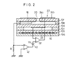
具体的には、上記比較例に係るガスセンサは、図2に示すように、上記基準電極26と内側ポンプ電極24aとの間の両端電圧を基準電圧Vbと比較してその差分を所定のゲインにて増幅して出力する比較増幅器32を設け、該比較増幅器32からの出力電圧(差分電圧)を酸素ポンプ22へのポンプ電圧Vpとして内側ポンプ電極24aと外側ポンプ電極24b間に印加するように配線接続されている。
【0070】
この場合、酸素ポンプ22による酸素の汲み出し量が変化して、ガス導入空間18内における酸素の濃度が変化すると、酸素ポンプ22おける内側ポンプ電極24aと基準電極26間の両端電圧が時間遅れなく変化する(リアルタイムで変化する)ため、上記フィードバック制御での発振現象を有効に抑えることができる。
【0071】
なお、上記フィードバック制御系においては、内側ポンプ電極24aと基準電極26間の両端電圧が上記基準電圧Vbと同じレベルに収束されるように上記ポンプ電圧Vp(出力電圧)がフィードバック制御されることとなる。
【0072】
また、上記比較例に係るガスセンサにおいては、上記構成に加えて、内側ポンプ電極24aとGND間に抵抗Rが接続され、抵抗Rの一端と基準電圧Vbの発生源(電源40)との間に増幅器42(オペアンプ)が挿入接続されて構成されている。具体的には、増幅器42の非反転端子に抵抗Rの上記一端が接続され、増幅器42の反転端子は接地とされ、増幅器42の出力端子は、電源40の負極に接続されて構成されている。
【0073】
つまり、この比較例に係るガスセンサにおいては、酸素ポンプ22による酸素の汲み出しによって内側ポンプ電極24a及び外側ポンプ電極24b間に流れる電流が抵抗Rでの電圧降下によってその電流値に応じた電圧に変換されて、増幅器42の非反転端子に印加されるように配線接続されるものである。
【0074】
通常、酸素ポンプ22による酸素の汲み出しの際に、該酸素ポンプ22に電流(ポンプ電流)が流れることから、酸素ポンプ22のインピーダンスによる電圧降下分がポンプ電圧Vpのレベル調整における誤差として現れることとなる。
しかし、この比較例に係るガスセンサにおいては、酸素ポンプ22に流れるポンプ電流を抵抗Rにて電圧に変換し、該電圧を増幅器42にて所定のゲインで増幅して補正電圧として電源40に重畳させるようにしている。つまり、内側ポンプ電極24aと基準電極26間の電圧は、内側ポンプ電極24aの界面抵抗(インピーダンス)の電圧降下分が重畳されるのみであり、その電圧降下分はかなり下がる。従って、電圧降下分の補正は僅かで済み、その分、精度が向上する。換言すれば、酸素ポンプ22のインピーダンスによる電圧降下分が補正電圧として基準電圧に反映(重畳)することとなり、これによって、ポンプ電圧Vpに対する酸素ポンプ22のインピーダンスによる誤差が有効に吸収され、ポンプ電圧Vpに対するフィードバック制御を精度よく行わせることが可能となる。これは、ガス導入空間18での酸素濃度を高精度に検出することができることにつながる。
【0075】
ところで、上記比較例に係るガスセンサにおいて、酸素ポンプ22における外側ポンプ電極24bと内側ポンプ電極24a間に流れるポンプ電流が大きくなって、(基準電圧+補正電圧)が高くなると、比較増幅器32の出力電圧が高くなり、結果的にポンプ電流が増大するという正帰還となって、発振しやすいという状態となる。実際には、(酸素ポンプ22のインピーダンス×ポンプ電流)に相当する電圧を補正をすることができないことが判明した。
【0076】
図3の特性図はその様子を示したものであり、本実験では、酸素ポンプ22のインピーダンスが、100Ωになるように、酸素ポンプ22の温度が調整されている。このときの内側ポンプ電極24aと基準電極26間のインピーダンスは35Ωであり、補正電圧の理想値は(35Ω×ポンプ電流)であるが、発振により、実際はその1/2の(17.5Ω×ポンプ電流)しか補正できなかった。
【0077】
従って、酸素ポンプ22のインピーダンスが使用過程において増加すると、動作点が限流特性の平坦部から外れてしまう可能性がある。
【0078】
本発明は、上記のような課題を解消するためになされたものであり、簡素な電子部品で、インピーダンスの測定手段、更にそれに基づくヒータ制御、あるいは補正電圧の制御手段等を用いなくても、(酸素ポンプ22のインピーダンス×ポンプ電流)に見合った分、あるいはそれ以上の補正をも可能にし、使用過程において酸素ポンプ22のインピーダンスに増加があっても、限流特性の平坦部で動作ができるものである。
【0079】
発振現象は、単に正帰還によることのみならず、酸素ポンプ22のインピーダンスは図4のように構成され、容量成分を多く含んでいることによる。即ち、酸素ポンプ22のインピーダンスは、抵抗R1と容量C1との並列接続による外側ポンプ電極24bと第2の固体電解質層10fとの界面抵抗Z1と、抵抗R2と容量C2との並列接続による第2の固体電解質層10fにおけるZrO2 粒子間の粒界抵抗Z2と、抵抗Rによる第2の固体電解質層10fにおけるZrO2 粒子抵抗Z3と、抵抗R4と容量C4との並列接続による内側ポンプ電極24aと第2の固体電解質層10fとの界面抵抗Z4とが直列に接続された回路と等価であり、容量成分を多く含んでいる。
【0080】
従って、図5に示すように、例えばポンプ電圧がステップ状に急激に上昇すると、ポンプ電流は、瞬時的に容量C1及び容量C2を通じて抵抗R3及び容量C4を流れて、抵抗R1、抵抗R2及び抵抗R4が無視されるため、大きな電流が流れ、ポンプ電圧が維持されていれば、時間経過と共に、容量C1、容量C2及び容量C4が充電され、結局、抵抗R1+抵抗R2+抵抗R3+抵抗R4で定まる電流値に落ち着く。
【0081】
つまり、基準電圧Vbに重畳される補正電圧は、瞬時的に大きな電圧となり、電流の落ち着きと共に、ある一定値に落ち着く。このポンプ電流のスパイク、ひいては補正電圧のスパイクにより、増幅器42での正帰還電圧が急激に増大し、その結果、発振に至るおそれがある。
【0082】
本発明では、上記ポンプ電流のスパイクを抑えることによって、発振現象の発生を抑制し、補正可能領域(補正可能なダイナミックレンジ)を拡大し、併せて使用過程における酸素ポンプ22のインピーダンスの増大による精度の低下をも改善するものである。
【0083】
次に、第1の実施の形態に係るガスセンサについて図6〜図11を参照しながら説明する。なお、図1と対応するものについては同符号を記す。
【0084】
この第1の実施の形態に係るガスセンサは、上記比較例に係るガスセンサとほぼ同じ構成を有するが、以下の点で異なる。即ち、ポンプ電流検出用の抵抗Riが比較増幅器32の出力端と酸素ポンプ22の外側ポンプ電極24bとの間に挿入接続され、抵抗Riの両端がコンデンサCで短絡され、更に該コンデンサCの一方の電極が差動増幅器44の非反転端子に接続され、他方の電極が差動増幅器44の反転端子に接続されているという点で上記比較例に係るガスセンサと異なる。
【0085】
この実施の形態に係るガスセンサにおいては、上記抵抗RiとコンデンサCとの時定数によって、ポンプ電圧Vpに対するフィードバック制御系に比例積分動作の位相補償回路が挿入接続されたかたちとなり、上記差動増幅器44の出力電圧、即ち補正電圧に発生するスパイク状のノイズは有効に抑制されることとなる。
【0086】
例えば、ポンプ電流が高レベルに立ち上がった場合、その立ち上がり部分の電流によってコンデンサCへの充電が行われるが、本例の場合においては、まず、ポンプ電流のスパイク状の部分によってコンデンサCの充電が行われるため、後段の差動増幅器44に印加される電圧波形は、ほぼ矩形状の信号波形となる。つまり、上記コンデンサCによって、ポンプ電流のスパイク状のノイズが抑圧され、結果として基準電圧に重畳される補正電圧へのスパイク状のノイズも抑圧されることとなる。これは、比較増幅器32によるポンプ電圧Vpに対する調整の高精度化につながり、ガス導入空間18に導入された被測定ガスの酸素濃度を精度よく測定することが可能となる。
【0087】
ここで、本実施の形態に係るガスセンサ(実施例)と上記比較例に係るガスセンサ(比較例)の限流特性に関する一つの実験について説明する。この実験による比較例の限流特性を図7に、実施例の限流特性を図8に示す。この実験においては、酸素ポンプ22のインピーダンスが100Ωになるように加熱して行った。このとき、内側ポンプ電極24aと基準電極26間のインピーダンスは35Ωであり、補正電圧の理想値は(35Ω×ポンプ電流)である。実験を分かり易くするため、差動増幅器44の増幅度を1とした。
【0088】
比較例の場合は、抵抗Rの抵抗値を18Ω以上とすると発振するため、理想値35Ωの1/2の17.5Ωとした。従って、補正量は理想値の1/2になるが、これでも、従来例に係るガスセンサ(図21の特性図参照)と比較すると大きく改善されていることが理解できる。これは、従来例に係るガスセンサでは、酸素ポンプ22のインピーダンスZpの全てを補正する必要があるのに対し、比較例及び実施例では、内側ポンプ電極24aと基準電極26間の電圧に基づくポンプ電圧Vpの制御のため、次式のZ1,Z2,Z3が無視できることとなり、補正すべき電圧降下分が大きく低減された効果によるからである。
【0089】
Zp=Z1+Z2+Z3+Z4
Z1:外側ポンプ電極24bと第2の固体電解質層10fとの界面抵抗
Z2:第2の固体電解質層10fにおけるZrO2 粒子間の界面抵抗
Z3:第2の固体電解質層10fにおけるZrO2 粒子抵抗
Z4:内側ポンプ電極24aと第2の固体電解質層10fとの界面抵抗
コンデンサCを付けた場合(コンデンサCの容量は300μF)、ポンプ電流検出用抵抗Riの抵抗値を35Ωに設定しても、発振は起こらなかったため、35Ωと設定したが、理想値35Ωに対して、約50%増の50Ω近くが発振発生の限界点であることを確認した。
【0090】
図8から明らかなように、コンデンサCを付けた場合は理想の補正ができ、酸素濃度が大きく変化しても、動作点を同じ起電力分の点で、動作させることができる。
【0091】
図9〜図11の特性図は、2.0Lの直列4気筒エンジンの実車にて30,000kmの実車走行をした後の補正の様子を示したものであり、図9は従来例に係るガスセンサの場合を示し、図10は比較例に係るガスセンサ(比較例)の場合を示し、図11は本実施の形態に係るガスセンサ(実施例)の場合を示す。また、図9において、二点鎖線は走行開始段階(初期段階)の特性を示し、実線は30,000km走行した後の特性を示す。図10及び図11において、細い実線は走行開始段階(初期段階)の特性を示し、太い実線は30,000km走行した後の特性を示す。
【0092】
図9〜図11の特性図から、従来例に係るガスセンサでは20%の酸素では全く補正が効かず、5%でようやく平坦部の動作点になるのに対し、実施例では、内側ポンプ電極24aと基準電極26間の電圧に基づくポンプ電圧Vpの制御と、コンデンサCによる発振防止に基づく補正電圧の理想値化の相乗効果により、被測定ガス中の酸素濃度がほぼ大気の20%でも、依然として平坦部の起電力分320mV近傍での動作が可能であり、本実施の形態に係るガスセンサの補正の有用性が理解できる。
【0093】
また、一般に、使用過程における酸素ポンプ22のインピーダンスの増加は、外側ポンプ電極24bの界面抵抗の増加が主原因である。本実施の形態に係るガスセンサによれば、外側ポンプ電極24bを無視した補正であるのに加え、理想値に近い補正ができるため、その相乗効果により、使用過程における酸素ポンプ22のインピーダンスの増大があっても、簡素な構成で、高い精度を維持できる。
【0094】
次に、第1の実施の形態に係るガスセンサのいくつかの変形例について図12〜図14を参照しながら説明する。なお、図6と対応するものについては同符号を記して、その重複説明を省略する。
【0095】
まず、第1の変形例に係るガスセンサは、図12に示すように、図6に示す本実施の形態に係るガスセンサとほぼ同じ構成を有するが、コンデンサCが、差動増幅器44の出力端と接地間に接続されている点で異なる。この第1の変形例に係るガスセンサにおいても、上記実施の形態に係るガスセンサと同様の効果が得られる。この場合、差動増幅器44の出力インピーダンスは一般的に非常に低いため、十分なスパイク除去効果を出すためには、コンデンサCの容量を大きく設定する必要があり、以下に示すように第2の変形例及び第3の変形例の構成を採用することが望ましい。
【0096】
即ち、第2の変形例に係るガスセンサにおいては、図13に示すように、差動増幅器44の出力端と基準電圧Vbの発生源(電源40)との間に抵抗Rを挿入接続し、該抵抗Rの電源40側端と接地間にコンデンサCを接続する。
【0097】
この場合、CRで構成される時定数は、コンデンサCなしで発振したときの発振周期の1/5以上にすると効果的である。上記実験と同じサンプルで確認したところ、発振周期50msecに対して、抵抗Rを10kΩ、コンデンサCを1μFにしたとき、即ち、時定数10msecで発振が停止した。
【0098】
また、第3の変形例に係るガスセンサにおいては、図14に示すように、差動増幅器44の非反転入力端に直列抵抗Rを接続し、その後段における上記差動増幅器44の非反転入力端子と反転入力端子間にコンデンサCを接続する。この場合のCRで構成される時定数は、上記第2の変形例に係るガスセンサの場合とほぼ同じである。
【0099】
次に、第2の実施の形態に係るガスセンサについて図15を参照しながら説明する。
【0100】
この第2の実施の形態に係るガスセンサは、ZrO2 等の酸素イオン伝導性固体電解質を用いたセラミックからなる例えば6枚の固体電解質層10a〜10fが積層されて構成されている点と、これら6枚の固体電解質層10a〜10fが長尺の板状体形状に形成されている点で上記第1の実施の形態に係るガスセンサとほぼ同じであるが、第1及び第2の固体電解質層10d及び10f間に第2のスペース層10eが挟設されると共に、第1及び第2の拡散律速部50及び52が挟設されている点で異なる。
【0101】
そして、第2の固体電解質層10fの下面、第1及び第2の拡散律速部50及び52の側面並びに第1の固体電解質層10dの上面にて被測定ガス中の酸素分圧を調整するための第1室54が区画、形成され、第2の固体電解質層10fの下面、第2の拡散律速部52の側面及び第2のスペース層10eの側面並びに第1の固体電解質層10dの上面にて被測定ガス中の酸化物、例えば窒素酸化物(NOx)を測定するための第2室56が区画、形成される。上記第1室54及び第2室56は、上記第2の拡散律速部52を介して連通されている。
【0102】
また、上記第1の固体電解質層10dの上面のうち、上記第2室56を形づくる上面には、後述する第2の酸素ポンプ58を構成するための一方の電極(上側ポンプ電極60a)が形成され、上記第1の固体電解質層10dの下面のうち、基準ガス導入空間16を形づくる下面であって、かつ上記基準電極26とは別の箇所に第2の酸素ポンプ58を構成するための他方の電極(下側ポンプ電極60b)が形成されている。
【0103】
ここで、上記第1及び第2の拡散律速部50及び52は、第1室54及び第2室56に導入される被測定ガスに対して所定の拡散抵抗を付与するものであり、例えば、被測定ガスを導入することができる多孔質材料又は所定の断面積を有した小孔からなる通路として形成することができる。
【0104】
このガスセンサにおいても、第1室54における内側ポンプ電極24a及び外側ポンプ電極24b間に、上記電位差計28によって検出された電位差Vに基づいて設定されたポンプ電圧Vpが可変電源30により印加されるようになっており、上記酸素ポンプ22は、上記ポンプ電圧Vpの印加によって、第1室54に対して酸素の汲み出し又は汲み入れを行い、これによって、上記第1室54内の酸素分圧が所定値に設定されるようになっている。即ち、このガスセンサは、第1室54、酸素ポンプ22、基準電極26及び基準ガス導入空間16にて構成される酸素濃度制御器62を具備した構成となっており、実質的な窒素酸化物の測定は、第2室56において行われることになる。
【0105】
この第2の実施の形態に係るガスセンサの測定原理を簡単に説明すると、酸素濃度制御器62における酸素ポンプ22によって第1室54内の酸素濃度が、NOxが分解されない程度に、例えば10-7atmになるように、ポンプ電圧Vpが印加される。この10-7atmでNOxが分解されないようにするには、内側ポンプ電極24aにNOx還元性の低い材料、例えばAuとPtの合金を用いることで達成される。
【0106】
第1室54における酸素濃度の検出は、上記第1の実施の形態に係るガスセンサと同様に、酸素ポンプ22における内側ポンプ電極24aと基準電極26間の両端電圧を基準としており、この両端電圧が基準電圧Vbに近づくように、即ち、第1室の酸素濃度がほぼ0となるように上記ポンプ電圧Vpが制御されて酸素ポンプ22に印加されることになる。
【0107】
これによって、第1室54には一酸化窒素(NO)が残る。第1室54に残ったNOは第2の拡散律速部52を通って次の第2室56に流れ込む。この第2室56では、導入されたNOをNとOに分解し、そのうち、酸素Oの濃度を計測して、間接的にNOの濃度を求めるようにしている。NOの分解を起こさせるには、上側ポンプ電極60aに例えばRh,Pt等のNOx還元性を有する材料を用いることにより達成される。
【0108】
この酸素Oの測定は、上側ポンプ電極60aと下側ポンプ電極60bとの間に流れる電流を計測することにより行われる。具体的には、下側ポンプ電極60bと上側ポンプ電極60a間にポンプ電源64を第2室56から酸素O2 を汲み出す方向に接続する。このとき、第2室56に酸素がなければ、上記両電極60a及び60b間での酸素の移動(酸素の汲み出し)は行われないため、該両電極60a及び60b間に電流は流れず、第2室56に酸素があれば、酸素の汲み出し動作によって上記両電極60a及び60b間に電流が流れることになる。従って、ポンプ電源64に直列に電流計66を挿入接続してその電流値を計測することにより、第2室56の酸素濃度を測定することができる。そして、この電流値は、汲み出される酸素の量に比例することから、この電流値からNOの量を定めることが可能となり、これは、同時にNO2 を測定でき得ることと同じである。
【0109】
つまり、この第2の実施の形態に係るガスセンサは、第1室54で被測定ガス中の酸素濃度を低い値で一定にし、第2室56で触媒、又は電気分解で結合酸素を分解し、分解時に発生した酸素を第2の酸素ポンプ58で汲み出し、その汲み出しの際に流れる電流を測定することにより、結合酸素を有するガス成分の濃度を測定するものである。
【0110】
結合酸素を有するガス成分としてNOxを測定するときは、第2室56内の触媒でNOxを分解するのがよい。H2 O,CO2 を測定するときは電気分解によるのがよい。
【0111】
なお、HC等の可燃ガス成分を測定する場合にあっては、以下のように行われる。まず、第1室54の酸素濃度を可燃ガス成分が燃焼しないレベル、例えば10-15 atmとなるようにポンプ電圧を印加し、第2室56では酸素が汲み入れられる方向にポンプ電源を接続して、可燃ガス成分を燃焼させる。このとき、可燃ガス成分が燃焼するのに要した酸素量、即ちポンプ電流を測定することにより、可燃ガス成分の量を求めることができる。
【0112】
そして、この第2の実施の形態に係るガスセンサにおいても、上記第1の実施の形態に係るガスセンサと同様に、酸素濃度制御器62における内側ポンプ電極24aと基準電極26間の電圧を測定し、この測定電圧と基準電圧との差分をとって、その差分電圧によって上記ポンプ電圧Vpを制御するように構成している。
【0113】
具体的には、この第2の実施の形態に係るガスセンサは、図16に示すように、上記基準電極26と内側ポンプ電極24aとの間の両端電圧を基準電圧Vbと比較してその差分を所定のゲインにて増幅して出力する比較増幅器32を有し、該比較増幅器32からの出力電圧(差分電圧)を酸素ポンプ22へのポンプ電圧Vpとして内側ポンプ電極24aと外側ポンプ電極24b間に印加するように配線接続され、ポンプ電流検出用の抵抗Riが比較増幅器32の出力端と酸素ポンプ22の外側ポンプ電極24bとの間に挿入接続され、上記ポンプ電流検出用抵抗Riの両端がコンデンサCで短絡され、更に該コンデンサCの一方の電極が差動増幅器44の非反転端子に、他方の電極が差動増幅器44の反転端子に接続されて構成されている。
【0114】
この第2の実施の形態に係るガスセンサにおいても、比較増幅器32の反転端子に印加される両端電圧(測定電圧)を、酸素ポンプ22における内側ポンプ電極24aと基準ガス導入空間16における基準電極26との間の両端電圧としているため、第1室54内における酸素濃度の変化が時間遅れなく、酸素ポンプ22の内側ポンプ電極24aと基準電極26間の両端電圧の変化として現れ、これにより、上記フィードバック制御での発振現象を有効に抑えることができる。
【0115】
また、上記ポンプ電流検出用の抵抗RiとコンデンサCとの時定数によって、ポンプ電圧Vpに対するフィードバック制御系に比例積分動作の位相補償回路が挿入接続されたかたちとなり、上記差動増幅器44の出力電圧、即ち補正電圧に発生するスパイク状のノイズは有効に抑制されることとなる。これは、比較増幅器32によるポンプ電圧Vpに対する調整の高精度化につながり、第1室54に導入された被測定ガスの酸素濃度を精度よく測定することが可能となる。
【0116】
この第2の実施の形態に係るガスセンサにおいては、上記第1の実施の形態に係るガスセンサの第1の変形例、第2の変形例又は第3の変形例の構成を採用することができる。
【0117】
なお、この発明は上述の実施の形態に限らず、この発明の要旨を逸脱することなく種々の構成を採り得ることはもちろんである。
【0118】
【発明の効果】
以上説明したように、本発明に係るガスセンサによれば、固体電解質からなる基体にて囲まれ、かつ被測定ガスが導入される第1の空間と、前記基体における前記第1の空間の内外に形成された内側電極及び外側電極と、これら両電極にて挟まれた前記基体と、前記両電極間に所定のガス成分を汲み出すための制御電圧を印加するポンプ電源とを有するガスポンプ手段と、固体電解質からなる基体にて囲まれ、かつ基準ガスが導入される第2の空間と、前記基体における前記第2の空間側に形成された基準電極と前記ガスポンプ手段における前記内側電極との間の両端電圧を測定する測定手段と、前記両端電圧に基づいて前記制御電圧のレベルを調整する第1の制御電圧調整手段と、前記ガスポンプ手段による前記ガス成分の汲み出しの際に、該ガスポンプ手段に流れる電流を検出し、その電流値を前記第1の制御電圧調整手段での前記制御電圧のレベル調整に反映させる第2の制御電圧調整手段と、前記第2の制御電圧調整手段に発生するスパイク信号を抑制するスパイク抑制手段とを設けるようにしている。
【0119】
このため、ガスポンプ手段への制御電圧のフィードバック制御系の発振現象を有効に解消することができ、しかも、ガスポンプ手段のインピーダンスによる電圧降下分の誤差を吸収でき、酸素濃度を精度よく検出することができるという効果が達成される。
【0120】
次に、本発明に係るガス濃度制御器によれば、固体電解質からなる基体にて囲まれ、かつ被測定ガスが導入される第1の空間と、前記被測定ガスの前記第1の空間への導入経路に設けられ、前記被測定ガスに対して所定の拡散抵抗を付与するガス拡散律速部と、前記基体における前記第1の空間の内外に形成された内側電極及び外側電極と、これら両電極にて挟まれた前記基体と、前記両電極間に所定のガス成分を汲み出すための制御電圧を印加するポンプ電源とを有するガスポンプ手段と、固体電解質からなる基体にて囲まれ、かつ基準ガスが導入される第2の空間と、前記基体における前記第2の空間側に形成された基準電極と前記ガスポンプ手段における前記内側電極との間の両端電圧を測定する測定手段と、前記両端電圧に基づいて前記制御電圧のレベルを調整する第1の制御電圧調整手段と、前記ガスポンプ手段による前記ガス成分の汲み出しの際に、該ガスポンプ手段に流れる電流を検出し、その電流値を前記第1の制御電圧調整手段での前記制御電圧のレベル調整に反映させる第2の制御電圧調整手段と、前記第2の制御電圧調整手段に発生するスパイク信号を抑制するスパイク抑制手段とを設けるようにしている。
【0121】
このため、ガスポンプ手段への制御電圧のフィードバック制御系の発振現象を有効に解消することができ、しかも、ガスポンプ手段のインピーダンスによる電圧降下分の誤差を吸収でき、酸素濃度を精度よく検出することができるという効果が達成される。
【図面の簡単な説明】
【図1】本発明に係るガスセンサを着想するに至るまでに作製された1つのガスセンサ(以下、単に比較例に係るガスセンサと記す)の概略構成を示す構成図である。
【図2】比較例に係るガスセンサの具体的構成を示す構成図である。
【図3】比較例に係るガスセンサの限流特性を示す特性図である。
【図4】酸素ポンプのインピーダンスを示す等価回路図である。
【図5】補正電圧にスパイク状のノイズが発生する要因を示す波形図である。
【図6】本発明に係るガスセンサを例えば車両の排気ガスや大気中に含まれるNO,NO2 ,SO2 、CO2 、H2 O等の酸化物や、CO,CnHm等の可燃ガスを測定するガスセンサに適用した第1の実施の形態例(以下、単に第1の実施の形態に係るガスセンサと記す)の概略構成を示す構成図である。
【図7】比較例に係るガスセンサの限流特性を示す特性図である。
【図8】実施例に係るガスセンサの限流特性を示す特性図である。
【図9】2.0L直列4気筒エンジンの実車にて30,000kmの実車走行をした後の補正の様子を示すもので、従来例に係るガスセンサの限流特性を示す特性図である。
【図10】2.0L直列4気筒エンジンの実車にて30,000kmの実車走行をした後の補正の様子を示すもので、比較例に係るガスセンサの限流特性を示す特性図である。
【図11】2.0L直列4気筒エンジンの実車にて30,000kmの実車走行をした後の補正の様子を示すもので、実施例に係るガスセンサの限流特性を示す特性図である。
【図12】第1の実施の形態に係るガスセンサの第1の変形例を示す構成図である。
【図13】第1の実施の形態に係るガスセンサの第2の変形例を示す構成図である。
【図14】第1の実施の形態に係るガスセンサの第3の変形例を示す構成図である。
【図15】本発明に係るガスセンサを例えば車両の排気ガスや大気中に含まれるNO,NO2 ,SO2 、CO2 、H2 O等の酸化物や、CO,CnHm等の可燃ガスを測定するガスセンサに適用した第2の実施の形態例(以下、単に第2の実施の形態に係るガスセンサと記す)の概略構成を示す構成図である。
【図16】第2の実施の形態に係るガスセンサの具体的構成を示す構成図である。
【図17】従来例に係る酸素ポンプを用いた限界電流式酸素センサを示す構成図である。
【図18】従来例に係る酸素ポンプを用いた限界電流式酸素センサの限流特性を示す特性図である。
【図19】他の従来例に係るガスセンサを示す構成図である。
【図20】他の従来例に係るガスセンサの限流特性を示す特性図である。
【図21】酸素ポンプを酸素濃度制御器として利用する場合における限流特性を示す特性図である。
【図22】酸素ポンプを利用した従来の全領域型の酸素センサを示す構成図である。
【符号の説明】
16…基準ガス導入空間 18…ガス導入空間
20…拡散律速部 22…酸素ポンプ
24a…内側ポンプ電極 24b…外側ポンプ電極
26…基準電極 32…比較増幅器
44…差動増幅器 Ri…ポンプ電流検出用の抵抗
C…コンデンサ[0001]
BACKGROUND OF THE INVENTION
The present invention is, for example, NO, NO contained in vehicle exhaust gas or air.2, SO2, CO2, H2The present invention relates to a gas sensor and a gas concentration controller for measuring oxides such as O and flammable gases such as CO and CnHm.
[0002]
[Prior art]
Recently, exhaust gases emitted from vehicles such as gasoline cars and diesel engine cars include nitrogen monoxide (NO) and nitrogen dioxide (NO2) And other nitrogen oxides (NOx), carbon monoxide (CO), carbon dioxide (CO2), Water (H2O), hydrocarbon (HC), hydrogen (H2), Oxygen (O2) Etc. are included. In this case, NO accounts for about 80% of the total NOx, and NO and NO2Account for about 95% of the total NOx.
[0003]
Such a three-way catalyst that purifies HC, CO, and NOx contained in the exhaust gas exhibits the maximum purification efficiency near the theoretical air-fuel ratio (A / F = 14.6), and the A / F is set to 16 or more. When controlled, the amount of NOx generated decreases, but the purification efficiency of the catalyst decreases, and as a result, the amount of NOx discharged tends to increase.
[0004]
By the way, recently, in order to effectively use fossil fuels and prevent global warming, CO2There is an increasing market demand for reducing emissions, and there is a growing need to improve fuel efficiency to meet this demand. In response to such demands, for example, research on lean burn engines, research on NOx purification catalysts, and the like have been conducted, and among them, the need for NOx sensors is increasing.
[0005]
Conventionally, there is a NOx analyzer as a device for detecting such NOx. This NOx analyzer measures the characteristics unique to NOx using a chemiluminescence analysis method, but has the disadvantage that the apparatus itself is very large and expensive.
[0006]
In addition, since optical parts are used to detect NOx, complicated maintenance is required. Furthermore, this NOx analyzer measures NOx by sampling, and the detection element itself cannot be directly inserted into the fluid, and a transient phenomenon in which the situation changes frequently, such as automobile exhaust gas. It is not suitable for the analysis.
[0007]
In order to solve these inconveniences, there has been proposed a sensor that measures a desired gas component in exhaust gas by using a substrate made of an oxygen ion conductive solid electrolyte.
[0008]
As a gas sensor according to the proposed example, there is a limiting current type oxygen sensor using an oxygen pump as shown in FIG. This oxygen sensor is configured by laminating three
[0009]
In this oxygen sensor, a constant pump voltage Vp is applied between the
[0010]
Since this sensor applies a constant pump voltage Vp, for example, as shown in FIG. 18, when the oxygen concentration is increased, the electromotive force is reduced by the impedance of the
[0011]
On the other hand, in Japanese Utility Model Publication No. 7-45004, a voltage corresponding to the pump current is created using an operational amplifier, the voltage is fed back to the operational amplifier via a feedback resistor, and connected to a resistor connected in series with the power source. It is shown that when the pump current increases, the voltage at the resistor is superimposed and applied to the pump.
[0012]
This constitutes a circuit as shown in FIG. 19, and the output of the operational amplifier OP is fed back to the input terminal on the atmospheric electrode (
[0013]
By appropriately setting a resistor connected in series with the power supply, a voltage corresponding to (actual pump impedance × pump current) is superimposed on the pump voltage Vp, and the operating point is as shown in FIG. And measuring the oxygen concentration with high accuracy.
[0014]
[Problems to be solved by the invention]
However, in the conventional gas sensor, if the oxygen concentration in the measurement gas increases, the voltage drop increases and becomes much larger than the electromotive force. Therefore, the gas sensor must be operated at an operating point corresponding to a constant electromotive force. Is difficult.
[0015]
When the temperature of the exhaust gas changes greatly as in an automobile, a heater may be provided in the gas sensor and a mechanism for controlling the power supplied to the heater may be provided. The impedance changes slightly. When the pump current increases, a large error occurs in the correction of the voltage drop, and it becomes difficult to accurately measure the high oxygen concentration.
[0016]
In particular, this problem is most serious when the
[0017]
In practice, a voltage corresponding to (pump impedance × pump current) cannot be superimposed on the pump voltage, and there is a problem that the accuracy further decreases.
[0018]
FIG. 21 shows such a situation. In this comparative test, the temperature of the gas sensor is adjusted so that the impedance of the
[0019]
In the conventional method (No. 7-45004), since the impedance of the
[0020]
This is due to oscillation. Above (50Ω × pump current), an oscillation phenomenon occurred in the control, and the control was impossible.
[0021]
In Japanese Utility Model 7-45004, in order to measure the impedance of the oxygen pump, an AC component (500 to 100 kHz) is superimposed on the power source, and the impedance of the oxygen pump is measured with this AC voltage. However, the AC component is positively fed back. Therefore, the oscillation is likely to occur, the output of the operational amplifier OP is positively fed back through the low-pass filter, the AC component is cut, only the DC component (for voltage drop correction) is positively fed back, and the voltage drop is pumped. It is superimposed on the voltage Vp. In the experiment, the frequency for alternating current was 10 kHz, and the cutoff frequency of the low-pass filter was 1 kHz. The heater is not controlled based on the AC signal.
[0022]
According to the experiment, the oscillation phenomenon due to the DC component occurs at a very low frequency of 50 Hz or less, and the problem of the ease of oscillation of the DC component still remains in the low-pass filter that cuts the frequency of several hundred Hz or more.
[0023]
In addition, this method requires an electric circuit of a low-pass filter or a low-pass filter + CR filter, and a method that is simple and has a sufficient effect has been desired.
[0024]
On the other hand, as an all-region type oxygen sensor using an accurate oxygen pump, as shown in FIG. 22, an
[0025]
Also, when measuring gas with bound oxygen (for example, NOx), the oxygen concentration in the gas is lowered to a certain low level by the oxygen pump, then the oxygen concentration is further lowered to decompose NOx and generated during decomposition. A sensor that measures NOx by measuring the oxygen with an oxygen pump is known.
[0026]
This sensor includes an oxygen concentration controller using an oxygen pump, and the oxygen concentration controller controls the oxygen concentration to a constant low level. Therefore, the oxygen concentration controller is required to be more accurate than the oxygen sensor.
[0027]
In the all-region sensor, the pump current is small in the region where the oxygen concentration is low, and the accuracy is less degraded due to the voltage drop due to the pump impedance. On the other hand, in the region where the oxygen concentration is high (for example, several percent), the effect of the voltage drop becomes large and the accuracy decreases, but the oxygen concentration to be measured is several percent (tens of thousands of ppm) and the error is several hundred ppm. However, it is not a big problem.
[0028]
However, for example, when measuring a concentration of several thousand ppm at most, such as a NOx sensor, a change in oxygen concentration of several hundred ppm becomes a large error factor, and this type of gas sensor has an oxygen concentration controller. High control accuracy is required.
[0029]
As shown in FIG. 22, the one that controls the oxygen concentration based on the electromotive force between the
[0030]
That is, in the feedback control, generally, an electromotive force generated between the
[0031]
However, if the gain of the amplifier is set too large, there is a drawback that oscillation occurs in feedback control.
[0032]
This is because the
[0033]
In this case as well, the oxygen partial pressure in the
[0034]
The present invention has been made in consideration of such problems, for example, in the case of using an oxygen pump, it is possible to effectively eliminate the oscillation phenomenon of the feedback control system of the control voltage to the oxygen pump, An object of the present invention is to provide a gas sensor and a gas concentration controller that can absorb an error due to a voltage drop due to an impedance of an oxygen pump and can detect an oxygen concentration with high accuracy.
[0035]
[Means for Solving the Problems]
BookA gas sensor according to an invention includes a first space surrounded by a base made of a solid electrolyte and into which a gas to be measured is introduced, and an inner electrode and an outer electrode formed inside and outside the first space in the base. A gas pump means having a base sandwiched between these electrodes and a pump power supply for applying a control voltage for pumping a predetermined gas component between the electrodes; and a base made of a solid electrolyte. Measuring means for measuring a voltage between both ends of the second space into which the reference gas is introduced, a reference electrode formed on the second space side of the base body, and the inner electrode of the gas pump means; A first control voltage adjusting means for adjusting the level of the control voltage based on the both-ends voltage; and an electric current flowing through the gas pump means when the gas component is pumped out by the gas pump means. And a spike signal generated in the second control voltage adjusting means, and a second control voltage adjusting means for reflecting the current value in the level adjustment of the control voltage in the first control voltage adjusting means. The spike suppression means for suppressing is provided and configured.
[0036]
Thereby, first, the gas to be measured is introduced into the first space, and the both-ends voltage between the inner electrode of the gas pump means and the reference electrode formed on the second space side at that time is measured by the measuring means. . This measurement voltage is supplied to the first control voltage adjusting means. The first control voltage adjusting means adjusts the level of the control voltage to be supplied to the gas pump means based on the measured voltage. The gas pump means pumps a predetermined gas component out of the gas to be measured introduced into the first space by an amount corresponding to the level of the control voltage. By supplying the control voltage adjusted in level to the gas pump means, the concentration of the predetermined gas component in the first space is feedback-controlled to a predetermined level.
[0037]
In this case, the measurement voltage in the measurement means used for adjusting the level of the control voltage is the voltage across the electrode between the inner electrode in the gas pump means and the reference electrode in the second space. Therefore, when the pumping amount of the predetermined gas component by the gas pump means changes and the concentration of the gas component in the first space changes, the voltage across the inner electrode and the reference electrode in the gas pump means changes without time delay. Therefore, the oscillation phenomenon in the feedback control is suppressed.
[0038]
When a predetermined gas component is pumped out by the gas pump means, since a current flows through the gas pump, a voltage drop due to the impedance of the gas pump appears as an error in the level adjustment of the control voltage. In the second control voltage adjusting means, the current flowing in the gas pump means is detected and the current value is reflected in the level adjustment in the first control voltage adjusting means, so that the error is effectively absorbed. The feedback control for the gas pump unit can be performed with high accuracy, and the concentration of the predetermined gas component in the gas to be measured introduced into the first space can be detected with high accuracy.
[0039]
By the way, when the control voltage is changed stepwise by the adjusting operation by the first control voltage adjusting means, for example, a large current flows instantaneously to the gas pump means, and as a result, a spike-like shape is generated in the second control voltage adjusting means. Noise may occur. When the second control voltage adjusting means is configured as a positive feedback type adjusting circuit, there is a possibility that oscillation may occur due to the spike noise.
[0040]
However, in the present invention, since the spike suppression means for suppressing the spike signal generated in the second control voltage adjusting means is provided, the spike-like noise can be effectively suppressed, and the second control Oscillation at the voltage adjusting means can be prevented. This leads to higher accuracy of adjustment with respect to the control voltage in the first control voltage adjusting means, and it is possible to accurately measure the concentration of the predetermined gas component in the gas to be measured introduced into the first space. It becomes.
[0041]
In the above configuration, the first control voltage adjusting means is provided with a comparing means for taking a deviation between the both-end voltage and the comparison voltage, and the level of the control voltage is set based on the deviation obtained by the comparing means. You can adjust itYes.In this case, the control voltage is feedback-controlled so that the voltage between both ends is converged to the comparison voltage.
[0042]
In the above configuration, as the second control voltage adjusting means, when the gas component is pumped out by the gas pump means, a current that flows through the gas pump means is detected and converted into a voltage, and both ends of the resistance An amplifier that amplifies the voltage with a predetermined gain and superimposes it on the comparison voltage may be provided.Yes.As a result, the current generated when the predetermined gas component is pumped out by the gas pump means flows through the resistor, causing a voltage drop in the resistor, and the voltage corresponding to the voltage drop is amplified with a predetermined gain in the amplifier. Thus, it is superimposed on the comparison voltage in the first control voltage adjusting means. That is, the voltage drop due to the impedance of the gas pump means is reflected in the adjustment to the control voltage in the first control voltage adjusting means, and the error based on the impedance of the gas pump means is effectively absorbed and feedback control is performed with high accuracy. It becomes possible to make it.
[0043]
On the other hand, as the spike suppression means, a capacitor connected to both ends of the resistor may be provided.Yes.In this case, a phase compensation circuit for proportional integration operation is inserted and connected to the feedback control system according to the time constant of the resistor and the capacitor, and the spike-like noise generated in the second control voltage adjusting means is effective. It will be suppressed.
[0044]
As the spike suppression means, in addition to the above configuration, a capacitor connected between the resistor and the amplifier may be provided.AndA capacitor connected between the amplifier and the generation source of the comparison voltage may be provided.Yes.
[0045]
Also bookIn the present invention, a gas diffusion rate controlling portion that imparts a predetermined diffusion resistance to the gas to be measured may be provided in the introduction path of the gas to be measured to the first space.Yes.
And in the present invention,A third diffusion space into which the gas to be measured in the first space is introduced and a path for introducing the gas to be measured into the third space, and a predetermined diffusion resistance with respect to the gas to be measured 2nd gas diffusion rate limiting part which givesWhen,Gas component supply means for sending the predetermined gas component into the third space and gas component detection means for detecting the gas component sent by the gas component supply means are provided.Yes.In this case, the amount of the predetermined gas component contained in the gas to be measured can be effectively controlled, and the amount of, for example, oxide or combustible gas in the gas to be measured can be measured with high accuracy.
[0046]
next,BookA gas concentration controller according to the present invention is provided in a first space surrounded by a substrate made of a solid electrolyte and into which a gas to be measured is introduced, and a path for introducing the gas to be measured into the first space. A gas diffusion rate-determining portion that imparts a predetermined diffusion resistance to the gas to be measured, an inner electrode and an outer electrode formed inside and outside the first space in the base, and sandwiched between these electrodes A gas pump means having a base and a pump power source for applying a control voltage for pumping a predetermined gas component between the electrodes, and a first gas surrounded by a base made of a solid electrolyte and introduced with a reference gas. 2, a measuring means for measuring a voltage between the reference electrode formed on the second space side of the base and the inner electrode of the gas pump means, and the control voltage based on the voltage of A first control voltage adjusting means for adjusting a bell; and when the gas component is pumped out by the gas pump means, a current flowing through the gas pump means is detected, and the current value is detected by the first control voltage adjusting means. A second control voltage adjusting means for reflecting the control voltage level adjustment and a spike suppression means for suppressing a spike signal generated in the second control voltage adjusting means are provided.
[0047]
Thereby, first, the gas to be measured is introduced into the first space through the gas diffusion rate controlling portion, and the voltage across the inner electrode of the gas pump means and the reference electrode formed on the second space side at that time is measured. Measured by means. This measurement voltage is supplied to the first control voltage adjusting means. The first control voltage adjusting means adjusts the level of the control voltage to be supplied to the gas pump means based on the measured voltage. The gas pump means pumps a predetermined gas component out of the gas to be measured introduced into the first space by an amount corresponding to the level of the control voltage. By supplying the control voltage adjusted in level to the gas pump means, the concentration of the predetermined gas component in the first space is feedback-controlled to a predetermined level.
[0048]
In this case, the voltage measured by the measuring means used for adjusting the level of the control voltage is the voltage across the inner electrode of the gas pump means and the reference electrode in the second space. Therefore, when the pumping amount of the predetermined gas component by the gas pump means changes and the concentration of the gas component in the first space changes, the voltage across the inner electrode and the reference electrode in the gas pump means changes without time delay. Therefore, the oscillation phenomenon in the feedback control is suppressed.
[0049]
When a predetermined gas component is pumped out by the gas pump means, since a current flows through the gas pump, a voltage drop due to the impedance of the gas pump appears as an error in the level adjustment of the control voltage. In the second control voltage adjusting means, the current flowing in the gas pump means is detected and the current value is reflected in the level adjustment in the first control voltage adjusting means, so that the error is effectively absorbed. The feedback control for the gas pump unit can be performed with high accuracy, and the concentration of the predetermined gas component in the gas to be measured introduced into the first space can be detected with high accuracy.
[0050]
By the way, when the control voltage is changed stepwise by the adjusting operation by the first control voltage adjusting means, for example, a large current flows instantaneously to the gas pump means, and as a result, a spike-like shape is generated in the second control voltage adjusting means. Noise may occur. When the second control voltage adjusting means is configured as a positive feedback type adjusting circuit, there is a possibility that oscillation may occur due to the spike noise.
[0051]
However, in the present invention, since the spike suppression means for suppressing the spike signal generated in the second control voltage adjusting means is provided, the spike-like noise can be effectively suppressed, and the second control Oscillation at the voltage adjusting means can be prevented. This leads to higher accuracy of adjustment with respect to the control voltage in the first control voltage adjusting means, and it is possible to accurately measure the concentration of the predetermined gas component in the gas to be measured introduced into the first space. It becomes.
[0052]
In the above configuration, the first control voltage adjusting means is provided with a comparing means for taking a deviation between the both-end voltage and the comparison voltage, and the level of the control voltage is set based on the deviation obtained by the comparing means. You can adjust itYes.In this case, the control voltage is feedback-controlled so that the voltage between both ends is converged to the comparison voltage.
[0053]
In the above configuration, as the second control voltage adjusting means, when the gas component is pumped out by the gas pump means, a current that flows through the gas pump means is detected and converted into a voltage, and both ends of the resistance An amplifier that amplifies the voltage with a predetermined gain and superimposes it on the comparison voltage may be provided.Yes.As a result, the current generated when the predetermined gas component is pumped out by the gas pump means flows through the resistor, causing a voltage drop in the resistor, and the voltage corresponding to the voltage drop is amplified with a predetermined gain in the amplifier. Thus, it is superimposed on the comparison voltage in the first control voltage adjusting means. That is, the voltage drop due to the impedance of the gas pump means is reflected in the adjustment to the control voltage in the first control voltage adjusting means, and the error based on the impedance of the gas pump means is effectively absorbed and feedback control is performed with high accuracy. It becomes possible to make it.
[0054]
On the other hand, as the spike suppression means, a capacitor connected to both ends of the resistor may be provided.Yes.In this case, a phase compensation circuit for proportional integration operation is inserted and connected to the feedback control system according to the time constant of the resistor and the capacitor, and the spike-like noise generated in the second control voltage adjusting means is effective. It will be suppressed.
[0055]
As the spike suppression means, in addition to the above configuration, a capacitor connected between the resistor and the amplifier may be provided.AndA capacitor connected between the amplifier and the generation source of the comparison voltage may be provided.Yes.
And in this invention, it is provided in the 3rd space into which the to-be-measured gas in the said 1st space is introduce | transduced, the introduction path | route to the said 3rd space of the to-be-measured gas, and the to-be-measured gas A second gas diffusion rate-determining unit that provides a predetermined diffusion resistance, a gas component supply means that sends the predetermined gas component into the third space, and the gas component that is sent by the gas component supply means. Gas component detecting means for detecting is provided. In this case, the amount of the predetermined gas component contained in the gas to be measured can be effectively controlled, and the amount of, for example, oxide or combustible gas in the gas to be measured can be measured with high accuracy.
[0056]
DETAILED DESCRIPTION OF THE INVENTION
Hereinafter, the gas sensor according to the present invention is, for example, NO, NO contained in vehicle exhaust gas or the atmosphere.2, SO2, CO2, H2Two embodiments applied to a gas sensor for measuring an oxide such as O and a combustible gas such as CO and CnHm (hereinafter simply referred to as the gas sensor according to the first embodiment and the gas sensor according to the second embodiment) Will be described with reference to FIGS.
[0057]
First, before describing the gas sensor according to the present embodiment, a configuration of one gas sensor (hereinafter referred to as a gas sensor according to a comparative example for convenience) produced until the gas sensor according to the present invention is conceived. explain.
[0058]
As shown in FIG. 1, the gas sensor according to this comparative example has a ZrO2For example, six
[0059]
Specifically, the
[0060]
Between the
[0061]
Between the first and second
[0062]
Of the lower surface of the second
[0063]
A
[0064]
In this case, oxygen concentration cell power is generated based on the difference between the oxygen partial pressure of the atmosphere introduced into the reference
[0065]
V = RT / 4F · ln (P1 (O2) / P0 (O2))
R: Gas constant
T: Absolute temperature
F: Faraday number
P1 (O2): Oxygen partial pressure in the gas introduction space
P0 (O2): Oxygen partial pressure of the reference gas
Accordingly, the partial pressure of oxygen in the
[0066]
Further, the
[0067]
In general, a pump voltage Vp set based on the potential difference V detected by the
[0068]
The gas sensor according to the comparative example measures the voltage between the
[0069]
Specifically, as shown in FIG. 2, the gas sensor according to the comparative example compares the voltage across the
[0070]
In this case, when the amount of oxygen pumped out by the
[0071]
In the feedback control system, the pump voltage Vp (output voltage) is feedback controlled so that the voltage between both ends of the
[0072]
In addition, in the gas sensor according to the comparative example, in addition to the above configuration, a resistor R is connected between the
[0073]
That is, in the gas sensor according to this comparative example, the current flowing between the
[0074]
Normally, when oxygen is pumped out by the
However, in the gas sensor according to this comparative example, the pump current flowing through the
[0075]
By the way, in the gas sensor according to the comparative example, when the pump current flowing between the
[0076]
The characteristic diagram of FIG. 3 shows this state. In this experiment, the temperature of the
[0077]
Therefore, if the impedance of the
[0078]
The present invention has been made to solve the above-described problems, and is a simple electronic component, without using impedance measurement means, heater control based on it, or correction voltage control means, etc. Correction corresponding to (impedance of oxygen pump 22 × pump current) or more can be made, and even if there is an increase in impedance of
[0079]
The oscillation phenomenon is not only due to positive feedback, but also because the impedance of the
[0080]
Therefore, as shown in FIG. 5, for example, when the pump voltage suddenly increases stepwise, the pump current instantaneously flows through the resistor R3 and the capacitor C4 through the capacitor C1 and the capacitor C2, and thus the resistor R1, the resistor R2, and the resistor Since R4 is ignored, if a large current flows and the pump voltage is maintained, the capacitor C1, the capacitor C2, and the capacitor C4 are charged with time, and eventually, the current determined by the resistor R1 + the resistor R2 + the resistor R3 + the resistor R4 Settling in value.
[0081]
That is, the correction voltage superimposed on the reference voltage Vb instantaneously becomes a large voltage and settles to a certain value as the current settles. The pump current spike, and hence the correction voltage spike, causes the positive feedback voltage at the
[0082]
In the present invention, the occurrence of an oscillation phenomenon is suppressed by suppressing the spike of the pump current, the correctable region (correctable dynamic range) is expanded, and the accuracy due to the increase in impedance of the
[0083]
Next, the gas sensor according to the first embodiment will be described with reference to FIGS. Note that components corresponding to those in FIG.
[0084]
The gas sensor according to the first embodiment has substantially the same configuration as the gas sensor according to the comparative example, but differs in the following points. That is, a pump current detection resistor Ri is inserted and connected between the output terminal of the
[0085]
In the gas sensor according to this embodiment, a phase compensation circuit for proportional integration operation is inserted and connected to the feedback control system for the pump voltage Vp according to the time constant of the resistor Ri and the capacitor C. The spike noise generated in the output voltage, i.e., the correction voltage is effectively suppressed.
[0086]
For example, when the pump current rises to a high level, the capacitor C is charged by the current at the rising portion. In this example, the capacitor C is first charged by the spiked portion of the pump current. Therefore, the voltage waveform applied to the
[0087]
Here, one experiment regarding the current limiting characteristics of the gas sensor according to the present embodiment (example) and the gas sensor according to the comparative example (comparative example) will be described. FIG. 7 shows the current limiting characteristics of the comparative example in this experiment, and FIG. 8 shows the current limiting characteristics of the example. In this experiment, the
[0088]
In the case of the comparative example, since the oscillation occurs when the resistance value of the resistor R is 18Ω or more, it is set to 17.5Ω which is 1/2 of the ideal value of 35Ω. Therefore, although the correction amount is ½ of the ideal value, it can be understood that this is greatly improved as compared with the conventional gas sensor (see the characteristic diagram of FIG. 21). This is because, in the gas sensor according to the conventional example, it is necessary to correct all of the impedance Zp of the
[0089]
Zp = Z1 + Z2 + Z3 + Z4
Z1: Interface resistance between the
Z2: ZrO in the second
Z3: ZrO in the second
Z4: Interface resistance between the
When capacitor C is attached (capacitor C has a capacity of 300 μF), even if the resistance value of the pump current detection resistor Ri is set to 35Ω, oscillation does not occur, so it is set to 35Ω. It was confirmed that the limit of oscillation generation was about 50Ω, an increase of about 50%.
[0090]
As is apparent from FIG. 8, when the capacitor C is attached, ideal correction can be performed, and even if the oxygen concentration changes greatly, the operating point can be operated at the same electromotive force.
[0091]
The characteristic diagrams of FIGS. 9 to 11 show the state of correction after running a real vehicle of 30,000 km in a real vehicle of a 2.0 L in-line four-cylinder engine. FIG. 9 is a gas sensor according to a conventional example. FIG. 10 shows the case of a gas sensor (comparative example) according to a comparative example, and FIG. 11 shows the case of a gas sensor (example) according to the present embodiment. In FIG. 9, the two-dot chain line indicates the characteristics at the travel start stage (initial stage), and the solid line indicates the characteristics after traveling 30,000 km. 10 and 11, the thin solid line indicates the characteristics at the travel start stage (initial stage), and the thick solid line indicates the characteristics after traveling 30,000 km.
[0092]
From the characteristic diagrams of FIGS. 9 to 11, the gas sensor according to the conventional example is not corrected at all with 20% oxygen and finally becomes the operating point of the flat portion at 5%, whereas in the embodiment, the
[0093]
In general, the increase in impedance of the
[0094]
Next, some modifications of the gas sensor according to the first embodiment will be described with reference to FIGS. Note that components corresponding to those in FIG. 6 are denoted by the same reference numerals, and redundant description thereof is omitted.
[0095]
First, as shown in FIG. 12, the gas sensor according to the first modification has almost the same configuration as the gas sensor according to the present embodiment shown in FIG. 6, but the capacitor C is connected to the output terminal of the
[0096]
That is, in the gas sensor according to the second modification, as shown in FIG. 13, a resistor R is inserted and connected between the output terminal of the
[0097]
In this case, it is effective to set the time constant constituted by CR to 1/5 or more of the oscillation period when oscillation is performed without the capacitor C. When confirmed with the same sample as the above experiment, the oscillation stopped when the resistance R was 10 kΩ and the capacitor C was 1 μF with respect to the oscillation period of 50 msec, that is, with a time constant of 10 msec.
[0098]
In the gas sensor according to the third modification, as shown in FIG. 14, a series resistance R is connected to the non-inverting input terminal of the
[0099]
Next, a gas sensor according to a second embodiment will be described with reference to FIG.
[0100]
The gas sensor according to the second embodiment is made of ZrO.2For example, six
[0101]
In order to adjust the partial pressure of oxygen in the gas to be measured on the lower surface of the second
[0102]
Also, one of the upper surfaces of the first
[0103]
Here, the first and second diffusion rate-limiting
[0104]
Also in this gas sensor, the pump voltage Vp set based on the potential difference V detected by the
[0105]
The measurement principle of the gas sensor according to the second embodiment will be briefly described. The oxygen concentration in the
[0106]
The detection of the oxygen concentration in the
[0107]
As a result, nitrogen monoxide (NO) remains in the
[0108]
This measurement of oxygen O is performed by measuring the current flowing between the
[0109]
That is, in the gas sensor according to the second embodiment, the oxygen concentration in the gas to be measured is made constant at a low value in the
[0110]
When measuring NOx as a gas component having bound oxygen, it is preferable to decompose NOx with the catalyst in the
[0111]
In addition, when measuring combustible gas components, such as HC, it carries out as follows. First, the oxygen concentration in the
[0112]
In the gas sensor according to the second embodiment, as in the gas sensor according to the first embodiment, the voltage between the
[0113]
Specifically, as shown in FIG. 16, the gas sensor according to the second embodiment compares the voltage across the
[0114]
Also in the gas sensor according to the second embodiment, the both-end voltage (measurement voltage) applied to the inverting terminal of the
[0115]
Further, a phase compensation circuit for proportional integration operation is inserted and connected to the feedback control system for the pump voltage Vp according to the time constant of the pump current detection resistor Ri and capacitor C, and the output voltage of the
[0116]
In the gas sensor according to the second embodiment, the configuration of the first modification, the second modification, or the third modification of the gas sensor according to the first embodiment can be employed.
[0117]
Note that the present invention is not limited to the above-described embodiment, and various configurations can be adopted without departing from the gist of the present invention.
[0118]
【The invention's effect】
As described above, according to the gas sensor of the present invention, the first space surrounded by the solid electrolyte substrate and into which the gas to be measured is introduced, and the inside and outside of the first space in the substrate. A gas pump means having an inner electrode and an outer electrode formed, the base body sandwiched between both electrodes, and a pump power source for applying a control voltage for pumping a predetermined gas component between the electrodes; A second space surrounded by a solid electrolyte substrate and into which a reference gas is introduced; a reference electrode formed on the second space side of the substrate; and the inner electrode of the gas pump means. A measuring means for measuring a voltage at both ends, a first control voltage adjusting means for adjusting the level of the control voltage based on the voltage at both ends, and when the gas component is pumped out by the gas pump means A second control voltage adjusting means for detecting a current flowing through the gas pump means and reflecting the current value in the level adjustment of the control voltage in the first control voltage adjusting means; and the second control voltage adjusting means. And spike suppression means for suppressing the spike signal generated at the same time.
[0119]
For this reason, it is possible to effectively eliminate the oscillation phenomenon of the feedback control system of the control voltage to the gas pump means, and to absorb the error due to the voltage drop due to the impedance of the gas pump means and to detect the oxygen concentration with high accuracy. The effect of being able to be achieved is achieved.
[0120]
Next, according to the gas concentration controller of the present invention, the first space surrounded by the base made of the solid electrolyte and into which the measurement gas is introduced, and the first space of the measurement gas are introduced. A gas diffusion rate-determining portion that is provided in the introduction path and gives a predetermined diffusion resistance to the gas to be measured; an inner electrode and an outer electrode formed inside and outside the first space in the base; A gas pump means having a base sandwiched between electrodes and a pump power source for applying a control voltage for pumping a predetermined gas component between the electrodes; a base made of a solid electrolyte; and a reference A second space into which gas is introduced; a measuring means for measuring a voltage between both ends of the base electrode formed on the second space side of the substrate and the inner electrode of the gas pump means; On the basis of the A first control voltage adjusting means for adjusting the level of the control voltage; and when the gas component is pumped out by the gas pump means, a current flowing through the gas pump means is detected, and the current value is detected as the first control voltage. Second control voltage adjusting means for reflecting the control voltage level adjustment in the adjusting means and spike suppression means for suppressing spike signals generated in the second control voltage adjusting means are provided.
[0121]
For this reason, it is possible to effectively eliminate the oscillation phenomenon of the feedback control system of the control voltage to the gas pump means, and to absorb the error due to the voltage drop due to the impedance of the gas pump means and to detect the oxygen concentration with high accuracy. The effect of being able to be achieved is achieved.
[Brief description of the drawings]
FIG. 1 is a configuration diagram showing a schematic configuration of one gas sensor (hereinafter simply referred to as a gas sensor according to a comparative example) manufactured up to the idea of a gas sensor according to the present invention.
FIG. 2 is a configuration diagram showing a specific configuration of a gas sensor according to a comparative example.
FIG. 3 is a characteristic diagram showing current limiting characteristics of a gas sensor according to a comparative example.
FIG. 4 is an equivalent circuit diagram showing the impedance of the oxygen pump.
FIG. 5 is a waveform diagram showing factors that cause spike noise in the correction voltage;
FIG. 6 shows a gas sensor according to the present invention, for example, NO, NO contained in vehicle exhaust gas or air.2, SO2, CO2, H2Configuration showing a schematic configuration of a first embodiment (hereinafter simply referred to as a gas sensor according to the first embodiment) applied to a gas sensor for measuring an oxide such as O or a combustible gas such as CO or CnHm. FIG.
FIG. 7 is a characteristic diagram showing current limiting characteristics of a gas sensor according to a comparative example.
FIG. 8 is a characteristic diagram showing current limiting characteristics of the gas sensor according to the example.
FIG. 9 is a characteristic diagram showing a current limiting characteristic of a gas sensor according to a conventional example, showing a state of correction after running a real vehicle of 30,000 km in a real vehicle of a 2.0 L in-line four-cylinder engine.
FIG. 10 is a characteristic diagram showing a current limiting characteristic of a gas sensor according to a comparative example, showing a state of correction after running a real vehicle of 30,000 km in a real vehicle of a 2.0 L in-line four-cylinder engine.
FIG. 11 is a characteristic diagram showing a current limiting characteristic of a gas sensor according to an example, showing a state of correction after running a real vehicle of 30,000 km in a real vehicle of a 2.0 L in-line four-cylinder engine.
FIG. 12 is a configuration diagram showing a first modification of the gas sensor according to the first embodiment.
FIG. 13 is a configuration diagram showing a second modification of the gas sensor according to the first embodiment.
FIG. 14 is a configuration diagram showing a third modification of the gas sensor according to the first embodiment.
FIG. 15 shows a gas sensor according to the present invention, for example, NO, NO contained in vehicle exhaust gas or air.2, SO2, CO2, H2Configuration showing a schematic configuration of a second embodiment (hereinafter simply referred to as a gas sensor according to the second embodiment) applied to a gas sensor for measuring an oxide such as O or a combustible gas such as CO or CnHm. FIG.
FIG. 16 is a configuration diagram showing a specific configuration of a gas sensor according to a second embodiment.
FIG. 17 is a configuration diagram showing a limiting current type oxygen sensor using an oxygen pump according to a conventional example.
FIG. 18 is a characteristic diagram showing a current limiting characteristic of a limiting current type oxygen sensor using an oxygen pump according to a conventional example.
FIG. 19 is a configuration diagram showing a gas sensor according to another conventional example.
FIG. 20 is a characteristic diagram showing current limiting characteristics of a gas sensor according to another conventional example.
FIG. 21 is a characteristic diagram showing a current limiting characteristic when an oxygen pump is used as an oxygen concentration controller.
FIG. 22 is a configuration diagram showing a conventional all-region type oxygen sensor using an oxygen pump.
[Explanation of symbols]
16 ... Reference
20 ... Diffusion-limiting
24a ...
26 ...
44 ... Differential amplifier Ri ... Resistance for detecting pump current
C: Capacitor
Claims (13)
前記基体における前記第1の空間の内外に形成された内側電極及び外側電極と、これら両電極にて挟まれた前記基体と、前記両電極間に所定のガス成分を汲み出すための制御電圧を印加するポンプ電源とを有するガスポンプ手段と、
固体電解質からなる基体にて囲まれ、かつ基準ガスが導入される第2の空間と、
前記基体における前記第2の空間側に形成された基準電極と前記ガスポンプ手段における前記内側電極との間の両端電圧を測定する測定手段と、
前記両端電圧に基づいて前記制御電圧のレベルを調整する第1の制御電圧調整手段と、
前記ガスポンプ手段による前記ガス成分の汲み出しの際に、該ガスポンプ手段に流れる電流を検出し、その電流値を前記第1の制御電圧調整手段での前記制御電圧のレベル調整に反映させる第2の制御電圧調整手段と、
前記第2の制御電圧調整手段に発生するスパイク信号を抑制するスパイク抑制手段とを有し、
さらに、前記第1の空間内の被測定ガスが導入される第3の空間と、
前記被測定ガスの前記第3の空間への導入経路に設けられ、前記被測定ガスに対して所定の拡散抵抗を付与する第2のガス拡散律速部と、
前記第3の空間内に前記所定のガス成分を送り込むガス成分供給手段と、
前記ガス成分供給手段により送り込まれる前記ガス成分を検出するガス成分検出手段とを有することを特徴とするガスセンサ。A first space surrounded by a solid electrolyte substrate and into which a gas to be measured is introduced;
An inner electrode and an outer electrode formed inside and outside the first space in the base, the base sandwiched between the two electrodes, and a control voltage for pumping a predetermined gas component between the two electrodes A gas pump means having a pump power supply to apply;
A second space surrounded by a solid electrolyte substrate and into which a reference gas is introduced;
Measuring means for measuring a voltage between both ends of a reference electrode formed on the second space side of the base body and the inner electrode of the gas pump means;
First control voltage adjusting means for adjusting the level of the control voltage based on the both-end voltage;
When the gas component is pumped out by the gas pump means, a second control for detecting a current flowing through the gas pump means and reflecting the current value in the level adjustment of the control voltage in the first control voltage adjusting means. Voltage adjusting means;
Possess a suppressing spike suppression means a spike signal generated in said second control voltage adjusting means,
Furthermore, a third space into which the gas to be measured in the first space is introduced,
A second gas diffusion rate limiting unit provided in a path for introducing the gas to be measured into the third space and imparting a predetermined diffusion resistance to the gas to be measured;
Gas component supply means for feeding the predetermined gas component into the third space;
The gas sensor characterized by have a gas component detection means for detecting the gas component fed by said gas component supply means.
前記第1の制御電圧調整手段は、前記両端電圧と比較電圧との偏差をとる比較手段を有し、該比較手段にて得られた偏差に基づいて前記制御電圧のレベルを調整することを特徴とするガスセンサ。The gas sensor according to claim 1, wherein
The first control voltage adjusting means has a comparing means for taking a deviation between the both-end voltage and a comparison voltage, and adjusts the level of the control voltage based on the deviation obtained by the comparing means. Gas sensor.
前記第2の制御電圧調整手段は、ガスポンプ手段による前記ガス成分の汲み出しの際に、該ガスポンプ手段に流れる電流を検出して電圧に変換する抵抗と、該抵抗の両端電圧を所定のゲインにて増幅して前記比較電圧に重畳させる増幅器を有することを特徴とするガスセンサ。The gas sensor according to claim 2, wherein
The second control voltage adjusting unit detects a current flowing through the gas pump unit when the gas component is pumped out by the gas pump unit, and converts the voltage across the resistor into a voltage and a voltage across the resistor with a predetermined gain. A gas sensor comprising an amplifier that amplifies and superimposes the amplified voltage on the comparison voltage.
前記スパイク抑制手段は、前記抵抗の両端に接続される容量を有することを特徴とするガスセンサ。The gas sensor according to claim 3, wherein
The gas sensor according to claim 1, wherein the spike suppression means has a capacity connected to both ends of the resistor.
前記スパイク抑制手段は、前記抵抗と前記増幅器間に接続される容量を有することを特徴とするガスセンサ。The gas sensor according to claim 3 or 4,
The gas sensor according to claim 1, wherein the spike suppression means has a capacitance connected between the resistor and the amplifier.
前記スパイク抑制手段は、前記増幅器と前記比較電圧の発生源との間に接続される容量を有することを特徴とするガスセンサ。The gas sensor according to claim 3, wherein
The spike suppression means has a capacity connected between the amplifier and the generation source of the comparison voltage.
前記被測定ガスの前記第1の空間への導入経路に設けられ、前記被測定ガスに対して所定の拡散抵抗を付与するガス拡散律速部と、
前記基体における前記第1の空間の内外に形成された内側電極及び外側電極と、これら両電極にて挟まれた前記基体と、前記両電極間に所定のガス成分を汲み出すための制御電圧を印加するポンプ電源とを有するガスポンプ手段と、
固体電解質からなる基体にて囲まれ、かつ基準ガスが導入される第2の空間と、
前記基体における前記第2の空間側に形成された基準電極と前記ガスポンプ手段における前記内側電極との間の両端電圧を測定する測定手段と、
前記両端電圧に基づいて前記制御電圧のレベルを調整する第1の制御電圧調整手段と、
前記ガスポンプ手段による前記ガス成分の汲み出しの際に、該ガスポンプ手段に流れる電流を検出し、その電流値を前記第1の制御電圧調整手段での前記制御電圧のレベル調整に反映させる第2の制御電圧調整手段と、
前記第2の制御電圧調整手段に発生するスパイク信号を抑制するスパイク抑制手段とを有し、
さらに、前記第1の空間内の被測定ガスが導入される第3の空間と、
前記被測定ガスの前記第3の空間への導入経路に設けられ、前記被測定ガスに対して所定の拡散抵抗を付与する第2のガス拡散律速部と、
前記第3の空間内に前記所定のガス成分を送り込むガス成分供給手段と、
前記ガス成分供給手段により送り込まれる前記ガス成分を検出するガス成分検出手段とを有することを特徴とするガス濃度制御器。A first space surrounded by a solid electrolyte substrate and into which a gas to be measured is introduced;
A gas diffusion rate limiting unit that is provided in the introduction path of the gas to be measured into the first space and that gives a predetermined diffusion resistance to the gas to be measured;
An inner electrode and an outer electrode formed inside and outside the first space in the base, the base sandwiched between the two electrodes, and a control voltage for pumping a predetermined gas component between the two electrodes A gas pump means having a pump power supply to apply;
A second space surrounded by a solid electrolyte substrate and into which a reference gas is introduced;
Measuring means for measuring a voltage between both ends of a reference electrode formed on the second space side of the base body and the inner electrode of the gas pump means;
First control voltage adjusting means for adjusting the level of the control voltage based on the both-end voltage;
When the gas component is pumped out by the gas pump means, a second control for detecting a current flowing through the gas pump means and reflecting the current value in the level adjustment of the control voltage in the first control voltage adjusting means. Voltage adjusting means;
Possess a suppressing spike suppression means a spike signal generated in said second control voltage adjusting means,
Furthermore, a third space into which the gas to be measured in the first space is introduced,
A second gas diffusion rate limiting unit provided in a path for introducing the gas to be measured into the third space and imparting a predetermined diffusion resistance to the gas to be measured;
Gas component supply means for feeding the predetermined gas component into the third space;
Gas concentration controller, characterized by have a gas component detection means for detecting the gas component fed by said gas component supply means.
前記第1の制御電圧調整手段は、前記両端電圧と比較電圧との偏差をとる比較手段を有し、該比較手段にて得られた偏差に基づいて前記制御電圧のレベルを調整することを特徴とするガス濃度制御器。The gas concentration controller according to claim 8 , wherein
The first control voltage adjusting means has a comparing means for taking a deviation between the both-end voltage and a comparison voltage, and adjusts the level of the control voltage based on the deviation obtained by the comparing means. Gas concentration controller.
前記第2の制御電圧調整手段は、ガスポンプ手段による前記ガス成分の汲み出しの際に、該ガスポンプ手段に流れる電流を検出して電圧に変換する抵抗と、該抵抗の両端電圧を所定のゲインにて増幅して前記比較電圧に重畳させる増幅器を有することを特徴とするガス濃度制御器。The gas concentration controller according to claim 9 , wherein
The second control voltage adjusting unit detects a current flowing through the gas pump unit when the gas component is pumped out by the gas pump unit, and converts the voltage across the resistor into a voltage and a voltage across the resistor with a predetermined gain. A gas concentration controller comprising an amplifier that amplifies and superimposes on the comparison voltage.
前記スパイク抑制手段は、前記抵抗の両端に接続される容量を有することを特徴とするガス濃度制御器。The gas concentration controller according to claim 10 , wherein
The gas concentration controller, wherein the spike suppression means has a capacity connected to both ends of the resistor.
前記スパイク抑制手段は、前記抵抗と前記増幅器間に接続される容量を有することを特徴とするガス濃度制御器。The gas concentration controller according to claim 10 or 11 ,
The gas concentration controller, wherein the spike suppression means has a capacity connected between the resistor and the amplifier.
前記スパイク抑制手段は、前記増幅器と前記比較電圧の発生源との間に接続される容量を有することを特徴とするガス濃度制御器。The gas concentration controller according to claim 10 , wherein
The gas concentration controller, wherein the spike suppression means has a capacity connected between the amplifier and the generation source of the comparison voltage.
Priority Applications (4)
| Application Number | Priority Date | Filing Date | Title |
|---|---|---|---|
| JP17024696A JP3692183B2 (en) | 1996-06-28 | 1996-06-28 | Gas sensor and gas concentration controller |
| US08/882,071 US6093294A (en) | 1996-06-28 | 1997-06-25 | Gas sensor and gas concentration controller |
| DE69736091T DE69736091T2 (en) | 1996-06-28 | 1997-06-27 | Gas sensor and gas concentration monitoring device |
| EP97304664A EP0816835B1 (en) | 1996-06-28 | 1997-06-27 | Gas sensor and gas concentration controller |
Applications Claiming Priority (1)
| Application Number | Priority Date | Filing Date | Title |
|---|---|---|---|
| JP17024696A JP3692183B2 (en) | 1996-06-28 | 1996-06-28 | Gas sensor and gas concentration controller |
Publications (2)
| Publication Number | Publication Date |
|---|---|
| JPH1019841A JPH1019841A (en) | 1998-01-23 |
| JP3692183B2 true JP3692183B2 (en) | 2005-09-07 |
Family
ID=15901389
Family Applications (1)
| Application Number | Title | Priority Date | Filing Date |
|---|---|---|---|
| JP17024696A Expired - Fee Related JP3692183B2 (en) | 1996-06-28 | 1996-06-28 | Gas sensor and gas concentration controller |
Country Status (4)
| Country | Link |
|---|---|
| US (1) | US6093294A (en) |
| EP (1) | EP0816835B1 (en) |
| JP (1) | JP3692183B2 (en) |
| DE (1) | DE69736091T2 (en) |
Families Citing this family (11)
| Publication number | Priority date | Publication date | Assignee | Title |
|---|---|---|---|---|
| JP4005273B2 (en) * | 1998-09-16 | 2007-11-07 | 株式会社デンソー | Gas concentration detector |
| US6389803B1 (en) * | 2000-08-02 | 2002-05-21 | Ford Global Technologies, Inc. | Emission control for improved vehicle performance |
| US7114325B2 (en) * | 2004-07-23 | 2006-10-03 | Ford Global Technologies, Llc | Control system with a sensor |
| US7611612B2 (en) * | 2005-07-14 | 2009-11-03 | Ceramatec, Inc. | Multilayer ceramic NOx gas sensor device |
| JP4704957B2 (en) * | 2006-05-26 | 2011-06-22 | 日本特殊陶業株式会社 | Abnormality diagnosis method for gas sensor system and gas sensor system |
| WO2008103311A2 (en) * | 2007-02-16 | 2008-08-28 | Ceramatec, Inc. | Nox sensor with improved selectivity and sensitivity |
| WO2010003826A1 (en) * | 2008-07-10 | 2010-01-14 | Robert Bosch Gmbh | Sensor element and method for determining gas components in gas mixtures and use thereof |
| DE102009037706A1 (en) | 2009-08-17 | 2011-02-24 | Opsolution Nanophotonics Gmbh | Method and device for determining the concentration of NO 2 in gas mixtures |
| DE102009050224B4 (en) * | 2009-10-22 | 2016-03-31 | Continental Automotive Gmbh | Device and method for controlling an exhaust gas sensor |
| DK2647988T3 (en) * | 2012-04-05 | 2015-08-10 | Werner Reiter | METHOD AND DEVICE FOR MEASURING OR oxygen partial pressure of oxygen IN A measurement gas |
| US9164080B2 (en) | 2012-06-11 | 2015-10-20 | Ohio State Innovation Foundation | System and method for sensing NO |
Family Cites Families (13)
| Publication number | Priority date | Publication date | Assignee | Title |
|---|---|---|---|---|
| JPS57192855A (en) * | 1981-05-25 | 1982-11-27 | Ngk Insulators Ltd | Oxygen concentration detector |
| ZA818011B (en) * | 1981-11-18 | 1982-11-24 | D Cronje | A method of operating,and apparatus for use in the operatiion of an inernal combustion engine |
| JPS6363962A (en) * | 1986-09-04 | 1988-03-22 | Ngk Insulators Ltd | Apparatus for measuring concentration of industrial oxygen |
| JPH07119739B2 (en) * | 1986-12-27 | 1995-12-20 | 日本碍子株式会社 | Output correction method in air-fuel ratio measuring device |
| JP2636883B2 (en) * | 1988-04-30 | 1997-07-30 | 日本碍子株式会社 | NOx concentration measuring device |
| US5034112A (en) * | 1988-05-19 | 1991-07-23 | Nissan Motor Company, Ltd. | Device for measuring concentration of nitrogen oxide in combustion gas |
| US4990235A (en) * | 1989-02-23 | 1991-02-05 | Toyota Jidosha Kabushiki | Oxygen sensor |
| US5231864A (en) * | 1990-02-28 | 1993-08-03 | Mitsubishi Jidosha Kogyo Kabushiki Kaisha | Air-fuel ratio detecting device |
| JP2885336B2 (en) * | 1994-04-21 | 1999-04-19 | 日本碍子株式会社 | Method and apparatus for measuring NOx concentration in gas to be measured |
| US5672811A (en) * | 1994-04-21 | 1997-09-30 | Ngk Insulators, Ltd. | Method of measuring a gas component and sensing device for measuring the gas component |
| GB2288873A (en) * | 1994-04-28 | 1995-11-01 | Univ Middlesex Serv Ltd | Multi-component gas analysis apparatus |
| US5558752A (en) * | 1995-04-28 | 1996-09-24 | General Motors Corporation | Exhaust gas sensor diagnostic |
| JP3050781B2 (en) * | 1995-10-20 | 2000-06-12 | 日本碍子株式会社 | Method and apparatus for measuring predetermined gas component in gas to be measured |
-
1996
- 1996-06-28 JP JP17024696A patent/JP3692183B2/en not_active Expired - Fee Related
-
1997
- 1997-06-25 US US08/882,071 patent/US6093294A/en not_active Expired - Lifetime
- 1997-06-27 DE DE69736091T patent/DE69736091T2/en not_active Expired - Lifetime
- 1997-06-27 EP EP97304664A patent/EP0816835B1/en not_active Expired - Lifetime
Also Published As
| Publication number | Publication date |
|---|---|
| US6093294A (en) | 2000-07-25 |
| DE69736091D1 (en) | 2006-07-27 |
| JPH1019841A (en) | 1998-01-23 |
| EP0816835B1 (en) | 2006-06-14 |
| EP0816835A3 (en) | 2000-01-19 |
| EP0816835A2 (en) | 1998-01-07 |
| DE69736091T2 (en) | 2007-01-11 |
Similar Documents
| Publication | Publication Date | Title |
|---|---|---|
| JP3692182B2 (en) | Gas sensor, gas sensor control method, and gas concentration controller | |
| EP0999442B1 (en) | Gas concentration measuring apparatus compensating for error component of output signal | |
| US6527929B2 (en) | Gas sensor and nitrogen oxide sensor | |
| JP3488591B2 (en) | Oxide sensor | |
| JP4005273B2 (en) | Gas concentration detector | |
| JP3671100B2 (en) | Oxide sensor | |
| US6083370A (en) | Gas sensor | |
| JP3692183B2 (en) | Gas sensor and gas concentration controller | |
| US8257565B2 (en) | Sensor control apparatus | |
| US9732659B2 (en) | SOx concentration detection device of internal combustion engine | |
| JP3623065B2 (en) | Nitrogen oxide sensor | |
| JP3623066B2 (en) | Gas sensor | |
| JP2009222708A (en) | Gas sensor control device | |
| JP3664558B2 (en) | Gas sensor | |
| CN110672698A (en) | Gas sensor and sensor element | |
| JP3619344B2 (en) | Nitrogen oxide measuring device | |
| EP0743431B1 (en) | Method and system for detecting deterioration of exhaust gas catalyst | |
| JP2009229148A (en) | Gas sensor control device | |
| JP2001133429A (en) | Method for recalibrating offset of onboard nox sensor | |
| US20070215470A1 (en) | Gas concentration measuring apparatus designed to enhance response of sensor | |
| JP2004245680A (en) | Gas sensor element manufacturing method and gas sensor element | |
| JP4077229B2 (en) | NOx measuring device and gas concentration measuring device | |
| JP2000193636A (en) | Abnormality detection device of air-fuel ratio | |
| CN117751287A (en) | Gas sensor | |
| JP2000221160A (en) | Air/fuel ratio detector |
Legal Events
| Date | Code | Title | Description |
|---|---|---|---|
| A131 | Notification of reasons for refusal |
Free format text: JAPANESE INTERMEDIATE CODE: A131 Effective date: 20040720 |
|
| A131 | Notification of reasons for refusal |
Free format text: JAPANESE INTERMEDIATE CODE: A131 Effective date: 20050322 |
|
| A521 | Written amendment |
Free format text: JAPANESE INTERMEDIATE CODE: A523 Effective date: 20050523 |
|
| TRDD | Decision of grant or rejection written | ||
| A01 | Written decision to grant a patent or to grant a registration (utility model) |
Free format text: JAPANESE INTERMEDIATE CODE: A01 Effective date: 20050614 |
|
| A61 | First payment of annual fees (during grant procedure) |
Free format text: JAPANESE INTERMEDIATE CODE: A61 Effective date: 20050620 |
|
| R150 | Certificate of patent or registration of utility model |
Free format text: JAPANESE INTERMEDIATE CODE: R150 |
|
| FPAY | Renewal fee payment (event date is renewal date of database) |
Free format text: PAYMENT UNTIL: 20080624 Year of fee payment: 3 |
|
| FPAY | Renewal fee payment (event date is renewal date of database) |
Free format text: PAYMENT UNTIL: 20090624 Year of fee payment: 4 |
|
| FPAY | Renewal fee payment (event date is renewal date of database) |
Free format text: PAYMENT UNTIL: 20100624 Year of fee payment: 5 |
|
| FPAY | Renewal fee payment (event date is renewal date of database) |
Free format text: PAYMENT UNTIL: 20100624 Year of fee payment: 5 |
|
| FPAY | Renewal fee payment (event date is renewal date of database) |
Free format text: PAYMENT UNTIL: 20110624 Year of fee payment: 6 |
|
| FPAY | Renewal fee payment (event date is renewal date of database) |
Free format text: PAYMENT UNTIL: 20120624 Year of fee payment: 7 |
|
| FPAY | Renewal fee payment (event date is renewal date of database) |
Free format text: PAYMENT UNTIL: 20130624 Year of fee payment: 8 |
|
| FPAY | Renewal fee payment (event date is renewal date of database) |
Free format text: PAYMENT UNTIL: 20140624 Year of fee payment: 9 |
|
| LAPS | Cancellation because of no payment of annual fees |