JP3689509B2 - Image correction processing method - Google Patents
Image correction processing method Download PDFInfo
- Publication number
- JP3689509B2 JP3689509B2 JP31068996A JP31068996A JP3689509B2 JP 3689509 B2 JP3689509 B2 JP 3689509B2 JP 31068996 A JP31068996 A JP 31068996A JP 31068996 A JP31068996 A JP 31068996A JP 3689509 B2 JP3689509 B2 JP 3689509B2
- Authority
- JP
- Japan
- Prior art keywords
- image
- subject
- magnetic field
- original image
- boundary
- Prior art date
- Legal status (The legal status is an assumption and is not a legal conclusion. Google has not performed a legal analysis and makes no representation as to the accuracy of the status listed.)
- Expired - Fee Related
Links
Images


Description
【0001】
【発明の属する利用分野】
本発明は、濃淡画像のシェーディングを補正する方法に関し、特に被検体中の水素や燐等からの核磁気共鳴(以下、「NMR」という)信号を測定し、核の密度分布や緩和時間分布等を映像化する核磁気共鳴撮影(MRI)方法等により得られた人体断面像等に適用される画像補正処理方法及びこのような画像補正処理手段を備えたMRI装置に関する。
【0002】
【従来の技術】
MRIでは、主として、被検体の主たる構成物質であるプロトンを撮影対象として、プロトン密度の空間分布や、励起状態の緩和現象の空間分布を画像化することで、人体頭部、腹部、四肢等の形態または、機能を2次元もしくは3次元的に撮影する。
【0003】
このMRI画像は、臨床で広く活用されているが、装置に起因するシェーディングが強く出る場合がある。特に、局所RF受信コイルを使った場合、受信コイルの感度分布に起因するシェーディングが顕著で、診断がしにくい等の問題が生じる場合があった。例えば、図9に示すファントムの原画像のプロファイルは、本来フラットなるべきところ凹となっており、受信コイルの感度分布を反映している。これを回避する手段として、シェーディング補正が提案されている。一例として、画像の低周波成分を抽出し、これを装置起因のシェーディングとみなし、原画像を補正する方法が提案されている(アクセル他、「表面コイルMRイメージングにおける強度補正」アメリカン・ジャーナル・オブ・レントゲノロジー、148巻418〜420頁、1987年)。
【0004】
上記方法は簡便であるが、原画像の低周波成分を抽出したものは、被写体と背景との境界近傍において実際のシェーディングとずれが生じ、これで原画像を補正した場合、被写体の周辺が過補正になり、図9に示すように補正後の画像で、被写体の周辺部が高輝度になる欠点があった。
【0005】
これを解決する方法として、被写体と背景の境界から外側の領域を最も高い絵素値で置換した2次画像を求め、この画像の低周波成分を抽出し、これによりシェーディング補正する方法が提案されている(ウォルド他、「ヒト脳の高解像度MRイメージングのための、フェイズドアレイ検出器及び自動強度補正アルゴリズム」マグネティック・レゾナンス・イン・メディスン、34巻433〜439頁、1995年)。
【0006】
【発明が解決しようとする課題】
この方法では頭部横断像で効果が示されているものの、被写体と背景の境界が入組んでいるような複雑な形状の被写体には適用できず、その適用は頭部のような単純な形状の被写体(円形)に適用が止まっている。一方、MRIではあらゆる部位をあらゆる角度から撮影するため、補正アルゴリズムは、任意画像に対する適用が求められるが、これを可能にするアルゴリズムはなかった。
【0007】
そこで本発明は、任意の画像に適用できるシェーディング補正アルゴリズムを提供することを目的とする。
【0008】
【課題を解決するための手段】
上記課題は、被写体と背景を有する2次元または、3次元の濃淡画像である原画像のシェーディングを補正する画像補正処理方法において、
前記原画像を被写体領域と背景領域とに領域分割する手段(101)と、
前記被写体と前記背景の境界を抽出する手段(102)と、
前記原画像から前記境界の近傍の絵素を等方的に抽出する手段(103)と、
前記抽出された絵素のうち、背景領域の絵素の絵素値を、被写体領域の絵素の絵素値から算出される値で置換し第2の画像を形成する手段(104)と、
前記第2の画像に、低周波通過フィルタを作用させる手段(105)と、
前記低周波通過フィルタ作用後の第3の画像を使って前記原画像の輝度を補正する手段(106)とを含む画像補正処理方法によって解決される。
【0009】
境界近傍の背景を等方的に抽出することにより、あらゆる角度の画像に適用できる。ここで等方的に抽出するとは、2次元画像であれば、境界点を中心に固有の大きさの正方領域或いは円形領域以内の絵素を抽出する。また3次元画像であれば、境界点を中心に固有の大きさの立方領域或いは球形領域以内の絵素を抽出する。
【0010】
また背景の絵素の絵素値を、被写体の信号値で置換する手段は、被写体の信号値を被写体である絵素の絵素値を元に計算して求め、この信号値を背景の絵素の絵素値とする。この場合、被写体の信号値としては、被写体全体の絵素値を元に求めておいてもよいが、等方的に抽出した絵素のうち被写体である絵素の絵素値を元に平均値或いはメディアン値等を計算することにより求めることができる。
【0011】
このように境界近傍の背景の絵素を被写体の信号値で置換した第2の画像に低周波通過フィルタを作用させた画像は、境界近傍において実際のシェーディングとほぼ一致したものとなり、且つこのような処理が等方的になされているので、原画像がどの方向にシェーディングを持っていても、この画像を用いて原画像を補正することにより、過補正の防止された理想的な補正を行うことができる。
【0012】
また本発明のMRI装置は、静磁場、傾斜磁場、高周波磁場の各磁場を発生する磁場発生手段と、被検体を構成する組織の原子核スピンに核磁気共鳴を生じさせる高周波磁場を照射するために磁気発生手段を制御するシーケンサと、被検体から生じた核磁気共鳴信号を検出する手段と、核磁気共鳴信号を信号処理して画像再構成する画像処理手段と、画像を表示する手段とを備え、画像処理手段は、上記画像補正処理方法を実行するシェーディング補正手段を備えている。
【0013】
本発明のMRI装置は、このようなシェーディング補正手段を備えていることにより、検出する手段の感度分布に起因するMR画像のシェーディングを過補正なく補正することができ、診断に有効な画像を提供できる。
【0014】
【発明の実施の形態】
本発明の画像補正処理方法の実施例を図1に示すフロー図を参照して以下説明する。図2(a)は、MRI画像(原画像)200を模式的に示した図で、被写体201部分は高輝度で背景部分202は低輝度の濃淡画像となっている。
【0015】
本発明の画像補正処理方法では、まずこのような濃淡画像200の高輝度領域を被写体として抽出し、低輝度領域を背景として抽出して領域分割する(手段101)。この領域分割は、例えば絵素値の最大値の50%を閾値として、画像を2値化し、ゼロを背景、1を被写体とする。このように得られた2値化画像を図2(b)に示す。尚、領域分割する際の閾値は、最大値の50%に限るものではなく、閾値を決める手法として、モード法、百分率濃度分離法と公知の手法を採用することができる。
【0016】
次に2値化画像300を元に被写体201と背景202の境界を抽出する(手段102)。境界401を抽出する手段102としては、2値化画像300に微分フィルタを作用させることができ、好適にはラプラスフィルタを用いる。これにより図3に示すような境界401の絵素値が1で他(背景402)の絵素値はゼロである画像(境界画像)400が得られる。この場合、必要に応じて公知の細線化処理を行ってもよい。
【0017】
次いで原画像200の境界近傍の絵素を等方的に抽出する(手段103)。このために、まず図4(a)に示すように手段102で得られた境界画像400を順次走査し、絵素値が1である番地(即ち、境界の番地)では、その周囲の特定の範囲にある絵素の番地を抽出する。ここで抽出される特定の範囲としては、例えば5×5或いは7×7の正方領域とすることができる。図5(a)に5×5の抽出された領域400aを示す。ここでは境界301(斜線)である番地[3.3]の周囲に24の番地が抽出されている。
【0018】
図5(b)はこの抽出された領域(番地)の原画像200aを示すもので、次の手段(104)では、この領域内の原画像の絵素のうち、背景の絵素値を、境界近傍の原画像の被写体の信号値で置き換える。この処理を以下、エッジフィルと呼ぶ。このエッジフィル処理のために、まず抽出された領域の絵素を被写体と背景とに分ける。これは各番地と対応する2値化画像300の絵素値が、1ならば被写体、0なら背景とする。図5(b)では背景の絵素を斜線で示している。次に領域内の原画像の被写体の絵素値から信号値を計算する。被写体の信号値は、例えば絵素値の単純平均値或いはメディアン値を計算して求め、この信号値を原画像の背景の絵素値の値とする。図5(b)に示す実施例では、被写体とされた10の絵素の絵素値a25、a34、a35、a43、a44、a45、a52、a53、a54、a55から被写体の信号値が計算され、背景である15の絵素の絵素値と置換される。
【0019】
上述したエッジフィル処理は、図4(b)、(c)に示すように境界全体にわたって行われ、最終的に、図4(c)に示すような境界全体にわたって背景の絵素値を置換した画像(第2の画像)500が得られる。尚、エッジフィル処理は境界となる絵素全部について行ってもよいが、離散的に処理してもよい。
【0020】
このようにして得られた第2の画像500を低周波通過フィルタ(以下、LPFと略す)を作用させる(手段105)。このため第2の画像を2次元フーリエ変換し、周波数空間画像とし、これに2次元バターワースフィルタ、2次元ガウスフィルタ、2次元ハニングフィルタ等のLPFを作用し、再度2次元逆フーリエ変換する。このように第2の画像500にLPFを作用させた第3の画像は、原画像の外側にエッジフィルを行っているので、被写体の周辺において本来のシェーディングに近いシェーディングとなる。
【0021】
最後に手段105で得られた第3の画像(シェーディング画像)を用いて原画像200の輝度を補正する(手段106)。この補正は、例えば、原画像200をシェーディング画像で除することにより行われる。これによりシェーディングを補正した補正画像を得ることができる。
【0022】
尚、以上の説明では2次元画像に対し、本発明の補正処理方法を適用した例について説明したが、本発明は3次元画像に対しても同様に適用できる。この場合、輪郭(境界)を抽出後、境界となる絵素の周囲に等方的に3次元領域を抽出し、この領域についてエッジフィル処理を行う。この場合にも、境界となる絵素全部ではなく離散的にエッジフィルを施してもよい。
【0023】
また等方的に抽出する領域は、2次元の場合、正方領域ではなく円形領域としてもよい。3次元の場合には立方領域や球形領域とすることができる。
【0024】
更に本発明の補正処理方法は、装置に起因してシェーディングを有する画像の補正に適用できるが、MRI装置における画像処理に適用する場合について以下説明する。
【0025】
図6は、本発明が適用されるMRI装置の全体概要を示す図で、このMRI装置は、大別すると、中央処理装置(CPU)1と、シーケンサ2と、送信系3と、静磁場発生磁石4と、傾斜磁場発生系21と、受信系5と、信号処理系6とを備えている。
【0026】
CPU1は、予めキーボード22等の入力装置から撮影パラメータを入力し、プログラムに従ってシーケンサ2、送信系3、受信系5、信号処理系6の各々を制御するものである。シーケンサ2は、CPU1からの制御指令に基づいて動作し、被検体7の断層画像のデータ収集に必要な種々の命令を送信系3、傾斜磁場発生系21及び受信系5に送るようにしている。
【0027】
送信系3は、高周波発信器8と変調器9と高周波コイルとしての照射コイル11を有し、シーケンサ2の指令により高周波発信器8からの高周波パルスを変調器9で振幅変調し、この振幅変調された高周波パルスを高周波増幅器10を介し増幅して照射コイル11に供給することにより、所定のパルス状の電磁波を被検体7に照射するようにしている。
【0028】
静磁場発生磁石4は、被検体7の回りに任意の方向に均一な静磁場を発生させるためのものである。この静磁場発生磁石の内部には、照射コイル11の他、傾斜磁場を発生させる傾斜磁場コイル13と、受信系5の受信コイル14が設置されている。傾斜磁場発生系21は互いに直交するデカルト座標軸方向にそれぞれ独立に傾斜磁場を印加できる構成を有する3方向の傾斜磁場コイル13と傾斜磁場コイルに電流を供給する傾斜磁場電源12と、傾斜磁場電源12を制御するシーケンサ2により構成される。
【0029】
受信系5は、高周波コイルとしての受信コイル14と該受信コイル14に接続された増幅器15と直交位相検波器16とA/D変換器17とを有し、被検体7からのNMR信号を受信コイル14が検出すると、その信号を増幅器15、直交位相検波器16、A/D変換器17を介しデジタル量に変換するとともに、シーケンサ2からの指令によるタイミングで直交位相検波器16によってサンプリングされた二系列の収集データに変換してCPU1に送るようにしている。
【0030】
信号処理系6は、光ディスク19、磁気ディスク20等の外部記憶装置と、CRT等からなるディスプレイ18とを有し、受信系5からのデータがCPU1に入力されると、CPU1が信号処理、画像再構成等の処理を実行し、その結果の被検体7の所望の断面像をディスプレイ18に表示するとともに、外部記憶装置の磁気ディスク20等に記録する。
【0031】
CPU1は、また図1に示すような画像補正処理アルゴリズムを有しており、受信コイル14の感度分布に起因する画像のシェーディングを補正する。
【0032】
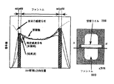
このようなMRI装置においてソレノイド型受信コイルを用いて撮影したファントム画像を例として、本発明による補正処理方法と、原画像にLPFを作用させたものをシェーディングとする従来の補正処理方法とを比較して説明する。図7に示すグラフは、ファントム600のA−A’断面のx方向位置を横軸をとし、信号値を縦軸としたグラフであり、図において当然ながら信号はファントム部分だけであり、原画像のプロファイルは受信コイル700の感度分布(シェーディング)に起因して凹となっている。従来法ではこの原画像に直接LPFを作用させてコイルの感度分布を推定しているので、この場合には、図中点線で示すように被写体のエッジ部分(斜線で示す部分)で感度分布が低くなり、本来の感度分布との差が生じる。これに対し、本発明の補正処理方法では、原画像にエッジフィル処理を行い、被写体の外側に被写体の信号値を等方的に拡張しているため、LPFを作用しても、被写体の周辺では推定感度分布が低下することなく実際の感度分布にほぼ一致している。
【0033】
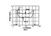
図8は、本発明の補正処理方法により推定された感度分布を用いて、ファントムのMR画像のシェーディングを補正した結果を示すものである。原画像のプロフィアルは不均一性{(最大信号値−最小信号値)/最小信号値=b/a}が0.33であったが、シェーディング補正により、0.11(b’/a’)に改善でき、図9に示すような従来の補正画像におけるエッジの強調は見られない。
【0034】
本発明の補正処理方法は、頸部画像、肩部画像、顎間接画像、頭部画像、脊椎画像等あらゆる部位のMR画像に有効であり、また各種局所コイル、マルチプルコイルのシェーディング補正の有効である。
【0035】
【発明の効果】
以上の説明からわかるように、本発明の補正処理方法によれば、原画像の境界を抽出するとともに、この境界近傍の背景の絵素を等方的に抽出して、信号値を置換する処理(エッジフィル処理)をすることにより、エッジ部分の過補正がなくなり、理想的なシェーディング補正が可能となる。また被写体領域が、等法的に拡張されるので、どの向きに被写体がシェーディングを持っていても、理想的な補正ができ、あらゆる部位、あらゆる角度の被写体にも適用できる。
【図面の簡単な説明】
【図1】本発明の一実施例を示すフロー図。
【図2】図1のフロー図における手段101の処理を説明する図で、(a)は原画像を示す図、(b)は2値化画像を示す図。
【図3】図1のフロー図における手段102の処理を説明する図。
【図4】図1のフロー図における手段103、104の処理を説明する図で、(a)は境界画像からの領域抽出を示す図、(b)及び(c)はそれぞれ境界近傍の背景の絵素値の置換を示す図。
【図5】本発明によるエッジフィルの一実施例を説明する図。
【図6】本発明が適用されるMRI装置の全体概要を示すブロック図。
【図7】本発明の原理を説明する図。
【図8】本発明の補正処理方法による処理の一実施例を示すグラフ。
【図9】従来の補正処理方法による処理を示すグラフ。
【符号の説明】
1・・・・・・CPU(画像処理手段)
2・・・・・・シーケンサ
21・・・・傾斜磁場発生系(磁場発生手段)
3・・・・・・送信系
4・・・・・・静磁場磁石(磁場発生手段)
5・・・・・・受信系
6・・・・・・信号処理系(画像処理手段)
200・・・・・原画像
201・・・・・被写体
202・・・・・背景
300・・・・・2値化画像
400・・・・・境界画像
401・・・・・境界
500・・・・・第2の画像[0001]
BACKGROUND OF THE INVENTION
The present invention relates to a method for correcting shading of a grayscale image, and in particular, a nuclear magnetic resonance (hereinafter referred to as “NMR”) signal from hydrogen, phosphorus, etc. in a subject is measured, and a nuclear density distribution, relaxation time distribution, etc. The present invention relates to an image correction processing method applied to a cross-sectional image of a human body obtained by a nuclear magnetic resonance imaging (MRI) method or the like for imaging the image and an MRI apparatus provided with such image correction processing means.
[0002]
[Prior art]
In MRI, protons, which are the main constituents of the subject, are imaged, and the spatial distribution of proton density and the relaxation phenomenon of excited states are imaged, so that the human head, abdomen, limbs, etc. The form or function is photographed two-dimensionally or three-dimensionally.
[0003]
Although this MRI image is widely used in clinical practice, there is a case where shading due to the apparatus appears strongly. In particular, when a local RF receiving coil is used, there are cases where shading caused by the sensitivity distribution of the receiving coil is remarkable and diagnosis is difficult. For example, the profile of the original image of the phantom shown in FIG. 9 is concave where it should be flat, and reflects the sensitivity distribution of the receiving coil. As means for avoiding this, shading correction has been proposed. As an example, a method has been proposed in which a low-frequency component of an image is extracted, and this is regarded as device-derived shading, and the original image is corrected (Axel et al., “Intensity correction in surface coil MR imaging” American Journal of・ Roentogenology, 148, 418-420, 1987).
[0004]
Although the above method is simple, the low-frequency component extracted from the original image has a deviation from the actual shading in the vicinity of the boundary between the subject and the background. As shown in FIG. 9, there is a defect that the peripheral portion of the subject becomes high brightness in the corrected image as shown in FIG.
[0005]
As a method for solving this problem, a method has been proposed in which a secondary image obtained by replacing the region outside the boundary between the subject and the background with the highest pixel value is extracted, and the low-frequency component of this image is extracted, thereby shading correction is performed. (Wold et al., “Phased Array Detector and Automatic Intensity Correction Algorithm for High-Resolution MR Imaging of the Human Brain,” Magnetic Resonance in Medicine, 34, 433-439, 1995).
[0006]
[Problems to be solved by the invention]
Although this method shows an effect with a cross-sectional image of the head, it cannot be applied to a subject with a complicated shape where the boundary between the subject and the background is complicated, and its application is a simple shape like the head Application to the subject (circular) has stopped. On the other hand, in MRI, since every part is imaged from every angle, the correction algorithm is required to be applied to an arbitrary image, but there is no algorithm that enables this.
[0007]
Accordingly, an object of the present invention is to provide a shading correction algorithm that can be applied to an arbitrary image.
[0008]
[Means for Solving the Problems]
The above problem is an image correction processing method for correcting shading of an original image that is a two-dimensional or three-dimensional gray image having a subject and a background.
And means (101) for segmenting the original image into a subject region and a background region,
And means (102) for extracting boundaries of the object and the background,
And means (103) for extracting picture elements in the vicinity of the boundary isotropically from the original image,
Of the picture element which is the extraction, and means for forming a picture element value of the picture element of the background area, the second image is replaced with the value calculated from the pixel value of the pixel of the subject region (104),
The second image, and means for applying a low pass filter (105),
Wherein it is solved by the image correction processing method and means for correcting the luminance of the original image with the third image after low pass filtering effect (106).
[0009]
By extracting the background near the boundary isotropically, it can be applied to images of all angles. Here, in the case of a two-dimensional image, isotropic extraction means that a pixel area within a square area or a circular area having a specific size with a boundary point as the center is extracted. In the case of a three-dimensional image, a picture element within a cubic region or a spherical region having a specific size centering on the boundary point is extracted.
[0010]
The means for replacing the pixel value of the background picture element with the signal value of the subject calculates the signal value of the subject based on the pixel value of the picture element that is the subject, and obtains this signal value as the background picture value. It is assumed to be an elementary picture element value. In this case, the signal value of the subject may be obtained based on the pixel value of the entire subject, but the average is based on the pixel value of the pixel that is the subject among the isotropically extracted picture elements. It can be obtained by calculating a value or a median value.
[0011]
The image obtained by applying the low-frequency pass filter to the second image obtained by replacing the background picture element in the vicinity of the boundary with the signal value of the subject as described above is substantially the same as the actual shading in the vicinity of the boundary. Since the original processing is isotropic, no matter which direction the original image has shading, the original image is corrected using this image, and ideal correction with overcorrection prevented is performed. be able to.
[0012]
In addition, the MRI apparatus of the present invention irradiates a magnetic field generating means for generating each of a static magnetic field, a gradient magnetic field, and a high-frequency magnetic field, and a high-frequency magnetic field that generates nuclear magnetic resonance in a nuclear spin of a tissue constituting the subject. A sequencer for controlling the magnetism generating means; means for detecting a nuclear magnetic resonance signal generated from the subject; image processing means for signal processing of the nuclear magnetic resonance signal to reconstruct an image; and means for displaying an image. The image processing means includes a shading correction means for executing the image correction processing method.
[0013]
Since the MRI apparatus of the present invention is equipped with such a shading correction means, it can correct the shading of the MR image caused by the sensitivity distribution of the detecting means without overcorrection, and provides an image effective for diagnosis. it can.
[0014]
DETAILED DESCRIPTION OF THE INVENTION
An embodiment of the image correction processing method of the present invention will be described below with reference to the flowchart shown in FIG. FIG. 2A schematically shows an MRI image (original image) 200, where the subject 201 portion is a high-brightness gray image and the
[0015]
In the image correction processing method of the present invention, first, a high luminance area of such a
[0016]
Next, the boundary between the subject 201 and the
[0017]
Next, the picture elements near the boundary of the
[0018]
FIG. 5B shows the
[0019]
The edge fill processing described above is performed over the entire boundary as shown in FIGS. 4B and 4C, and finally the background pixel values are replaced over the entire boundary as shown in FIG. 4C. An image (second image) 500 is obtained. Note that the edge fill processing may be performed for all the picture elements serving as the boundaries, but may be performed discretely.
[0020]
The
[0021]
Finally, the brightness of the
[0022]
In the above description, an example in which the correction processing method of the present invention is applied to a two-dimensional image has been described. However, the present invention can be similarly applied to a three-dimensional image. In this case, after extracting the contour (boundary), a three-dimensional region is isotropically extracted around the boundary picture element, and edge fill processing is performed on this region. Also in this case, edge fill may be performed discretely instead of all the picture elements that are the boundaries.
[0023]
In addition, the isotropically extracted region may be a circular region instead of a square region in the case of two dimensions. In the three-dimensional case, a cubic region or a spherical region can be used.
[0024]
Furthermore, the correction processing method of the present invention can be applied to correction of an image having shading due to the apparatus, but the case where it is applied to image processing in an MRI apparatus will be described below.
[0025]
FIG. 6 is a diagram showing an overall outline of an MRI apparatus to which the present invention is applied. This MRI apparatus is roughly classified into a central processing unit (CPU) 1, a
[0026]
The
[0027]
The
[0028]
The static magnetic
[0029]
The receiving
[0030]
The
[0031]
The
[0032]
Comparison of the correction processing method according to the present invention and the conventional correction processing method using shading that is obtained by applying an LPF to the original image, using a phantom image taken with a solenoid type receiving coil in such an MRI apparatus as an example. To explain. The graph shown in FIG. 7 is a graph in which the horizontal axis represents the x-direction position of the AA ′ cross section of the phantom 600 and the vertical axis represents the signal value. In FIG. This profile is concave due to the sensitivity distribution (shading) of the receiving coil 700. In the conventional method, the LPF is directly applied to the original image to estimate the sensitivity distribution of the coil. In this case, the sensitivity distribution is present at the edge portion of the subject (the portion indicated by the oblique lines) as indicated by the dotted line in the figure. It becomes lower and a difference from the original sensitivity distribution occurs. On the other hand, in the correction processing method of the present invention, edge fill processing is performed on the original image, and the signal value of the subject isotropically expanded outside the subject. Then, the estimated sensitivity distribution does not decrease and almost matches the actual sensitivity distribution.
[0033]
FIG. 8 shows the result of correcting the shading of the phantom MR image using the sensitivity distribution estimated by the correction processing method of the present invention. The profile of the original image had non-uniformity {(maximum signal value−minimum signal value) / minimum signal value = b / a} of 0.33, but it was 0.11 (b ′ / a ′) by shading correction. The edge enhancement in the conventional corrected image as shown in FIG. 9 is not observed.
[0034]
The correction processing method of the present invention is effective for MR images of various parts such as a cervical image, a shoulder image, an indirect jaw image, a head image, and a spine image, and is effective for shading correction of various local coils and multiple coils. is there.
[0035]
【The invention's effect】
As can be seen from the above description, according to the correction processing method of the present invention, the boundary of the original image is extracted, the background picture element near the boundary is extracted isotropically, and the signal value is replaced. By performing (edge fill processing), overcorrection of the edge portion is eliminated, and ideal shading correction can be performed. In addition, since the subject area is expanded isometrically, an ideal correction can be made regardless of the orientation of the subject in any direction, and it can be applied to subjects of any part and any angle.
[Brief description of the drawings]
FIG. 1 is a flowchart showing an embodiment of the present invention.
2A and 2B are diagrams for explaining processing of the
FIG. 3 is a view for explaining processing of
FIGS. 4A and 4B are diagrams for explaining the processing of the
FIG. 5 is a diagram illustrating an embodiment of edge fill according to the present invention.
FIG. 6 is a block diagram showing an overall outline of an MRI apparatus to which the present invention is applied.
FIG. 7 is a diagram illustrating the principle of the present invention.
FIG. 8 is a graph showing an example of processing by the correction processing method of the present invention.
FIG. 9 is a graph showing processing by a conventional correction processing method.
[Explanation of symbols]
1 .... CPU (image processing means)
2 ...
3 ....
5 .... Receiving
200 …… Original image
201 ・ ・ ・ ・ ・ Subject
202 ・ ・ ・ ・ ・ Background
300... Binarized image
400 ... Border image
401: Boundary
500 ... second image
Claims (2)
前記原画像を被写体領域と背景領域とに領域分割する手段(101)と、
前記被写体と前記背景の境界を抽出する手段(102)と、
前記原画像から前記境界の近傍の絵素を等方的に抽出する手段(103)と、
前記抽出された絵素のうち、背景領域の絵素の絵素値を、被写体領域の絵素の絵素値から算出される値で置換し第2の画像を形成する手段(104)と、
前記第2の画像に、低周波通過フィルタを作用させる手段(105)と、
前記低周波通過フィルタ作用後の第3の画像を使って前記原画像の輝度を補正する手段(106)とを含む画像補正処理方法。In an image correction processing method for correcting shading of an original image which is a two-dimensional or three-dimensional gray image having a subject and a background
Means (101) for dividing the original image into a subject area and a background area;
Means (102) for extracting a boundary between the subject and the background;
Means (103) for isotropically extracting picture elements in the vicinity of the boundary from the original image;
Means (104) for forming a second image by replacing a pixel value of a picture element in a background area with a value calculated from a picture element value of a picture element in a subject area among the extracted picture elements;
Means (105) for applying a low-frequency pass filter to the second image;
Means (106) for correcting the luminance of the original image using the third image after the low frequency pass filter action.
前記抽出された絵素のうち、背景領域の絵素の絵素値を、被写体領域の絵素の絵素値から算出される値で置換して第2の画像を形成する手段(Means for forming a second image by replacing a pixel value of a pixel in a background area with a value calculated from a pixel value of a picture element in a subject area among the extracted picture elements ( 104104 )と、前記第2の画像に、低周波通過フィルタを作用させる手段() And means for applying a low-frequency pass filter to the second image ( 105105 )と、前記低周波通過フィルタ作用後の第3の画像を使って前記原画像の輝度を補正する手段() And means for correcting the luminance of the original image using the third image after the action of the low-frequency pass filter ( 106106 )とを含むシェーディング補正手段を備えたことを特徴とする磁気共鳴イメージング装置。And a shading correction means including a magnetic resonance imaging apparatus.
Priority Applications (1)
| Application Number | Priority Date | Filing Date | Title |
|---|---|---|---|
| JP31068996A JP3689509B2 (en) | 1996-11-21 | 1996-11-21 | Image correction processing method |
Applications Claiming Priority (1)
| Application Number | Priority Date | Filing Date | Title |
|---|---|---|---|
| JP31068996A JP3689509B2 (en) | 1996-11-21 | 1996-11-21 | Image correction processing method |
Publications (2)
| Publication Number | Publication Date |
|---|---|
| JPH10146325A JPH10146325A (en) | 1998-06-02 |
| JP3689509B2 true JP3689509B2 (en) | 2005-08-31 |
Family
ID=18008284
Family Applications (1)
| Application Number | Title | Priority Date | Filing Date |
|---|---|---|---|
| JP31068996A Expired - Fee Related JP3689509B2 (en) | 1996-11-21 | 1996-11-21 | Image correction processing method |
Country Status (1)
| Country | Link |
|---|---|
| JP (1) | JP3689509B2 (en) |
Cited By (1)
| Publication number | Priority date | Publication date | Assignee | Title |
|---|---|---|---|---|
| US10775469B2 (en) | 2018-04-23 | 2020-09-15 | Canon Medical Systems Corporation | Magnetic resonance imaging apparatus and method |
Families Citing this family (5)
| Publication number | Priority date | Publication date | Assignee | Title |
|---|---|---|---|---|
| DE102004061507B4 (en) * | 2004-12-21 | 2007-04-12 | Siemens Ag | Method for correcting inhomogeneities in an image and imaging device therefor |
| KR101165841B1 (en) | 2005-06-30 | 2012-07-17 | 엘지디스플레이 주식회사 | Display Apparatus |
| JP5248010B2 (en) * | 2006-02-17 | 2013-07-31 | 株式会社東芝 | Data correction apparatus, data correction method, magnetic resonance imaging apparatus, and X-ray CT apparatus |
| CN100591269C (en) * | 2006-02-17 | 2010-02-24 | 株式会社东芝 | Data correction apparatus, data correction method, magnetic resonance imaging apparatus and X-ray CT apparatus |
| KR101348601B1 (en) * | 2008-01-31 | 2014-01-16 | 삼성전자주식회사 | System and method for immersive enhancement according to adaptive immersive enhancement prediction |
-
1996
- 1996-11-21 JP JP31068996A patent/JP3689509B2/en not_active Expired - Fee Related
Cited By (1)
| Publication number | Priority date | Publication date | Assignee | Title |
|---|---|---|---|---|
| US10775469B2 (en) | 2018-04-23 | 2020-09-15 | Canon Medical Systems Corporation | Magnetic resonance imaging apparatus and method |
Also Published As
| Publication number | Publication date |
|---|---|
| JPH10146325A (en) | 1998-06-02 |
Similar Documents
| Publication | Publication Date | Title |
|---|---|---|
| JP3976684B2 (en) | Method and apparatus for reducing the effects of motion in images | |
| US8358822B2 (en) | Automatic determination of field of view in cardiac MRI | |
| CN106780649B (en) | Image artifact removing method and device | |
| US11747424B2 (en) | Magnetic resonance imaging apparatus, image processing apparatus, and image processing method | |
| AU6350399A (en) | Imaging | |
| US10748309B2 (en) | Magnetic resonance imaging with enhanced bone visualization | |
| US20090219021A1 (en) | Method and apparatus for removing artifacts during magnetic resonance imaging | |
| US10845445B2 (en) | Magnetic resonance imaging apparatus and medical image processing apparatus | |
| US20230260088A1 (en) | Medical information processing apparatus and medical information processing method | |
| JP3689509B2 (en) | Image correction processing method | |
| JP6647836B2 (en) | Magnetic resonance imaging apparatus, image processing apparatus, and image processing method | |
| JP3865887B2 (en) | Image correction method | |
| JP2006255046A (en) | Magnetic resonance imaging method and image processing apparatus | |
| JP7179483B2 (en) | Magnetic resonance imaging device | |
| JP5105823B2 (en) | Magnetic resonance imaging apparatus, medical image processing method, program, and medical image display system | |
| JP3576069B2 (en) | MRI equipment | |
| JP2020171693A (en) | Medical information processing device and medical information processing method | |
| US20240005480A1 (en) | Methods and systems for automated saturation band placement | |
| JP2932175B2 (en) | MRI equipment | |
| US20230136320A1 (en) | System and method for control of motion in medical images using aggregation | |
| CN112782629B (en) | Magnetic resonance scanning control method, storage medium and system | |
| JP2007202584A (en) | Magnetic resonance imaging apparatus | |
| JP2009273501A (en) | Magnetic resonance imaging system, image reconstituting method and program | |
| Weisenseel et al. | A variational approach to multi-modality subsurface data inversion and fusion based on shared image structure | |
| JP3600656B2 (en) | Image processing method and magnetic resonance imaging apparatus |
Legal Events
| Date | Code | Title | Description |
|---|---|---|---|
| A977 | Report on retrieval |
Free format text: JAPANESE INTERMEDIATE CODE: A971007 Effective date: 20050523 |
|
| TRDD | Decision of grant or rejection written | ||
| A01 | Written decision to grant a patent or to grant a registration (utility model) |
Free format text: JAPANESE INTERMEDIATE CODE: A01 Effective date: 20050607 |
|
| A61 | First payment of annual fees (during grant procedure) |
Free format text: JAPANESE INTERMEDIATE CODE: A61 Effective date: 20050613 |
|
| R150 | Certificate of patent or registration of utility model |
Free format text: JAPANESE INTERMEDIATE CODE: R150 |
|
| FPAY | Renewal fee payment (event date is renewal date of database) |
Free format text: PAYMENT UNTIL: 20090617 Year of fee payment: 4 |
|
| FPAY | Renewal fee payment (event date is renewal date of database) |
Free format text: PAYMENT UNTIL: 20090617 Year of fee payment: 4 |
|
| FPAY | Renewal fee payment (event date is renewal date of database) |
Free format text: PAYMENT UNTIL: 20100617 Year of fee payment: 5 |
|
| FPAY | Renewal fee payment (event date is renewal date of database) |
Free format text: PAYMENT UNTIL: 20110617 Year of fee payment: 6 |
|
| FPAY | Renewal fee payment (event date is renewal date of database) |
Free format text: PAYMENT UNTIL: 20110617 Year of fee payment: 6 |
|
| FPAY | Renewal fee payment (event date is renewal date of database) |
Free format text: PAYMENT UNTIL: 20120617 Year of fee payment: 7 |
|
| FPAY | Renewal fee payment (event date is renewal date of database) |
Free format text: PAYMENT UNTIL: 20120617 Year of fee payment: 7 |
|
| FPAY | Renewal fee payment (event date is renewal date of database) |
Free format text: PAYMENT UNTIL: 20130617 Year of fee payment: 8 |
|
| LAPS | Cancellation because of no payment of annual fees |