JP3679535B2 - Colonoscopy insertion practice device - Google Patents
Colonoscopy insertion practice device Download PDFInfo
- Publication number
- JP3679535B2 JP3679535B2 JP01531097A JP1531097A JP3679535B2 JP 3679535 B2 JP3679535 B2 JP 3679535B2 JP 01531097 A JP01531097 A JP 01531097A JP 1531097 A JP1531097 A JP 1531097A JP 3679535 B2 JP3679535 B2 JP 3679535B2
- Authority
- JP
- Japan
- Prior art keywords
- large intestine
- model
- colon
- endoscope insertion
- endoscope
- Prior art date
- Legal status (The legal status is an assumption and is not a legal conclusion. Google has not performed a legal analysis and makes no representation as to the accuracy of the status listed.)
- Expired - Lifetime
Links
Images


Landscapes
- Endoscopes (AREA)
Description
【0001】
【発明の属する技術分野】
本発明は、人体の大腸内への内視鏡の挿入技術を習得するための大腸内視鏡挿入練習装置に関する。
【0002】
【従来の技術】
一般に、人体内の大腸は、内視鏡検査を行なうことのできる他の臓器に比べて形状が複雑であるため、この大腸に内視鏡を挿入するには高度な技術が要求される。そこで、従来から大腸内視鏡の挿入技術をマスターする為に、内視鏡を挿入することのできる人体内の大腸モデル(コロンモデル)を備えた大腸内視鏡挿入練習装置が開発されている。
【0003】
この種の大腸内視鏡挿入練習装置として例えば実公昭60−32695号公報には内視鏡を挿入することのできる大腸モデルを取付板に着脱可能に取付けることにより、大腸モデルの洗浄を容易に行えるようにした構成が示されている。
【0004】
【発明が解決しようとする課題】
上記従来構成の大腸内視鏡挿入練習装置では取付板には標準的な形態の常に同じ大腸モデルが取付けられている。そのため、従来の大腸内視鏡挿入練習装置では標準的な形態の大腸モデルによる大腸内視鏡の挿入練習しか経験できない問題がある。
【0005】
しかしながら、一般に、人体内の大腸の形態、例えば大腸の形状、大きさ、硬さ、癒着状態、大腸の内壁面の襞の状態等は患者毎に個人差があるので、医療現場で実際に大腸内視鏡を挿入する際の人体内の大腸の形態は大腸内視鏡挿入練習装置で練習した大腸モデルとは異なることが多い。そのため、従来の大腸内視鏡挿入練習装置では患者の個体差に対応できないので、様々な患者の大腸の形態に対応できる程度に大腸内視鏡の挿入練習を経験することは困難なものとなる問題がある。
【0006】
なお、大腸内視鏡の挿入技術の上達は、いかに様々な患者の大腸の形態に対応できるかということと密接に結びつくので、様々な患者の大腸の形態を再現できる大腸内視鏡挿入練習装置の実用化が要望されているのが実情である。
【0007】
本発明は上記事情に着目してなされたもので、その目的は、様々な患者の大腸の形態を再現でき、患者の個体差に対応して様々な患者の大腸の形態で大腸内視鏡の挿入練習を経験することができ、大腸内視鏡の挿入技術の上達を図るうえで有効な大腸内視鏡挿入練習装置を提供することにある。
【0008】
【課題を解決するための手段】
請求項1の発明は内視鏡を挿入することのできる大腸モデルを取付板に設けるようにした大腸内視鏡挿入練習装置において、同一の大腸モデルを複数種類の形態に付勢することにより前記大腸モデルの形態を変更する付勢手段を設けたことを特徴とする大腸内視鏡挿入練習装置である。
請求項2の発明は前記付勢手段は、前記取付板に対して前記大腸モデルの所定部位の移動および固定が可能であることを特徴とする請求項1記載の大腸内視鏡挿入練習装置である。
請求項3の発明は前記付勢手段は、標準的な人体の大腸の形態を再現する基準位置に設定可能であることを特徴とする請求項1または2に記載の大腸内視鏡挿入練習装置である。
請求項4の発明は前記付勢手段は、同一の取付板に異なる大腸モデルを着脱自在にしたことを特徴とする請求項1から3のいずれかに記載の大腸内視鏡挿入練習装置である。
請求項5の発明は上記大腸モデルの一部を分割して着脱自在としたことを特徴とする請求項4に記載の大腸内視鏡挿入練習装置である。
請求項6の発明は上記付勢手段は、同一の取付板に取付けた大腸モデルの硬さを調整することを特徴とする請求項1に記載の大腸内視鏡挿入練習装置である。
請求項7の発明は前記大腸モデルの伸縮量を検出する検出手段と、前記検出手段による検出結果に基づき、警告する警告手段と、を備えたことを特徴とする請求項1から6のいずれかに記載の大腸内視鏡挿入練習装置である。
【0009】
【発明の実施の形態】
以下、本発明の第1の実施の形態を図1および図2(A)〜(C)を参照して説明する。図1は本実施の形態の大腸内視鏡挿入練習装置1全体の概略構成を示すものである。
【0010】
本実施の形態の大腸内視鏡挿入練習装置1には図1に示すように取付板2と、この取付板2上に取着された大腸モデル3とが設けられている。この大腸モデル3は例えばゴムや樹脂材料などの伸縮自在で気密な弾性膜によって実物と同じように形成されている。
【0011】
すなわち、この大腸モデル3には直腸部4、S字結腸部5、下行結腸部6、脾湾曲部7、横行結腸部8、肝湾曲部9、上行結腸部10、盲腸部11が順次形成されている。また、盲腸部11には虫垂部12および回腸末端部13がそれぞれ突設されている。さらに、直腸部4の下端部には肛門部14が形成されている。
【0012】
また、この大腸モデル3の直腸部4は直腸固定板15上に固定されている。この直腸固定板15は取付板2の一端部、図1中で取付板2の下端部中央部位に固定されている。
【0013】
さらに、大腸モデル3の下行結腸部6および脾湾曲部7は平板状の第1の位置調整板16上に固定されている。この第1の位置調整板16の上下の両端部にはねじ挿入穴がそれぞれ形成され、このねじ挿入穴に固定ねじ17がそれぞれ挿入されている。
【0014】
また、大腸モデル3の肝湾曲部9、上行結腸部10、盲腸部11は平板状の第2の位置調整板18上に固定されている。この第2の位置調整板18の上下の両端部には第1の位置調整板16と同様にねじ挿入穴がそれぞれ形成され、このねじ挿入穴に固定ねじ17がそれぞれ挿入されている。
【0015】
さらに、取付板2の図1中で右端部には第1の位置調整板16の取付け位置を図1中で上下方向に調整する複数のねじ穴19aが上下方向に並設されている。これらのねじ穴19aには第1の位置調整板16の上下の固定ねじ17が適宜選択的に螺着され、取付板2に対する第1の位置調整板16の取付け位置を図1中で上下方向に調整可能になっている。
【0016】
また、取付板2の上下の2か所には第1の位置調整板16の取付け位置を図1中で左右方向に調整する複数のねじ穴19bがそれぞれ左右方向に並設されている。ここで、上下2か所のねじ穴19bの列間の間隔は第1の位置調整板16の上下の固定ねじ17のねじ挿入穴間の間隔と等間隔に設定されている。そして、これらのねじ穴19bには第1の位置調整板16の上下の固定ねじ17が適宜選択的に螺着され、取付板2に対する第1の位置調整板16の取付け位置を図1中で左右方向に調整可能になっている。
【0017】
さらに、取付板2の図1中で左端部には第1の位置調整板16と同様に第2の位置調整板18の取付け位置を図1中で上下方向に調整する複数のねじ穴19cが上下方向に並設されているとともに、この第2の位置調整板18の取付け位置を図1中で左右方向に調整する複数のねじ穴19dが上下2か所でそれぞれ左右方向に並設されている。そして、第2の位置調整板18の上下の固定ねじ17がいずれかの位置のねじ穴19cに適宜選択的に螺着されることにより、取付板2に対する第2の位置調整板18の取付け位置を図1中で上下方向に調整可能になっている。ここで、第2の位置調整板18の上下の固定ねじ17がいずれかの位置のねじ穴19dに適宜選択的に螺着されることにより、取付板2に対する第2の位置調整板18の取付け位置を図1中で左右方向に調整可能になっている。
【0018】
したがって、本実施の形態の大腸内視鏡挿入練習装置1では第1の位置調整板16の取付け位置を図1中で上下方向、或いは左右方向に調整するとともに、同様に第2の位置調整板18の取付け位置を図1中で上下方向、或いは左右方向に調整することにより、大腸モデル3の形状を任意の形状に変更することができ、これにより複数種類の患者の大腸の状態を再現する大腸モデル形態変更手段20が形成されている。
【0019】
また、取付板2上には人体の小腸に相当するクッションとなる小腸ダミー21と、S字結腸部5の動きを規制する腸間膜に相当するS字結腸規制体22と、横行結腸部8の動きを規制する腸間膜に相当する横行結腸規制体23とが設けられている。ここで、小腸ダミー21は例えばゴムや樹脂材料などの伸縮自在な弾性体によって形成されている。さらに、S字結腸規制体22には取付板2上に固定された押え部材24と、一端部がこの押え部材24に固定され、他端部がS字結腸部5に固定された膜体25とが設けられている。同様に、横行結腸規制体23には取付板2上に固定された押え部材26と、一端部がこの押え部材26に固定され、他端部が横行結腸部8に固定された膜体27とが設けられている。
【0020】
また、図1中で、28は本実施の形態の大腸内視鏡挿入練習装置1の挿入練習で使用される大腸用の内視鏡を示すものである。この内視鏡28には体内に挿入される細長い挿入部29と、この挿入部29の基端部に連結された手元側の操作部30とが設けられている。さらに、内視鏡28の挿入部29には細長い可撓管部29aと、この挿入部29の最先端に配設された先端硬性部29bと、この先端硬性部29bと可撓管部29aとの間に配設された湾曲部29cとが設けられている。ここで、挿入部29の湾曲部29cは操作部30によって例えば上下左右の4方向に湾曲操作され、先端硬性部29bの向きが変えられるようになっている。そして、この内視鏡28の挿入部29の挿入操作と、湾曲部29cの湾曲操作との組み合わによって、内視鏡28の挿入部29が後述するごとく挿入練習装置1の大腸モデル3の内腔に挿入されるようになっている。
【0021】
また、操作部30にはユニバーサルコード31の一端部が連結されている。このユニバーサルコード31の他端部には光源装置32に接続されるコネクタ33が設けられている。さらに、コネクタ33には接続コード34の一端部が連結されている。この接続コード34の他端部は第2のコネクタ35を介してビデオプロセッサ36に接続されている。このビデオプロセッサ36にはTVモニタ37が接続されている。
【0022】
そして、内視鏡28の使用時には光源装置32から出射される照明光が図示しないライトガイドファイバを通して内視鏡28の挿入部29の先端部側に導かれ、挿入部29の先端硬性部29bの照明窓から外部に照射されるようになっている。さらに、挿入部29の先端硬性部29bの観察窓から入射された内視鏡28の観察像は先端硬性部29bに組み込まれたCCD等の固体撮像素子によって電気信号に変換され、ビデオプロセッサ36に供給された後、このビデオプロセッサ36からの出力信号がTVモニタ37に入力され、TVモニタ37に表示されるようになっている。
【0023】
次に、上記構成の作用について説明する。本実施の形態の大腸内視鏡挿入練習装置1の使用時には予め大腸モデル形態変更手段20によって大腸モデル3を所望の形態に変更して望みの患者の大腸の状態を再現する作業が行われる。この作業時には取付板2上の第1の位置調整板16の取付け位置と、第2の位置調整板18の取付け位置とがそれぞれ所望の位置に調整される。
【0024】
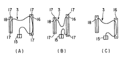
例えば、第1の位置調整板16の取付け位置と、第2の位置調整板18の取付け位置とがそれぞれ図1に示す基準位置に設定された場合には取付板2上の大腸モデル3に図2(A)に示すように標準的な人体の大腸の形態が再現される。
【0025】
また、図2(B)に示すように第1の位置調整板16の取付け位置と、第2の位置調整板18の取付け位置との間の間隔が図1の基準位置よりも小さくなるように設定された場合には取付板2上の大腸モデル3に標準的な体形の人体よりも痩せた体形の人体の大腸の形態が再現される。
【0026】
さらに、図2(C)に示すように第1の位置調整板16の取付け位置に比べて第2の位置調整板18の取付け位置が高くなるように設定された場合には取付板2上の大腸モデル3に肝湾曲部9が脾湾曲部7よりも高くなる状態で配置された大腸の形態が再現される。
【0027】
また、大腸内視鏡挿入練習装置1の大腸モデル3を所望の形態に変更して望みの患者の大腸の状態を再現したのち、大腸モデル3の肛門部14から内視鏡28の挿入部29を大腸モデル3の内腔に挿入して挿入練習が行なわれる。このとき、内視鏡28の挿入部29の挿入操作と、湾曲部29cの湾曲操作との組み合わによって、内視鏡28の挿入部29を大腸モデル3の内腔に挿入する操作が行われる。
【0028】
そこで、上記構成の本実施の形態にあっては次の効果を奏する。すなわち、本実施の形態では取付板2に第1の位置調整板16の取付け位置を図1中で上下方向に調整する複数のねじ穴19aと、第1の位置調整板16の取付け位置を図1中で左右方向に調整する上下2か所の複数のねじ穴19bとを設けるとともに、第2の位置調整板18の取付け位置を図1中で上下方向に調整する複数のねじ穴19cと、この第2の位置調整板18の取付け位置を図1中で左右方向に調整する上下2か所の複数のねじ穴19dとを設け、第1の位置調整板16の上下の固定ねじ17と、第2の位置調整板18の上下の固定ねじ17とによって取付板2上の第1の位置調整板16の取付け位置と、第2の位置調整板18の取付け位置とをそれぞれ所望の位置に調整できるようにしたので、所望の患者の大腸の状態を再現するように大腸モデル3の形態を任意に変更することができる。そのため、単一の大腸内視鏡挿入練習装置1の取付板2上の大腸モデル3に様々な患者の大腸の形態を再現することができるので、患者の個体差に対応して様々な患者の大腸の形態で大腸内視鏡の挿入練習を経験することができ、大腸内視鏡の挿入技術の上達を図るうえで有効である。
【0029】
また、図3(A)〜(G)は本発明の第2の実施の形態を示すものである。図3(A)は本実施の形態の大腸内視鏡挿入練習装置41全体の概略構成を示すものである。
【0030】
本実施の形態の大腸内視鏡挿入練習装置41には図3(A)に示すように取付板42と、この取付板42上に取着された大腸モデル43とが設けられている。この大腸モデル43には第1の実施の形態(図1および図2(A)〜(C)参照)の大腸モデル3と同様に直腸部44、S字結腸部45、下行結腸部46、脾湾曲部47、横行結腸部48、肝湾曲部49、上行結腸部50、盲腸部51が順次形成されている。また、盲腸部51には虫垂部52および回腸末端部53がそれぞれ突設されている。さらに、直腸部44の下端部には肛門部54が形成されている。
【0031】
また、この大腸モデル43の直腸部44、下行結腸部46、脾湾曲部47、肝湾曲部49、上行結腸部50、盲腸部51は取付板42上にそれぞれ直接固定されている。さらに、この大腸モデル43の外周面には複数のフック取付け部55が突設されている。各フック取付け部55には取付け穴56が形成されている。
【0032】
また、取付板42の上には第1の実施の形態の押え部材24と対応する位置に第1の押え部材57が固定されている。この第1の押え部材57には大腸モデル43のフック取付け部55と同様の3つのフック取付け部58が設けられている。ここで、第1の押え部材57におけるS字結腸部45との対向面側には左右両端部に上記フック取付け部58がそれぞれ突設され、横行結腸部48との対向面側には1つのフック取付け部58が突設されている。そして、各フック取付け部58には取付け穴59がそれぞれ形成されている。
【0033】
さらに、取付板42の上には第1の実施の形態の押え部材26と対応する位置に第2の押え部材60が固定されている。この第2の押え部材60には2つのフック取付け部61が設けられている。これらのフック取付け部61は第2の押え部材60における横行結腸部48との対向面側の両端部にそれぞれ突設されている。そして、これらのフック取付け部61には取付け穴62がそれぞれ形成されている。
【0034】
また、取付板42の上には複数、本実施の形態では4つのフック取付け具63が固定されている。ここで、各フック取付け具63は直腸部44の両側部位、横行結腸部48と上行結腸部50との間の角部近傍部位、および横行結腸部48と下行結腸部46との間の角部近傍部位にそれぞれ配置されている。そして、各フック取付け具63には取付け穴64がそれぞれ形成されている。
【0035】
また、本実施の形態の大腸内視鏡挿入練習装置41には複数種類、本実施の形態では図3(B)〜(E)に示す4種類の連結具66A〜66Dが予め設けられている。ここで、図3(B)に示す第1の連結具66Aには例えばコイルバネ、或いはゴム等の弾性体67と、この弾性体67の両端部に固定されたフック68とが設けられている。さらに、図3(C)に示す第2の連結具66Bには第1の連結具66Aよりも長さが短い弾性体69と、この弾性体69の両端部に固定されたフック70とが設けられている。また、図3(D)に示す第3の連結具66Cは一対のフック71が連結されて形成されている。
【0036】
さらに、図3(E)に示す第4の連結具66Dは第1の連結具66Aと同様に弾性体67と、この弾性体67の両端部に固定されたフック68とが設けられている。また、弾性体67の外周面には例えば歪ゲージなどの歪み検知器72が取付けられている。この歪み検知器72は信号線73を介して歪み量検出装置74に接続されている。この歪み量検出装置74には歪み検知器72から出力される検出信号に基いて患者の苦痛の程度を判断する制御手段と、例えば患者の苦痛の程度がある値を越えると警告音を出す警報装置とが組み込まれている。
【0037】
なお、歪み量検出装置74は必ずしも本実施の形態の大腸内視鏡挿入練習装置41に一体的に組み込まれている必要はなく、大腸内視鏡挿入練習装置41とは別体の歪み量検出装置74を必要に応じて大腸内視鏡挿入練習装置41に接続する構成にしてもよい。
【0038】
そして、本実施の形態の大腸内視鏡挿入練習装置41では図3(B)〜(E)に示す複数種類の連結具66A〜66Dのうち実際に使用する連結具の種類と、その取付け位置とを任意に選択することにより、大腸モデル3の形状を任意の形状に変更することができ、これにより複数種類の患者の大腸の状態を再現する大腸モデル形態変更手段75が形成されている。
【0039】
次に、上記構成の作用について説明する。本実施の形態の大腸内視鏡挿入練習装置41の大腸モデル43を所望の形態に変更する作業時には大腸モデル形態変更手段75が次の通り使用される。
【0040】
例えば、図3(A)に示すように第1の押え部材57のフック取付け部58とS字結腸部45のフック取付け部55との間に2つの第2の連結具66Bが架設されるとともに、第2の押え部材60のフック取付け部61と横行結腸部48のフック取付け部55との間に2つの第1の連結具66Aが架設された場合には取付板42上の大腸モデル43に標準的な人体の大腸の形態が再現される。
【0041】
また、図3(A)の標準的な形態の大腸モデル43の横行結腸部48のフック取付け部55と上行結腸部50のフック取付け部55との間の角部に第3の連結具66Cを取付けることにより、図3(F)に示すように横行結腸部48と上行結腸部50との間が癒着した状態の大腸の形態が再現される。
【0042】
さらに、図3(A)の標準的な形態の大腸モデル43の第1の押え部材57のフック取付け部58とS字結腸部45のフック取付け部55との間の2つの第2の連結具66Bを取り外した状態で、図3(G)に示すように直腸部44の左側のフック取付け具63とS字結腸部45のフック取付け部55との間に第2の連結具66Bが架設された場合にはS字結腸部45がα状に変形された状態の大腸の形態が再現される。
【0043】
そこで、上記構成の本実施の形態にあっては次の効果を奏する。すなわち、本実施の形態では図3(B)〜(E)に示す複数種類の連結具66A〜66Dのうち実際に使用する連結具の種類と、その取付け位置とを任意に選択することにより、大腸モデル3の形状を任意の形状に変更することができ、これにより複数種類の患者の大腸の状態を再現する大腸モデル形態変更手段75を形成したので、所望の患者の大腸の状態を再現するように大腸モデル43の形態を任意に変更することができる。そのため、単一の大腸内視鏡挿入練習装置41の取付板42上の大腸モデル43に様々な患者の大腸の形態を再現することができるので、患者の個体差に対応して様々な患者の大腸の形態で大腸内視鏡の挿入練習を経験することができ、大腸内視鏡の挿入技術の上達を図るうえで有効である。
【0044】
さらに、本実施の形態では図3(E)に示す第4の連結具66Dの弾性体67の外周面に歪み検知器72を取付けたので、第4の連結具66DをS状結腸部45や、横行結腸部48の腸間膜に相当するような伸縮性のバンドとして使用することにより、大腸内視鏡の挿入練習中に大腸モデル43の伸縮量を検出し、それがある値を越えると歪み量検出装置74の警報装置から警告音を出すことができる。そのため、患者の苦痛を無視して大腸内視鏡を無理矢理押し込むことを防止して患者の苦痛を考慮した大腸内視鏡の挿入練習ができるので、大腸内視鏡の挿入技術の上達を図るうえで一層有効である。
【0045】
また、図4は本発明の第3の実施の形態の大腸内視鏡挿入練習装置81全体の概略構成を示すものである。本実施の形態の大腸内視鏡挿入練習装置81は第1の実施の形態(図1および図2(A)〜(C)参照)の大腸内視鏡挿入練習装置1の取付板2を上面が開口された略箱型のケース82によって形成するとともに、このケース82の上面開口部を閉塞するカバー83に人体の腹部に相当するクッションとなる腹部ダミー84を着脱可能に取付けたものである。
【0046】
さらに、カバー83は人体の皮膚に相当する例えばビニールや、ゴムなどの弾性体によって形成されている。そして、このカバー83の一端部がケース82の上面開口部の一端部にヒンジ結合部を介して開閉可能に連結されている。
【0047】
また、カバー83の他端部(自由端部)には左右一対の係合突起85が突設されている。さらに、ケース82の上面開口部の周縁部位にはカバー83のヒンジ結合部とは反対側の端部にカバー83の係合突起85と係脱可能に係合する係合穴86が形成されている。また、図4中で、87はケース82の取手である。
【0048】
さらに、本実施の形態では小腸ダミー21や、横行結腸規制体23や、腹部ダミー84は予め複数種類設けられており、必要に応じて所望の形態の小腸ダミー21や、横行結腸規制体23や、腹部ダミー84が着脱交換可能に取付けられるようになっている。なお、それ以外の部分の構成は第1の実施の形態と同様であり、図4中で、第1の実施の形態と同一部分には同一の符号を付し、ここではその説明を省略する。
【0049】
そこで、上記構成の本実施の形態の大腸内視鏡挿入練習装置81にあっても第1の実施の形態と同様の操作で大腸モデル3を所望の形態に変更することができるので、第1の実施の形態と同様に患者の個体差に対応して様々な患者の大腸の形態で大腸内視鏡の挿入練習を経験することができ、大腸内視鏡の挿入技術の上達を図るうえで有効である。
【0050】
さらに、本実施の形態では特に、カバー83によってケース82の上面開口部が閉塞され、カバー83の係合突起84がケース82の係合穴85に係合された状態ではカバー83の腹部ダミー84が大腸モデル3を圧迫するようになっているので、腹部ダミー84の大きさに応じて大腸モデル3に太った人体や、痩せた人体の大腸の状態を再現することができる。そのため、大腸モデル3の形態変更の種類をさらに増加させることができる効果がある。
【0051】
また、図5は本発明の第4の実施の形態を示すものである。本実施の形態は例えば第1の実施の形態(図1および図2(A)〜(C)参照)の大腸内視鏡挿入練習装置1における大腸モデル3のS字結腸部5や、横行結腸部8のように比較的動きやすく自由度の高い部分に加温板91を取付け、この加温板91に電気コード92を介して温度制御用のコントローラ93を接続したものである。
【0052】
そこで、上記構成の本実施の形態にあっては、コントローラ93によって加温板91の温度制御を行うことにより、S字結腸部5や、横行結腸部8の硬さを調整することができる。ここで、例えば加温板91の非加熱時にはS字結腸部5や、横行結腸部8の弾性体の材料の硬さを比較的硬い緊張状態で保持させることができる。そして、加温板91を加熱することにより、S字結腸部5や、横行結腸部8の弾性体の材料を柔らかい弛緩状態に変化させることができる。そのため、本実施の形態でも大腸モデル3の形態変更の種類をさらに増加させることができる効果がある。
【0053】
また、図6および図7(A)〜(E)は本発明の第5の実施の形態を示すものである。本実施の形態は第1の実施の形態(図1および図2(A)〜(C)参照)の大腸内視鏡挿入練習装置1における大腸モデル3の直腸固定板15を固定ねじ101によって取付板2に着脱可能に取付けるとともに、予め複数種類、本実施の形態では図7(A)〜(E)に示す5種類の大腸モデルユニット102A〜102Eを設け、必要に応じていずれかの大腸モデルユニットを適宜選択的に取付板2に着脱可能に取付ける構成にしたものである。
【0054】
ここで、図7(A)は標準体形の人体の大腸モデル3を示す第1の大腸モデルユニット102Aである。さらに、図7(B)は大腸モデル3全体が弛緩された状態の第2の大腸モデルユニット102B、図7(C)は標準的な大腸モデル3よりもS字結腸部5および横行結腸部8が長い状態の第3の大腸モデルユニット102C、図7(D)はS字結腸部5および肝湾曲部9の部分にそれぞれ癒着が発生した状態の第4の大腸モデルユニット102D、図7(E)は大腸モデル3全体が異形状に変形された第5の大腸モデルユニット102Eをそれぞれ示すものである。
【0055】
そこで、上記構成の本実施の形態にあっては、必要に応じて図7(A)〜(E)の5種類の大腸モデルユニット102A〜102Eのいずれかを適宜選択的に取付板2に着脱可能に取付けることにより、取付板2上の大腸モデル3の形態を任意に変更することができる。そのため、単一の大腸内視鏡挿入練習装置1の取付板2上に様々な患者の大腸の形態を再現することができるので、患者の個体差に対応して様々な患者の大腸の形態で大腸内視鏡の挿入練習を経験することができ、大腸内視鏡の挿入技術の上達を図るうえで有効である。
【0056】
また、図8〜図11は本発明の第6の実施の形態を示すものである。図8は本実施の形態の内視鏡挿入練習装置111全体の概略構成を示すものである。本実施の形態では第1の実施の形態(図1および図2(A)〜(C)参照)の大腸内視鏡挿入練習装置1における大腸モデル3が直腸部112と、S字結腸ユニット113と、下行結腸部114と、脾湾曲部115と横行結腸部116と肝湾曲部117とを一体化した横行結腸ユニット118と、上行結腸部119と盲腸部120とを一体化した上行結腸ユニット121とに5分割されている。そして、第1の実施の形態の取付板2上には直腸部112と、下行結腸部114と、上行結腸ユニット121とが固定されている。
【0057】
また、横行結腸ユニット118は予め複数種類、本実施の形態では図9(A)〜(E)に示す5種類の横行結腸ユニット118A〜118Eが設けられている。さらに、S字結腸ユニット113は予め複数種類、本実施の形態では図10(A)〜(F)に示す6種類のS字結腸ユニット113A〜113Fが設けられている。
【0058】
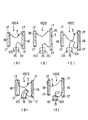
ここで、図9(A)は標準形の横行結腸を示す第1の横行結腸ユニット118Aである。さらに、図9(B)は弛緩された状態の第2の横行結腸ユニット118B、図9(C)は標準的な大腸モデル3よりも横行結腸部8が長い状態の第3の横行結腸ユニット118C、図9(D)は横行結腸部8と肝湾曲部9との間の部分に癒着が発生した状態の第4の横行結腸ユニット118D、図9(E)は全体が異形状に変形された第5の横行結腸ユニット118Eをそれぞれ示すものである。
【0059】
また、図10(A)は標準形の第1のS字結腸ユニット113A、図10(B)は弛緩された状態の第2のS字結腸ユニット113B、図10(C)はS字結腸部5がα状に変形された状態の第3のS字結腸ユニット113C、図10(D)は標準的な大腸モデル3よりもS字結腸部5が長い状態の第4のS字結腸ユニット113D、図10(E)はS字結腸部5と直腸部4との連結部の部分に癒着が発生した状態の第5のS字結腸ユニット113E、図10(F)はS字結腸部5と下行結腸部6との連結部の部分に癒着が発生した状態の第6のS字結腸ユニット113Fをそれぞれ示すものである。
【0060】
そして、本実施の形態では取付板2上に固定された直腸部112と、下行結腸部114との間に図10(A)〜(F)に示す6種類のS字結腸ユニット113A〜113Fのいずれかが適宜選択的に取付けられるとともに、取付板2上に固定された下行結腸部114と、上行結腸ユニット121との間に図9(A)〜(E)に示す5種類の横行結腸ユニット118A〜118Eのいずれかが適宜選択的に取付けられるようになっている。ここで、直腸部112および下行結腸部114とS字結腸ユニット113との連結部や、下行結腸部114および上行結腸ユニット121と横行結腸ユニット118との連結部は例えばマジックテープ等の嵌合固定具122を介して係脱可能に連結されている。
【0061】
なお、図11に示すように図10(A)〜(F)に示す各S字結腸ユニット113A〜113FのS字結腸本体123の内壁面に突設された襞124の長さや、硬さなどの条件を変化させた複数種類のS字結腸ユニットをさらに設け、必要に応じてこのS字結腸ユニットを適宜選択的に取付板2に着脱可能に取付ける構成にしてもよい。
【0062】
そこで、上記構成の本実施の形態にあっては、必要に応じて図9(A)〜(E)に示す5種類の横行結腸ユニット118A〜118Eや、図11のS字結腸ユニットおよび図10(A)〜(F)に示す6種類のS字結腸ユニット113A〜113Fのいずれかを適宜選択的に取付板2に着脱可能に取付けることにより、取付板2上の大腸モデル3の形態を任意に変更することができる。そのため、単一の大腸内視鏡挿入練習装置1の取付板2上に様々な患者の大腸の形態を再現することができるので、患者の個体差に対応して様々な患者の大腸の形態で大腸内視鏡の挿入練習を経験することができ、大腸内視鏡の挿入技術の上達を図るうえで有効である。
【0063】
なお、本発明は上記実施の形態に限定されるものではなく、本発明の要旨を逸脱しない範囲で種々変形実施できることは勿論である。
次に、本出願の他の特徴的な技術事項を下記の通り付記する。
【0064】
記
(付記項1) 内視鏡を挿入することのできる大腸モデルを取付板に設けるようにした大腸内視鏡挿入練習装置において、上記大腸モデルの形態を(重力によらずに)変更する手段を設けたことを特徴とする大腸内視鏡挿入練習装置。
【0065】
(付記項2) 上記付記項1において、形態変更手段は同一の大腸モデルを複数種類の形態に付勢する付勢手段によることを特徴とする大腸内視鏡挿入練習装置。
【0066】
(付記項3) 上記付記項2において、付勢手段は、複数種類が大腸モデルまたは取付板の同じ部分に着脱自在であることを特徴とする大腸内視鏡挿入練習装置。
【0067】
(付記項4) 上記付記項2において、付勢手段は、大腸モデルと取付板との固定位置を変更可能にしたことを特徴とする大腸内視鏡挿入練習装置。
(付記項5) 上記付記項1において、形態変更手段は同一の取付板に異なる大腸モデルを着脱自在にしたことを特徴とする大腸内視鏡挿入練習装置。
【0068】
(付記項6) 上記付記項5において、大腸モデルの一部を分割して着脱自在としたことを特徴とする大腸内視鏡挿入練習装置。
(付記項1〜6の従来技術) CF挿入法をマスターする為に、コロンモデルが開発されている。従来のものは、常に同じ形態の大腸であった。
【0069】
(付記項1〜6の解決しようとする課題) 挿入法の上達は、いかに様々な患者の腸に対応できるかということと密接に結びつく。従来のモデルでは患者の個体差に対応できなかった。
【0070】
(付記項1〜6の目的) 様々な患者の大腸を再現できるコロンモデル
(付記項7) コロンモデルの少なくとも一部に、モデルの伸展度を検出する手段と、それで検出した量を出力する手段をコロンモデルに設けたことを特徴とする大腸内視鏡挿入練習装置。
【0071】
(付記項7の解決しようとする課題) コロンモデルによる挿入トレーニングは有効である。しかし、従来のモデルでは、患者の苦痛は再現できなかったので、無理矢理スコープを押し込んでも挿入できることがあった。
【0072】
(付記項7の目的) コロンモデルで、患者の苦痛を考慮した挿入トレーニングができるようにする。
(付記項8) 上記付記項1において、形態変更手段は同一の取付板に取付けた大腸モデルの硬さを調整する手段であることを特徴とする大腸内視鏡挿入練習装置。
【0073】
【発明の効果】
本発明によれば大腸モデルの形態を変更して複数種類の患者の大腸の状態を再現する手段を設けたので、様々な患者の大腸の形態を再現でき、患者の個体差に対応して様々な患者の大腸の形態で大腸内視鏡の挿入練習を経験することができ、大腸内視鏡の挿入技術の上達を図るうえで有効である。
【図面の簡単な説明】
【図1】 本発明の第1の実施の形態を示す大腸内視鏡挿入練習装置全体の概略構成図。
【図2】 第1の実施の形態の大腸モデルの変形状態を示すもので、(A)は標準体形の人体の大腸モデルを示す概略構成図、(B)は痩せた体形の人体の大腸モデルを示す概略構成図、(C)は肝湾曲部が脾湾曲部よりも高くなる状態で配置された大腸の形態が再現された大腸モデルを示す概略構成図。
【図3】 本発明の第2の実施の形態を示すもので、(A)は大腸内視鏡挿入練習装置全体の概略構成図、(B)は第1の連結具の平面図、(C)は第2の連結具の平面図、(D)は第3の連結具の平面図、(E)は第4の連結具の平面図、(F)は第3の連結具の取付け状態を示す要部の斜視図、(G)は第2の連結具の取付け状態を示す要部の斜視図。
【図4】 本発明の第3の実施の形態を示す大腸内視鏡挿入練習装置全体の概略構成図。
【図5】 本発明の第4の実施の形態の大腸内視鏡挿入練習装置の要部構成を示す概略構成図。
【図6】 本発明の第5の実施の形態を示す大腸内視鏡挿入練習装置全体の概略構成図。
【図7】 第5の実施の形態の各種の大腸モデルユニットを示すもので、(A)は第1の大腸モデルユニットの概略構成図、(B)は第2の大腸モデルユニットの概略構成図、(C)は第3の大腸モデルユニットの概略構成図、(D)は第4の大腸モデルユニットの概略構成図、(E)は第5の大腸モデルユニットの概略構成図。
【図8】 本発明の第6の実施の形態を示す大腸内視鏡挿入練習装置全体の概略構成図。
【図9】 第6の実施の形態の大腸モデルの各種の横行結腸ユニットを示すもので、(A)は第1の横行結腸ユニットの概略構成図、(B)は第2の横行結腸ユニットの概略構成図、(C)は第3の横行結腸ユニットの概略構成図、(D)は第4の横行結腸ユニットの概略構成図、(E)は第5の横行結腸ユニットの概略構成図。
【図10】 第6の実施の形態の大腸モデルのS字結腸ユニットを示すもので、(A)は第1のS字結腸ユニットの概略構成図、(B)は第2のS字結腸ユニットの概略構成図、(C)は第3のS字結腸ユニットの概略構成図、(D)は第4のS字結腸ユニットの概略構成図、(E)は第5のS字結腸ユニットの概略構成図、(F)は第6のS字結腸ユニットの概略構成図。
【図11】 第6の実施の形態のS字結腸ユニットにおける内壁部の襞の状態を示す要部の縦断面図。
【符号の説明】
2、42 取付板
3、43 大腸モデル
16 第1の位置調整板
17 固定ねじ
18 第2の位置調整板
19a、19b、19c、19d ねじ穴
20、75 大腸モデル形態変更手段
28 内視鏡[0001]
BACKGROUND OF THE INVENTION
The present invention relates to a large intestine endoscope insertion practice apparatus for learning the technique of inserting an endoscope into the large intestine of a human body.
[0002]
[Prior art]
In general, the large intestine of a human body is more complicated in shape than other organs that can be subjected to endoscopy, and therefore, a high level of technology is required to insert the endoscope into the large intestine. Therefore, in order to master the insertion technique of a large intestine endoscope, a large intestine endoscope insertion practice device equipped with a large intestine model (colon model) that can insert an endoscope has been developed. .
[0003]
For example, Japanese Utility Model Publication No. 60-32695 discloses an apparatus for practicing insertion of a large intestine of this type, and a large intestine model into which an endoscope can be inserted is detachably attached to a mounting plate, thereby facilitating washing of the large intestine model. The configuration that can be done is shown.
[0004]
[Problems to be solved by the invention]
In the above-described colonoscopy insertion practice apparatus of the conventional configuration, the same large intestine model in a standard form is always attached to the mounting plate. Therefore, the conventional colonoscopy insertion practice apparatus has a problem that it can only experience practice of colonoscopy insertion using a standard model of a colon model.
[0005]
However, in general, the form of the large intestine in the human body, for example, the shape, size, hardness, adhesion state of the large intestine, and the state of wrinkles on the inner wall of the large intestine vary from patient to patient. The shape of the large intestine when inserting an endoscope is often different from the large intestine model practiced with a large intestine endoscope insertion practice device. Therefore, since conventional colonoscopy insertion practice devices cannot cope with individual differences among patients, it is difficult to experience practice of colonoscopy insertion to the extent that it can accommodate various patient forms of the colon. There's a problem.
[0006]
In addition, the advancement of colonoscopy insertion technology is closely linked to how it can cope with the various types of large intestine of patients, so a colonoscopy insertion practice device that can reproduce the types of large intestine of various patients The actual situation is that there is a demand for practical use.
[0007]
The present invention has been made paying attention to the above circumstances, and the purpose of the present invention is to reproduce the forms of the large intestine of various patients, and in accordance with individual differences among patients, An object of the present invention is to provide a large intestine endoscope insertion practice apparatus that can experience insertion practice and is effective in improving the insertion technique of the large intestine endoscope.
[0008]
[Means for Solving the Problems]
In the first aspect of the present invention, the mounting plate is provided with a large intestine model into which an endoscope can be inserted.It was to soIn the colonoscopy insertion practice device,Biasing means for changing the form of the large intestine model by biasing the same large intestine model into a plurality of formsA large intestine endoscope insertion practice device characterized in that is provided.
The invention of claim 2The said urging means is capable of moving and fixing a predetermined part of the large intestine model with respect to the mounting plate.It is a large intestine endoscope insertion practice device.
The invention of
The invention of claim 4The biasing means isThe feature is that different large intestine models can be attached to and detached from the same mounting plate.Any one of claims 1 to 3The large intestine endoscope insertion practice apparatus described in 1.
The invention according to
The invention of claim 6The biasing means isAdjust the hardness of the large intestine model mounted on the same mounting plateRukoClaims characterized by1The large intestine endoscope insertion practice apparatus described in 1.
The invention of claim 7 is provided with detection means for detecting the amount of expansion / contraction of the large intestine model, and warning means for warning based on the detection result by the detection means. The large intestine endoscope insertion practice apparatus described in 1.
[0009]
DETAILED DESCRIPTION OF THE INVENTION
Hereinafter, a first embodiment of the present invention will be described with reference to FIGS. 1 and 2A to 2C. FIG. 1 shows a schematic configuration of the entire colonoscopy insertion practice apparatus 1 according to the present embodiment.
[0010]
As shown in FIG. 1, the large intestine endoscope insertion practice device 1 of the present embodiment is provided with a
[0011]
That is, in the
[0012]
The
[0013]
Further, the descending
[0014]
Further, the
[0015]
Further, a plurality of screw holes 19a for adjusting the mounting position of the first
[0016]
Further, a plurality of
[0017]
Further, a plurality of
[0018]
Therefore, in the large intestine endoscope insertion practice apparatus 1 of the present embodiment, the attachment position of the first
[0019]
Further, on the mounting
[0020]
Moreover, in FIG. 1, 28 shows the endoscope for large intestines used in the insertion practice of the large intestine endoscope insertion practice apparatus 1 of this Embodiment. The
[0021]
In addition, one end of a
[0022]
When the
[0023]
Next, the operation of the above configuration will be described. When using the large intestine endoscope insertion practice apparatus 1 of the present embodiment, the large intestine model form changing means 20 previously changes the
[0024]
For example, when the attachment position of the first
[0025]
Further, as shown in FIG. 2B, the interval between the mounting position of the first
[0026]
Further, as shown in FIG. 2C, when the mounting position of the second
[0027]
Further, after changing the
[0028]
Therefore, the present embodiment having the above configuration has the following effects. That is, in the present embodiment, a plurality of screw holes 19a for adjusting the mounting position of the first
[0029]
FIGS. 3A to 3G show a second embodiment of the present invention. FIG. 3A shows a schematic configuration of the entire large intestine endoscope
[0030]
As shown in FIG. 3A, the large intestine endoscope
[0031]
Further, the
[0032]
A first presser member 57 is fixed on the mounting
[0033]
Further, a
[0034]
A plurality of
[0035]
The large intestine endoscope
[0036]
Further, the fourth connector 66D shown in FIG. 3 (E) is provided with an
[0037]
It should be noted that the strain
[0038]
And in the large intestine endoscope
[0039]
Next, the operation of the above configuration will be described. At the time of changing the
[0040]
For example, as shown in FIG. 3A, two
[0041]
In addition, a
[0042]
Further, two second connecting members between the
[0043]
Therefore, the present embodiment having the above configuration has the following effects. That is, in the present embodiment, by arbitrarily selecting the type of connecting tool actually used and the mounting position thereof among the plural types of connecting
[0044]
Furthermore, in this embodiment, since the
[0045]
FIG. 4 shows a schematic configuration of the entire large intestine endoscope
[0046]
Further, the
[0047]
In addition, a pair of left and right engaging
[0048]
Further, in the present embodiment, a plurality of types of
[0049]
Therefore, even in the large intestine endoscope
[0050]
Further, particularly in the present embodiment, the upper surface opening of the
[0051]
FIG. 5 shows a fourth embodiment of the present invention. This embodiment is, for example, the
[0052]
Therefore, in the present embodiment having the above-described configuration, the hardness of the
[0053]
6 and FIGS. 7A to 7E show a fifth embodiment of the present invention. In this embodiment, the
[0054]
Here, FIG. 7 (A) is a first large
[0055]
Therefore, in the present embodiment having the above configuration, any one of the five types of large
[0056]
8 to 11 show a sixth embodiment of the present invention. FIG. 8 shows a schematic configuration of the entire endoscope insertion practice apparatus 111 of the present embodiment. In the present embodiment, the
[0057]
Further, a plurality of kinds of
[0058]
Here, FIG. 9A is a first
[0059]
10A is a standard
[0060]
In the present embodiment, six types of
[0061]
As shown in FIG. 11, the length, hardness, etc. of the
[0062]
Therefore, in the present embodiment having the above-described configuration, the five types of
[0063]
In addition, this invention is not limited to the said embodiment, Of course, various deformation | transformation can be implemented in the range which does not deviate from the summary of this invention.
Next, other characteristic technical matters of the present application are appended as follows.
[0064]
Record
(Additional Item 1) In a large intestine endoscope insertion practice apparatus in which a large intestine model into which an endoscope can be inserted is provided on a mounting plate, means for changing the form of the large intestine model (without depending on gravity) A colonoscopy insertion practice device characterized by being provided.
[0065]
(Additional Item 2) In the above Additional Item 1, the morphological change means is an urging means for urging the same large intestine model into a plurality of types of forms.
[0066]
(Additional Item 3) In the aforementioned
[0067]
(Additional Item 4) In the above
(Additional Item 5) In the above Additional Item 1, the endoscope changing practice device characterized in that the form changing means is configured such that different large intestine models are detachable on the same mounting plate.
[0068]
(Additional Item 6) A large intestine endoscope insertion practice device according to
(Prior Art of Additional Items 1-6) A colon model has been developed to master the CF insertion method. The conventional one has always been the same form of the large intestine.
[0069]
(Problems to be Solved by Additional Items 1 to 6) Improvement of the insertion method is closely related to how it can cope with various intestines of patients. The conventional model could not cope with individual differences among patients.
[0070]
(Purpose of additional items 1-6) Colon model that can reproduce the large intestine of various patients
(Additional Item 7) A colon endoscope insertion training device, characterized in that a means for detecting the degree of extension of the model and means for outputting the amount detected by the means are provided in at least a part of the colon model.
[0071]
(Problem to be solved in Appendix 7) Insertion training using the colon model is effective. However, with the conventional model, the patient's pain could not be reproduced, so it could be inserted even if the scope was forced.
[0072]
(Purpose of Supplementary Item 7) Use the colon model to enable insertion training taking into account patient pain.
(Additional Item 8) The above-mentioned additional item 1, wherein the form changing means is means for adjusting the hardness of the large intestine model attached to the same attachment plate.
[0073]
【The invention's effect】
According to the present invention, a means for reproducing the states of the large intestine of a plurality of types of patients by changing the form of the large intestine model is provided, so that the forms of the large intestine of various patients can be reproduced, It is possible to experience the practice of insertion of a large intestine endoscope in the form of the large intestine of an effective patient, which is effective in improving the insertion technology of the large intestine endoscope.
[Brief description of the drawings]
FIG. 1 is a schematic configuration diagram of an entire large intestine endoscope insertion practice apparatus showing a first embodiment of the present invention.
FIGS. 2A and 2B show a deformed state of a large intestine model according to the first embodiment, wherein FIG. 2A is a schematic configuration diagram showing a standard human body large intestine model, and FIG. 2B is a thin human body large intestine model; (C) is a schematic block diagram which shows the large intestine model in which the form of the large intestine arrange | positioned in the state from which a liver curved part becomes higher than a spleen curved part is reproduced.
FIGS. 3A and 3B show a second embodiment of the present invention, in which FIG. 3A is a schematic configuration diagram of the entire colonoscopy insertion practice apparatus, FIG. 3B is a plan view of a first connector, and FIG. ) Is a plan view of the second connector, (D) is a plan view of the third connector, (E) is a plan view of the fourth connector, and (F) is an attachment state of the third connector. The perspective view of the principal part shown, (G) is the perspective view of the principal part which shows the attachment state of a 2nd coupling tool.
FIG. 4 is a schematic configuration diagram of the entire large intestine endoscope insertion practice apparatus showing a third embodiment of the present invention.
FIG. 5 is a schematic configuration diagram showing a main configuration of a large intestine endoscope insertion practice apparatus according to a fourth embodiment of the present invention.
FIG. 6 is a schematic configuration diagram of the entire large intestine endoscope insertion practice device showing a fifth embodiment of the present invention.
FIGS. 7A and 7B show various types of large intestine model units according to a fifth embodiment. FIG. 7A is a schematic configuration diagram of a first large intestine model unit, and FIG. 7B is a schematic configuration diagram of a second large intestine model unit. (C) is a schematic block diagram of a 3rd large intestine model unit, (D) is a schematic block diagram of a 4th large intestine model unit, (E) is a schematic block diagram of a 5th large intestine model unit.
FIG. 8 is a schematic configuration diagram of the entire large intestine endoscope insertion practice apparatus showing a sixth embodiment of the present invention.
9A and 9B show various transverse colon units of the large intestine model of the sixth embodiment. FIG. 9A is a schematic configuration diagram of the first transverse colon unit, and FIG. 9B is a diagram of the second transverse colon unit. FIG. 4 is a schematic configuration diagram, (C) is a schematic configuration diagram of a third transverse colon unit, (D) is a schematic configuration diagram of a fourth transverse colon unit, and (E) is a schematic configuration diagram of a fifth transverse colon unit.
10A and 10B show a sigmoid colon unit of a large intestine model according to a sixth embodiment, in which FIG. 10A is a schematic configuration diagram of a first sigmoid colon unit, and FIG. 10B is a second sigmoid colon unit; (C) is a schematic configuration diagram of a third sigmoid colon unit, (D) is a schematic configuration diagram of a fourth sigmoid colon unit, and (E) is a schematic configuration of a fifth sigmoid colon unit. A block diagram, (F) is a schematic block diagram of a 6th sigmoid colon unit.
FIG. 11 is a longitudinal sectional view of an essential part showing a state of wrinkles on an inner wall portion in a sigmoid colon unit according to a sixth embodiment.
[Explanation of symbols]
2, 42 Mounting plate
3, 43 Large intestine model
16 1st position adjustment board
17 Fixing screw
18 Second position adjustment plate
19a, 19b, 19c, 19d Screw hole
20, 75 Colon model form changing means
28 Endoscope
Claims (7)
同一の大腸モデルを複数種類の形態に付勢することにより前記大腸モデルの形態を変更する付勢手段を設けたことを特徴とする大腸内視鏡挿入練習装置。In the large intestine endoscope insertion training apparatus which so that attached to the attachment plate colon model that can be inserted an endoscope,
An apparatus for practicing insertion of a large intestine endoscope, comprising biasing means for changing the form of the large intestine model by biasing the same large intestine model into a plurality of types .
前記検出手段による検出結果に基づき、警告する警告手段と、Warning means for warning based on the detection result by the detection means;
を備えたことを特徴とする請求項1から6のいずれかに記載の大腸内視鏡挿入練習装置。The large intestine endoscope insertion practice apparatus according to any one of claims 1 to 6.
Priority Applications (1)
| Application Number | Priority Date | Filing Date | Title |
|---|---|---|---|
| JP01531097A JP3679535B2 (en) | 1997-01-29 | 1997-01-29 | Colonoscopy insertion practice device |
Applications Claiming Priority (1)
| Application Number | Priority Date | Filing Date | Title |
|---|---|---|---|
| JP01531097A JP3679535B2 (en) | 1997-01-29 | 1997-01-29 | Colonoscopy insertion practice device |
Publications (2)
| Publication Number | Publication Date |
|---|---|
| JPH10211160A JPH10211160A (en) | 1998-08-11 |
| JP3679535B2 true JP3679535B2 (en) | 2005-08-03 |
Family
ID=11885223
Family Applications (1)
| Application Number | Title | Priority Date | Filing Date |
|---|---|---|---|
| JP01531097A Expired - Lifetime JP3679535B2 (en) | 1997-01-29 | 1997-01-29 | Colonoscopy insertion practice device |
Country Status (1)
| Country | Link |
|---|---|
| JP (1) | JP3679535B2 (en) |
Cited By (2)
| Publication number | Priority date | Publication date | Assignee | Title |
|---|---|---|---|---|
| WO2011027634A1 (en) * | 2009-09-07 | 2011-03-10 | 学校法人昭和大学 | Exercise model for small intestine endoscope |
| KR20180086075A (en) | 2017-01-20 | 2018-07-30 | 재단법인 아산사회복지재단 | Module for endoscopic operation simulator and endoscopic operation simulator using the same |
Families Citing this family (34)
| Publication number | Priority date | Publication date | Assignee | Title |
|---|---|---|---|---|
| JP4502757B2 (en) * | 2004-09-14 | 2010-07-14 | Hoya株式会社 | Endoscopy operation training device |
| KR200450794Y1 (en) | 2008-07-30 | 2010-11-01 | 김성준 | Practice box of endoscope |
| EP3675082B1 (en) * | 2010-10-01 | 2022-03-16 | Applied Medical Resources Corporation | Portable laparoscopic trainer |
| AU2012325987B2 (en) | 2011-10-21 | 2017-02-02 | Applied Medical Resources Corporation | Simulated tissue structure for surgical training |
| CA2859967A1 (en) | 2011-12-20 | 2013-06-27 | Applied Medical Resources Corporation | Advanced surgical simulation |
| CN102533543B (en) * | 2011-12-27 | 2013-04-03 | 宋太平 | Device capable of simulating intestinal environment of human body for microbe culture in intestinal tract |
| CA2880277A1 (en) | 2012-08-03 | 2014-02-06 | Applied Medical Resources Corporation | Simulated stapling and energy based ligation for surgical training |
| KR102105979B1 (en) | 2012-09-26 | 2020-05-04 | 어플라이드 메디컬 리소시스 코포레이션 | Surgical training model for laparoscopic procedures |
| US10679520B2 (en) | 2012-09-27 | 2020-06-09 | Applied Medical Resources Corporation | Surgical training model for laparoscopic procedures |
| KR102104984B1 (en) | 2012-09-27 | 2020-04-27 | 어플라이드 메디컬 리소시스 코포레이션 | Surgical training model for laparoscopic procedures |
| EP3483862B1 (en) | 2012-09-27 | 2021-03-03 | Applied Medical Resources Corporation | Surgical training model for laparoscopic procedures |
| AU2013323255B2 (en) | 2012-09-28 | 2018-02-08 | Applied Medical Resources Corporation | Surgical training model for laparoscopic procedures |
| US10395559B2 (en) | 2012-09-28 | 2019-08-27 | Applied Medical Resources Corporation | Surgical training model for transluminal laparoscopic procedures |
| EP3660816B1 (en) | 2013-03-01 | 2021-10-13 | Applied Medical Resources Corporation | Advanced surgical simulation constructions and methods |
| WO2014186574A1 (en) | 2013-05-15 | 2014-11-20 | Applied Medical Resources Corporation | Hernia model |
| KR102607634B1 (en) | 2013-06-18 | 2023-11-29 | 어플라이드 메디컬 리소시스 코포레이션 | Gallbladder model for teaching and practicing surgical procedures |
| US10198966B2 (en) | 2013-07-24 | 2019-02-05 | Applied Medical Resources Corporation | Advanced first entry model for surgical simulation |
| EP3025322B1 (en) | 2013-07-24 | 2018-09-05 | Applied Medical Resources Corporation | First entry model |
| DK177984B9 (en) * | 2013-11-12 | 2015-03-02 | Simonsen & Weel As | Device for endoscopy |
| ES2891756T3 (en) | 2014-03-26 | 2022-01-31 | Applied Med Resources | Simulated dissectable tissue |
| KR102665331B1 (en) | 2014-11-13 | 2024-05-13 | 어플라이드 메디컬 리소시스 코포레이션 | Simulated tissue models and methods |
| EP3259107B1 (en) | 2015-02-19 | 2019-04-10 | Applied Medical Resources Corporation | Simulated tissue structures and methods |
| ES2716924T3 (en) | 2015-05-14 | 2019-06-18 | Applied Med Resources | Synthetic tissue structures for training and electrosurgical stimulation |
| JP6516218B2 (en) * | 2015-05-19 | 2019-05-22 | 株式会社ワインレッド | Tubular organ setting device for endoscopic surgery and inspection training |
| AU2016276771B2 (en) | 2015-06-09 | 2022-02-03 | Applied Medical Resources Corporation | Hysterectomy model |
| EP3748610A1 (en) | 2015-07-16 | 2020-12-09 | Applied Medical Resources Corporation | Simulated dissectable tissue |
| AU2016297579B2 (en) | 2015-07-22 | 2022-03-17 | Applied Medical Resources Corporation | Appendectomy model |
| ES2962620T3 (en) | 2015-10-02 | 2024-03-20 | Applied Med Resources | Hysterectomy model |
| CA3005880A1 (en) | 2015-11-20 | 2017-05-26 | Applied Medical Resources Corporation | Simulated dissectible tissue |
| AU2017291422B2 (en) | 2016-06-27 | 2023-04-06 | Applied Medical Resources Corporation | Simulated abdominal wall |
| AU2018220845B2 (en) | 2017-02-14 | 2023-11-23 | Applied Medical Resources Corporation | Laparoscopic training system |
| US10847057B2 (en) | 2017-02-23 | 2020-11-24 | Applied Medical Resources Corporation | Synthetic tissue structures for electrosurgical training and simulation |
| WO2019012868A1 (en) * | 2017-07-12 | 2019-01-17 | オリンパス株式会社 | Organ model |
| WO2019012869A1 (en) * | 2017-07-12 | 2019-01-17 | オリンパス株式会社 | Organ model |
-
1997
- 1997-01-29 JP JP01531097A patent/JP3679535B2/en not_active Expired - Lifetime
Cited By (6)
| Publication number | Priority date | Publication date | Assignee | Title |
|---|---|---|---|---|
| WO2011027634A1 (en) * | 2009-09-07 | 2011-03-10 | 学校法人昭和大学 | Exercise model for small intestine endoscope |
| EP2479738A1 (en) * | 2009-09-07 | 2012-07-25 | Showa University | Exercise model for small intestine endoscope |
| JP5065525B2 (en) * | 2009-09-07 | 2012-11-07 | 学校法人昭和大学 | Small intestine endoscope practice model |
| EP2479738A4 (en) * | 2009-09-07 | 2014-09-24 | Univ Showa | Exercise model for small intestine endoscope |
| US9257055B2 (en) | 2009-09-07 | 2016-02-09 | Showa University | Small intestine endoscope training simulator |
| KR20180086075A (en) | 2017-01-20 | 2018-07-30 | 재단법인 아산사회복지재단 | Module for endoscopic operation simulator and endoscopic operation simulator using the same |
Also Published As
| Publication number | Publication date |
|---|---|
| JPH10211160A (en) | 1998-08-11 |
Similar Documents
| Publication | Publication Date | Title |
|---|---|---|
| JP3679535B2 (en) | Colonoscopy insertion practice device | |
| JP5065525B2 (en) | Small intestine endoscope practice model | |
| JP5435957B2 (en) | Endoscope | |
| US6589163B2 (en) | Endoscope shape detecting apparatus wherein form detecting processing is controlled according to connection state of magnetic field generating means | |
| US20080032273A1 (en) | Anatomical model | |
| JP4500015B2 (en) | Endoscope overtube | |
| US20090105538A1 (en) | Endoscope System | |
| US20210201700A1 (en) | Surgical training models, systems, and methods | |
| JP7339679B2 (en) | medical simulator | |
| JP2019187510A (en) | Manipulative pressure sensing device, manipulation training system, and laparoscopic surgery support system | |
| WO2023216758A1 (en) | Portable electronic endoscope and endoscope system | |
| JPH06154154A (en) | Insertion device in duct | |
| JP2003199700A (en) | Colon endoscope examination training device | |
| JP2003210386A (en) | Endoscope simulator system | |
| CN114869200A (en) | Portable electronic endoscope | |
| Dogramadzi et al. | Computer controlled colonoscopy | |
| WO2005078683A1 (en) | A sound distributor and a system for distributing sound | |
| JP3890058B2 (en) | Colonoscopy practice device | |
| JP3923054B2 (en) | Colonoscopy practice device | |
| WO2022195746A1 (en) | Insertion assistance system, endoscope system, and insertion assistance method | |
| JPH07343A (en) | Hydrophilic lubrication-treated tape | |
| WO2020138731A1 (en) | Em sensor-based otolaryngology and neurosurgery medical training simulator and method | |
| WO2020138734A1 (en) | Haptics-based simulator and method for otorhinolaryngology and neurosurgery medical training | |
| TWM503873U (en) | Endoscope surgical training simulator | |
| JP3015117B2 (en) | Endoscope bending device |
Legal Events
| Date | Code | Title | Description |
|---|---|---|---|
| A977 | Report on retrieval |
Free format text: JAPANESE INTERMEDIATE CODE: A971007 Effective date: 20050128 |
|
| A131 | Notification of reasons for refusal |
Free format text: JAPANESE INTERMEDIATE CODE: A131 Effective date: 20050201 |
|
| A521 | Written amendment |
Free format text: JAPANESE INTERMEDIATE CODE: A523 Effective date: 20050325 |
|
| TRDD | Decision of grant or rejection written | ||
| A01 | Written decision to grant a patent or to grant a registration (utility model) |
Free format text: JAPANESE INTERMEDIATE CODE: A01 Effective date: 20050510 |
|
| A61 | First payment of annual fees (during grant procedure) |
Free format text: JAPANESE INTERMEDIATE CODE: A61 Effective date: 20050513 |
|
| FPAY | Renewal fee payment (event date is renewal date of database) |
Free format text: PAYMENT UNTIL: 20080520 Year of fee payment: 3 |
|
| FPAY | Renewal fee payment (event date is renewal date of database) |
Free format text: PAYMENT UNTIL: 20090520 Year of fee payment: 4 |
|
| FPAY | Renewal fee payment (event date is renewal date of database) |
Free format text: PAYMENT UNTIL: 20100520 Year of fee payment: 5 |
|
| FPAY | Renewal fee payment (event date is renewal date of database) |
Free format text: PAYMENT UNTIL: 20100520 Year of fee payment: 5 |
|
| FPAY | Renewal fee payment (event date is renewal date of database) |
Free format text: PAYMENT UNTIL: 20110520 Year of fee payment: 6 |
|
| FPAY | Renewal fee payment (event date is renewal date of database) |
Free format text: PAYMENT UNTIL: 20120520 Year of fee payment: 7 |
|
| FPAY | Renewal fee payment (event date is renewal date of database) |
Free format text: PAYMENT UNTIL: 20130520 Year of fee payment: 8 |
|
| FPAY | Renewal fee payment (event date is renewal date of database) |
Free format text: PAYMENT UNTIL: 20140520 Year of fee payment: 9 |
|
| S531 | Written request for registration of change of domicile |
Free format text: JAPANESE INTERMEDIATE CODE: R313531 |
|
| R350 | Written notification of registration of transfer |
Free format text: JAPANESE INTERMEDIATE CODE: R350 |
|
| EXPY | Cancellation because of completion of term |