JP3677041B2 - Polymer synthesis apparatus and method using array - Google Patents
Polymer synthesis apparatus and method using array Download PDFInfo
- Publication number
- JP3677041B2 JP3677041B2 JP51219195A JP51219195A JP3677041B2 JP 3677041 B2 JP3677041 B2 JP 3677041B2 JP 51219195 A JP51219195 A JP 51219195A JP 51219195 A JP51219195 A JP 51219195A JP 3677041 B2 JP3677041 B2 JP 3677041B2
- Authority
- JP
- Japan
- Prior art keywords
- well
- oligonucleotide
- orifice
- reagent
- liquid reagent
- Prior art date
- Legal status (The legal status is an assumption and is not a legal conclusion. Google has not performed a legal analysis and makes no representation as to the accuracy of the status listed.)
- Expired - Fee Related
Links
Images


Classifications
-
- C—CHEMISTRY; METALLURGY
- C07—ORGANIC CHEMISTRY
- C07H—SUGARS; DERIVATIVES THEREOF; NUCLEOSIDES; NUCLEOTIDES; NUCLEIC ACIDS
- C07H21/00—Compounds containing two or more mononucleotide units having separate phosphate or polyphosphate groups linked by saccharide radicals of nucleoside groups, e.g. nucleic acids
-
- B—PERFORMING OPERATIONS; TRANSPORTING
- B01—PHYSICAL OR CHEMICAL PROCESSES OR APPARATUS IN GENERAL
- B01J—CHEMICAL OR PHYSICAL PROCESSES, e.g. CATALYSIS OR COLLOID CHEMISTRY; THEIR RELEVANT APPARATUS
- B01J19/00—Chemical, physical or physico-chemical processes in general; Their relevant apparatus
- B01J19/0046—Sequential or parallel reactions, e.g. for the synthesis of polypeptides or polynucleotides; Apparatus and devices for combinatorial chemistry or for making molecular arrays
-
- C—CHEMISTRY; METALLURGY
- C07—ORGANIC CHEMISTRY
- C07K—PEPTIDES
- C07K1/00—General methods for the preparation of peptides, i.e. processes for the organic chemical preparation of peptides or proteins of any length
- C07K1/04—General methods for the preparation of peptides, i.e. processes for the organic chemical preparation of peptides or proteins of any length on carriers
- C07K1/045—General methods for the preparation of peptides, i.e. processes for the organic chemical preparation of peptides or proteins of any length on carriers using devices to improve synthesis, e.g. reactors, special vessels
-
- G—PHYSICS
- G01—MEASURING; TESTING
- G01N—INVESTIGATING OR ANALYSING MATERIALS BY DETERMINING THEIR CHEMICAL OR PHYSICAL PROPERTIES
- G01N35/00—Automatic analysis not limited to methods or materials provided for in any single one of groups G01N1/00 - G01N33/00; Handling materials therefor
- G01N35/10—Devices for transferring samples or any liquids to, in, or from, the analysis apparatus, e.g. suction devices, injection devices
- G01N35/1065—Multiple transfer devices
- G01N35/1072—Multiple transfer devices with provision for selective pipetting of individual channels
-
- B—PERFORMING OPERATIONS; TRANSPORTING
- B01—PHYSICAL OR CHEMICAL PROCESSES OR APPARATUS IN GENERAL
- B01J—CHEMICAL OR PHYSICAL PROCESSES, e.g. CATALYSIS OR COLLOID CHEMISTRY; THEIR RELEVANT APPARATUS
- B01J2219/00—Chemical, physical or physico-chemical processes in general; Their relevant apparatus
- B01J2219/00274—Sequential or parallel reactions; Apparatus and devices for combinatorial chemistry or for making arrays; Chemical library technology
- B01J2219/00277—Apparatus
- B01J2219/00279—Features relating to reactor vessels
- B01J2219/00281—Individual reactor vessels
- B01J2219/00286—Reactor vessels with top and bottom openings
-
- B—PERFORMING OPERATIONS; TRANSPORTING
- B01—PHYSICAL OR CHEMICAL PROCESSES OR APPARATUS IN GENERAL
- B01J—CHEMICAL OR PHYSICAL PROCESSES, e.g. CATALYSIS OR COLLOID CHEMISTRY; THEIR RELEVANT APPARATUS
- B01J2219/00—Chemical, physical or physico-chemical processes in general; Their relevant apparatus
- B01J2219/00274—Sequential or parallel reactions; Apparatus and devices for combinatorial chemistry or for making arrays; Chemical library technology
- B01J2219/00277—Apparatus
- B01J2219/00279—Features relating to reactor vessels
- B01J2219/00306—Reactor vessels in a multiple arrangement
- B01J2219/00308—Reactor vessels in a multiple arrangement interchangeably mounted in racks or blocks
- B01J2219/0031—Reactor vessels in a multiple arrangement interchangeably mounted in racks or blocks the racks or blocks being mounted in stacked arrangements
-
- B—PERFORMING OPERATIONS; TRANSPORTING
- B01—PHYSICAL OR CHEMICAL PROCESSES OR APPARATUS IN GENERAL
- B01J—CHEMICAL OR PHYSICAL PROCESSES, e.g. CATALYSIS OR COLLOID CHEMISTRY; THEIR RELEVANT APPARATUS
- B01J2219/00—Chemical, physical or physico-chemical processes in general; Their relevant apparatus
- B01J2219/00274—Sequential or parallel reactions; Apparatus and devices for combinatorial chemistry or for making arrays; Chemical library technology
- B01J2219/00277—Apparatus
- B01J2219/00279—Features relating to reactor vessels
- B01J2219/00306—Reactor vessels in a multiple arrangement
- B01J2219/00313—Reactor vessels in a multiple arrangement the reactor vessels being formed by arrays of wells in blocks
- B01J2219/00315—Microtiter plates
-
- B—PERFORMING OPERATIONS; TRANSPORTING
- B01—PHYSICAL OR CHEMICAL PROCESSES OR APPARATUS IN GENERAL
- B01J—CHEMICAL OR PHYSICAL PROCESSES, e.g. CATALYSIS OR COLLOID CHEMISTRY; THEIR RELEVANT APPARATUS
- B01J2219/00—Chemical, physical or physico-chemical processes in general; Their relevant apparatus
- B01J2219/00274—Sequential or parallel reactions; Apparatus and devices for combinatorial chemistry or for making arrays; Chemical library technology
- B01J2219/00277—Apparatus
- B01J2219/00279—Features relating to reactor vessels
- B01J2219/00306—Reactor vessels in a multiple arrangement
- B01J2219/00324—Reactor vessels in a multiple arrangement the reactor vessels or wells being arranged in plates moving in parallel to each other
- B01J2219/00328—Movement by linear translation
-
- B—PERFORMING OPERATIONS; TRANSPORTING
- B01—PHYSICAL OR CHEMICAL PROCESSES OR APPARATUS IN GENERAL
- B01J—CHEMICAL OR PHYSICAL PROCESSES, e.g. CATALYSIS OR COLLOID CHEMISTRY; THEIR RELEVANT APPARATUS
- B01J2219/00—Chemical, physical or physico-chemical processes in general; Their relevant apparatus
- B01J2219/00274—Sequential or parallel reactions; Apparatus and devices for combinatorial chemistry or for making arrays; Chemical library technology
- B01J2219/00277—Apparatus
- B01J2219/00351—Means for dispensing and evacuation of reagents
- B01J2219/00364—Pipettes
- B01J2219/00367—Pipettes capillary
- B01J2219/00369—Pipettes capillary in multiple or parallel arrangements
-
- B—PERFORMING OPERATIONS; TRANSPORTING
- B01—PHYSICAL OR CHEMICAL PROCESSES OR APPARATUS IN GENERAL
- B01J—CHEMICAL OR PHYSICAL PROCESSES, e.g. CATALYSIS OR COLLOID CHEMISTRY; THEIR RELEVANT APPARATUS
- B01J2219/00—Chemical, physical or physico-chemical processes in general; Their relevant apparatus
- B01J2219/00274—Sequential or parallel reactions; Apparatus and devices for combinatorial chemistry or for making arrays; Chemical library technology
- B01J2219/00277—Apparatus
- B01J2219/00351—Means for dispensing and evacuation of reagents
- B01J2219/00414—Means for dispensing and evacuation of reagents using suction
- B01J2219/00416—Vacuum
-
- B—PERFORMING OPERATIONS; TRANSPORTING
- B01—PHYSICAL OR CHEMICAL PROCESSES OR APPARATUS IN GENERAL
- B01J—CHEMICAL OR PHYSICAL PROCESSES, e.g. CATALYSIS OR COLLOID CHEMISTRY; THEIR RELEVANT APPARATUS
- B01J2219/00—Chemical, physical or physico-chemical processes in general; Their relevant apparatus
- B01J2219/00274—Sequential or parallel reactions; Apparatus and devices for combinatorial chemistry or for making arrays; Chemical library technology
- B01J2219/00277—Apparatus
- B01J2219/00351—Means for dispensing and evacuation of reagents
- B01J2219/00418—Means for dispensing and evacuation of reagents using pressure
-
- B—PERFORMING OPERATIONS; TRANSPORTING
- B01—PHYSICAL OR CHEMICAL PROCESSES OR APPARATUS IN GENERAL
- B01J—CHEMICAL OR PHYSICAL PROCESSES, e.g. CATALYSIS OR COLLOID CHEMISTRY; THEIR RELEVANT APPARATUS
- B01J2219/00—Chemical, physical or physico-chemical processes in general; Their relevant apparatus
- B01J2219/00274—Sequential or parallel reactions; Apparatus and devices for combinatorial chemistry or for making arrays; Chemical library technology
- B01J2219/00277—Apparatus
- B01J2219/00351—Means for dispensing and evacuation of reagents
- B01J2219/00423—Means for dispensing and evacuation of reagents using filtration, e.g. through porous frits
-
- B—PERFORMING OPERATIONS; TRANSPORTING
- B01—PHYSICAL OR CHEMICAL PROCESSES OR APPARATUS IN GENERAL
- B01J—CHEMICAL OR PHYSICAL PROCESSES, e.g. CATALYSIS OR COLLOID CHEMISTRY; THEIR RELEVANT APPARATUS
- B01J2219/00—Chemical, physical or physico-chemical processes in general; Their relevant apparatus
- B01J2219/00274—Sequential or parallel reactions; Apparatus and devices for combinatorial chemistry or for making arrays; Chemical library technology
- B01J2219/00277—Apparatus
- B01J2219/00452—Means for the recovery of reactants or products
- B01J2219/00454—Means for the recovery of reactants or products by chemical cleavage from the solid support
-
- B—PERFORMING OPERATIONS; TRANSPORTING
- B01—PHYSICAL OR CHEMICAL PROCESSES OR APPARATUS IN GENERAL
- B01J—CHEMICAL OR PHYSICAL PROCESSES, e.g. CATALYSIS OR COLLOID CHEMISTRY; THEIR RELEVANT APPARATUS
- B01J2219/00—Chemical, physical or physico-chemical processes in general; Their relevant apparatus
- B01J2219/00274—Sequential or parallel reactions; Apparatus and devices for combinatorial chemistry or for making arrays; Chemical library technology
- B01J2219/00277—Apparatus
- B01J2219/00457—Dispensing or evacuation of the solid phase support
- B01J2219/00459—Beads
-
- B—PERFORMING OPERATIONS; TRANSPORTING
- B01—PHYSICAL OR CHEMICAL PROCESSES OR APPARATUS IN GENERAL
- B01J—CHEMICAL OR PHYSICAL PROCESSES, e.g. CATALYSIS OR COLLOID CHEMISTRY; THEIR RELEVANT APPARATUS
- B01J2219/00—Chemical, physical or physico-chemical processes in general; Their relevant apparatus
- B01J2219/00274—Sequential or parallel reactions; Apparatus and devices for combinatorial chemistry or for making arrays; Chemical library technology
- B01J2219/00277—Apparatus
- B01J2219/00497—Features relating to the solid phase supports
- B01J2219/005—Beads
-
- B—PERFORMING OPERATIONS; TRANSPORTING
- B01—PHYSICAL OR CHEMICAL PROCESSES OR APPARATUS IN GENERAL
- B01J—CHEMICAL OR PHYSICAL PROCESSES, e.g. CATALYSIS OR COLLOID CHEMISTRY; THEIR RELEVANT APPARATUS
- B01J2219/00—Chemical, physical or physico-chemical processes in general; Their relevant apparatus
- B01J2219/00274—Sequential or parallel reactions; Apparatus and devices for combinatorial chemistry or for making arrays; Chemical library technology
- B01J2219/00583—Features relative to the processes being carried out
- B01J2219/00585—Parallel processes
-
- B—PERFORMING OPERATIONS; TRANSPORTING
- B01—PHYSICAL OR CHEMICAL PROCESSES OR APPARATUS IN GENERAL
- B01J—CHEMICAL OR PHYSICAL PROCESSES, e.g. CATALYSIS OR COLLOID CHEMISTRY; THEIR RELEVANT APPARATUS
- B01J2219/00—Chemical, physical or physico-chemical processes in general; Their relevant apparatus
- B01J2219/00274—Sequential or parallel reactions; Apparatus and devices for combinatorial chemistry or for making arrays; Chemical library technology
- B01J2219/00583—Features relative to the processes being carried out
- B01J2219/0059—Sequential processes
-
- B—PERFORMING OPERATIONS; TRANSPORTING
- B01—PHYSICAL OR CHEMICAL PROCESSES OR APPARATUS IN GENERAL
- B01J—CHEMICAL OR PHYSICAL PROCESSES, e.g. CATALYSIS OR COLLOID CHEMISTRY; THEIR RELEVANT APPARATUS
- B01J2219/00—Chemical, physical or physico-chemical processes in general; Their relevant apparatus
- B01J2219/00274—Sequential or parallel reactions; Apparatus and devices for combinatorial chemistry or for making arrays; Chemical library technology
- B01J2219/00583—Features relative to the processes being carried out
- B01J2219/00596—Solid-phase processes
-
- B—PERFORMING OPERATIONS; TRANSPORTING
- B01—PHYSICAL OR CHEMICAL PROCESSES OR APPARATUS IN GENERAL
- B01J—CHEMICAL OR PHYSICAL PROCESSES, e.g. CATALYSIS OR COLLOID CHEMISTRY; THEIR RELEVANT APPARATUS
- B01J2219/00—Chemical, physical or physico-chemical processes in general; Their relevant apparatus
- B01J2219/00274—Sequential or parallel reactions; Apparatus and devices for combinatorial chemistry or for making arrays; Chemical library technology
- B01J2219/0068—Means for controlling the apparatus of the process
- B01J2219/00686—Automatic
- B01J2219/00689—Automatic using computers
-
- B—PERFORMING OPERATIONS; TRANSPORTING
- B01—PHYSICAL OR CHEMICAL PROCESSES OR APPARATUS IN GENERAL
- B01J—CHEMICAL OR PHYSICAL PROCESSES, e.g. CATALYSIS OR COLLOID CHEMISTRY; THEIR RELEVANT APPARATUS
- B01J2219/00—Chemical, physical or physico-chemical processes in general; Their relevant apparatus
- B01J2219/00274—Sequential or parallel reactions; Apparatus and devices for combinatorial chemistry or for making arrays; Chemical library technology
- B01J2219/0068—Means for controlling the apparatus of the process
- B01J2219/00695—Synthesis control routines, e.g. using computer programs
-
- B—PERFORMING OPERATIONS; TRANSPORTING
- B01—PHYSICAL OR CHEMICAL PROCESSES OR APPARATUS IN GENERAL
- B01J—CHEMICAL OR PHYSICAL PROCESSES, e.g. CATALYSIS OR COLLOID CHEMISTRY; THEIR RELEVANT APPARATUS
- B01J2219/00—Chemical, physical or physico-chemical processes in general; Their relevant apparatus
- B01J2219/00274—Sequential or parallel reactions; Apparatus and devices for combinatorial chemistry or for making arrays; Chemical library technology
- B01J2219/00718—Type of compounds synthesised
- B01J2219/0072—Organic compounds
- B01J2219/00722—Nucleotides
-
- B—PERFORMING OPERATIONS; TRANSPORTING
- B01—PHYSICAL OR CHEMICAL PROCESSES OR APPARATUS IN GENERAL
- B01J—CHEMICAL OR PHYSICAL PROCESSES, e.g. CATALYSIS OR COLLOID CHEMISTRY; THEIR RELEVANT APPARATUS
- B01J2219/00—Chemical, physical or physico-chemical processes in general; Their relevant apparatus
- B01J2219/00274—Sequential or parallel reactions; Apparatus and devices for combinatorial chemistry or for making arrays; Chemical library technology
- B01J2219/00718—Type of compounds synthesised
- B01J2219/0072—Organic compounds
- B01J2219/00725—Peptides
-
- C—CHEMISTRY; METALLURGY
- C07—ORGANIC CHEMISTRY
- C07B—GENERAL METHODS OF ORGANIC CHEMISTRY; APPARATUS THEREFOR
- C07B2200/00—Indexing scheme relating to specific properties of organic compounds
- C07B2200/11—Compounds covalently bound to a solid support
-
- C—CHEMISTRY; METALLURGY
- C40—COMBINATORIAL TECHNOLOGY
- C40B—COMBINATORIAL CHEMISTRY; LIBRARIES, e.g. CHEMICAL LIBRARIES
- C40B40/00—Libraries per se, e.g. arrays, mixtures
- C40B40/04—Libraries containing only organic compounds
- C40B40/06—Libraries containing nucleotides or polynucleotides, or derivatives thereof
-
- C—CHEMISTRY; METALLURGY
- C40—COMBINATORIAL TECHNOLOGY
- C40B—COMBINATORIAL CHEMISTRY; LIBRARIES, e.g. CHEMICAL LIBRARIES
- C40B40/00—Libraries per se, e.g. arrays, mixtures
- C40B40/04—Libraries containing only organic compounds
- C40B40/10—Libraries containing peptides or polypeptides, or derivatives thereof
-
- C—CHEMISTRY; METALLURGY
- C40—COMBINATORIAL TECHNOLOGY
- C40B—COMBINATORIAL CHEMISTRY; LIBRARIES, e.g. CHEMICAL LIBRARIES
- C40B50/00—Methods of creating libraries, e.g. combinatorial synthesis
- C40B50/14—Solid phase synthesis, i.e. wherein one or more library building blocks are bound to a solid support during library creation; Particular methods of cleavage from the solid support
-
- C—CHEMISTRY; METALLURGY
- C40—COMBINATORIAL TECHNOLOGY
- C40B—COMBINATORIAL CHEMISTRY; LIBRARIES, e.g. CHEMICAL LIBRARIES
- C40B60/00—Apparatus specially adapted for use in combinatorial chemistry or with libraries
- C40B60/14—Apparatus specially adapted for use in combinatorial chemistry or with libraries for creating libraries
Landscapes
- Chemical & Material Sciences (AREA)
- Organic Chemistry (AREA)
- Health & Medical Sciences (AREA)
- Life Sciences & Earth Sciences (AREA)
- Biochemistry (AREA)
- General Health & Medical Sciences (AREA)
- Molecular Biology (AREA)
- Analytical Chemistry (AREA)
- Genetics & Genomics (AREA)
- Biophysics (AREA)
- Medicinal Chemistry (AREA)
- Proteomics, Peptides & Aminoacids (AREA)
- Physics & Mathematics (AREA)
- General Physics & Mathematics (AREA)
- Immunology (AREA)
- Pathology (AREA)
- Engineering & Computer Science (AREA)
- Biotechnology (AREA)
- Chemical Kinetics & Catalysis (AREA)
- Apparatus Associated With Microorganisms And Enzymes (AREA)
- Saccharide Compounds (AREA)
- Other Resins Obtained By Reactions Not Involving Carbon-To-Carbon Unsaturated Bonds (AREA)
- Polymerisation Methods In General (AREA)
- Polyesters Or Polycarbonates (AREA)
- Physical Or Chemical Processes And Apparatus (AREA)
Abstract
Description
技術分野
本発明は、一般的にはポリマー合成装置に関連し、より詳しくはアレイを使用したポリマー合成装置に関する。
背景技術
ここ最近において、オリゴヌクレオチドは、診断医学、法医学および分子生物学的研究において、次第に増大する、かつより重要となる役割を演じつつある。これらポリマーの一つの主な機能は、特に特定の核酸配列を検出するための、遺伝子プローブアッセイにおけるその用途である。
遺伝子プローブアッセイは、遺伝相談、組織適合性検査および分子生物学的研究を包含する様々な目的のために利用されている。例えば、ある個体をテストして、該個体がハンチントン病または嚢胞性線維症に関連する遺伝子を保持しているか否かを知ることができる。遺伝子プローブアッセイのもう一つの用途は、組織移植の前に適合性を判定すること、および法医学的目的で組織または血液サンプルを一致させることを含む。最後に、分子生物学的研究において、これらのアッセイは様々な種由来の遺伝子の相同性を探究するために、また例えばポリメラーゼ連鎖反応(pcr)におけるように、核酸またはアミノ酸配列の一部のみが公知である遺伝子のクローニングのために、広範に利用されている。
典型的に、これらの型のアッセイは、特定の核酸配列、通常はDNA配列の存在につきテストするが、RNA配列も同様に利用できる。当分野で周知のように、これは特異的な予め決定された配列をもつように合成されたオリゴヌクレオチドを使用して達成される。あるオリゴヌクレオチドプローブの配列は、既知のアミノ酸配列、既知のDNA配列に基づくか、あるいは公知のまたは推定上のDNAまたはアミノ酸配列との相同性に基づく、「推定上」のプローブであり得る。DNAは「縮重」コードであり、かつ幾つかのDNA配列が単一のアミノ酸配列をもたらすので、アミノ酸配列に基づく遺伝子プローブアッセイは、しばしば関連オリゴヌクレオチドのプールを利用し、その各々はオリゴヌクレオチドの異なる特定の配列を有する。従って、多数の関連はするが、別々のオリゴヌクレオチドを生成して、単一の遺伝子をクローニングすることがしばしば必要となる。
実際の配列に加えて、オリゴヌクレオチドの合成において変えることのできる多くのパラメータがある。また、これらポリマーを種々の長さで合成することがしばしば必要となるが、その理由は、一般的に該オリゴヌクレオチドプローブが長い程、該遺伝子プローブアッセイがより一層特異的となるからであり、特異性は任意の特定の用途において、望ましいことも、望ましくないこともある。オリゴヌクレオチドは、デオキシリボヌクレオチドまたはリボヌクレオチドもしくはその混合物から作成できる。また、変性されたまたは標準的でない塩基をもつ、あるいは組み込まれた非−放射性ラベルをもつオリゴヌクレオチドが望ましいこともある。同様に、幾つかの用途に対しては、変更されたリボース−ホスフェートバックボーンをもつオリゴヌクレオチドを製造することも可能である。
該遺伝子プローブアッセイ以外にも、オリゴヌクレオチドの幾つかの他の用途がある。例えば、特定の配列をもつ一本鎖オリゴヌクレオチドの形成を、極めて安定なトリプレックスDNA構造を形成する際に利用できる。他の用途は、成分5'−ホスフェートオリゴヌクレオチドと連結または接合することによる、合成遺伝子およびプラスミドベクターの直接的構築を包含する。
従って、合成オリゴヌクレオチドの利用度が増すにつれて、その需要も増大している。それに応じて、これは所定の規定された配列をもつオリゴヌクレオチドの新規な合成装置およびその合成の基本的手順のための方法論の開発をもたらした。しかしながら、これらの装置および方法の利用は、一般的に高い経費を要し、また大量生産のために利用することは容易でない。典型的には、現世代の自動化DNA配列合成装置は、誘導された(derivatized)固体担体、例えば調節された孔径のガラス(controlled pore glass: CPG)を、カラムの個々の反応チャンバーに配置して、安定な係留部を設け、その上で固相合成を開始している。一連の複雑なバルブ系および該カラムに結合されたポンプを使用して、適当に選択した試薬を、前もって定められた様式で、該チャンバーを介して順次濾過する。該試薬と、サンプル支持用の多孔性フリットによって該チャンバー内に保持されかつ支持されている、該CPGに予め固定した該ポリマーユニットとの接触が、反応を生じ、そこでの連続的な成長をもたらす。
このアセンブリーの各カラムは、一群の均一な配列の規定されたオリゴヌクレオチドを迅速に大量生産するのに有効であるが、この通常のアセンブリーは、4個のカラムの利用可能性をもたらすに過ぎない。カラム容量の増加は、該バルブ系の構成の物理的限界により制限されている。結果として、僅かに4つの独立した合成サイクルを同時に実施できるに過ぎない。更に、この合成装置は、一般的に他の実験用のロボット設備と組み合わせた自動化には向かないので、各別々の合成カラムを装着し、またこれを取り外すために、作業者が手動で介入する必要がある。このような取扱いは人為的誤差を増すものである。
より重要な限界は、全ての試薬が共通のマニホルド通路を介して送り込まれることにある。従って、ただ1種の試薬またはその組み合わせを、同時に選択されたカラムに投入することができるに過ぎない。例えば、試薬「テトラゾール」をカラム1に投入し、一方で特定のアミダイト(amidite)試薬を同時にカラム4に投入することはできない。更に、各独立の合成または反応のために、該共通のマニホルド通路およびこれに結合されたバルブ系を洗浄剤でフラッシングして、残留しているアミダイトまたは脱保護試薬が、不当にあるカラム内に投入されないようにする必要がある。この方法は、時間を浪費し、しかも作業コストを増大させる。
結合したオリゴヌクレオチドまたはペプチドのアレイの合成も、当分野において一般的に知られている。ティーバッグ??法またはディスクデザイン(disk design)としても知られている、平行合成法の一つの方法では、固体担体ビーズの個々のパケットまたはディスクのアレイを、選択されたアミダイトによる処理のために、物理的に4つのアミダイトサブセットに分割する。ビーズの各パケットを該共通の試薬で処理した後、該パケットを、後の合成サイクルのために、再度手動で4つのサブセットに分割する必要がある。このような分割および再分割は極めて厄介であり、またオリゴヌクレオチドの大きなアレイを調製するには労力の増大を招く。
アレイを使用したもう一つの方法は、平行オリゴヌクレオチド合成法に対するピン浸漬法である。ゲイセン(Geysen), J. Org. Chem., 1991, 56, p. 6659。この方法においては、少量の固体担体を融合して、ソレノイド型の調節されたポリプロピレンピンのアレイとし、該ピンを、後に適当な試薬を含むトレー中に浸漬する。しかしながら、アレイの密度が制限され、また使用される浸漬手順は、実施することが厄介である。
オリゴヌクレオチドアレイ合成の更に別の方法が、サザーン(Southern),ゲノムマッピングシーケンスコンフェレンス(Genome Mapping Sequence Conference),1991年5月,コールドスプリングハーバー(Cold Spring Harbour), N.Y.に開示されており、この方法では、硝子板の選択された領域を物理的に隠蔽し、所定の化学反応を該硝子板の隠蔽されていない部分上で実施している。この方法に関連する問題点は、各相互作用後に、前のマスクを除去して、新たなマスクを適用する必要があることにある。フォード(Fodor)等は、Science, 1991, 251, p. 767において、マスク−誘導光化学的脱保護および合成中間体を利用した、ペプチド(および可能性としてオリゴヌクレオチド)の極めて高密度の50μのアレイを合成するためのもう一つの方法を記載している。この方法は、光化学的脱保護の低速度およびオリゴヌクレオチド合成における副反応(例えば、チミジンダイマー形成)の生じ易さにより制限される。クラクポ(Khrapko)等,FEBS Letters, 1989, 256, p. 118は、二次元支持体上での直接合成による、多数のオリゴヌクレオチドの簡略化された合成並びに固定化を示唆しており、ここでは4種のヌクレオチド各々を、マトリックス上の所定のドット中に採取することを可能とするプリンター−様のデバイスを使用している。しかしながら、このようなデバイスを如何に製造し、使用するかに関する詳細が与えられていない。
概して、関連技術は、一般的にヌクレオチド配列または特異的結合ペプチドのアミノ酸配列を決定するための、オリゴヌクレオチドまたはペプチドのアレイの合成に関する多数の工夫および情報を含んでいる。しかしながら、既存のまたは示唆された方法は限界があり、効果的な大規模の配列決定に必要とされる、極めて大きなアレイを有利にかつ高信頼度で大量生産するものではない。
発明の開示
従って、本発明の目的の一つは、配列の規定されたポリマー鎖を構築するための、ポリマー合成装置および方法を提供することにある。
本発明のもう一つの目的は、再現性よくかつ迅速に、オリゴヌクレオチドまたはペプチドのアレイを大量に調製するための、ポリマー合成装置および方法を提供することにある。
更に別の本発明の目的は、オリゴヌクレオチドのアレイを大量に調製するに際して、試薬の浪費を減ずる、ポリマーの合成装置および方法を提供することにある。
本発明の更に別の目的は、節減されたコストにて、オリゴヌクレオチドのアレイを大量に調製するための、ポリマーの合成装置および方法を提供することにある。
本発明の他の目的は、耐久性があり、緻密で、維持が容易であり、かつ最小数の成分を含み、未熟練者による利用が容易であり、しかも経済的に製造できる、ポリマーアレイの合成装置および方法を提供することにある。
上記目的に従えば、本発明の一態様は、試薬溶液中にポリマー構成単位を連続的に添加することによる、ポリマー鎖を製造するためのポリマー合成装置を提供する。この合成装置は、一般的に隔置された関係で搭載された複数のノズルをもつヘッドアセンブリーを含む。各ノズルはこれを介して制御された様式で放出するための液状試薬のタンクに結合されている。更に、ベースアセンブリーを含み、該ベースアセンブリーは少なくとも1つの反応ウエル、および該ヘッドアセンブリーおよび該ベースアセンブリーの少なくとも一方に連結されて、それらの間に相対的運動を生ずる輸送機構をもつ。これによって、該反応ウエルと、選択された一つのノズルとが、ポリマー鎖の合成のために、液状試薬を該反応ウエルに投入する整合状態に配置される。滑動封止が該ヘッドアセンブリーと該ベースアセンブリーとの間に設けられて、該反応ウエルおよび該ノズル両者を内部に収容する共通のチャンバーを形成する。
この合成装置は、更に該ノズルの上流側に配置された該共通のチャンバーに通ずる入口と、該ノズルの下流側に配置された該共通のチャンバーからの出口を含むことができる。加圧ガス源が、該入口に接続されていて、該共通チャンバーを通して、その上流側から下流側に、該出口までガスを連続的に流し、該試薬から放出される有害な煙霧を該共通チャンバーから掃気し、かつ空気および湿気の拡散状態を維持する。
本発明のもう一つの局面においては、ポリマー合成装置が提供され、該装置は反応ウエルと該ウエル内に延びた少なくとも一つのオリフィスをもつベースアセンブリーを含む。少なくとも一つの固体担体を、その上でポリマー鎖を成長させかつこれを固定化するために、該ウエル中に配置する。該ウエル中の試薬溶液は、該固体担体および該固体担体に固定された該ポリマー鎖の少なくとも1種のポリマー構成単位と接触状態にある。更に、該ウエル内に配置された保持デバイスを含み、これは該固体担体が該オリフィスを通過するのを実質的に阻止するように形成され、かつそのような寸法が与えられている。該オリフィスは該ウエルへの入口および該ウエルからの出口をもち、しかも毛管液体封止を形成して、該試薬溶液を該ウエル内に維持し、その中でポリマー鎖が成長できるようなサイズおよび寸法をもつものである。該溶液を該ウエル内に維持するために、該反応ウエルに及ぼされた第一のガス圧と、該オリフィス出口に及ぼされた第二のガス圧との間の差圧は、予め決められた値未満でなければならない。最後に、該差圧を、これが該所定の値を越えた場合に、該試薬溶液が該オリフィスを介して該ウエルから追い出されるように制御するために、圧力調節デバイスが設けられている。
本発明は、また合成装置内でポリマー鎖を合成する方法をも包含し、該方法は以下の諸工程:A)該反応ウエルと選択された一つのノズルとを、該ヘッドアセンブリーおよび該ベースアセンブリーの少なくとも一方に連結された輸送機構を通して整合させて、これらの間に相対的な運動を発生させる工程、およびB)液状試薬を、該一つのノズルを介して、該試薬タンクから該ウエルに投入して、ポリマー鎖の合成を可能とする工程を含む。最後に、C)該試薬から放出される有害な煙霧を、該チャンバーの入口に連結され、かつ該ノズルの上流側に位置する加圧ガス源からのガス流路を介して、該共通のチャンバーから、該ノズルの下流側に位置する該共通のチャンバーの出口に掃気する。
ポリマー合成のもう一つの方法が、ポリマー構成単位を、液状試薬中の、ポリマー鎖を成長させかつ固定するための少なくとも一つの固体担体に連続的に添加することにより、ポリマー鎖を製造するために提供される。この方法は、A)液状試薬を、適当なサイズのオリフィスをもつ該反応ウエルに、少なくとも一つの固体担体および該固体担体に固定された該ポリマー鎖の少なくとも1種のポリマー構成単位と接触状態で投入する工程と、該ウエル内の試薬溶液を保持するための毛管液体封止を形成して、該固体担体上でのポリマー鎖の成長を可能とする工程を含む。この方法の次の工程は、B)該反応ウエルに第一のガス圧を、該第一のガス圧と該オリフィスの出口に及ぼされる第二のガス圧との間の差圧が、該毛管液体封止を凌駕し、かつ該オリフィスを通して該ウエルからの該試薬溶液を追い出すのに必要な所定の値を越えるように印加することを含む。
【図面の簡単な説明】
本発明のアセンブリーは、以下の本発明を実施するための最良の態様の記載および添付の請求の範囲を、添付図面との組み合わせで考慮した場合に、より一層容易に理解されるであろう、他の目的並びに利点の特徴をもつ。ここで、
第1図は、本発明に従って組み立てられた、ポリマー合成用のアレイ装置の分解斜視平面図である。
第2図は、嵌込まれたノズル端部を示す、第1図のポリマー合成用のアレイ装置のヘッドアセンブリーを示す斜視底面図である。
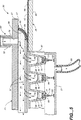
第3図は、第1図のポリマー合成用アレイ装置の、断面図で示された斜視側面図であり、該共通のチャンバーを介する、不活性ガス流の掃気作用を説明する図である。
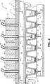
第4図は、第1図のポリマー合成用アレイ装置の、断面図で示された正面図であり、フレームアセンブリーに旋回可能に搭載されたヘッドアセンブリーを説明する図である。
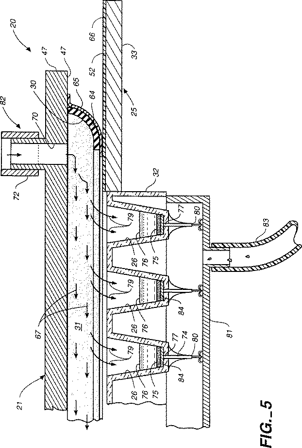
第5図は、実質的に第3図のライン5-5に沿ってとった、本発明のポリマー合成用アレイ装置の、断面図で示された拡大側面図であって、該液状試薬溶液と対応するフリットと、オリフィスとの間に形成される該毛管液体封止を示す図である。
第6図は、実質的に第3図のライン6-6に沿ってとった、本発明のポリマー合成用アレイ装置の断面図で示された、拡大側面図であり、気球封止ガスケットを示している。
第7図は、本発明のポリマー合成用アレイ装置の該ヘッドアセンブリーに搭載された放出アセンブリーの、拡大された模式的斜視平面図である。
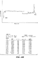
第8Aおよび8B図は、それぞれ実施例1で作成したオリゴヌクレオチドNo. 14および15の毛管電気泳動実験の結果を示す図である。
発明を実施するための最良の態様
以下本発明を幾つかの特定の態様に関連して説明するが、該説明は本発明を例示するものであり、本発明を何等限定するものではない。添付の請求の範囲に規定される本発明の真の精神並びに範囲を逸脱することなしに、当業者は、これらの好ましい態様に対して、本発明に関する種々の改良を施すことができる。より良く理解するために、種々の図面において、類似の部材は類似の参照番号で示されていることに注意すべきである。
まず、第1図および第2図を参照すると、そこには一般的に参照番号20で示されたポリマー合成装置が示され、これは液状試薬中で固体担体に連続的にポリマー構成単位を添加することにより、ポリマーを製造するための装置である。ところで、この装置20は配列の規定されたオリゴヌクレオチドを製造するのに特に適しているが、本発明は任意のポリマー鎖の合成のために利用できる。従って、用語「ポリマー構成単位」は、同一または種類を異にする他の部分と結合して、ポリマー鎖、例えばオリゴヌクレオチドおよびペプチド鎖を形成する、ある部分として定義されるであろう。
一態様において、該合成装置20は、簡単に言えば、一般的に21で示されるヘッドアセンブリーを含み、該アセンブリーは一般的に隔置された関係でこれに搭載された複数のノズル22(第2図)をもつ。各ノズル22は、これを通して制御放出を行うために、液状試薬24のタンク23(第7図)に接続されている。更に、一般的に25で示されたベースアセンブリーが含まれ、これは少なくとも一つの反応ウエル26および一般的に27で示された輸送機構(第3図)を有し、該機構はヘッドアセンブリー21およびベースアセンブリー25の少なくとも一方と連結されて、その間に相対的な運動を発生する。これによって、選択された一つの反応ウエル26および選択された一つのノズル22が、ポリマー鎖を合成するために、選択された1種の液状試薬24を該反応ウエルに投入するための整合状態に置かれる。一般的に30で示された滑動封止が、該ヘッドアセンブリーと該ベースアセンブリーとの間に配置されて、共通のチャンバー31(第3図)を形成し、該共通のチャンバーは該反応ウエルおよび該ノズル両者をその内部に収容する。
好ましい態様において、ウエル26のアレイ(第1図)はマイクロタイタープレート32中に形成されるように設けられ、該プレートはベースアセンブリー25の滑動プレート33によって担持される。この合成装置は、12本の等距離で隔置された行34として配列された96−ウエルのマイクロタイタープレート(表示の簡略化のために、全ウエルを図示してはいない)を使用するように、特別に設計されており、該列の各々は8本の等距離で隔置された列36の幅で、長いベースアセンブリー25の長手方向の軸35を横切って伸びている。マイクロタイタープレート32は、好ましくは化学的に不活性な材料、例えばポリプロピレンから作られる。勿論、任意の数のウエルまたは行列の配列が、本発明の真の精神および特徴を逸脱することなしに使用可能であると理解すべきである。
第1および2図は、更にヘッドアセンブリー21の搭載ブロック37に搭載されたノズル22が、更に該ウエルのアレイ26と同様に、ノズル行40列41のアレイとして配列されていることをも示している。好ましい態様においては、各々ヘッドアセンブリー21の長手方向の軸42と平行に伸びたノズル列41の数は、ウエル列36の数と等しい。従って、ノズルの特定のバンク即ち行40における各ノズルは、ウエル26のそれぞれの列36に対応しかつこれと整合されている。任意の1行40および列41における該ノズルも、該ウエルの行34と列36との間の間隔と同一の距離だけ等距離で隔置されており、これにより単一のサイクル中に、1以上のウエル行34と選択されたノズル行40との間の同時の整合が可能となる。即ち、ウエルのアレイを、同時の投入のために、複数の位置に沿ったノズルのアレイと整合させることができる。
この配列の規定されたオリゴヌクレオチド合成のためのアレイ技術は、最初にハイブリダイゼション配列決定のための高密度オリゴヌクレオチドアレイチップアセンブリーから発展したものであり、該技術は1991年9月4日付けで出願され現在継続中の米国特許出願第07/754,617号に記載されている。従って、このアレイ技術は、単独で、本発明の新規な特徴として特許請求されていない。しかしながら、該アセンブリーは、以下に説明されるであろうように、本発明の大規模生産性に対しては適しているとはいえない。
ポリマー鎖の構成並びに製造を単純化するために、ノズルアレイを介して該液状試薬を制御された様式で放出するための、該合成装置の放出アセンブリー43(第7図)は、特定のバンク即ち行40中の全ノズル22を、連絡可能に共通の独立した液状試薬タンク23に連結し、一方でノズルの各バンク即ち行40各々を、特定のポリマー合成に適用される異なる液状試薬と連結する。例えば、ノズル22の第一の行40は活性化剤テトラゾールのみを分配し、一方で該第二のノズル行はアミダイトチミジンを分配することができる。オリゴヌクレオチド合成において、液状試薬分配のこの順序は、アミダイトアデノシン、シトシン、およびグアニン、補助的塩基AnyN、洗浄/反応溶媒アセトニトリル、キャップ無水酢酸、キャップN-メチルイミダゾール、ヨウ素および脱保護剤ジクロロ酢酸またはトリクロロ酢酸の順で継続でき、これらの試薬全ては、規定された配列のオリゴヌクレオチドの合成に使用される試薬である。ところで、説明の簡略化のために、ノズルの僅かに5行のみが図示されている。更に、該アレイ中に含まれる任意のノズルを、任意の試薬タンクと連絡可能に結合できることが理解されよう。
本発明の放出アセンブリー43は、各ノズルバンクを、独立の分配チューブ44を介して共通の試薬タンク23に、連絡可能に結合する。各チューブは通路45(第6図)を含み、それぞれのノズルと結合された一端と、該タンク中に含まれる該液状試薬24中で終端している他端部を有する。これらのチューブは、搭載ブロック37およびヘッドアセンブリー21のヘッドプレート47を貫いて伸びた開口46に圧嵌めされている。好ましくは該試薬と接触した際の劣化に対してより高い抵抗性のテフロン(TEFLONR)製の各チューブ44の可撓性かつ半−弾性特性は、該チューブ外部とそれぞれの開口部との間の十分な封止を与える。
第2および6図に示したように、各チューブ44の遠方の端部はノズル22を形成し、該ノズルは、以前はそうでなかったが、横方向に配置されたスロット50内に延び、該スロットはヘッドプレート47の底部表面51内に形成される。従って、各独立したノズル22は、相対的滑動運動中に、ベース滑動プレート33の上部面52を妨害しないように嵌込まれている。更に、各ノズルのスロット50内への独立した延びは、該ノズルから試薬を放出した後に、該ノズル端部に蓄積された残留液状試薬の除去または棄却を促進する。
ノズル22を介する液状試薬の放出に関する重要な関心事が2つある。即ち、1)該ノズルの端部に液滴が懸垂状態で残留しないように、如何にしてすっかり液滴を排出するか、および2)該試薬の流れを該ウエルに放出する場合に、如何にして該反応チャンバーの内容物のはねを防止するかである。更に、該ノズルからの該試薬の射出速度は、該反応チャンバー中に放出された該第一および第二の試薬間の混合を誘発するのに十分である必要がある。非常に小さな液滴は、高い射出速度にて完全に射出できるが、該ウエル中に既に存在する液体の表面張力を凌駕して、混合を生ずるのに十分な運動エネルギーではない。これとは対照的に、大きな液滴も、高い射出速度の下で完全に放出されるが、隣接するウエルに対して該内容物を撥ね飛ばす傾向がある。低射出速度の下では、該試薬は該ノズル先端部から懸垂した最後の滴を残す傾向がある。これも該先端部断面積の関数である。その上、小さな毛管チューブを介する液体の流量は放出圧に正比例し、かつ該チューブの長さおよびその径に逆比例して変動する。放出圧およびノズルの形状並びに構成材料を開発する場合には、これら全ての変数を考慮すれば、該ノズル先端部から懸垂した液状試薬の残留滴を残すことなしに、完全に該試薬を追い出すことができる。従って、該液状試薬に依存して、これを連続流として、一連のパルスとしてあるいは液滴として分配することがより有利である可能性がある。
第7図に示したように、各試薬タンク23は、圧縮デバイス(図示せず)と接続された加圧チューブ53を含み、これはタンクの空気空間54を加圧して、貯蔵された該液状試薬を、該タンクから各分配チューブ44を通して流動させる。分配チューブ44を通しての試薬の放出は、該チューブに直列状に搭載された独立のバルブアセンブリー55のアレイによって調節される。これらのバルブアセンブリーは、ソレノイド駆動型の微小遮断バルブを備えることが好ましく、その各々は5μsec以内に開放および閉鎖の動作を行い、液状試薬の正確な容量を放出することができる。
各分配チューブ44を横切る一定の放出圧およびその結果としてのノズル22のバンクまたは行40内の任意のノズルを介する、液状試薬の一定の放出速度を確保するために、各分配チューブは独立に該試薬タンク中に含まれる該試薬中で終端するであろう。かくして、放出のために設定されたノズルの数とは独立に、この構成は、変動するライン圧力に起因する不均一な速度での放出をもたらさない。
本発明によれば、ベースアセンブリー25およびヘッドアセンブリー21は、該ベースアセンブリーとヘッドアセンブリーとの間の相対的運動を生じさせるための輸送機構27と協働して、該ウエルのアレイと複数位置におけるノズルのアレイとを整合させる。好ましくは、この輸送機構は、各行34のウエルが該ノズル列41との整合状態を維持するように、長手方向の軸35に沿って(第3図の仮想線)該ベースアセンブリーを移動させる。ベースアセンブリー25は、従って矢印60の方向に往復動させるためのフレームアセンブリー57(第3および4図)によって滑動可能に支持されている。マイクロタイタープレート32を担持する、滑動プレート33は、整合された運動を行うために、フレームアセンブリー57のトラック機構61内に滑動可能に受け取られる。従って、選択されたノズル(バルブアセンブリー55を介して)によっておよび該輸送機構の操作によって該試薬の放出を調節することにより、複数の均一な群の配列の規定されたポリマーを、迅速かつ再現性のある様式で、選択されたウエル中で同時に合成できる。
輸送機構27は、第3図に模式的に示したステップモーターアセンブリー62を含み、これは滑動プレート33と機能可能に連結されている。従って、ベースアセンブリー25はトラック機構61および直線状に増加する運動を行わせるための該ステップモーターと協働して、ウエルのアレイと、複数の位置におけるノズルのアレイとを整合させる。しかしながら、該輸送機構は、該ヘッドアセンブリーと相対的に該ベースアセンブリーを運動させる、任意のモーター/トラック構成により与えることができる。
ポリマーの合成を開始する前に、あるいは該合成工程が終了した後に、該ウエルのアレイを共通のチャンバー31の外側に配置し、該ウエル26を(ベースアセンブリー25の運動を通して)滑動封止30の右端または左端部まで移動させることによって、アクセスのために、外部環境に暴露することができる。従って、該ウエルアレイを、以下に論ずるように、清浄化し、もしくは固体担体材料を搭載することができる。更に、一旦該共通のチャンバーに収容された、該ウエルおよびノズルは、第4図に示したように、ヒンジアセンブリー63を通してアクセスでき、該ヒンジアセンブリーはヘッドアセンブリー21をフレームアセンブリー57に旋回可能に搭載する。
第1、3および5図を参照すると、本発明の該滑動封止が記載されている。ホスホルアミダイトカップリングによるオリゴヌクレオチド合成においては、2つの主な化学操作上の要求がある。というのは、該カップリング反応が迅速かつ不可逆的であるからであり、水および酸素は、両者共に合成中該共通の反応チャンバーから排除することが好ましい。ホスホルアミダイトは痕跡の水の存在によって加水分解に敏感となり、かつ空気との接触によって酸化に対して敏感となる。従って、滑動封止30は、ヘッドアセンブリー21の底部表面51と、ベースアセンブリー25の上部表面52との間に配置され、その周囲に、共通のチャンバー31中の該反応ウエルおよび該ノズル両者を含む。更に、以下に一層詳細に記載されるように、不活性ガスを共通のチャンバー31を通して流して、該チャンバーから痕跡の空気および水を排除することにより、加水分解および酸化を、排除されないとしても、最小化することができる。
滑動封止30は、周囲からの封止状態を維持し、一方で該ベースアセンブリーが該ヘッドアセンブリーに相対的に移動することを可能とするように形成される必要がある。好ましい態様においては、滑動封止30は、ヘッド底部表面51に搭載された上端とベース上面52と滑動可能に接触した他端または下端部64とを有する、弾性かつ矩形−形状のハイドロホイル(hydrofoil)または気球封止ガスケットによって与えられる。好ましくはゴム等により構成される、この特別なガスケットは、共通チャンバー内の圧力が増大した際に、ガスケット下端部64とベース上部面52との間の封止の一体性を増大する。第5図は、ガスケット下端部64が共通チャンバー31の内部に内方向に、周辺部がテーパーをもつように示されている。チャンバー内の圧が増大した場合に、ガスケット封止30の壁は外側に向かって膨張し、その結果該ガスケットの下端部と該ベース上面との間の接触表面積は増大して、これらの間を良好に封止、嵌合する。
滑動接触を容易にし、一方で周囲からの封止状態を維持するために、ガスケット封止30は、該ガスケットの下端部と該ベース上面との間に、好ましくはテフロン製の、粘着性の無い皮膜または層65(第5図)を含む。この層は、更に該封止ガスケットを残留液状試薬による表面吸着から保護する目的をも果たし、該残留液状試薬は、部分的にはその弾性特性のために、接触した場合に該ガスケットを劣化する傾向を示す。第5図に示したように、該ベースアセンブリーの上部面52も、テフロンの皮膜または層66を含んでいて、滑動接触を促進し、かつ該上部面を残留試薬から保護することができる。
ガスケットの下端部64とベース上部面52との間の封止は気密封止である必要がないことを理解するであろう。この封止ガスケットの主な機能は、該反応チャンバーから酸素を排除することにある。従って、通常合成中の全期間を通じて、共通チャンバー31内を、大気圧よりも僅かに大きくて、漏洩を生ずるはずの該ガス流が外方向に向かうような、最小の正の圧力を維持することが重要である。この最小の正の圧力差は、一般的に約1/100psi〜約1/10psiである。
前に示した如く、また第3、5および6図に見られるように、該チャンバーの反応上部空間から、痕跡の空気および水を、不活性ガス、好ましくはアルゴンによってフラッシングして、合成中の該アミダイトの加水分解および酸化を最小化することが望ましい。更に、該上部空間を介して、該不活性ガスを連続的に流して、反応性のアミダイトを、キャッピングおよび脱保護試薬、例えば水性ヨウ素蒸気またはトリクロロ酢酸から保護することも望ましい。該試薬は該アミダイトと反応するであろう。この保護は、ガス入口70から共通チャンバー31を通して不活性ガスの流れ(矢印67で示されている)を導入することにより達成され、該入口70はノズル22のアレイの上流側に位置し、また該不活性ガスは、該ノズルの下流側に位置するガス出口71を通して、該チャンバーを出ていく。ガス入口70は、入口管72(第1図)を通してガス源(図示せず)に接続され、該ガスは更に外部からの酸素の流入を阻止するために必要な正の圧力を、共通のチャンバー31に与える。該共通チャンバーの上部空間は比較的小さい(図では例示のために誇張されている)ので、該ノズルを通過した十分なガス流が、大容量のガスを消費することなく、該チャンバーを掃気しもしくはフラッシングするように工夫することができる。
該ガス入口は、ヘッドプレート47内に延びかつ該ヘッドプレート47の長手方向の軸42を横断して配列された、長い入口スロット70(第2図)によって与えられることが好ましい。この形状および配向は、上流部入口70から下流部入口71まで実質的に不活性ガスの層流を誘導し、これは該ノズルを横切る交叉流れを最小化し、かつ緩慢な試薬蒸気の不動領域を、該チャンバーから排除する。該ガス入口は、またヘッドプレート47を横切って延びた一群の開口によって与えられてもよく、しかもガス入口71は更に長いスロットまたは一群の開口によって与えられてもよいことに気づくであろう。
該チャンバーを介する該ガス流のために、酸および水分に敏感なホスホラミドは、該脱保護剤およびキャッピング剤の上流側に配置され、拡散ガスバリヤーを形成し、これは掃気効果を最大とする。従って、第3図に示すように、該ホスホラミドは、ガス入口70に近接したノズル22から分配され、一方キャッピング剤、洗浄剤および脱保護剤は、該ホスホラミド分配ノズルの下流側の、ガス入口71近傍に位置するノズルから分配される。
本発明のもう一つの局面においては、第5および6図に最もよく示されているように、ポリマー合成装置20は、反応ウエル26を備え、該ウエルは一般的に74で示され、該ウエル内に延びている少なくとも1個のオリフィスを有する。少なくとも一つの固体担体75が該ウエル内に配置され、その上でポリマー鎖を成長させかつこれを固定化している。ウエル26中の試薬溶液76は固体担体75および該固体担体に固定された少なくとも1種のポリマー構成単位と接触状態にある。オリフィス74は該共通チャンバー側からウエル26への入口77と、該ウエルから下部溜めます81への出口80を有する。重要なことは、該オリフィスが、そこに含まれる試薬溶液76に関して毛管液体封止を形成して、該試薬溶液を該ウエル内に保持し、その中でのポリマー鎖の成長を可能とするようなサイズおよび寸法をもつことである。更に溶液76をウエル26に維持するために、反応ウエル26中の該試薬溶液に及ぼされる共通チャンバーガス圧と、オリフィス出口80に及ぼされる第二のガス圧(第6図では、矢印79で示されている)との間の圧力差を、所定の値未満にする必要がある。最後に、圧力制御デバイス82が、該圧力差を、これが該所定の値を越えた場合に、該試薬溶液76をオリフィス74(第5図)を介して該ウエル26から排除するように調節するために設けられている。
簡単に言えば、選択されたウエル26’と選択されたノズル22’との間の適当な整合後に、該アレイ技術および上記の新規な装置を使用して、該液状試薬を選択されたウエル26’に投入できる。この投入された試薬溶液は、正確な寸法とされたオリフィス74を横切って集まり、比較的小さな圧力差(所定の値を越えない)との組み合わせで、オリフィス74を横切るメニスカスを形成して、該オリフィスを通して排出されることなく、該ウエル中に該溶液を保持するための毛管液体封止を生成する。この封止は、効果的に該共通反応チャンバーを、下部溜めます81の周囲から分離する。該合成反応を完了するのに十分な時間(一般的には、約1分)の経過後、該試薬溶液をオリフィス74を介してウエル26から下部溜めます81にパージする。これは、該ガス圧差を、該オリフィス内の毛管力を凌駕する、該所定の値を越えて増大させることによって達成される(第5図)。引き続き、このパージした試薬溶液を、排液出口83を介して、該溜めますから抜き出すことができる。この工程を各合成サイクル(即ち、脱保護、洗浄、カップリング、キャッピングおよび酸化段階)につき、所定の配列の規定されたポリマーが製造されるまで繰り返す。
一般的に84で示された保持デバイスが含まれ、これはウエル26の底部の、オリフィス74と該固体担体75との間に配置されており、該固体担体が該オリフィスを通り抜けるのを実質的に阻止するように形成され、かつそのような寸法が与えられている。保持デバイス84は、好ましくはポリエチレンまたはガラス繊維フリットで与えられ、該試薬溶液の通過を可能とし、一方で該固体担体および該ウエル内の該担体上で成長するポリマー鎖を保持する、フィルタ膜として機能する。従って、該フリットの多孔度も、該毛管液体封止の形成および該反応ウエルをパージするのに必要な該圧力差を決定する際のファクタとなる。
共通チャンバー31と下部溜めます81との間の圧力差を調節し、かつ制御するために、上記の如く、これらの間に圧力調節デバイス82が機能可能に接続されている。好ましい態様において、圧力調節デバイス82は、共通チャンバー31のヘッドスペースから試薬毒物をフラッシングするのに使用される、ガス流動アセンブリーと一体化されている。該不活性ガスが、ガス入口70からガス出口71まで、該チャンバーを自由に掃気する際に、最小の圧力差は、一般に約1/100psi〜約1/10psiの範囲に維持される。この圧力差は、周囲空気の該共通のチャンバー内への漏洩を防止するのに十分に正の値であり、かつ各ウエル内の該毛管液体封止の毛管力を凌駕するには不十分である。不活性ガスのガス出口71を介する流出を阻止または制限することにより、チャンバー31内部の圧力を高め、これにより該溜めますの圧が同一のまたはより高い速度で増大しない場合には、該ウエルをパージ(第5図)するための該圧力差を高めることができる。
従って、該圧力調節デバイス82は、ガス出口71と接続したチャンバーバルブ85(第1図)を含み、これは共通チャンバー31を掃気する不活性ガスの流出を制御する。従って、チャンバーバルブ85を介する流れを十分に遮りもしくは制限することにより、該差圧を該所定の値以上に上げて、同時に該ウエルの試薬溶液をパージすることができる。同様に、チャンバーバルブ85を十分に開放することにより、該投入された溶液を該選択されたウエル中に維持したい場合には、該差圧を該所定の値以下に下げることができる。
該ウエル中に十分な液体ヘッドが存在するか、あるいは該共通チャンバーと該下部の溜めますとの間が、該オリフィス中の該毛管力を越えるのに十分なガス圧差となるまで、該液状反応溶液はウエルオリフィス74から漏洩またはパージされないであろう。該オリフィスからの重力によりおよび圧力により誘発される漏れの割合は、主として溶媒の粘性、該フリットの多孔度、該オリフィスのサイズ、および該ガス圧力差によって支配される。例えば、10μUHMWポリエチレンフリットおよび0.015in2オリフィスは、該オリフィス中の該毛管力を越える前に、少なくとも0.79inのアセトニトリル(粘度約0.345cps(操作温度約約68°Fにおいて7.2×10⁻⁵(1bf・s)/ft2)を有する)ヘッドを維持するであろう。他方、該圧力差を該所定の値(一般に約1psi)を越えて、約5psiまで増大することにより、該ウエルのパージは迅速に起こるであろう。実際に、約2.5psi〜約5psiの範囲内の圧力差を維持して、試薬溶液と同時に該反応ウエルを十分にパージすることが必要である。個々のウエルが空になるにつれて、該マイクロタイタープレートの空となったウエルを介する不活性ガスの流量は実質的に増大し、共通チャンバー31内の圧を低下する。従って、この内圧の低下は、更に該オリフィスを通る該試薬溶液のパージまたは排液速度を減ずる。これはフィルタ膜84を保持することにより大きくなる。
この圧力差は、また該反応ウエルをパージするために、下部溜めます81内を真空にすることによっても発生することが理解されよう。第1図は、下部溜めます81へのアクセス開口86がカバー87によって封止でき、かつ排液出口83が、該溜めます内に真空を発生する真空ポンプと接続可能であることを示している。該圧力差は、共通チャンバー31内の正の圧力と溜めます81内の真空との組み合わせによっても生成される可能性がある。更に、該試薬溶液は該チャンバーを連続的に流動するというよりも、その反応のために該反応ウエル中に集められるので、幾つかの他の公知技術のアセンブリーで使用されているように、試薬の消費は実質的に最小化され、従って経費の節減が図られる。労働コストも各サイクル時間を最小化することにより下げられる。
全ての同時に行われる機能を調和させるために、制御機構90(第7図)が、輸送機構27、バルブアセンブリー55および圧力調節デバイス82の間に動作可能に接続されている。配列ファイルを入力でき、該配列ファイルはウエル位置、規模、最終的な脱保護指令および各オリゴヌクレオチドに対するATGCおよびN(異常塩基)配列に関する順序立ったリストを含む。この配列ファイルはコマンドファイルと協働し、該コマンドファイルは、脱保護/洗浄/カップリング/キャッピング/酸化工程の実際の数および順序、並びに完全なカップリングサイクルを規定する、待機および加圧および/または真空排気段階の期間の長さを示すのに使用される。
オリゴヌクレオチドは、典型的には3'−サクシネート結合により調節された多孔度をもつガラス(CPG)に前もって結合された第一のヌクレオチドを有する該CPG製の固体担体上で合成される。従って、ポリマー合成の準備の際に、各ウエルには正確なCPG誘導体が独立に担持される。プレート全体の合成を、ただ一つのCPG誘導体、例えばT(即ち、dT-Icaa-CPG)を使用して開始することができるが、あらゆる塩基が該第一の位置に存在し得るアレイ合成を実施することがより望ましい。しかしながら、各ウエルに適当に乾燥したCPG誘導体0.5mgを計り取ることは面倒かつ時間浪費である可能性がある。
本発明では、平衡化密度スラリー法(balanced density slurry technique)を利用して、正確な量のCPGを反応ウエルに投入する。懸濁溶液中に該CPGを懸濁することにより、自動的にまたは手動で、ピペットで対応する体積の懸濁溶液を計り取ることによって、所定量のCPGをウエル内に正確に投入できる。例えば、CPGの沈殿していない10%-1%w/v懸濁液を、2.5/1 v/vのジブロモメタン−ジクロロメタン溶液中で調製できる。引き続き、上記の方法を利用した合成の前に、該CPGを洗浄し、懸濁溶液のパージを行うことができる。
本発明のもう一つの局面においては、ポリマー鎖の合成法が提供され、該方法は以下の諸工程:A)反応ウエル26と、合成装置20の選択された一つのノズル22とを、ヘッドアセンブリー21およびベースアセンブリー25の少なくとも一方に連結された輸送機構27を通して整合させて、これらの間に相対的な運動を発生させる工程、およびB)液状試薬24を、該一つのノズルを介して、試薬タンク23からウエル26を投入して、ポリマー鎖の合成を可能とする工程を含む。最後に、C)該試薬から放出される有害な煙霧を、共通チャンバー31の入口70に連結され、かつ該ノズルの上流側に位置する加圧ガス源からのガス流路を介して、共通のチャンバー31から、該ノズルの下流側に位置する該共通のチャンバーの出口71を介して、該チャンバーから掃気する。
ポリマー合成のもう一つの方法が、ポリマー構成単位を、液状試薬中で、ポリマー鎖を成長させかつ固定するための少なくとも一つの固体担体に連続的に添加することにより、ポリマー鎖を製造するために提供される。この方法は、A)液状試薬24を、適当なサイズのオリフィス74をもつ反応ウエル26に、少なくとも一つの固体担体75および該固体担体75に固定された該ポリマー鎖の少なくとも1種のポリマー構成単位と接触状態で投入する工程と、ウエル26内の該試薬溶液を保持するための毛管液体封止を形成して、固体担体75上でのポリマー鎖の成長を可能とする工程を含む。この方法の次の工程は、B)反応ウエルチャンバー31に第一のガス圧を、該第一のガス圧とオリフィス74の出口80に及ぼされる第二のガス圧との間の差圧が、該毛管液体封止を凌駕し、かつオリフィス74を通してウエル26からの該試薬溶液を追い出すのに必要な所定の値を越えるように印加することを含む。
上記2つの方法の諸工程を繰り返すことにより、一本のポリマー構成単位の連続した連鎖を形成することができる。
以下の実施例は上記本発明の利用法をより十分に説明するのに役立ち、また本発明の様々な局面を実施するための最良の態様を示すためのものである。この実施例は本発明の真の範囲を何等限定するものではなく、寧ろ本発明を例示する目的で与えられるものである。オリゴヌクレオチド合成のあらゆる方法が本発明において利用可能であるものと理解すべきである。
実施例1:15個のオリゴヌクレオチドのアレイの合成
一般的合成手順はオリゴヌクレオチド合成のホスホラミダイトおよびハイドロジェンホスホネート法に従う。例えば、オリゴヌクレオチドおよびアナログズ(Oligonucleotides and Analogues): アプラクティカルアプローチ(A Practical Approach), F. エクシュタイン(Eckstein)編,IRLプレス,オックスフォードユニバーシティー; オリゴヌクレオチドシンセシス(Oligonucleotide Synthesis): アプラクティカルアプローチ(A Practical Approach),ゲイト(Gait)編,IRLプレス,ワシントンD.C.; および米国特許第4,458,066号、同第4,500,707号および同第5,047,524号に概説された方法に従う。これら全てを本発明の参考とする。本発明においては、他のオリゴヌクレオチド合成法も利用できるものと理解すべきである。
一般的に、該合成反応の基本的工程は以下の通りであり、これらを適当なアセトニトリル洗浄工程と組み合わせる。
a) 5'位置において保護されている第一のヌクレオチドを、固体担体(通常は調節された多孔度をもつガラス(CPG)との誘導体とするか、あるいは予備誘導体化によって得る。
b) 該第一のヌクレオチドの糖残基を、トリクロロアセティック−メチレンクロリド酸を使用して、脱保護または脱トリチル化する。これは着色生成物を与え、該生成物により反応進行を追跡できる。
c) 保護された燐、糖および塩基の残基をもつ第二のヌクレオチドを、通常テトラゾール触媒の存在下で、該成長中の鎖に添加する。
d) 未反応の第一のヌクレオチドを、無水酢酸およびN-メチルイミダゾールを使用してキャッピングして、永続的誤差を回避する。
e) 該ホスファイトトリエステルを、ヨウ素試薬を使用して酸化して、より安定なホスフェートトリエステルを形成する。
f) 該オリゴヌクレオチドの所定の長さに応じて必要とされるだけ、この方法を繰り返す。
g) 通常は高温にてアンモニア水を使用して、該固体担体の開裂を時間単位の期間に渡り実施する。
かくして、配列ファイルが作成された。これは合成すべき各オリゴヌクレオチドの3'-5'配列およびウエル数、各ヌクレオチドに対する反応の規模、および該反応の終了時点において、該生成物につき最終的な脱トリチル化を実施すべきか否かを示している。このソフトウエアは、独立した、異なる長さのオリゴヌクレオチドおよび異なる規模のその合成を同時に実施するように設計されていた。この15個の異なるオリゴヌクレオチドの配列を以下の第1表に示した。
各ウエルに、誘導されたA、T、CまたはGの何れかの第一塩基を有する、正確な量のCPGを添加した。例えば、0.5mgのCPGを20ナノモル規模の反応で使用した。該CPGビーズを、ジブロモメタン−クロロホルム中に分散されたスラリーとして、ピペットにより各ウエルに添加した。この段階は、該プレートを該装置に取り付ける前に、通常の実験室の雰囲気下で実施した。該プレートを該装置に取り付けた後に、WASHアセトニトリルサイクルを実施して、該スラリーを洗浄しかつ全てのウエルが適当に排液されていることを確認した。
該ノズルバルブタンクを、アルゴンでフラッシングし、次いで空気および水の混入を防止すべく加圧輸送により、供給ボトルからの新鮮な試薬で満たした。このバルブタンクを、次に該コンフィギュレーション圧(4psi)まで加圧した。次いで、各試薬に対してパージ位置にある該滑動プレートにより、少量の液体を分配することにより、ノズルチューブを充填した。
試薬添加および反応の待機期間中は、該反応チャンバーを横切る層状の掃気ガス流を、0.4l/分に調節したが、この際の内部圧力は約0.02psiであった。使用済試薬の除去および洗浄サイクル中に、該チャンバー内の圧力は最大5psiまで増大した。2.5psiにおいて、該合成ウエルを約150λ/秒の速度で排液した。
次いで、この装置をオートマチック(AUTOmatic)モードに切り換えて、実際の合成を開始した。該装置を該第一、第二および最終サイクル中に停止して、比色分析のために、該DEBLOCKトリチル生成物の採取を可能とした。これは、下部真空/排液チャンバー内の第二の96−ウエルのマイクロタイタープレートを、該合成プレートの毛管出口先端部直下にずらすことにより実施した。490nmにおける脱トリチル化溶液の光学密度を、プレートリーダーを使用して読み取った。この第一のサイクルに対する値はウエル中に入れられたCPGの量を裏付け、また該第二のサイクルと該最終のサイクルとの比較は、該合成カップリング効率の算出を可能とした。該最終サイクルの値は、またアンモニア開裂により側鎖の脱保護後に得られるであろうオリゴヌクレオチドの量をも示した。
該装置が全てのウエルにおいて該合成を完了した後、該合成プレートを該装置から取り出した。該合成プレートを第二の96ウエル脱保護プレート(ベックマンディープウエルタイタープレート(Beckman deep-well titer plate)267001)の上に重ねた。各ウエルに200μlの濃厚NH4OHをピペットで分配することによって、これらのオリゴヌクレオチドを該担体から開裂し、次いで25℃にて15分間インキュベートした。これらのアンモニア開裂溶液を該フィルタおよび毛管出口を通して、該脱保護プレートの該ウエルに溶出したが、この際に該積層体を加圧し、真空を印加し、あるいは簡単な遠心処理にかけた。この開裂段階を、新たなアンモニアのアリコートを用いて2度繰り返した。
合成に使用した該ホスホラミダイトがベンジルおよびイソブチリル保護基を有する場合には、この最終の脱保護段階は、該粗製アンモニア開裂生成物を加熱することにより完了させた。該脱保護タイタープレートのウエルを、窪みをもつシリコンゴムキャップ(ベックマン(Beckman)267002)で封止し、該キャップをバネ式プレートプレスを使用して所定位置に維持した。この封止した装置をエアーオーブンまたは水浴中で、55℃にて8-15時間加熱し、次いで氷浴中で冷却した。該脱保護プレートを該プレスから取り出し、手短に遠心処理した後、該キャップを取り外した。
次に、該アンモニア溶液を、マイクロプレートローターを備えたサバント210スピードバク(Savant 210 Speed Vac)を使用して、蒸発乾固した。かくして得られたオリゴヌクレオチドペレットは、多くの配列決定用プライマーとしておよびPCR用途において直接使用するのに十分に純粋であった。最後のトリチルアッセイにより予想されたオリゴヌクレオチドの量は、260nmにおける光学密度により立証され、また該生成物の均一性はHPLCまたは毛管ゲル電気泳動法によってアッセイした。毛管電気泳動分析は、アプライドバイオシステムズ(Applied Biosystems)270A装置を製造業者のプロトコールに従って実施した。上記実験で得たオリゴヌクレオチド14および15に対する結果をそれぞれ第8Aおよび8B図に示した。20−マーの20ナノモル規模での合成についての典型的な収量は2.5OD(85μg)であった。 Technical field
The present invention relates generally to polymer synthesizers, and more particularly to polymer synthesizers using arrays.
Background art
More recently, oligonucleotides are playing an increasingly increasing and more important role in diagnostic medicine, forensic medicine and molecular biological research. One major function of these polymers is their use in gene probe assays, particularly for detecting specific nucleic acid sequences.
Gene probe assays are utilized for a variety of purposes including genetic consultation, histocompatibility testing and molecular biological studies. For example, an individual can be tested to see if the individual carries a gene associated with Huntington's disease or cystic fibrosis. Another use of gene probe assays involves determining suitability prior to tissue transplantation and matching tissue or blood samples for forensic purposes. Finally, in molecular biology studies, these assays are used to explore the homology of genes from various species, and only a portion of the nucleic acid or amino acid sequence, eg, in the polymerase chain reaction (pcr). It is widely used for the cloning of known genes.
Typically, these types of assays test for the presence of specific nucleic acid sequences, usually DNA sequences, although RNA sequences can be utilized as well. As is well known in the art, this is accomplished using oligonucleotides synthesized to have a specific predetermined sequence. The sequence of an oligonucleotide probe can be a “putative” probe based on a known amino acid sequence, a known DNA sequence, or based on homology with a known or putative DNA or amino acid sequence. Since DNA is a “degenerate” code and several DNA sequences result in a single amino acid sequence, gene probe assays based on amino acid sequences often utilize a pool of related oligonucleotides, each of which is an oligonucleotide. Have different specific sequences. Thus, although related in many ways, it is often necessary to generate separate oligonucleotides to clone a single gene.
In addition to the actual sequence, there are many parameters that can be varied in the synthesis of the oligonucleotide. Also, it is often necessary to synthesize these polymers in various lengths because, in general, the longer the oligonucleotide probe, the more specific the gene probe assay, Specificity may or may not be desirable in any particular application. Oligonucleotides can be made from deoxyribonucleotides or ribonucleotides or mixtures thereof. In addition, oligonucleotides with denatured or non-standard bases or with incorporated non-radioactive labels may be desirable. Similarly, for some applications it is possible to produce oligonucleotides with altered ribose-phosphate backbones.
In addition to the gene probe assay, there are several other uses for oligonucleotides. For example, the formation of single stranded oligonucleotides with specific sequences can be used in forming extremely stable triplex DNA structures. Other uses include the direct construction of synthetic genes and plasmid vectors by linking or conjugating with
Accordingly, as the utilization of synthetic oligonucleotides increases, so does their demand. Accordingly, this has led to the development of a novel synthesizer of oligonucleotides with a defined sequence and a methodology for the basic procedure of the synthesis. However, the use of these devices and methods is generally expensive and is not easy to use for mass production. Typically, current generation automated DNA sequence synthesizers place derivatized solid supports, such as controlled pore glass (CPG), in individual reaction chambers of a column. A stable mooring part is provided and solid phase synthesis is started on it. Using a series of complex valve systems and a pump coupled to the column, appropriately selected reagents are sequentially filtered through the chamber in a predetermined manner. Contact of the reagent with the polymer unit pre-fixed to the CPG, held and supported in the chamber by a porous frit for sample support, causes a reaction and results in continuous growth there. .
While each column of this assembly is effective to rapidly mass produce a set of uniform sequence defined oligonucleotides, this conventional assembly only provides the availability of four columns. . The increase in column capacity is limited by the physical limitations of the valve system configuration. As a result, only four independent synthesis cycles can be performed simultaneously. In addition, the synthesizer is generally not suitable for automation in combination with other laboratory robotic equipment, so the operator manually intervenes to attach and remove each separate synthesis column. There is a need. Such handling increases human error.
A more important limitation is that all reagents are pumped through a common manifold passage. Accordingly, only one reagent or a combination thereof can be loaded into the selected column at the same time. For example, the reagent “tetrazole” cannot be charged to column 1 while a specific amidite reagent cannot be simultaneously charged to column 4. In addition, for each independent synthesis or reaction, the common manifold passage and the valve system coupled thereto may be flushed with a detergent to remove residual amidite or deprotection reagent in the wrong column. It is necessary not to be thrown in. This method is time consuming and increases operating costs.
The synthesis of bound oligonucleotide or peptide arrays is also generally known in the art. In one method of parallel synthesis, also known as tea bag or disk design, an individual packet or disk array of solid carrier beads is processed for processing by a selected amidite. Physically split into 4 amidite subsets. After processing each packet of beads with the common reagent, the packet needs to be manually divided again into four subsets for later synthesis cycles. Such splitting and subdivision is extremely cumbersome and results in increased effort to prepare a large array of oligonucleotides.
Another method using an array is the pin dipping method for the parallel oligonucleotide synthesis method. Geysen, J. Org. Chem., 1991,56, p. 6659. In this method, a small amount of solid support is fused into an array of solenoid-type regulated polypropylene pins that are later immersed in a tray containing the appropriate reagents. However, the density of the array is limited and the dipping procedure used is cumbersome to implement.
Yet another method of oligonucleotide array synthesis is disclosed in Southern, Genome Mapping Sequence Conference, May 1991, Cold Spring Harbour, NY. In the method, selected areas of the glass plate are physically concealed and a predetermined chemical reaction is performed on the unoccluded portion of the glass plate. The problem associated with this method is that after each interaction, the previous mask must be removed and a new mask applied. Ford et al., Science, 1991,251, p. 767 describe another method for synthesizing very high density 50μ arrays of peptides (and possibly oligonucleotides) using mask-induced photochemical deprotection and synthesis intermediates. ing. This method is limited by the low rate of photochemical deprotection and the susceptibility of side reactions in oligonucleotide synthesis (eg, thymidine dimer formation). Khrapko et al., FEBS Letters, 1989,256, p. 118 suggests a simplified synthesis and immobilization of a large number of oligonucleotides by direct synthesis on a two-dimensional support, where each of the four nucleotides is assigned to a given dot on the matrix. It uses a printer-like device that allows it to be collected inside. However, no details are given on how to make and use such devices.
In general, the related art generally includes a number of ingenuity and information regarding the synthesis of oligonucleotide or peptide arrays to determine the nucleotide sequence or amino acid sequence of a specific binding peptide. However, existing or suggested methods are limited and do not advantageously and reliably mass produce very large arrays that are required for effective large-scale sequencing.
Disclosure of the invention
Accordingly, one object of the present invention is to provide a polymer synthesizer and method for constructing sequence-defined polymer chains.
Another object of the present invention is to provide a polymer synthesizer and method for reproducibly and rapidly preparing large quantities of oligonucleotide or peptide arrays.
Yet another object of the present invention is to provide an apparatus and method for polymer synthesis that reduces the waste of reagents when preparing an array of oligonucleotides in large quantities.
It is yet another object of the present invention to provide a polymer synthesis apparatus and method for preparing large quantities of oligonucleotide arrays at a reduced cost.
Another object of the present invention is a polymer array that is durable, dense, easy to maintain, contains a minimum number of components, is easy to use by unskilled personnel, and can be economically manufactured. It is to provide a synthesis apparatus and method.
According to the above object, one embodiment of the present invention provides a polymer synthesizer for producing a polymer chain by continuously adding a polymer constituent unit to a reagent solution. The synthesizer generally includes a head assembly having a plurality of nozzles mounted in a spaced relationship. Each nozzle is coupled to a tank of liquid reagent for discharge in a controlled manner through it. And a base assembly having at least one reaction well and a transport mechanism coupled to at least one of the head assembly and the base assembly for creating relative motion therebetween. . As a result, the reaction well and one selected nozzle are arranged in an aligned state in which a liquid reagent is introduced into the reaction well for the synthesis of a polymer chain. A sliding seal is provided between the head assembly and the base assembly to form a common chamber that houses both the reaction well and the nozzle.
The synthesizer can further include an inlet leading to the common chamber disposed upstream of the nozzle and an outlet from the common chamber disposed downstream of the nozzle. A source of pressurized gas is connected to the inlet and continuously flows gas from the upstream side to the downstream side through the common chamber to the outlet to remove harmful fumes emitted from the reagent. And maintain a diffused state of air and moisture.
In another aspect of the invention, a polymer synthesizer is provided that includes a base assembly having a reaction well and at least one orifice extending into the well. At least one solid support is placed in the well for growing polymer chains thereon and immobilizing it. The reagent solution in the well is in contact with the solid support and at least one polymer constituent unit of the polymer chain immobilized on the solid support. Further included is a retention device disposed within the well, which is formed and dimensioned to substantially prevent the solid support from passing through the orifice. The orifice has an inlet to the well and an outlet from the well, yet forms a capillary liquid seal to maintain the reagent solution in the well and to allow polymer chains to grow therein It has dimensions. In order to maintain the solution in the well, the differential pressure between the first gas pressure exerted on the reaction well and the second gas pressure exerted on the orifice outlet was predetermined. Must be less than the value. Finally, a pressure adjustment device is provided to control the differential pressure such that if it exceeds the predetermined value, the reagent solution is expelled from the well through the orifice.
The present invention also includes a method of synthesizing a polymer chain in a synthesizer, which includes the following steps: A) the reaction well and a selected nozzle, the head assembly and the base. Aligning through a transport mechanism coupled to at least one of the assemblies to generate relative movement therebetween; and B) liquid reagent from the reagent tank through the one nozzle to the well. And the step of allowing the synthesis of the polymer chain. Finally, C) harmful common fumes released from the reagent are connected to the inlet of the chamber and via a gas flow path from a pressurized gas source located upstream of the nozzle, the common chamber To the outlet of the common chamber located downstream of the nozzle.
Another method of polymer synthesis is to produce polymer chains by continuously adding polymer building blocks to at least one solid support in a liquid reagent for growing and fixing polymer chains. Provided. In this method, A) liquid reagent is brought into contact with at least one solid support and at least one polymer constituent unit of the polymer chain fixed to the solid support in the reaction well having an orifice of an appropriate size. Loading and forming a capillary liquid seal to hold the reagent solution in the well to allow polymer chain growth on the solid support. The next step of the method consists of B) applying a first gas pressure to the reaction well and a differential pressure between the first gas pressure and a second gas pressure exerted on the outlet of the orifice. Applying beyond the liquid seal and exceeding a predetermined value necessary to expel the reagent solution from the well through the orifice.
[Brief description of the drawings]
The assembly of the present invention will be more readily understood when the following description of the best mode for carrying out the invention and the appended claims are considered in conjunction with the accompanying drawings, Other features as well as advantages. here,
FIG. 1 is an exploded perspective plan view of an array device for polymer synthesis assembled according to the present invention.
FIG. 2 is a perspective bottom view showing the head assembly of the polymer synthesizing array device of FIG. 1, showing the fitted nozzle end.
FIG. 3 is a perspective side view of the polymer synthesizing array apparatus of FIG. 1 shown in a sectional view, and is a view for explaining the scavenging action of an inert gas flow through the common chamber.
FIG. 4 is a front view of the polymer synthesizing array apparatus of FIG. 1 shown in a sectional view, and is a view for explaining a head assembly that is pivotably mounted on a frame assembly.
FIG. 5 is an enlarged side view of the polymer synthesis array device of the present invention taken substantially along line 5-5 of FIG. FIG. 5 shows the capillary liquid seal formed between a corresponding frit and an orifice.
FIG. 6 is an enlarged side view, taken along line 6-6 of FIG. 3 and shown in cross-section of the polymer synthesis array device of the present invention, showing a balloon sealing gasket. ing.
FIG. 7 is an enlarged schematic perspective plan view of a discharge assembly mounted on the head assembly of the polymer synthesis array device of the present invention.
FIGS. 8A and 8B are diagrams showing the results of capillary electrophoresis experiments of oligonucleotides No. 14 and 15 prepared in Example 1, respectively.
Best Mode for Carrying Out the Invention
The present invention will now be described in connection with certain specific embodiments, but the description is illustrative of the invention and is not intended to limit the invention in any way. Without departing from the true spirit and scope of the present invention as defined in the appended claims, those skilled in the art can make various improvements to the present invention to these preferred embodiments. For better understanding, it should be noted that in the various drawings, like elements are designated with like reference numerals.
Referring first to FIGS. 1 and 2, there is shown a polymer synthesizer, generally designated by
In one embodiment, the
In a preferred embodiment, an array of wells 26 (FIG. 1) is provided to be formed in a
FIGS. 1 and 2 also show that the
The array technology for defined oligonucleotide synthesis of this sequence was first developed from a high-density oligonucleotide array chip assembly for hybridization sequencing, which was published in September 1991 4 No. 07 / 754,617 filed on the date and currently pending. Therefore, this array technology alone is not claimed as a novel feature of the present invention. However, the assembly is not suitable for the large scale productivity of the present invention, as will be explained below.
In order to simplify the construction and production of polymer chains, the synthesizer release assembly 43 (FIG. 7) for releasing the liquid reagent in a controlled manner through a nozzle array is a specific bank or All
The
As shown in FIGS. 2 and 6, the distal end of each
There are two important concerns regarding the release of the liquid reagent through the
As shown in FIG. 7, each
In order to ensure a constant discharge pressure across each
In accordance with the present invention, the
The
Before starting the synthesis of the polymer or after the synthesis process is finished, the array of wells is placed outside the
Referring to FIGS. 1, 3 and 5, the sliding seal of the present invention is described. In oligonucleotide synthesis by phosphoramidite coupling, there are two main chemical operational requirements. This is because the coupling reaction is rapid and irreversible, and both water and oxygen are preferably excluded from the common reaction chamber during synthesis. Phosphoramidites are sensitive to hydrolysis due to the presence of trace water and sensitive to oxidation by contact with air. Thus, the sliding
The sliding
In order to facilitate sliding contact, while maintaining a sealed condition from the surroundings, the
It will be appreciated that the seal between the gasket
As indicated previously and as seen in FIGS. 3, 5 and 6, trace air and water are flushed from the reaction headspace of the chamber with an inert gas, preferably argon, during synthesis. It is desirable to minimize hydrolysis and oxidation of the amidite. It is further desirable to continuously flow the inert gas through the headspace to protect reactive amidites from capping and deprotecting reagents such as aqueous iodine vapor or trichloroacetic acid. The reagent will react with the amidite. This protection is achieved by introducing a flow of inert gas (shown by arrow 67) from the
The gas inlet is preferably provided by a long inlet slot 70 (FIG. 2) that extends into the
Due to the gas flow through the chamber, acid and moisture sensitive phosphoramides are placed upstream of the deprotecting and capping agents to form a diffusion gas barrier, which maximizes the scavenging effect. Thus, as shown in FIG. 3, the phosphoramide is dispensed from the
In another aspect of the invention, as best shown in FIGS. 5 and 6, the
Briefly, after appropriate alignment between the selected well 26 ′ and the selected
A holding device, generally designated 84, is included, which is located at the bottom of the well 26, between the
In order to regulate and control the pressure difference between the
Thus, the
The liquid reaction until there is sufficient liquid head in the well or there is a sufficient gas pressure difference between the common chamber and the lower reservoir to exceed the capillary force in the orifice. The solution will not leak or be purged from the
It will be appreciated that this pressure differential can also be generated by evacuating the
A control mechanism 90 (FIG. 7) is operatively connected between the
Oligonucleotides are typically synthesized on a solid support made of CPG having a first nucleotide pre-bound to a glass (CPG) with a porosity controlled by a 3'-succinate linkage. Therefore, the correct CPG derivative is independently carried in each well during preparation for polymer synthesis. Whole plate synthesis can be initiated using only one CPG derivative, eg T (ie, dT-Icaa-CPG), but an array synthesis is performed where any base can be in the first position It is more desirable to do. However, measuring 0.5 mg of a suitably dried CPG derivative in each well can be cumbersome and time consuming.
In the present invention, an accurate amount of CPG is introduced into the reaction well using a balanced density slurry technique. By suspending the CPG in the suspension solution, a predetermined amount of CPG can be accurately put into the well by pipetting the corresponding volume of suspension solution automatically or manually. For example, a non-precipitated 10% -1% w / v suspension of CPG can be prepared in a 2.5 / 1 v / v dibromomethane-dichloromethane solution. Subsequently, the CPG can be washed and the suspension solution purged prior to synthesis using the above method.
In another aspect of the present invention, a method for synthesizing a polymer chain is provided, which comprises the following steps: A) a reaction well 26 and a selected
Another method of polymer synthesis is to produce polymer chains by continuously adding polymer building blocks in a liquid reagent to at least one solid support for growing and fixing the polymer chains. Provided. In this method, A) a
By repeating the steps of the above two methods, a continuous chain of one polymer structural unit can be formed.
The following examples serve to more fully illustrate the use of the present invention described above and are intended to illustrate the best mode for carrying out various aspects of the present invention. This example does not limit the true scope of the invention in any way, but rather is given for the purpose of illustrating the invention. It should be understood that any method of oligonucleotide synthesis can be used in the present invention.
Example 1: Synthesis of an array of 15 oligonucleotides
The general synthetic procedure follows the phosphoramidite and hydrogen phosphonate method of oligonucleotide synthesis. For example, Oligonucleotides and Analogues: A Practical Approach, F. Eckstein, IRL Press, Oxford University; Oligonucleotide Synthesis: Apractical Follow the methods outlined in A Practical Approach, edited by Gait, IRL Press, Washington, DC; and US Pat. Nos. 4,458,066, 4,500,707, and 5,047,524. All of these are referenced for the present invention. It should be understood that other oligonucleotide synthesis methods may be utilized in the present invention.
In general, the basic steps of the synthesis reaction are as follows, which are combined with a suitable acetonitrile washing step.
a) The first nucleotide protected at the 5 ′ position is derivatized with a solid support (usually glass (CPG) with controlled porosity) or obtained by pre-derivatization.
b) The sugar residue of the first nucleotide is deprotected or detritylated using trichloroacetic-methylene chloride acid. This gives a colored product which can be followed by the progress of the reaction.
c) A second nucleotide with protected phosphorus, sugar and base residues is added to the growing chain, usually in the presence of a tetrazole catalyst.
d) Capping the unreacted first nucleotide using acetic anhydride and N-methylimidazole to avoid permanent errors.
e) The phosphite triester is oxidized using an iodine reagent to form a more stable phosphate triester.
f) Repeat this method as needed for the given length of the oligonucleotide.
g) Cleavage of the solid support is carried out over a period of time, usually using aqueous ammonia at an elevated temperature.
Thus, a sequence file was created. This is the 3'-5 'sequence and number of wells for each oligonucleotide to be synthesized, the magnitude of the reaction for each nucleotide, and whether the product should be subjected to final detritylation at the end of the reaction. Is shown. This software was designed to simultaneously perform independent, different length oligonucleotides and different scales of their synthesis. The sequences of these 15 different oligonucleotides are shown in Table 1 below.
To each well was added the correct amount of CPG with any derived A, T, C or G first base. For example, 0.5 mg of CPG was used in a 20 nanomolar scale reaction. The CPG beads were added to each well by pipette as a slurry dispersed in dibromomethane-chloroform. This step was performed in a normal laboratory atmosphere before attaching the plate to the apparatus. After attaching the plate to the apparatus, a WASH acetonitrile cycle was performed to wash the slurry and to ensure that all wells were drained properly.
The nozzle valve tank was flushed with argon and then filled with fresh reagent from the supply bottle by pressurized transport to prevent air and water contamination. The valve tank was then pressurized to the configuration pressure (4 psi). The nozzle tube was then filled by dispensing a small amount of liquid with the sliding plate in the purge position for each reagent.
During the reagent addition and reaction waiting period, the laminar scavenging gas flow across the reaction chamber was adjusted to 0.4 l / min with an internal pressure of about 0.02 psi. During the spent reagent removal and wash cycle, the pressure in the chamber increased to a maximum of 5 psi. At 2.5 psi, the synthesis well was drained at a rate of about 150 λ / sec.
Then, the apparatus was switched to the automatic mode and actual synthesis was started. The apparatus was stopped during the first, second and final cycles to allow the DEBLOCK trityl product to be collected for colorimetric analysis. This was accomplished by displacing the second 96-well microtiter plate in the lower vacuum / drain chamber just below the capillary outlet tip of the synthesis plate. The optical density of the detritylated solution at 490 nm was read using a plate reader. The value for this first cycle supported the amount of CPG placed in the well, and comparison of the second cycle with the final cycle allowed the calculation of the synthetic coupling efficiency. The final cycle value also indicated the amount of oligonucleotide that would be obtained after side-chain deprotection by ammonia cleavage.
After the device completed the synthesis in all wells, the synthesis plate was removed from the device. The synthesis plate was overlaid on a second 96-well deprotection plate (Beckman deep-well titer plate 267001). 200 μl of concentrated NH in each wellFourThese oligonucleotides were cleaved from the carrier by pipetting OH and then incubated at 25 ° C. for 15 minutes. These ammonia cleavage solutions were eluted through the filter and capillary outlet into the wells of the deprotection plate, whereupon the laminate was pressurized, a vacuum was applied, or a simple centrifugation was performed. This cleavage step was repeated twice with fresh aliquots of ammonia.
When the phosphoramidite used in the synthesis had benzyl and isobutyryl protecting groups, this final deprotection step was completed by heating the crude ammonia cleavage product. The wells of the deprotection titer plate were sealed with a silicon rubber cap (Beckman 267002) with a depression and the cap was held in place using a spring-loaded plate press. The sealed device was heated in an air oven or water bath at 55 ° C. for 8-15 hours and then cooled in an ice bath. The deprotection plate was removed from the press, centrifuged briefly, and then the cap was removed.
The ammonia solution was then evaporated to dryness using a Savant 210 Speed Vac equipped with a microplate rotor. The oligonucleotide pellet thus obtained was sufficiently pure as a number of sequencing primers and for direct use in PCR applications. The amount of oligonucleotide expected by the final trityl assay was verified by optical density at 260 nm and the product homogeneity was assayed by HPLC or capillary gel electrophoresis. Capillary electrophoresis analysis was performed on an Applied Biosystems 270A instrument according to the manufacturer's protocol. The results for oligonucleotides 14 and 15 obtained in the above experiment are shown in FIGS. 8A and 8B, respectively. The typical yield for the synthesis of the 20-mer on the 20 nanomolar scale was 2.5 OD (85 μg).
Claims (3)
反応ウエルを含み、かつ該ウエル内に延びた少なくとも一つのオリフィスを有するベースアセンブリー、
該ウエル内に配置された少なくとも一つの固体担体、ここで該固体担体上でオリゴヌクレオチド鎖を成長させかつこれに固定する、
該ウエル中で、該固体担体および該固体担体に固定された該オリゴヌクレオチド鎖の少なくとも1種のオリゴヌクレオチド構成単位と接触状態にある液体試薬、
該ウエル内に配置され、かつ該固体担体の該オリフィス内の通過を実質的に防止するように形成され、かつそのような寸法とされた保持手段、
該オリフィスが該ウエルへの入口とそこからの出口とを有し、かつ該ウエル中に該液体試薬を維持するための毛管液体封止を形成するサイズと寸法とをもつものであって、該反応ウエル上にかかる第一のガス圧と、該オリフィス出口にかかる第二のガス圧との間の差圧が予め定められた値未満である場合に、該ウエル内でのオリゴヌクレオチド鎖の成長を可能とし、および
該差圧が該予め定められた値を越えた場合に、該液体試薬が該オリフィスを通して該ウエルから追い出されるように、該差圧を制御するための圧力調節デバイス、
を含むことを特徴とする上記オリゴヌクレオチド合成装置。An oligonucleotide synthesizer for forming an oligonucleotide chain by continuously adding oligonucleotide constituent units to a solid support in a liquid reagent,
A base assembly including a reaction well and having at least one orifice extending into the well;
At least one solid support disposed in the well, wherein an oligonucleotide chain is grown and immobilized on the solid support;
In the well, at least one liquid reagent is in contact with the oligonucleotide building blocks of the oligonucleotide chain which is fixed to the solid support and the solid support,
Holding means disposed within the well and configured to substantially prevent passage of the solid support within the orifice and dimensioned thereto;
Be those in which the orifice has a size and dimension to form a capillary liquid seal to and an outlet from which the inlet to the well, and to maintain the liquid reagent in the well, the Oligonucleotide chain growth in the well when the differential pressure between the first gas pressure on the reaction well and the second gas pressure on the orifice outlet is less than a predetermined value possible and to, and when the difference pressure exceeds the predetermined value, such that the liquid reagent is expelled from the well through the orifice, the pressure regulating device for controlling the differential pressure,
The oligonucleotide synthesizer described above, comprising:
フレームアセンブリー、
該フレームアセンブリーに移動可能に搭載され、複数の隔置されたウエルの行および列として配列された反応ウエルのアレイを含むベースアセンブリー、ここで該各ウエルは、その中に延びた少なくとも一つの各オリフィスを有する、
該フレームアセンブリーに搭載され、かつ整合のために、該ウエルの行と列との間の間隔に実質的に等しい距離だけ隔置された、複数のノズルの行および列として配列されたノズルのアレイを有するヘッドアセンブリー、ここで各ノズルは、制御された放出のための、液体試薬のタンクと結合されている、
該ベースアセンブリーに結合されて、該ノズル列に実質的に平行な通路に沿って、該ヘッドアセンブリーに相対的に支持体を移動させ、反応ウエルの少なくとも一つの行を、投入するためのノズルの選択された行との整合位置に配置させて、オリゴヌクレオチド鎖の合成のために、液体試薬を選択された反応ウエルに同時に投入する輸送機構、
該ヘッドアセンブリーと該ベースアセンブリーとの間に配置され、かつ内部に該反応ウエル全ておよび該ノズル全てを収容して、共通のチャンバーを形成する滑動封止、
該ウエルオリフィス各々は、該選択されたウエル中に該選択された液体試薬を維持するための毛管液体封止を形成するサイズと寸法とをもつものであって、該チャンバー内の第一のガス圧と、各オリフィス出口にかかる第二のガス圧との間の差圧が予め定められた値未満である場合に、該ウエル内でのオリゴヌクレオチド鎖の成長を可能とし、および
該差圧が該予め定められた値を越えた場合に、該液体試薬が各オリフィスを通して各ウエルから追い出されるように、該差圧を制御するための圧力調節デバイス、
を含むことを特徴とする上記オリゴヌクレオチド合成装置。An oligonucleotide synthesizer for forming an oligonucleotide chain by continuously adding oligonucleotide building blocks into a liquid reagent ,
Frame assembly,
A base assembly movably mounted on the frame assembly and including an array of reaction wells arranged in rows and columns of a plurality of spaced wells, wherein each well has at least one extending therein. Each having two orifices,
A plurality of nozzles arranged in rows and columns of nozzles mounted on the frame assembly and spaced for alignment by a distance substantially equal to the spacing between the rows and columns of the wells. A head assembly having an array, wherein each nozzle is associated with a tank of liquid reagent for controlled release;
Coupled to the base assembly for moving the support relative to the head assembly along a path substantially parallel to the nozzle row and for loading at least one row of reaction wells A transport mechanism that is placed in alignment with a selected row of nozzles and simultaneously introduces liquid reagents into selected reaction wells for the synthesis of oligonucleotide strands;
A sliding seal disposed between the head assembly and the base assembly and containing all of the reaction wells and all of the nozzles therein to form a common chamber;
Each of the well orifices is sized and dimensioned to form a capillary liquid seal for maintaining the selected liquid reagent in the selected well, and the first orifice in the chamber Allowing for the growth of oligonucleotide strands in the well when the differential pressure between the pressure and the second gas pressure across each orifice outlet is less than a predetermined value; and If it exceeds the predetermined value, such that the liquid reagent is expelled from each well through each orifice, pressure regulating device for controlling the differential pressure,
The oligonucleotide synthesizer described above, comprising:
A) 少なくとも一つの固体担体および該固体担体に固定された該オリゴヌクレオチド鎖の少なくとも1種のオリゴヌクレオチド構成単位と接触状態で、反応ウエル中に液体試薬を投入する工程、ここで該ウエルは該ウエル内に延びた少なくとも一つのオリフィスを有し、かつ該ウエル中に該液体試薬を維持するための毛管液体封止を形成するサイズおよび寸法を有していて、該固体担体上でのオリゴヌクレオチド鎖の成長を可能とする、
B) 該反応ウエルに第一のガス圧を印加する工程、ここで該第一のガス圧と該オリフィスの出口に及ぼされる第二のガス圧との間の差圧は、該毛管液体封止を凌駕し、かつ該オリフィスを通して該ウエルから該液体試薬を追い出すのに必要とされる予め定められた値を越える、
を含むことを特徴とする、上記合成方法。A synthetic method for forming an oligonucleotide chain by continuously adding oligonucleotide building blocks to at least one solid support to grow and immobilize the oligonucleotide chain on the support. And
With at least one contact with the oligonucleotide building blocks state of A) is fixed to at least one solid carrier and the solid support the oligonucleotide strands, the step of introducing the liquid reagent into the reaction well, wherein the well is the has at least one orifice extending into the well, and have a size and dimension to form a capillary liquid seal to maintain the liquid reagent in the well, the oligonucleotides on the solid support Enables chain growth,
B) applying a first gas pressure to the reaction well, wherein the differential pressure between the first gas pressure and a second gas pressure exerted on the outlet of the orifice is the capillary liquid seal surpassing, and exceeds a predetermined value required to expel the liquid reagent from said well through said orifice,
The above synthesis method, comprising:
Applications Claiming Priority (3)
| Application Number | Priority Date | Filing Date | Title |
|---|---|---|---|
| US08/142,593 US5472672A (en) | 1993-10-22 | 1993-10-22 | Apparatus and method for polymer synthesis using arrays |
| US08/142,593 | 1993-10-22 | ||
| PCT/US1994/011936 WO1995011262A1 (en) | 1993-10-22 | 1994-10-19 | Apparatus and method for polymer synthesis using arrays |
Related Child Applications (1)
| Application Number | Title | Priority Date | Filing Date |
|---|---|---|---|
| JP2005034746A Division JP3862726B2 (en) | 1993-10-22 | 2005-02-10 | Polymer synthesis apparatus and method using array |
Publications (2)
| Publication Number | Publication Date |
|---|---|
| JPH09507505A JPH09507505A (en) | 1997-07-29 |
| JP3677041B2 true JP3677041B2 (en) | 2005-07-27 |
Family
ID=22500483
Family Applications (3)
| Application Number | Title | Priority Date | Filing Date |
|---|---|---|---|
| JP51219195A Expired - Fee Related JP3677041B2 (en) | 1993-10-22 | 1994-10-19 | Polymer synthesis apparatus and method using array |
| JP2005034746A Expired - Fee Related JP3862726B2 (en) | 1993-10-22 | 2005-02-10 | Polymer synthesis apparatus and method using array |
| JP2005366979A Expired - Fee Related JP4182104B2 (en) | 1993-10-22 | 2005-12-20 | Polymer synthesis apparatus and method using array |
Family Applications After (2)
| Application Number | Title | Priority Date | Filing Date |
|---|---|---|---|
| JP2005034746A Expired - Fee Related JP3862726B2 (en) | 1993-10-22 | 2005-02-10 | Polymer synthesis apparatus and method using array |
| JP2005366979A Expired - Fee Related JP4182104B2 (en) | 1993-10-22 | 2005-12-20 | Polymer synthesis apparatus and method using array |
Country Status (7)
| Country | Link |
|---|---|
| US (8) | US5472672A (en) |
| EP (2) | EP1025902B1 (en) |
| JP (3) | JP3677041B2 (en) |
| AT (2) | ATE261765T1 (en) |
| CA (1) | CA2174648C (en) |
| DE (2) | DE69425673T2 (en) |
| WO (1) | WO1995011262A1 (en) |
Families Citing this family (360)
| Publication number | Priority date | Publication date | Assignee | Title |
|---|---|---|---|---|
| US5472672A (en) * | 1993-10-22 | 1995-12-05 | The Board Of Trustees Of The Leland Stanford Junior University | Apparatus and method for polymer synthesis using arrays |
| US6558633B1 (en) * | 1994-09-21 | 2003-05-06 | Isis Pharmaceuticals, Inc. | Chemical reaction apparatus and methods |
| US5585069A (en) * | 1994-11-10 | 1996-12-17 | David Sarnoff Research Center, Inc. | Partitioned microelectronic and fluidic device array for clinical diagnostics and chemical synthesis |
| WO1996015768A1 (en) * | 1994-11-18 | 1996-05-30 | The Procter & Gamble Company | Oral compositions |
| US6239273B1 (en) | 1995-02-27 | 2001-05-29 | Affymetrix, Inc. | Printing molecular library arrays |
| US5599695A (en) * | 1995-02-27 | 1997-02-04 | Affymetrix, Inc. | Printing molecular library arrays using deprotection agents solely in the vapor phase |
| US5959098A (en) * | 1996-04-17 | 1999-09-28 | Affymetrix, Inc. | Substrate preparation process |
| AU4424496A (en) * | 1995-03-27 | 1996-10-16 | Warner-Lambert Company | A method for the synthesis of mixtures of compounds |
| US5759779A (en) * | 1995-08-29 | 1998-06-02 | Dehlinger; Peter J. | Polynucleotide-array assay and methods |
| US5716584A (en) * | 1995-09-07 | 1998-02-10 | Pathogenesis Corporation | Device for the synthesis of compounds in an array |
| US7026114B1 (en) * | 1995-09-13 | 2006-04-11 | Affymetrix, Inc. | Methods and compositions for monitoring polymer array synthesis |
| KR19990063660A (en) * | 1995-09-22 | 1999-07-26 | 벌렉스 래보라토리즈, 인크. | Apparatus and Method for Multiple Chemical Reactions |
| US5888830A (en) * | 1995-09-22 | 1999-03-30 | Berlex Laboratories, Inc. | Apparatus and process for multiple chemical reactions |
| GB9521775D0 (en) * | 1995-10-24 | 1996-01-03 | Pa Consulting Services | Microwell plates |
| US5763263A (en) * | 1995-11-27 | 1998-06-09 | Dehlinger; Peter J. | Method and apparatus for producing position addressable combinatorial libraries |
| US6660233B1 (en) * | 1996-01-16 | 2003-12-09 | Beckman Coulter, Inc. | Analytical biochemistry system with robotically carried bioarray |
| EP0920440B1 (en) * | 1996-02-09 | 2012-08-22 | Cornell Research Foundation, Inc. | Detection of nucleic acid sequence differences using the ligase detection reaction with addressable arrays |
| US6063633A (en) * | 1996-02-28 | 2000-05-16 | The University Of Houston | Catalyst testing process and apparatus |
| US6033544A (en) * | 1996-10-11 | 2000-03-07 | Sarnoff Corporation | Liquid distribution system |
| US5840256A (en) * | 1996-04-09 | 1998-11-24 | David Sarnoff Research Center Inc. | Plate for reaction system |
| WO1997037755A1 (en) * | 1996-04-09 | 1997-10-16 | Sarnoff Corporation | Plate for reaction system |
| US5733509A (en) * | 1996-04-17 | 1998-03-31 | Motorola, Inc. | Method and system for synthesizing oligonucleotides using nucleotide-specific dispensing bars |
| US6706875B1 (en) * | 1996-04-17 | 2004-03-16 | Affyemtrix, Inc. | Substrate preparation process |
| US6048691A (en) * | 1996-05-13 | 2000-04-11 | Motorola, Inc. | Method and system for performing a binding assay |
| US5731152A (en) * | 1996-05-13 | 1998-03-24 | Motorola, Inc. | Methods and systems for biological reagent placement |
| US5792431A (en) * | 1996-05-30 | 1998-08-11 | Smithkline Beecham Corporation | Multi-reactor synthesizer and method for combinatorial chemistry |
| DE19625397A1 (en) * | 1996-06-25 | 1998-01-08 | Deutsches Krebsforsch | Process for the combination of parallel oligonucleotide synthesis and preparation of oligomer chips |
| US5817489A (en) | 1996-08-01 | 1998-10-06 | Isis Pharmaceuticals, Inc. | Di-nitrogen heterocycle compositions |
| US5731438A (en) * | 1996-08-01 | 1998-03-24 | Isis Pharmaceuticals, Inc. | N-(aminoalkyl)-and/or N-(amidoalkyl)-dinitrogen heterocycles |
| US5798360A (en) * | 1996-08-01 | 1998-08-25 | Isis Pharmaceuticals, Inc. | N-(aminoalkyl)- and/or N-(amidoalkyl)- dinitrogen heterocyclic compositions |
| US5922872A (en) * | 1996-08-01 | 1999-07-13 | Isis Pharmaceuticals, Inc. | Meta-benzylic and alpha-amido compositions and methods for preparing same |
| US5792430A (en) * | 1996-08-12 | 1998-08-11 | Monsanto Company | Solid phase organic synthesis device with pressure-regulated manifold |
| US5981733A (en) * | 1996-09-16 | 1999-11-09 | Incyte Pharmaceuticals, Inc. | Apparatus for the chemical synthesis of molecular arrays |
| US6149869A (en) * | 1996-10-23 | 2000-11-21 | Glaxo Wellcome Inc. | Chemical synthesizers |
| US6042789A (en) * | 1996-10-23 | 2000-03-28 | Glaxo Group Limited | System for parallel synthesis of organic compounds |
| US6875620B1 (en) * | 1996-10-31 | 2005-04-05 | Agilent Technologies, Inc. | Tiling process for constructing a chemical array |
| US5780241A (en) * | 1996-11-05 | 1998-07-14 | Isis Pharmaceuticals, Inc. | Complex chemical libraries |
| US6083761A (en) * | 1996-12-02 | 2000-07-04 | Glaxo Wellcome Inc. | Method and apparatus for transferring and combining reagents |
| US6054325A (en) * | 1996-12-02 | 2000-04-25 | Glaxo Wellcom Inc. | Method and apparatus for transferring and combining distinct chemical compositions with reagents |
| US5865224A (en) * | 1996-12-20 | 1999-02-02 | Life Technologies, Inc. | Method and apparatus for automated dispensing |
| EP0990142A4 (en) * | 1996-12-31 | 2000-09-27 | Genometrix Genomics Inc | Multiplexed molecular analysis apparatus and method |
| GB2323442B (en) * | 1997-01-09 | 2000-12-06 | Mercury Diagnostics Inc | Method for applying a reagent to an analytical test device |
| US6274094B1 (en) | 1997-01-13 | 2001-08-14 | Weller, Iii Harold Norris | Nestable, modular apparatus for synthesis of multiple organic compounds |
| US5812272A (en) * | 1997-01-30 | 1998-09-22 | Hewlett-Packard Company | Apparatus and method with tiled light source array for integrated assay sensing |
| US6001311A (en) * | 1997-02-05 | 1999-12-14 | Protogene Laboratories, Inc. | Apparatus for diverse chemical synthesis using two-dimensional array |
| US6518067B1 (en) * | 1997-02-17 | 2003-02-11 | Gesellschaft Fuer Biotechnologische Forschung Mbh (Gbf) | Automated chemical synthesis apparatus |
| US6126904A (en) * | 1997-03-07 | 2000-10-03 | Argonaut Technologies, Inc. | Apparatus and methods for the preparation of chemical compounds |
| US6045755A (en) * | 1997-03-10 | 2000-04-04 | Trega Biosciences,, Inc. | Apparatus and method for combinatorial chemistry synthesis |
| US6224832B1 (en) | 1997-05-30 | 2001-05-01 | Smithkline Beecham Corporation | Multi-reactor synthesizer and method for combinatorial chemistry |
| DE19828995B4 (en) * | 1997-06-30 | 2006-01-12 | INSTITUT FüR MIKROTECHNIK MAINZ GMBH | Arrangement of microreaction vessels and method for dispensing a liquid from an array of microreaction vessels |
| US7112449B1 (en) * | 2000-04-05 | 2006-09-26 | Nanogram Corporation | Combinatorial chemical synthesis |
| US5961925A (en) * | 1997-09-22 | 1999-10-05 | Bristol-Myers Squibb Company | Apparatus for synthesis of multiple organic compounds with pinch valve block |
| AU1107099A (en) * | 1997-10-22 | 1999-05-10 | Argonaut Technologies, Inc. | Systems and methods for combinatorial organic synthesis of arrays of reaction |
| US6177558B1 (en) * | 1997-11-13 | 2001-01-23 | Protogene Laboratories, Inc. | Method and composition for chemical synthesis using high boiling point organic solvents to control evaporation |
| CA2253164A1 (en) * | 1997-11-14 | 1999-05-14 | Edward Michael Sioma | Apparatus and method used in multiple, simultaneous synthesis of general compounds |
| US6121054A (en) * | 1997-11-19 | 2000-09-19 | Trega Biosciences, Inc. | Method for separation of liquid and solid phases for solid phase organic syntheses |
| US20100105572A1 (en) * | 1997-12-19 | 2010-04-29 | Kris Richard M | High throughput assay system |
| US20030096232A1 (en) * | 1997-12-19 | 2003-05-22 | Kris Richard M. | High throughput assay system |
| US6083682A (en) * | 1997-12-19 | 2000-07-04 | Glaxo Group Limited | System and method for solid-phase parallel synthesis of a combinatorial collection of compounds |
| US20030039967A1 (en) * | 1997-12-19 | 2003-02-27 | Kris Richard M. | High throughput assay system using mass spectrometry |
| US5939024A (en) * | 1997-12-23 | 1999-08-17 | Packard Instrument Co. | Microplate assembly |
| US6087102A (en) | 1998-01-07 | 2000-07-11 | Clontech Laboratories, Inc. | Polymeric arrays and methods for their use in binding assays |
| US7470547B2 (en) * | 2003-07-31 | 2008-12-30 | Biodot, Inc. | Methods and systems for dispensing sub-microfluidic drops |
| US6063339A (en) * | 1998-01-09 | 2000-05-16 | Cartesian Technologies, Inc. | Method and apparatus for high-speed dot array dispensing |
| US20020159919A1 (en) * | 1998-01-09 | 2002-10-31 | Carl Churchill | Method and apparatus for high-speed microfluidic dispensing using text file control |
| US6289229B1 (en) | 1998-01-20 | 2001-09-11 | Scimed Life Systems, Inc. | Readable probe array for in vivo use |
| US20030215957A1 (en) * | 1998-02-20 | 2003-11-20 | Tony Lemmo | Multi-channel dispensing system |
| US6027695A (en) * | 1998-04-01 | 2000-02-22 | Dupont Pharmaceuticals Company | Apparatus for holding small volumes of liquids |
| US20040186071A1 (en) | 1998-04-13 | 2004-09-23 | Bennett C. Frank | Antisense modulation of CD40 expression |
| US7321828B2 (en) | 1998-04-13 | 2008-01-22 | Isis Pharmaceuticals, Inc. | System of components for preparing oligonucleotides |
| WO1999054031A1 (en) * | 1998-04-23 | 1999-10-28 | Otter Coast Automation, Inc. | Method and apparatus for synthesis of libraries of organic compounds |
| DE19819735A1 (en) * | 1998-05-02 | 1999-11-04 | Novartis Ag | Device and method for producing an arrangement of chain molecules on a carrier material |
| US6253168B1 (en) | 1998-05-12 | 2001-06-26 | Isis Pharmaceuticals, Inc. | Generation of virtual combinatorial libraries of compounds |
| US6872535B2 (en) | 1998-05-20 | 2005-03-29 | Aventis Pharmaceuticals Inc. | Three-dimensional array of supports for solid-phase parallel synthesis and method of use |
| US6270730B1 (en) * | 1998-06-16 | 2001-08-07 | Northwest Engineering Inc. | Multi-well rotary synthesizer |
| US6551557B1 (en) * | 1998-07-07 | 2003-04-22 | Cartesian Technologies, Inc. | Tip design and random access array for microfluidic transfer |
| US6908770B1 (en) | 1998-07-16 | 2005-06-21 | Board Of Regents, The University Of Texas System | Fluid based analysis of multiple analytes by a sensor array |
| US6238627B1 (en) | 1998-08-26 | 2001-05-29 | Arqule, Inc. | Reaction block and cover |
| US6271042B1 (en) * | 1998-08-26 | 2001-08-07 | Alpha Innotech Corporation | Biochip detection system |
| US6461812B2 (en) * | 1998-09-09 | 2002-10-08 | Agilent Technologies, Inc. | Method and multiple reservoir apparatus for fabrication of biomolecular arrays |
| US6475440B1 (en) | 1998-09-16 | 2002-11-05 | Clontech Laboratories, Inc. | Applicator for use in deposition of fluid samples onto a substrate surface |
| EP1000661A1 (en) * | 1998-10-29 | 2000-05-17 | Hans-Knöll-Institut für Naturstoff-Forschung e.v. | Ultrathin-walled multiwell plate for heat block thermocycling |
| US6258323B1 (en) | 1998-11-16 | 2001-07-10 | Rohm And Haas Company | Apparatus and method used in multiple, simultaneous synthesis of general compounds |
| US6309828B1 (en) | 1998-11-18 | 2001-10-30 | Agilent Technologies, Inc. | Method and apparatus for fabricating replicate arrays of nucleic acid molecules |
| US6264891B1 (en) * | 1998-12-22 | 2001-07-24 | Eos Biotechnology, Inc. | Apparatus and method for concurrent chemical synthesis |
| US20030180789A1 (en) * | 1998-12-30 | 2003-09-25 | Dale Roderic M.K. | Arrays with modified oligonucleotide and polynucleotide compositions |
| US6087112A (en) * | 1998-12-30 | 2000-07-11 | Oligos Etc. Inc. | Arrays with modified oligonucleotide and polynucleotide compositions |
| US6989133B1 (en) | 1998-12-30 | 2006-01-24 | Mwg-Biotech Ag | Device for carrying out chemical reactions |
| US20030207464A1 (en) * | 1999-02-19 | 2003-11-06 | Tony Lemmo | Methods for microfluidic aspirating and dispensing |
| US6800250B1 (en) | 1999-03-19 | 2004-10-05 | Scott P. Hunicke-Smith | Polymer synthesizer |
| WO2000056445A1 (en) * | 1999-03-19 | 2000-09-28 | Genomic Instrumentation Services, Inc. | Polymer synthesizer |
| US6511849B1 (en) | 1999-04-23 | 2003-01-28 | The Sir Mortimer B. Davis - Jewish General Hospital | Microarrays of biological materials |
| US6143252A (en) * | 1999-04-12 | 2000-11-07 | The Perkin-Elmer Corporation | Pipetting device with pipette tip for solid phase reactions |
| DE19919607A1 (en) * | 1999-04-29 | 2000-11-16 | Mets Ion Gmbh Ges Fuer Angewan | Parallel synthesis of multiple oligonucleotides comprises using plug-in modules rotating between stations for performing different operations |
| AU4988600A (en) * | 1999-05-04 | 2000-11-17 | Orchid Biosciences, Inc. | Multiple fluid sample processor with single well addressability |
| US6969763B1 (en) | 1999-05-12 | 2005-11-29 | Isis Pharmaceuticals, Inc. | Molecular interaction sites of interleukin-2 RNA and methods of modulating the same |
| US20030083483A1 (en) * | 1999-05-12 | 2003-05-01 | Ecker David J. | Molecular interaction sites of vimentin RNA and methods of modulating the same |
| US6589791B1 (en) | 1999-05-20 | 2003-07-08 | Cartesian Technologies, Inc. | State-variable control system |
| EP1185544B1 (en) | 1999-05-24 | 2008-11-26 | Invitrogen Corporation | Method for deblocking of labeled oligonucleotides |
| AU5481800A (en) * | 1999-06-11 | 2001-01-02 | Orchid Biosciences, Inc. | Microenabled chemical reaction in microfluidic chips |
| US6830902B1 (en) | 1999-07-02 | 2004-12-14 | Invitrogen Corporation | Compositions and methods for enhanced sensitivity and specificity of nucleic acid synthesis |
| US6346423B1 (en) | 1999-07-16 | 2002-02-12 | Agilent Technologies, Inc. | Methods and compositions for producing biopolymeric arrays |
| AU7078200A (en) | 1999-08-27 | 2001-03-26 | United States Of America, Represented By The Secretary, Department Of Health And Human Services, The | Polypeptides, comprising il-6 ligand-binding receptor domains and related nucleic acids, antibodies, compositions, and methods of use |
| US6307004B1 (en) * | 1999-09-20 | 2001-10-23 | General Electric Company | Method for parallel melt-polymerization |
| US6171797B1 (en) | 1999-10-20 | 2001-01-09 | Agilent Technologies Inc. | Methods of making polymeric arrays |
| US6329210B1 (en) * | 1999-10-29 | 2001-12-11 | Agilent Technologies, Inc. | Method and apparatus for high volume polymer synthesis |
| AU2576601A (en) * | 1999-12-08 | 2001-07-03 | Glaxo Group Limited | Novel supports for solid phase synthesis |
| US7390459B2 (en) * | 1999-12-13 | 2008-06-24 | Illumina, Inc. | Oligonucleotide synthesizer |
| US6800439B1 (en) * | 2000-01-06 | 2004-10-05 | Affymetrix, Inc. | Methods for improved array preparation |
| AU2001236597A1 (en) * | 2000-01-31 | 2001-08-07 | Board Of Regents, The University Of Texas System | System and method for the analysis of bodily fluids |
| US20080260593A1 (en) * | 2000-03-22 | 2008-10-23 | Dewalch Norman Binz | Method and apparatus for processing substances in a single container |
| JP2003527953A (en) * | 2000-03-22 | 2003-09-24 | デワルチ テクノロジーズ、インコーポレイテッド | Method and apparatus for treating substances in a single container |
| EP1296756B1 (en) * | 2000-03-28 | 2006-09-27 | Laser- und Medizin-Technologie GGmbH Berlin | Method and device for investigating the molecular interaction of soluble or suspendable active substances with solid-phase bonded peptidic or peptoid target molecules by means of capillary plates having a large inner surface |
| ES2296735T3 (en) * | 2000-04-03 | 2008-05-01 | Parabol Technologies S.A. | DEVICE FOR DISTRIBUTING SMALL DOSES OF LIQUID CONTROLLED WITH ACCURACY. |
| US6432365B1 (en) * | 2000-04-14 | 2002-08-13 | Discovery Partners International, Inc. | System and method for dispensing solution to a multi-well container |
| US6994827B2 (en) * | 2000-06-03 | 2006-02-07 | Symyx Technologies, Inc. | Parallel semicontinuous or continuous reactors |
| CA2697031C (en) | 2000-07-13 | 2017-10-31 | The Johns Hopkins University School Of Medicine | Detection and treatment of polycystic kidney disease |
| US7018589B1 (en) * | 2000-07-19 | 2006-03-28 | Symyx Technologies, Inc. | High pressure parallel reactor |
| EP1180548B1 (en) * | 2000-07-31 | 2005-11-02 | Agilent Technologies, Inc. (a Delaware corporation) | Array based methods for synthesizing nucleic acid mixtures |
| US6900013B1 (en) | 2000-08-25 | 2005-05-31 | Aviva Biosciences Corporation | Methods and compositions for identifying nucleic acid molecules using nucleolytic activities and hybridization |
| EP1387894A4 (en) * | 2000-08-24 | 2006-10-11 | Aviva Biosciences Corp | Methods and compositions for identifying nucleic acid molecules using nucleolytic activities and hybridization |
| US20040185464A1 (en) * | 2000-09-15 | 2004-09-23 | Kris Richard M. | High throughput assay system |
| US7732211B2 (en) * | 2000-10-13 | 2010-06-08 | Avantium International B.V. | Method and apparatus for screening of polycondensation catalysts |
| US6849409B2 (en) * | 2000-10-16 | 2005-02-01 | Axxima Pharmaceuticals Ag | Cellular kinases involved in Cytomegalovirus infection and their inhibition |
| US6656740B1 (en) * | 2000-10-31 | 2003-12-02 | Agilent Technologies, Inc. | Pressure variation in array fabrication |
| US20080261220A1 (en) * | 2000-11-30 | 2008-10-23 | Third Wave Technologies, Inc. | Nucleic Acid Detection Assays |
| US7435390B2 (en) * | 2001-01-26 | 2008-10-14 | Third Wave Technologies, Inc. | Nucleic acid synthesizers |
| US6932943B1 (en) | 2001-01-26 | 2005-08-23 | Third Wave Technologies | Nucleic acid synthesizers |
| NL1017374C2 (en) * | 2001-02-15 | 2002-08-16 | Univ Delft Tech | Device for carrying out a reaction, as well as a method for carrying out a reaction in the device. |
| DE10108892B4 (en) * | 2001-02-23 | 2005-08-18 | Graffinity Pharmaceuticals Ag | Synthesizer and method for its production |
| TWI242045B (en) * | 2001-03-26 | 2005-10-21 | Cheng Technology Corp | Image-directed chemical synthesis |
| US20020136772A1 (en) * | 2001-03-26 | 2002-09-26 | Tai-Nang Huang | Polymer synthesis |
| US7731905B2 (en) | 2001-03-26 | 2010-06-08 | Canon Kabushiki Kaisha | Process for producing probe carrier and apparatus thereof |
| US6692708B2 (en) * | 2001-04-05 | 2004-02-17 | Symyx Technologies, Inc. | Parallel reactor for sampling and conducting in situ flow-through reactions and a method of using same |
| US6867050B2 (en) * | 2001-05-16 | 2005-03-15 | Academia Sinica | Apparatus and methods for chemical synthesis |
| US20040175710A1 (en) * | 2001-05-22 | 2004-09-09 | Haushalter Robert C. | Method for in situ, on-chip chemical synthesis |
| US6800491B2 (en) | 2001-06-08 | 2004-10-05 | Nalge Nunc International Corporation | Robotic reservoir without liquid hangup |
| EP1416041A4 (en) * | 2001-07-06 | 2004-08-04 | Prec System Science Co Ltd | Reaction container and reaction device |
| US7708946B1 (en) * | 2001-07-19 | 2010-05-04 | Michael Sherman | Device for protein detecting tests |
| US6969489B2 (en) * | 2001-08-24 | 2005-11-29 | Cytoplex Biosciences | Micro array for high throughout screening |
| US20030044798A1 (en) * | 2001-08-31 | 2003-03-06 | Lefkowitz Steven M. | Methods for generating ligand arrays via deposition of ligands onto olefin displaying substrates, and arrays produced thereby |
| US7390463B2 (en) * | 2001-09-07 | 2008-06-24 | Corning Incorporated | Microcolumn-based, high-throughput microfluidic device |
| US6974671B1 (en) | 2001-09-12 | 2005-12-13 | Salk Institute For Biological Studies | Methods for indentifying compounds that modulate gluconeogenesis through the binding of CREB to the PGC-1 promoter |
| US20030086829A1 (en) * | 2001-10-24 | 2003-05-08 | Livesay Eric A. | High throughput chemical synthesizer |
| US6696298B2 (en) * | 2001-12-07 | 2004-02-24 | Biosearch Technologies, Inc. | Multi-channel reagent dispensing apparatus |
| US20030113937A1 (en) * | 2001-12-14 | 2003-06-19 | 3M Innovative Properties Company | Desiccator system having modular elements |
| US7282183B2 (en) * | 2001-12-24 | 2007-10-16 | Agilent Technologies, Inc. | Atmospheric control in reaction chambers |
| US6846454B2 (en) * | 2001-12-24 | 2005-01-25 | Agilent Technologies, Inc. | Fluid exit in reaction chambers |
| US6783737B2 (en) * | 2002-01-25 | 2004-08-31 | Bristol-Myers Squibb Company | High pressure chemistry reactor |
| US7163823B2 (en) * | 2002-01-28 | 2007-01-16 | Nanosphere, Inc. | DNA hybridization device and method |
| US6910569B2 (en) | 2002-01-29 | 2005-06-28 | Siemens Technology-To-Business Center, Llc | Load singulation system and method |
| US7036653B2 (en) | 2002-01-29 | 2006-05-02 | Siemens Technology-To-Business Center Llc | Load manipulation system |
| FR2837726B1 (en) * | 2002-03-26 | 2005-02-04 | Centre Nat Rech Scient | DEVICE AND COVER FOR ACCESSING SAMPLES OF A SAMPLE PLATE |
| US20030186302A1 (en) * | 2002-03-29 | 2003-10-02 | Yixin Wang | Colorectal cancer diagnostics |
| US7122159B2 (en) * | 2002-04-29 | 2006-10-17 | Symyx Technologies, Inc. | High pressure parallel reactor with individually sealable vessels |
| MXPA04011071A (en) | 2002-05-08 | 2005-07-14 | Northwest Biotherapeutics Inc | Quality assays for antigen presenting cells. |
| ATE444808T1 (en) * | 2002-05-13 | 2009-10-15 | Becton Dickinson Co | SAMPLE PLATE WITH DISTRIBUTION ATTACHMENT |
| US20030232140A1 (en) * | 2002-06-14 | 2003-12-18 | Joseph Remick | Methods for reagent removal in flow chambers |
| WO2004011145A1 (en) * | 2002-07-26 | 2004-02-05 | Arizona Board Regents, A Body Corporate Of The State Of Arizona, Acting For And On Behalf Of Arizona State University | Microreactor with controllable pressure and temperature for in situ material investigations |
| US7452712B2 (en) | 2002-07-30 | 2008-11-18 | Applied Biosystems Inc. | Sample block apparatus and method of maintaining a microcard on a sample block |
| DE10237704A1 (en) * | 2002-08-09 | 2004-03-11 | Chemogenix Gmbh | Method and device for the intermolecular transfer of activation energy for bond cleavage through space |
| EP1556297B1 (en) * | 2002-10-29 | 2008-04-23 | Siemens Aktiengesellschaft | Conveyor system with distributed article manipulation |
| US7541152B2 (en) * | 2002-12-24 | 2009-06-02 | Agilent Technologies, Inc. | Integrated light source for diagnostic arrays |
| KR100537504B1 (en) * | 2003-01-20 | 2005-12-19 | 삼성전자주식회사 | An automated fluidic system for protein detection in biological samples |
| US20040191782A1 (en) * | 2003-03-31 | 2004-09-30 | Yixin Wang | Colorectal cancer prognostics |
| US7025935B2 (en) * | 2003-04-11 | 2006-04-11 | Illumina, Inc. | Apparatus and methods for reformatting liquid samples |
| AU2004235298A1 (en) * | 2003-04-25 | 2004-11-11 | Janssen Pharmaceutica N.V. | Preservation of RNA in a biological sample |
| DE10320871B3 (en) * | 2003-05-09 | 2004-09-16 | Evotec Technologies Gmbh | Sample distribution, for a cell sorter, comprises a fixed feed tube in a guide to deposit separate PCR samples at a moving micro-titration plate or sample strip without interfering with cell sorting |
| US8409528B2 (en) | 2003-06-19 | 2013-04-02 | Abbott Laboratories | Apparatus and method for handling fluids for analysis |
| US20040259100A1 (en) | 2003-06-20 | 2004-12-23 | Illumina, Inc. | Methods and compositions for whole genome amplification and genotyping |
| US20050026198A1 (en) * | 2003-06-27 | 2005-02-03 | Tamara Balac Sipes | Method of selecting an active oligonucleotide predictive model |
| US7417726B2 (en) | 2003-09-19 | 2008-08-26 | Applied Biosystems Inc. | Normalization of data using controls |
| US20050221357A1 (en) | 2003-09-19 | 2005-10-06 | Mark Shannon | Normalization of gene expression data |
| US20050226779A1 (en) | 2003-09-19 | 2005-10-13 | Oldham Mark F | Vacuum assist for a microplate |
| US7460223B2 (en) | 2003-09-19 | 2008-12-02 | Applied Biosystems Inc. | Inverted orientation for a microplate |
| US7570443B2 (en) | 2003-09-19 | 2009-08-04 | Applied Biosystems, Llc | Optical camera alignment |
| US20050107909A1 (en) * | 2003-11-14 | 2005-05-19 | Siemens Technology-To-Business Center Llc | Systems and methods for programming motion control |
| US20050065633A1 (en) * | 2003-11-14 | 2005-03-24 | Michael Wynblatt | Systems and methods for relative control of load motion actuators |
| US20050107911A1 (en) * | 2003-11-14 | 2005-05-19 | Siemens Technology-To-Business Center Llc | Systems and methods for controlling load motion actuators |
| US6991311B2 (en) * | 2003-12-12 | 2006-01-31 | Industrial Technology Research Institute | Apparatus and method for introducing micro-volume liquid |
| WO2005058471A2 (en) * | 2003-12-15 | 2005-06-30 | Applera Corporation | Automated oligomer synthesis |
| US20050186577A1 (en) | 2004-02-20 | 2005-08-25 | Yixin Wang | Breast cancer prognostics |
| US20050266432A1 (en) * | 2004-02-26 | 2005-12-01 | Illumina, Inc. | Haplotype markers for diagnosing susceptibility to immunological conditions |
| US20060257854A1 (en) * | 2004-02-27 | 2006-11-16 | Mcdevitt John T | Membrane assay system including preloaded particles |
| US7781226B2 (en) * | 2004-02-27 | 2010-08-24 | The Board Of Regents Of The University Of Texas System | Particle on membrane assay system |
| US8105849B2 (en) | 2004-02-27 | 2012-01-31 | Board Of Regents, The University Of Texas System | Integration of fluids and reagents into self-contained cartridges containing sensor elements |
| US8101431B2 (en) | 2004-02-27 | 2012-01-24 | Board Of Regents, The University Of Texas System | Integration of fluids and reagents into self-contained cartridges containing sensor elements and reagent delivery systems |
| US20060257941A1 (en) * | 2004-02-27 | 2006-11-16 | Mcdevitt John T | Integration of fluids and reagents into self-contained cartridges containing particle and membrane sensor elements |
| US20060257991A1 (en) * | 2004-02-27 | 2006-11-16 | Mcdevitt John T | Integration of fluids and reagents into self-contained cartridges containing particle-based sensor elements and membrane-based sensor elements |
| KR100597870B1 (en) * | 2004-04-01 | 2006-07-06 | 한국과학기술원 | Microfluidic chip for high-throughput screening and high-throughput assay |
| US20050244984A1 (en) * | 2004-04-28 | 2005-11-03 | Parker Russell A | Methods and compositions for calibrating chemical array readers |
| EP2290071B1 (en) | 2004-05-28 | 2014-12-31 | Asuragen, Inc. | Methods and compositions involving microRNA |
| US7702466B1 (en) | 2004-06-29 | 2010-04-20 | Illumina, Inc. | Systems and methods for selection of nucleic acid sequence probes |
| PL2302055T3 (en) | 2004-11-12 | 2015-02-27 | Asuragen Inc | Methods and compositions involving miRNA and miRNA inhibitor molecules |
| CA2589782A1 (en) * | 2004-11-30 | 2006-06-08 | Veridex Llc | Lung cancer prognostics |
| US7977119B2 (en) | 2004-12-08 | 2011-07-12 | Agilent Technologies, Inc. | Chemical arrays and methods of using the same |
| KR100624458B1 (en) * | 2005-01-17 | 2006-09-19 | 삼성전자주식회사 | Handheld centrifuge |
| MX2007012395A (en) * | 2005-04-04 | 2008-04-14 | Johnson & Johnson | Laser microdissection and microarray analysis of breast tumors reveal estrogen receptor related genes and pathways. |
| EP1910824A4 (en) | 2005-05-31 | 2012-11-21 | Labnow Inc | Methods and compositions related to determination and use of white blood cell counts |
| DK1907583T4 (en) | 2005-06-15 | 2020-01-27 | Complete Genomics Inc | SINGLE MOLECULE ARRAYS FOR GENETIC AND CHEMICAL ANALYSIS |
| WO2007033176A2 (en) * | 2005-09-14 | 2007-03-22 | Illumina, Inc. | Continuous polymer synthesizer |
| EP1934378A4 (en) * | 2005-09-19 | 2008-10-29 | Veridex Llc | Methods for diagnosing pancreatic cancer |
| WO2007047408A2 (en) * | 2005-10-12 | 2007-04-26 | Pathologica, Llc. | Promac signature application |
| US7329860B2 (en) | 2005-11-23 | 2008-02-12 | Illumina, Inc. | Confocal imaging methods and apparatus |
| US20070172837A1 (en) * | 2006-01-23 | 2007-07-26 | Kyle Schleifer | Flow cell comprising ports and methods for using the same |
| US7715001B2 (en) | 2006-02-13 | 2010-05-11 | Pacific Biosciences Of California, Inc. | Methods and systems for simultaneous real-time monitoring of optical signals from multiple sources |
| US7995202B2 (en) | 2006-02-13 | 2011-08-09 | Pacific Biosciences Of California, Inc. | Methods and systems for simultaneous real-time monitoring of optical signals from multiple sources |
| CA2647280A1 (en) * | 2006-03-13 | 2007-09-20 | Veridex, Llc | Propagation of primary cells |
| US7914988B1 (en) | 2006-03-31 | 2011-03-29 | Illumina, Inc. | Gene expression profiles to predict relapse of prostate cancer |
| EP2487616B1 (en) | 2006-06-19 | 2015-07-29 | Yeda Research And Development Company Limited | Programmable iterated elongation: a method for manufacturing synthetic genes and combinatorial DNA and protein libraries |
| AU2007299748A1 (en) | 2006-09-19 | 2008-03-27 | Asuragen, Inc. | miR-15, miR-26, miR -31,miR -145, miR-147, miR-188, miR-215, miR-216 miR-331, mmu-miR-292-3p regulated genes and pathways as targets for therapeutic intervention |
| WO2008036765A2 (en) | 2006-09-19 | 2008-03-27 | Asuragen, Inc. | Micrornas differentially expressed in pancreatic diseases and uses thereof |
| DE102006035393A1 (en) | 2006-11-02 | 2008-05-15 | Signature Diagnostics Ag | Prognostic markers for the classification of the three-year progression-free survival of patients with colon carcinoma based on expression profiles of biological samples |
| DE102006035388A1 (en) * | 2006-11-02 | 2008-05-15 | Signature Diagnostics Ag | Prognostic markers for the classification of colon carcinomas based on expression profiles of biological samples |
| DE102006035392A1 (en) | 2006-11-02 | 2008-10-16 | Signature Diagnostics Ag | Prognostic markers for the prediction of five-year progression-free survival of patients with colon carcinoma based on expression profiles of biological samples |
| EP2136911A2 (en) | 2007-01-19 | 2009-12-30 | Biodot, Inc. | Systems and methods for high speed array printing and hybridization |
| US7807109B2 (en) | 2007-05-14 | 2010-10-05 | Freeslate, Inc. | Parallel batch reactor with pressure monitoring |
| US20080286170A1 (en) * | 2007-05-14 | 2008-11-20 | Symyx Technologies, Inc. | Parallel batch reactor |
| US7655191B2 (en) * | 2007-05-14 | 2010-02-02 | Symyx Solutions, Inc. | Methods for chemical reactions in a parallel batch reactor |
| CA2697106A1 (en) * | 2007-08-28 | 2009-03-12 | Donald Bergstrom | Expression profiles of biomarker genes in notch mediated cancers |
| US8877141B2 (en) * | 2007-09-06 | 2014-11-04 | Qiagen Sciences Llc | System for preparing arrays of biomolecules |
| US8916531B2 (en) | 2007-11-20 | 2014-12-23 | Isis Pharmaceuticals, Inc. | Modulation of CD40 expression |
| US8602958B1 (en) * | 2007-11-29 | 2013-12-10 | Life Technologies Corporation | Methods and assemblies for collecting liquid by centrifugation |
| US8211370B2 (en) | 2007-12-07 | 2012-07-03 | Thomas Downing | Polymer synthesizer |
| EP2237886A1 (en) * | 2007-12-17 | 2010-10-13 | Gong, Hai-Qing | Microfluidic device |
| US20100298163A1 (en) * | 2008-01-04 | 2010-11-25 | The Royal Institution For The Advancement Of Learning/Mcgill University | Microfluidic microarray system and method for the multiplexed analysis of biomolecules |
| KR20100120657A (en) * | 2008-01-22 | 2010-11-16 | 베리덱스, 엘엘씨 | Molecular staging of stage ii and iii colon cancer and prognosis |
| US7932036B1 (en) | 2008-03-12 | 2011-04-26 | Veridex, Llc | Methods of determining acute myeloid leukemia response to treatment with farnesyltransferase |
| CN101270332B (en) * | 2008-04-30 | 2012-05-30 | 广东省人民医院 | Apparatus and method for cultivation and process of cell or tissue |
| WO2009137807A2 (en) | 2008-05-08 | 2009-11-12 | Asuragen, Inc. | Compositions and methods related to mirna modulation of neovascularization or angiogenesis |
| EP2297347B1 (en) | 2008-05-14 | 2017-03-08 | Millennium Pharmaceuticals, Inc. | Methods and kits for monitoring the effects of immunomodulators on adaptive immunity |
| JP2012507300A (en) | 2008-10-30 | 2012-03-29 | カリス ライフ サイエンシズ ルクセンブルク ホールディングス | Method for evaluating RNA patterns |
| WO2011109440A1 (en) | 2010-03-01 | 2011-09-09 | Caris Life Sciences Luxembourg Holdings | Biomarkers for theranostics |
| EP3181705A1 (en) | 2008-11-12 | 2017-06-21 | Caris Life Sciences Switzerland Holdings GmbH | Methods and systems of using exosomes for determining phenotypes |
| WO2010125566A2 (en) | 2009-04-27 | 2010-11-04 | Technion Research And Development Foundation Ltd. | Markers for cancer detection |
| US20110021749A1 (en) * | 2009-07-27 | 2011-01-27 | Demmitt Thomas J | Chemical Plugs used with Automated Organic Polymer Synthesizers |
| US9771618B2 (en) * | 2009-08-19 | 2017-09-26 | Bioarray Genetics, Inc. | Methods for treating breast cancer |
| CA2782284A1 (en) | 2009-11-30 | 2011-06-03 | Caris Life Sciences Luxembourg Holdings, S.A.R.L. | Methods and systems for isolating, storing, and analyzing vesicles |
| AU2010330688B2 (en) * | 2009-12-09 | 2016-03-17 | Ezygene Pty Ltd | Hyperprimers |
| AU2011205230A1 (en) | 2010-01-13 | 2012-08-02 | Caris Life Sciences Switzerland Holdings Gmbh | Detection of gastrointestinal disorders |
| EP2525905B1 (en) | 2010-01-19 | 2020-11-04 | Illumina, Inc. | Methods and compositions for processing chemical reactions |
| US8361396B2 (en) | 2010-02-22 | 2013-01-29 | Oligoco, Inc. | Automated polymer-synthesis system |
| WO2011102913A2 (en) * | 2010-02-22 | 2011-08-25 | Oligoco | Wicking-based reagent-solution draining in an automated system |
| EP3214174B1 (en) | 2010-03-04 | 2019-10-16 | InteRNA Technologies B.V. | A mirna molecule defined by its source and its diagnostic and therapeutic uses in diseases or conditions associated with emt |
| WO2011127219A1 (en) | 2010-04-06 | 2011-10-13 | Caris Life Sciences Luxembourg Holdings | Circulating biomarkers for disease |
| EP2388336A1 (en) | 2010-05-19 | 2011-11-23 | Signature Diagnostics AG | Method and kits for diagnosing colorectal cancer |
| WO2011146725A1 (en) | 2010-05-19 | 2011-11-24 | Bayer Healthcare Llc | Biomarkers for a multikinase inhibitor |
| US9353412B2 (en) | 2010-06-18 | 2016-05-31 | Illumina, Inc. | Conformational probes and methods for sequencing nucleic acids |
| EP3369817A1 (en) | 2010-07-06 | 2018-09-05 | InteRNA Technologies B.V. | Mirna and its diagnostic and therapeutic uses in diseases or conditions associated with melanoma , or in diseases or conditions with activated braf pathway |
| EP2772550B1 (en) | 2010-11-17 | 2017-03-29 | Interpace Diagnostics, LLC | Mirnas as biomarkers for distinguishing benign from malignant thyroid neoplasms |
| EP2474617A1 (en) | 2011-01-11 | 2012-07-11 | InteRNA Technologies BV | Mir for treating neo-angiogenesis |
| CN103429348B (en) | 2011-01-21 | 2016-03-09 | 拜奥-多特公司 | There is the piezo dispenser of longitudinal converter and replaceable capillary |
| WO2012158238A2 (en) | 2011-02-28 | 2012-11-22 | University Of Iowa Research Foundation | Anti-müllerian hormone changes in pregnancy and prediction ofadverse pregnancy outcomes and gender |
| EP2527459A1 (en) | 2011-05-02 | 2012-11-28 | Rheinische Friedrich-Wilhelms-Universität Bonn | Blood-based gene detection of non-small cell lung cancer |
| EP2520661A1 (en) | 2011-05-02 | 2012-11-07 | Rheinische Friedrich-Wilhelms-Universität Bonn | Blood-based gene expression signatures in lung cancer |
| WO2012156515A1 (en) | 2011-05-18 | 2012-11-22 | Rheinische Friedrich-Wilhelms-Universität Bonn | Molecular analysis of acute myeloid leukemia |
| EP2524968A1 (en) | 2011-05-19 | 2012-11-21 | Signature Diagnostics AG | Methods and kits for diagnosing colorectal cancer |
| EP2524967A1 (en) | 2011-05-19 | 2012-11-21 | Signature Diagnostics AG | Methods and kits for diagnosing colorectal cancer |
| US8778848B2 (en) | 2011-06-09 | 2014-07-15 | Illumina, Inc. | Patterned flow-cells useful for nucleic acid analysis |
| WO2013040251A2 (en) | 2011-09-13 | 2013-03-21 | Asurgen, Inc. | Methods and compositions involving mir-135b for distinguishing pancreatic cancer from benign pancreatic disease |
| CN103945931B (en) | 2011-09-26 | 2017-03-22 | 基因技术股份公司 | High efficiency, small volume nucleic acid synthesis |
| WO2013063519A1 (en) | 2011-10-26 | 2013-05-02 | Asuragen, Inc. | Methods and compositions involving mirna expression levels for distinguishing pancreatic cysts |
| WO2013063544A1 (en) | 2011-10-27 | 2013-05-02 | Asuragen, Inc. | Mirnas as diagnostic biomarkers to distinguish benign from malignant thyroid tumors |
| EP2775844B1 (en) | 2011-10-28 | 2019-12-11 | Millennium Pharmaceuticals, Inc. | Biomarkers of response to nae inhibitors |
| CA2856163C (en) | 2011-10-28 | 2019-05-07 | Illumina, Inc. | Microarray fabrication system and method |
| WO2013071163A2 (en) | 2011-11-11 | 2013-05-16 | Millennium Pharamaceuticals, Inc. | Biomarkers of response to proteasome inhibitors |
| WO2013071142A1 (en) | 2011-11-11 | 2013-05-16 | Millennium Pharmaceuticals, Inc. | Biomarkers of response to proteasome inhibitors |
| US11262362B2 (en) | 2011-11-18 | 2022-03-01 | Memorial Sloan-Kettering Cancer Center | 2-hydroxyglutarate as a biomarker for chronic hypoxia |
| US8748097B1 (en) | 2011-12-02 | 2014-06-10 | President And Fellows Of Harvard College | Identification of agents for treating calcium disorders and uses thereof |
| WO2013087789A1 (en) | 2011-12-13 | 2013-06-20 | Glykos Finland Ltd. | Antibody isoform arrays and methods thereof |
| WO2013126587A1 (en) | 2012-02-21 | 2013-08-29 | Cytonics Corporation | Systems, compositions, and methods for transplantation |
| US9012022B2 (en) | 2012-06-08 | 2015-04-21 | Illumina, Inc. | Polymer coatings |
| US20150152499A1 (en) | 2012-07-03 | 2015-06-04 | Interna Technologies B.V. | Diagnostic portfolio and its uses |
| US10005594B2 (en) * | 2012-08-31 | 2018-06-26 | Universal Bio Research Co., Ltd. | Deforming element-included dispensing tip, deforming element-included dispensing device, and deforming element-included dispensing processing method |
| CN104822844B (en) | 2012-10-01 | 2019-05-07 | 米伦纽姆医药公司 | Predict to the biomarker of the reaction of inhibitor and method with and application thereof |
| WO2014055117A1 (en) | 2012-10-04 | 2014-04-10 | Asuragen, Inc. | Diagnostic mirnas for differential diagnosis of incidental pancreatic cystic lesions |
| CA2892361A1 (en) | 2012-11-28 | 2014-06-05 | Merck Sharp & Dohme Corp. | Use of a wee1 inhibitor for treating a cancer characterized by low pkmyt1 expression levels |
| US9128861B2 (en) | 2013-01-17 | 2015-09-08 | Personalis, Inc. | Methods and systems for genetic analysis |
| US10563240B2 (en) | 2013-03-14 | 2020-02-18 | Life Technologies Corporation | High efficiency, small volume nucleic acid synthesis |
| EP2971132B1 (en) | 2013-03-15 | 2020-05-06 | Baylor Research Institute | Tissue and blood-based mirna biomarkers for the diagnosis, prognosis and metastasis-predictive potential in colorectal cancer |
| CA2905949A1 (en) | 2013-03-15 | 2014-09-25 | Baylor Research Institute | Ulcerative colitis (uc)-associated colorectal neoplasia markers |
| US9593373B2 (en) | 2013-03-15 | 2017-03-14 | Illumina Cambridge Limited | Modified nucleosides or nucleotides |
| EP3404116B1 (en) | 2013-03-15 | 2022-10-19 | The University of Chicago | Methods and compositions related to t-cell activity |
| US11384377B2 (en) | 2013-04-02 | 2022-07-12 | Molecular Assemblies, Inc. | Reusable initiators for synthesizing nucleic acids |
| US11331643B2 (en) | 2013-04-02 | 2022-05-17 | Molecular Assemblies, Inc. | Reusable initiators for synthesizing nucleic acids |
| US9279149B2 (en) | 2013-04-02 | 2016-03-08 | Molecular Assemblies, Inc. | Methods and apparatus for synthesizing nucleic acids |
| US10683536B2 (en) | 2013-04-02 | 2020-06-16 | Molecular Assemblies, Inc. | Reusable initiators for synthesizing nucleic acids |
| US8808989B1 (en) * | 2013-04-02 | 2014-08-19 | Molecular Assemblies, Inc. | Methods and apparatus for synthesizing nucleic acids |
| US9771613B2 (en) | 2013-04-02 | 2017-09-26 | Molecular Assemblies, Inc. | Methods and apparatus for synthesizing nucleic acid |
| US9069358B2 (en) | 2013-06-24 | 2015-06-30 | Biolytic Lab Performance, Inc. | System for controlling and optimizing reactions in solid phase synthesis of small molecules |
| MX363806B (en) | 2013-07-01 | 2019-04-03 | Illumina Inc | Catalyst-free surface functionalization and polymer grafting. |
| US9352021B2 (en) | 2013-08-28 | 2016-05-31 | Cytonics Corporation | Systems, compositions, and methods for transplantation and treating conditions |
| EP3039161B1 (en) | 2013-08-30 | 2021-10-06 | Personalis, Inc. | Methods and systems for genomic analysis |
| WO2015051110A1 (en) | 2013-10-03 | 2015-04-09 | Oklahoma Medical Research Foundation | Biomarkers for systemic lupus erythematosus disease activity, and intensity and flare |
| WO2015051275A1 (en) | 2013-10-03 | 2015-04-09 | Personalis, Inc. | Methods for analyzing genotypes |
| EP3084003A4 (en) | 2013-12-17 | 2017-07-19 | Merck Sharp & Dohme Corp. | Ifn-gamma gene signature biomarkers of tumor response to pd-1 antagonists |
| EP3084523B1 (en) | 2013-12-19 | 2019-07-03 | Illumina, Inc. | Substrates comprising nano-patterning surfaces and methods of preparing thereof |
| CA2935720A1 (en) | 2014-01-16 | 2015-07-23 | Illumina, Inc. | Gene expression panel for prognosis of prostate cancer recurrence |
| US10261084B1 (en) | 2014-02-19 | 2019-04-16 | Stc.Unm | Activated GTPase-based assays and kits for the diagnosis of sepsis and other infections |
| GB201414098D0 (en) | 2014-08-08 | 2014-09-24 | Illumina Cambridge Ltd | Modified nucleotide linkers |
| EP3183577B1 (en) | 2014-08-21 | 2020-08-19 | Illumina Cambridge Limited | Reversible surface functionalization |
| US10040048B1 (en) | 2014-09-25 | 2018-08-07 | Synthego Corporation | Automated modular system and method for production of biopolymers |
| EP3212808B1 (en) | 2014-10-30 | 2022-03-02 | Personalis, Inc. | Methods for using mosaicism in nucleic acids sampled distal to their origin |
| EP3632944B1 (en) | 2014-10-31 | 2021-12-01 | Illumina Cambridge Limited | Polymers and dna copolymer coatings |
| WO2016094425A1 (en) | 2014-12-08 | 2016-06-16 | Berg Llc | Use of markers including filamin a in the diagnosis and treatment of prostate cancer |
| RU2017123117A (en) | 2014-12-09 | 2019-01-10 | Мерк Шарп И Доум Корп. | SYSTEM AND METHODS FOR PRODUCING BIOMARKERS OF GENE SIGNATURES OF RESPONSE TO PD-1 ANTAGONISTS |
| LT3557262T (en) | 2014-12-09 | 2022-11-10 | Life Technologies Corporation | High efficiency, small volume nucleic acid synthesis |
| EP3283882B1 (en) | 2015-04-17 | 2020-12-16 | Merck Sharp & Dohme Corp. | Blood-based biomarkers of tumor sensitivity to pd-1 antagonists |
| EP3325648B1 (en) | 2015-07-17 | 2023-03-29 | Illumina, Inc. | Polymer sheets for sequencing applications |
| WO2017201198A1 (en) | 2016-05-18 | 2017-11-23 | Illumina, Inc. | Self assembled patterning using patterned hydrophobic surfaces |
| EP3465501A4 (en) | 2016-05-27 | 2020-02-26 | Personalis, Inc. | Personalized genetic testing |
| US11299783B2 (en) | 2016-05-27 | 2022-04-12 | Personalis, Inc. | Methods and systems for genetic analysis |
| AU2017278261A1 (en) | 2016-06-05 | 2019-01-31 | Berg Llc | Systems and methods for patient stratification and identification of potential biomarkers |
| EP3568686A4 (en) * | 2017-01-16 | 2020-11-18 | SPI Bio Inc. | Analytical device and method for assessing analyte within a sample |
| CN110462062A (en) | 2017-01-26 | 2019-11-15 | 俄克拉荷马医学研究基金会 | Systemic loupus erythematosus Disease Activity, intensity and the biomarker of acute attack |
| SG11201908296VA (en) | 2017-04-28 | 2019-10-30 | Merck Sharp & Dohme | Biomarkers for cancer therapeutics |
| WO2018213803A1 (en) | 2017-05-19 | 2018-11-22 | Neon Therapeutics, Inc. | Immunogenic neoantigen identification |
| WO2019051430A1 (en) * | 2017-09-11 | 2019-03-14 | Synthego Corporation | Biopolymer synthesis system and method |
| CA3079524A1 (en) | 2017-11-03 | 2019-05-09 | Interna Technologies B.V. | Mirna molecule, equivalent, antagomir, or source thereof for treating and/or diagnosing a condition and/or a disease associated with neuronal deficiency or for neuronal (re)generation |
| WO2019109016A1 (en) | 2017-12-01 | 2019-06-06 | Millennium Pharmaceuticals, Inc. | Biomarkers and methods for treatment with nae inhibitors |
| US20210031201A1 (en) * | 2018-04-15 | 2021-02-04 | Optofluidic Bioassay, Llc | Differential pressure assisted drainage system |
| US10801064B2 (en) | 2018-05-31 | 2020-10-13 | Personalis, Inc. | Compositions, methods and systems for processing or analyzing multi-species nucleic acid samples |
| US11814750B2 (en) | 2018-05-31 | 2023-11-14 | Personalis, Inc. | Compositions, methods and systems for processing or analyzing multi-species nucleic acid samples |
| AU2019360758A1 (en) | 2018-10-18 | 2021-05-20 | Oklahoma Medical Research Foundation | Biomarkers for a systemic lupus erythematosus (SLE) disease activity immune index that characterizes disease activity |
| US11293061B2 (en) | 2018-12-26 | 2022-04-05 | Illumina Cambridge Limited | Sequencing methods using nucleotides with 3′ AOM blocking group |
| EP3927468A1 (en) | 2019-02-18 | 2021-12-29 | CTC Analytics AG | Fluid delivery device and method for carrying out chemical or biological assays |
| US11421271B2 (en) | 2019-03-28 | 2022-08-23 | Illumina Cambridge Limited | Methods and compositions for nucleic acid sequencing using photoswitchable labels |
| CN113924085A (en) | 2019-04-12 | 2022-01-11 | 加利福尼亚大学董事会 | Compositions and methods for increasing muscle mass and oxidative metabolism |
| KR20220015394A (en) | 2019-04-30 | 2022-02-08 | 라리마 테라퓨틱스, 인코포레이티드 | Frataxin sensitivity markers for determining the efficacy of prataxin replacement therapy |
| US11724261B1 (en) | 2019-05-13 | 2023-08-15 | Integrated Dna Technologies, Inc. | Synthesizer system with inflatable seal and valve arrangement |
| AU2021290908A1 (en) * | 2020-06-16 | 2023-01-19 | Dna Script | Systems, apparatus and kits for enzymatic polynucleotide synthesis |
| CN115867560A (en) | 2020-06-22 | 2023-03-28 | 伊鲁米纳剑桥有限公司 | Nucleosides and nucleotides having 3' acetal capping groups |
| US11473699B2 (en) | 2020-06-26 | 2022-10-18 | Biolytic Lab Performance, Inc | Tubing support system |
| US11666882B2 (en) | 2020-06-26 | 2023-06-06 | Biolytic Lab Performance, Inc. | Bidirectional flow reaction system for solid phase synthesis |
| US11981964B2 (en) | 2020-07-28 | 2024-05-14 | Illumina Cambridge Limited | Substituted coumarin dyes and uses as fluorescent labels |
| WO2022047359A1 (en) | 2020-08-31 | 2022-03-03 | Berg Llc | Protein biomarkers for pancreatic cancer |
| US20220195196A1 (en) | 2020-12-17 | 2022-06-23 | Illumina Cambridge Limited | Alkylpyridinium coumarin dyes and uses in sequencing applications |
| US20220195516A1 (en) | 2020-12-17 | 2022-06-23 | Illumina Cambridge Limited | Methods, systems and compositions for nucleic acid sequencing |
| US20220195517A1 (en) | 2020-12-17 | 2022-06-23 | Illumina Cambridge Limited | Long stokes shift chromenoquinoline dyes and uses in sequencing applications |
| US20220195518A1 (en) | 2020-12-22 | 2022-06-23 | Illumina Cambridge Limited | Methods and compositions for nucleic acid sequencing |
| EP4308939A1 (en) * | 2021-03-17 | 2024-01-24 | Illumina, Inc. | Non-contact dispenser assemblies and related systems and methods |
| CA3214833A1 (en) | 2021-04-06 | 2022-10-13 | Bpgbio, Inc. | Protein markers for the prognosis of breast cancer progression |
| US20230059578A1 (en) | 2021-04-06 | 2023-02-23 | Berg Llc | Protein markers for estrogen receptor (er)-positive-like and estrogen receptor (er)-negative-like breast cancer |
| IL307530A (en) | 2021-04-06 | 2023-12-01 | Bpgbio Inc | Protein markers for estrogen receptor (er)-positive luminal a(la)-like and luminal b1 (lb1)-like breast cancer |
| EP4334327A1 (en) | 2021-05-05 | 2024-03-13 | Illumina Cambridge Limited | Fluorescent dyes containing bis-boron fused heterocycles and uses in sequencing |
| BR112023024130A2 (en) | 2021-05-20 | 2024-01-30 | Illumina Cambridge Ltd | COMPOSITIONS AND METHODS FOR SEQUENCING BY SYNTHESIS |
| WO2022265994A1 (en) | 2021-06-15 | 2022-12-22 | Illumina, Inc. | Hydrogel-free surface functionalization for sequencing |
| WO2023004357A1 (en) | 2021-07-23 | 2023-01-26 | Illumina, Inc. | Methods for preparing substrate surface for dna sequencing |
| DE102021121265B4 (en) | 2021-08-16 | 2024-03-07 | Bluecatbio Gmbh | Dispensing device, centrifuge with such a dispensing device and method for cleaning dispensing nozzles |
| CA3234961A1 (en) | 2021-10-20 | 2023-04-27 | Illumina, Inc. | Methods for capturing library dna for sequencing |
| US20230330659A1 (en) | 2022-03-22 | 2023-10-19 | Illumina Cambridge Limited | Substrate with orthogonally functional nanodomains |
| WO2023186815A1 (en) | 2022-03-28 | 2023-10-05 | Illumina Cambridge Limited | Labeled avidin and methods for sequencing |
| WO2023192163A1 (en) | 2022-03-29 | 2023-10-05 | Illumina Cambridge Limited | Systems and methods of sequencing polynucleotides |
| US20230357851A1 (en) | 2022-04-06 | 2023-11-09 | Larimar Therapeutics, Inc. | Frataxin-sensitive markers for monitoring frataxin-replacement therapy |
| US20230383342A1 (en) | 2022-05-31 | 2023-11-30 | Illumina Cambridge Limited | Compositions and methods for nucleic acid sequencing |
| WO2023240201A1 (en) | 2022-06-08 | 2023-12-14 | Larimar Therapeutics, Inc. | Frataxin-sensitive markers for monitoring progression and treatment of leigh syndrome |
| WO2024003087A1 (en) | 2022-06-28 | 2024-01-04 | Illumina, Inc. | Fluorescent dyes containing fused tetracyclic bis-boron heterocycle and uses in sequencing |
| WO2024028794A1 (en) | 2022-08-02 | 2024-02-08 | Temple Therapeutics BV | Methods for treating endometrial and ovarian hyperproliferative disorders |
| WO2024039516A1 (en) | 2022-08-19 | 2024-02-22 | Illumina, Inc. | Third dna base pair site-specific dna detection |
| US20240140939A1 (en) | 2022-09-30 | 2024-05-02 | Illumina Cambridge Limited | Compositions and methods for reducing photo damage during sequencing |
Family Cites Families (19)
| Publication number | Priority date | Publication date | Assignee | Title |
|---|---|---|---|---|
| US458066A (en) * | 1891-08-18 | John r | ||
| US4458066A (en) * | 1980-02-29 | 1984-07-03 | University Patents, Inc. | Process for preparing polynucleotides |
| US4500707A (en) * | 1980-02-29 | 1985-02-19 | University Patents, Inc. | Nucleosides useful in the preparation of polynucleotides |
| US4517338A (en) * | 1983-06-20 | 1985-05-14 | Chiron Corporation | Multiple reactor system and method for polynucleotide synthesis |
| DK492788D0 (en) * | 1988-09-02 | 1988-09-05 | Morten Meldal | Peptide Synthesizer |
| US5047524A (en) * | 1988-12-21 | 1991-09-10 | Applied Biosystems, Inc. | Automated system for polynucleotide synthesis and purification |
| US5106583A (en) * | 1989-03-08 | 1992-04-21 | Applied Biosystems, Inc. | Automated protein hydrolysis system |
| DE4005518A1 (en) | 1990-02-22 | 1991-08-29 | Boehringer Ingelheim Kg | METHOD AND DEVICE FOR SIMULTANEOUS SYNTHESIS OF SEVERAL POLYPEPTIDES |
| SE9002579D0 (en) * | 1990-08-07 | 1990-08-07 | Pharmacia Ab | METHOD AND APPARATUS FOR CARRYING OUT BIOCHEMICAL REACTIONS |
| JPH04308600A (en) | 1991-04-03 | 1992-10-30 | Kokusan Kagaku Kk | Reactor for peptide synthesis and kit for peptide synthesis |
| US6589726B1 (en) * | 1991-09-04 | 2003-07-08 | Metrigen, Inc. | Method and apparatus for in situ synthesis on a solid support |
| US5474796A (en) * | 1991-09-04 | 1995-12-12 | Protogene Laboratories, Inc. | Method and apparatus for conducting an array of chemical reactions on a support surface |
| US6921636B1 (en) * | 1991-09-04 | 2005-07-26 | Metrigen, Inc. | Method and apparatus for conducting an array of chemical reactions on a support surface |
| US5378776A (en) * | 1991-12-26 | 1995-01-03 | Nippon Petrochemicals Company, Limited | Method for preparing optical polymer with radial transition in refractive index |
| DE4206488C2 (en) * | 1992-03-02 | 1993-12-23 | Deutsches Krebsforsch | Device for carrying out chemical reactions taking place simultaneously or sequentially |
| US5368823A (en) * | 1993-02-11 | 1994-11-29 | University Of Georgia Research Foundation, Inc. | Automated synthesis of oligonucleotides |
| US5472672A (en) | 1993-10-22 | 1995-12-05 | The Board Of Trustees Of The Leland Stanford Junior University | Apparatus and method for polymer synthesis using arrays |
| US6001311A (en) * | 1997-02-05 | 1999-12-14 | Protogene Laboratories, Inc. | Apparatus for diverse chemical synthesis using two-dimensional array |
| JP4308600B2 (en) | 2003-07-10 | 2009-08-05 | パイロットインキ株式会社 | Water-based ballpoint pen |
-
1993
- 1993-10-22 US US08/142,593 patent/US5472672A/en not_active Expired - Lifetime
-
1994
- 1994-10-19 CA CA002174648A patent/CA2174648C/en not_active Expired - Lifetime
- 1994-10-19 WO PCT/US1994/011936 patent/WO1995011262A1/en active IP Right Grant
- 1994-10-19 EP EP00103594A patent/EP1025902B1/en not_active Expired - Lifetime
- 1994-10-19 EP EP94931933A patent/EP0734397B1/en not_active Expired - Lifetime
- 1994-10-19 JP JP51219195A patent/JP3677041B2/en not_active Expired - Fee Related
- 1994-10-19 DE DE69425673T patent/DE69425673T2/en not_active Expired - Lifetime
- 1994-10-19 DE DE69433635T patent/DE69433635T2/en not_active Expired - Lifetime
- 1994-10-19 AT AT00103594T patent/ATE261765T1/en not_active IP Right Cessation
- 1994-10-19 AT AT94931933T patent/ATE195671T1/en not_active IP Right Cessation
-
1995
- 1995-05-30 US US08/453,972 patent/US5814700A/en not_active Expired - Fee Related
- 1995-05-30 US US08/452,967 patent/US5837858A/en not_active Expired - Lifetime
- 1995-07-13 US US08/502,312 patent/US5529756A/en not_active Expired - Lifetime
-
2002
- 2002-06-12 US US10/171,497 patent/US20030069411A1/en not_active Abandoned
-
2004
- 2004-12-21 US US11/022,377 patent/US20050281719A1/en not_active Abandoned
-
2005
- 2005-02-10 JP JP2005034746A patent/JP3862726B2/en not_active Expired - Fee Related
- 2005-12-20 JP JP2005366979A patent/JP4182104B2/en not_active Expired - Fee Related
-
2008
- 2008-07-22 US US12/177,768 patent/US7858364B2/en not_active Expired - Fee Related
-
2010
- 2010-11-19 US US12/950,335 patent/US8084245B2/en not_active Expired - Fee Related
Also Published As
| Publication number | Publication date |
|---|---|
| US20110124529A1 (en) | 2011-05-26 |
| DE69433635D1 (en) | 2004-04-22 |
| US5814700A (en) | 1998-09-29 |
| US20090054605A1 (en) | 2009-02-26 |
| JP2006206883A (en) | 2006-08-10 |
| CA2174648C (en) | 2007-04-17 |
| US20030069411A1 (en) | 2003-04-10 |
| JP3862726B2 (en) | 2006-12-27 |
| JP4182104B2 (en) | 2008-11-19 |
| CA2174648A1 (en) | 1995-04-27 |
| DE69425673T2 (en) | 2001-04-19 |
| US5529756A (en) | 1996-06-25 |
| EP0734397B1 (en) | 2000-08-23 |
| ATE195671T1 (en) | 2000-09-15 |
| US5472672A (en) | 1995-12-05 |
| US7858364B2 (en) | 2010-12-28 |
| ATE261765T1 (en) | 2004-04-15 |
| JPH09507505A (en) | 1997-07-29 |
| EP1025902A2 (en) | 2000-08-09 |
| JP2005187821A (en) | 2005-07-14 |
| EP1025902A3 (en) | 2000-10-18 |
| EP0734397A1 (en) | 1996-10-02 |
| US8084245B2 (en) | 2011-12-27 |
| DE69433635T2 (en) | 2005-02-17 |
| EP0734397A4 (en) | 1997-04-02 |
| US5837858A (en) | 1998-11-17 |
| US20050281719A1 (en) | 2005-12-22 |
| WO1995011262A1 (en) | 1995-04-27 |
| DE69425673D1 (en) | 2000-09-28 |
| EP1025902B1 (en) | 2004-03-17 |
Similar Documents
| Publication | Publication Date | Title |
|---|---|---|
| JP3677041B2 (en) | Polymer synthesis apparatus and method using array | |
| EP0703825B1 (en) | Method and apparatus for conducting an array of chemical reactions on a support surface | |
| EP1086742B2 (en) | Combinatorial strategies for polymer synthesis | |
| US6696298B2 (en) | Multi-channel reagent dispensing apparatus | |
| US7115423B1 (en) | Fluidic structures within an array package | |
| EP0950112A1 (en) | Photolabile polymer array synthesis methods | |
| US9283535B2 (en) | Synthesis of oligomers in arrays | |
| EP1888780A2 (en) | Multiple capillary device and method for synthesis and dispensing | |
| Brennan | Method for polymer synthesis in a reaction well | |
| JP2004286754A (en) | Apparatus and method for isolating droplet dispensing devices |
Legal Events
| Date | Code | Title | Description |
|---|---|---|---|
| A131 | Notification of reasons for refusal |
Free format text: JAPANESE INTERMEDIATE CODE: A131 Effective date: 20040810 |
|
| A601 | Written request for extension of time |
Free format text: JAPANESE INTERMEDIATE CODE: A601 Effective date: 20041105 |
|
| A602 | Written permission of extension of time |
Free format text: JAPANESE INTERMEDIATE CODE: A602 Effective date: 20041220 |
|
| A521 | Request for written amendment filed |
Free format text: JAPANESE INTERMEDIATE CODE: A523 Effective date: 20050210 |
|
| TRDD | Decision of grant or rejection written | ||
| A01 | Written decision to grant a patent or to grant a registration (utility model) |
Free format text: JAPANESE INTERMEDIATE CODE: A01 Effective date: 20050405 |
|
| A61 | First payment of annual fees (during grant procedure) |
Free format text: JAPANESE INTERMEDIATE CODE: A61 Effective date: 20050506 |
|
| R150 | Certificate of patent or registration of utility model |
Free format text: JAPANESE INTERMEDIATE CODE: R150 |
|
| FPAY | Renewal fee payment (event date is renewal date of database) |
Free format text: PAYMENT UNTIL: 20090513 Year of fee payment: 4 |
|
| LAPS | Cancellation because of no payment of annual fees |