JP3676675B2 - Explosion-proof penetration connector - Google Patents
Explosion-proof penetration connector Download PDFInfo
- Publication number
- JP3676675B2 JP3676675B2 JP2000519488A JP2000519488A JP3676675B2 JP 3676675 B2 JP3676675 B2 JP 3676675B2 JP 2000519488 A JP2000519488 A JP 2000519488A JP 2000519488 A JP2000519488 A JP 2000519488A JP 3676675 B2 JP3676675 B2 JP 3676675B2
- Authority
- JP
- Japan
- Prior art keywords
- explosion
- proof
- openings
- terminal housing
- connector
- Prior art date
- Legal status (The legal status is an assumption and is not a legal conclusion. Google has not performed a legal analysis and makes no representation as to the accuracy of the status listed.)
- Expired - Fee Related
Links
- 230000035515 penetration Effects 0.000 title claims description 18
- 239000004020 conductor Substances 0.000 claims description 51
- 239000000463 material Substances 0.000 claims description 27
- 238000004880 explosion Methods 0.000 claims description 19
- 230000000149 penetrating effect Effects 0.000 claims description 10
- 238000005192 partition Methods 0.000 claims description 9
- 230000013011 mating Effects 0.000 claims description 5
- WABPQHHGFIMREM-UHFFFAOYSA-N lead(0) Chemical group [Pb] WABPQHHGFIMREM-UHFFFAOYSA-N 0.000 claims description 4
- 239000008393 encapsulating agent Substances 0.000 claims description 2
- 238000000034 method Methods 0.000 description 7
- 238000004519 manufacturing process Methods 0.000 description 2
- 239000012811 non-conductive material Substances 0.000 description 2
- 239000004593 Epoxy Substances 0.000 description 1
- 239000000853 adhesive Substances 0.000 description 1
- 230000001070 adhesive effect Effects 0.000 description 1
- 230000002411 adverse Effects 0.000 description 1
- 230000007547 defect Effects 0.000 description 1
- 230000002950 deficient Effects 0.000 description 1
- 238000005516 engineering process Methods 0.000 description 1
- 239000002360 explosive Substances 0.000 description 1
- 238000009434 installation Methods 0.000 description 1
- 230000007246 mechanism Effects 0.000 description 1
- 239000003566 sealing material Substances 0.000 description 1
- 238000000926 separation method Methods 0.000 description 1
- 239000007787 solid Substances 0.000 description 1
- 239000002699 waste material Substances 0.000 description 1
Images

Classifications
-
- H—ELECTRICITY
- H01—ELECTRIC ELEMENTS
- H01R—ELECTRICALLY-CONDUCTIVE CONNECTIONS; STRUCTURAL ASSOCIATIONS OF A PLURALITY OF MUTUALLY-INSULATED ELECTRICAL CONNECTING ELEMENTS; COUPLING DEVICES; CURRENT COLLECTORS
- H01R13/00—Details of coupling devices of the kinds covered by groups H01R12/70 or H01R24/00 - H01R33/00
- H01R13/46—Bases; Cases
- H01R13/52—Dustproof, splashproof, drip-proof, waterproof, or flameproof cases
- H01R13/527—Flameproof cases
-
- H—ELECTRICITY
- H01—ELECTRIC ELEMENTS
- H01R—ELECTRICALLY-CONDUCTIVE CONNECTIONS; STRUCTURAL ASSOCIATIONS OF A PLURALITY OF MUTUALLY-INSULATED ELECTRICAL CONNECTING ELEMENTS; COUPLING DEVICES; CURRENT COLLECTORS
- H01R13/00—Details of coupling devices of the kinds covered by groups H01R12/70 or H01R24/00 - H01R33/00
- H01R13/73—Means for mounting coupling parts to apparatus or structures, e.g. to a wall
- H01R13/74—Means for mounting coupling parts in openings of a panel
-
- H—ELECTRICITY
- H01—ELECTRIC ELEMENTS
- H01R—ELECTRICALLY-CONDUCTIVE CONNECTIONS; STRUCTURAL ASSOCIATIONS OF A PLURALITY OF MUTUALLY-INSULATED ELECTRICAL CONNECTING ELEMENTS; COUPLING DEVICES; CURRENT COLLECTORS
- H01R4/00—Electrically-conductive connections between two or more conductive members in direct contact, i.e. touching one another; Means for effecting or maintaining such contact; Electrically-conductive connections having two or more spaced connecting locations for conductors and using contact members penetrating insulation
- H01R4/28—Clamped connections, spring connections
- H01R4/30—Clamped connections, spring connections utilising a screw or nut clamping member
- H01R4/34—Conductive members located under head of screw
-
- Y—GENERAL TAGGING OF NEW TECHNOLOGICAL DEVELOPMENTS; GENERAL TAGGING OF CROSS-SECTIONAL TECHNOLOGIES SPANNING OVER SEVERAL SECTIONS OF THE IPC; TECHNICAL SUBJECTS COVERED BY FORMER USPC CROSS-REFERENCE ART COLLECTIONS [XRACs] AND DIGESTS
- Y10—TECHNICAL SUBJECTS COVERED BY FORMER USPC
- Y10S—TECHNICAL SUBJECTS COVERED BY FORMER USPC CROSS-REFERENCE ART COLLECTIONS [XRACs] AND DIGESTS
- Y10S439/00—Electrical connectors
- Y10S439/933—Special insulation
- Y10S439/936—Potting material or coating, e.g. grease, insulative coating, sealant or, adhesive
Landscapes
- Connector Housings Or Holding Contact Members (AREA)
Description
【0001】
(技術分野)
本発明は、防爆コンパートメント内側の回路をコンパートメント外側の端子まで延長するコネクタに関する。より厳密には、本発明は、火炎又は内部爆発が貫通コネクタを通り抜けて或いはその周囲から漏れないようにするため、防爆コンパートメントの開口内側に堅固に嵌め込まれた貫通コネクタに関する。更により厳密には、本発明は、貫通コネクタ上の外部端子間のアークを防ぐ防爆貫通コネクタに関する。
【0002】
(発明の背景)
ある種の工場環境は爆発性大気を有している。このような環境では、十分なエネルギーを持ったスパークであれば爆発を引き起こしかねない。これらスパークの潜在的原因の1例は、これらの環境下である作用を実行又は監視するために使用される回路類である。モーターのようなある種の回路部品は、本来その作動中にスパークを発生するものである。これらの本来的にスパークを起こす回路部品は、通常、コンパートメント内側で発生したスパークがコンパートメント外側の大気に添加することを防ぐため防爆コンパートメント内に閉じ込められている。
【0003】
防爆コンパートメント内の本来的にスパークを起こす回路類からコンパートメント外側の端子まで接続を延ばすのには課題がある。本来的にスパークを起こす回路類から端子まで接続を延ばすためには、貫通コネクタは、コンパートメントの完全性を危うくすることなく、防爆コンパートメントの壁を通過せねばならない。防爆コンパートメントに一般的に使用されている貫通コネクタには2種類のタイプがある。貫通コネクタの第1のタイプは、コンパートメントの壁に封入された複数の導体から成る。第2のタイプは、コンパートメントの開口へと螺合又は滑合される円筒形貫通コネクタである。これらの貫通コネクタタイプには共に使用に際し不利な点が幾つかある。
【0004】
防爆コンパートメントの壁に導体を封入するタイプの不利な点の1つは、壁への封入を適切に行なう処理が難しいという点である。導体はコンパートメントの壁に封入用の物質が注入され硬化する間中、定位置に保持されねばならない。封入用の物質が硬化する前に導体が少しでもずれれば、その結果、導体が適切に装着されないことになる。導体が確実に適切に装着されるようにするためには余分な時間と設備が必要となる。
【0005】
コンパートメントの壁に導体を封入するタイプのもう一つの不利な点は、封入用物質が硬化してしまえば、封入用物質を容易に取り除いたり作り直したりできないために、導体の位置を変更できないことである。導体が不良品であるか、又は封入用物質が適切に硬化しない場合には、当該コンパーメントを含んでいるハウジング全体を破棄せねばならない。これでは材料の無駄遣いであって高くつくことになる。防爆コンパートメントの壁に導体を封入するタイプの更に別の不利な点は、導体とコンパートメント内部の回路との接続をやり易くしようとすればハウジングの構造が制限されてしまうことである。内部回路との接続を容易にするためには、導体はコンパートメント内のアクセスしやすい区域になければならない。導体をアクセス可能な区域に配置することは、このようなコンパートメントの製造に制限を課す要因となる。
【0006】
円筒形貫通コネクタは、防爆コンパートメント内の嵌合開口内へと螺合又は滑合される。このタイプの貫通コネクタの例は、ヤルボロ他に発行された米国特許第5,399,807号及びEP第0309895号に示されている。円筒形貫通コネクタの不利な点のいくつかは、当該貫通に使用される導体のタイプに原因がある。通常、個別のワイヤ又はピン等の固体導体が円筒形貫通コネクタ内の導体として使用される。
【0007】
円筒形貫通コネクタの個別ワイヤの不利な点は、個別ワイヤが自動化された生産技術では取り扱い難いことである。個別ワイヤはそれぞれに防爆コンパートメント中の端子又は他の型のコネクタに取り付けられねばならない。このため防爆コンパートメント内に追加の金具が必要になる。更に、個別ワイヤを端子に接続するのは労働集約型作業である。
【0008】
円筒形貫通コネクタ内の剛性導体の不利な点は、剛性導体を適正な回路と接続し易くするために方向決めする必要があるということである。この方向決めを行うためには追加的機構が必要になる。更に、円筒形貫通コネクタは、方向決めをやり易くするため、防爆コンパートメント内のアクセスが容易な区域に配置しなければならない。
【0009】
剛性導体を使用することのもう1つの不利な点は、丸形の貫通コネクタは空間利用効率が良くないので、円筒形貫通コネクタ中の剛性導体の数が制限されるという点である。更に、円筒形貫通コネクタ上の剛性導体に合わせた端子の配置ではフィールド配線には都合が悪い。
【0010】
防爆貫通コネクタに関する更に別の問題点は、貫通コネクタに対する隣接するリード線同士が接近しすぎると、時にはハウジングの外部にある回路のエネルギー準位が上がってスパークを発生させることがあるという点である。
【0011】
(発明の概要)
上記及び他の問題点は、防爆貫通コネクタの設備に関する本発明により解決され、当分野の技術が進歩するであろう。本発明によれば、貫通コネクタは、コンパートメント内部の爆発又は火炎が当該貫通コネクタを通して又はその周囲から漏れるのを防ぐために、防爆コンパートメントの開口内へと堅固に嵌め込まれるように製作される。本発明によれば、貫通コネクタは更に、隣接する端子の間でスパークが起こらないようにするため、貫通コネクタ外側の各端子を互いに隔離している。本発明は又、本来の方向決めを行いつつ端子の数を最適化する形状を有する貫通コネクタにも関する。
【0012】
本発明により提供される貫通コネクタは3つの主要な要素、即ち複数の導体、端子ハウジング、及び防爆ベースを有する。導体はそれぞれ導体の第1外端上に端子を有する。各導体の第2内端上のシャフトは、端子ハウジングの嵌合開口と防爆ベースを貫通して伸張し、防爆コンパートメントの内部へと突出する。
【0013】
非導電性材料から作られた端子ハウジングは、防爆ベースの外側に固着されている。端子ハウジングを貫く複数の開口が導体を収容するが、導体は端子ハウジングの開口内へと導かれて定位置に固定される。各導体の端子は、外部回路に接続するため端子ハウジングの表面より上に出たままである。開口は、ハウジング上の端子の数が最大となるように端子ハウジングの表面上に配列される。
【0014】
外部環境での爆発を防止するため、端子ハウジングは各端子を隣接する端子から隔離しスパークの発生を防ぐ。各端子の周りのU字型隔壁は、端子から外れたリード線が他のリード線に接触するのを防ぐ。U字型隔壁は、ピンの各列の間に設けられた中央壁と、各列の隣接する開口の間に設けられた分離壁により輪郭が定められる。
【0015】
貫通コネクタの防爆ベースは、爆発により発生する応力に耐え得る材料で作られ、防爆コンパートメントの開口に嵌め込まれる。防爆ベースの面材は、防爆コンパートメントの外壁に固着される。端子ハウジングは、防爆ベースの面材の表面に固着される。防爆ベースの貫通ボスは、面材の裏面から突き出て、防爆コンパートメントの開口にしっかりと嵌合する。貫通ボスは、防爆コンパートメントの内部へと伸張する。貫通ボスは、火炎又は爆発が防爆コンパートメントと貫通ボスとの間の隙間を抜けて外部環境へと漏れるのを防ぐため、防爆コンパートメントと最小の隙間で嵌合するように製作される。防爆ベースを貫通する開口は端子ハウジングの開口と対になっている。導体は端子ハウジングの開口を通り、更に防爆ベースの開口も通り抜けて伸張し、防爆コンパートメント内に突出する。防爆ベースの開口は、開口内の導体の周囲空間に封入物質を注入することにより密封される。封入物質は火炎又は爆発が各開口を抜けて漏れることを防止する。
【0016】
本発明の貫通コネクタは、一般的に使用されている防爆貫通コネクタに比べて以下の点で有利である。本発明の貫通コネクタは、防爆ベースが防爆コンパートメントの開口内に堅固に嵌合するように製作されるので、どのような形状にでもすることができる。本発明により提供される貫通コネクタ上の端子は、貫通コネクタ上の空間を最大限有効に利用できるように配列される。本発明により提供される防爆貫通コネクタは別体の構成要素なので、貫通コネクタの欠陥が防爆コンパートメントに悪影響を及ぼすことはない。本発明は、方向決めが問題にならないので防爆コンパートメント上の何れの場所にでも配置することができる。
【0017】
(好適な実施例の詳細な説明)
図1は本発明のある好適実施例の組立分解図である。防爆貫通コネクタ100の主要3構成要素は、ピン101で表示される複数の導体、端子ハウジング110、及び防爆ベース120である。端子ハウジング110は、防爆コンパートメント602(図6に図示)の開口に嵌合される防爆ベース120に固着される。複数の導体は、端子ハウジング110の1列目の開口151−160と2列目の開口(図1では図示せず)に収容される。導体は端子ハウジング110を貫通し対応する防爆ベース120の開口130−149内へと伸張する。導体は更に防爆ベース120を通り抜け、防爆コンパートメント602(図4に図示)内に突出する。
【0018】
複数の導体はそれぞれ、端子ヘッドから伸張する本体を有する。各導体の本体は端子ハウジング110の中へ導かれ、導体は定位置に固定される。導体の端子ヘッドは端子ハウジング110の表面上に露出した状態で残る。導体の本体は貫通コネクタ100全体を通り抜けて伸張し、貫通コネクタ100の反対側の防爆コンパートメント602(図6に図示)の内部へと突出する。
【0019】
この好適実施例では、各導体は導電性材料で作られたピン101であり、防爆コンパートメント602内側の回路をコンパートメント603内の外部回路に接続する(図6に図示)。ピン101のスクリュー103は係留コーンワッシャ104の開口(図示せず)を通り抜けて伸張し、ピン101のヘッド106の穴(図示せず)にねじ込まれる。係留コーンワッシャ104とスクリュー103はピン101上に端子コネクタを形成する。各ピン101のシャフト102は、端子ハウジング110の1列目の開口151−160と並列する2列目の開口(図1では図示せず)及び防爆ベース120の開口130−149を貫通して伸張する。ピン101のシャフト102の下端は防爆ベース120からコンパートメントの内部へと突出する。本好適実施例では、ピン101のヘッド106は端子ハウジング110の開口よりも半径が大きいので、開口に入れ込まれるとピン101が定位置に固定される。
【0020】
端子ハウジング110は非導電性材料から作られ、複数のピン101を収容する。端子ハウジング110のプラットフォーム119は実質的に平らで平行な面である表面111と裏面112を有する。ピン101は、1列目の開口151−160と2列目の開口(図1では図示せず)の中に導かれて、プラットフォーム119を表面111から裏面112まで貫通して伸張する。本好適実施例では、プラットフォーム119は実質的には端部が円形で側部が実質的に平行に伸びる長円形状である。1列目の開口151−160及び2列目の開口(図1では図示せず)は、プラットフォーム119の縦軸に沿って整列している。導体の数又は配置は自由であり、開口の数及び配置だけでなく端子ハウジング110の形状も設計者が選定できる。
【0021】
プラットフォーム119の面111上の直立壁により輪郭が定められるU字型隔壁は、ある好適実施例でピン101から外れたリード線と隣接端子に接続されているリード線との間の接触を防ぐために使用される。U字型隔壁は端子間のアークをも防ぐ。中央壁113は縦軸に対して実質上平行で、1列目の開口151−160を2列目の開口(図1では図示せず)から分離する。壁171−179及び181−189は中央壁から直交分岐し端子毎にU字型隔壁を作り上げる。中央壁113の両端の端壁114と115は末端の端子の隔壁を形成する。
【0022】
端子ハウジング110の裏面112は防爆ベース120の外面に固着される。裏面112上の嵌合リング117は、防爆ベース120のキャビティ123に嵌め込まれる。嵌合リング117は、1列目の開口151−160及び2列目の開口(図1では図示せず)を端子ハウジング110の面112上で囲んでいる。本好適実施例では、嵌合リング117は、プラットフォーム119と実質的に同じ形状(相似形)である。嵌合リング117とキャビティ123は端子ハウジング110の1列目及び2列目の開口を防爆ベース120の開口130−149に整列させる。端子ハウジング110は、接着材または何か他の方法により防爆ベース120に固着される。
【0023】
防爆ベース120は爆発により発生する圧力に耐え得る材料から作られ、防爆コンパートメント(図6に図示)の開口に配置される。防爆ベース120の面材121は防爆コンパートメント602(図6に図示)の外壁に固着され、端子ハウジング110を面材121に固着するため嵌合リング117を収容するキャビティ123を有している。複数の開口130−149は、キャビティ123の底面上にある。開口130−149はベース120を貫通してハウジング内部の底側まで伸張し、各開口130−149は端子ハウジング110の1列目の開口151−160又は2列目の開口(図示せず)の1つと対になっている。本好適実施例では、防爆ベース120の面材121の複数の突起には、防爆ベース120を防爆コンパートメントに締め付けるためのボルト(図示せず)を通す穴124−129が設けられている。別の方法を使って、貫通コネクタ100をコンパートメントに締結してもよい。
【0024】
防爆ベース120の貫通ボス122は底側面材121から防爆コンパートメント602の開口601を通ってコンパートメント602の内部へと伸張する(図6に示す)。本好適実施例では、貫通ボス122は端子ハウジング110同様に端が円形で側部が実質的に平行な長円形円筒状である。開口130−149は貫通ボス122を貫通して伸張し、ハウジングの内部へと開いている。ピン101は開口130−149を貫通して伸張し、ピンのシャフト102の端が貫通ボス122からハウジングの内部へと突出する。
【0025】
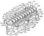
図2は組み立てられた貫通コネクタを示す。端子ハウジング110は面材121に固着されている。隔壁113−115、171−179、及び181−189は、端子ハウジング110の1列目及び2列目の開口(図2には図示せず)の各開口周辺に端子ポケット201−220を形成する。複数のピン(図2では見えない)に取り付けられたスクリュー103とワッシャ104は端子ポケット201−220の底面上に配置され、リード線(図示せず)をピン101に取り付けるための端子コネクタを形成する。
【0026】
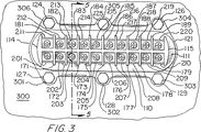
図3は防爆コンパートメント300の開口(図示せず)に嵌合された貫通コネクタを上から見た図である。面材121は、面材121の開口124−129を貫通して伸張するボルト301−306によりコンパートメント300の外側に固着されている。使用されるボルトのタイプに関する設計選定は製作者に任されており、本発明にとって重要なことではない。更に、貫通コネクタ100をコンパートメント壁に締結する際に他の方法を使うこともできる。端子ハウジング110は面材121の表面側に固着される。端子ハウジング110の表面111上の直立壁113−115、171−179、及び181−189は端子ポケット201−220を形成し、各ポケットには複数の導体それぞれに対する端子コネクタが含まれている。
【0027】
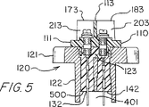
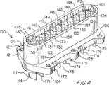
図4は、組み立てられた貫通コネクタ100の底部側を示す斜視図である。各ピンのシャフト102の端部は開口130−149を貫通して伸張し、貫通コネクタ100の裏面から突出している。これにより、ハウジングの製作者は内部回路をハウジング内側のピンに容易に接続することができる。貫通コネクタ100の底面には、爆発又は火炎が開口130−149の内の1つを通り抜けて漏れるのを防ぐために封入物質500(図5に図示)を充填する凹型リザーバ401が設けられている。
【0028】
図5は貫通コネクタ内の封入物質500を示す貫通コネクタの断面図である。封入物質500はエポキシ或いは、火炎又は爆発が開口を抜けて漏れるのを防ぐために貫通コネクタ100の開口を密封するものであれば他の物質であってもよい。図5では、開口132と142により、貫通ベース120の典型的な嵌合開口を示している。最低でも、封入物質500は貫通ベース120の開口を充填せねばならない。本好適実施例では、封入物質500は実質的に凹型リザーバ401のリザーバキャビティとベース120のキャビティ123にも充満して、開口が確実に完全密封されるようにしている。代わりの実施例では、開口を密封するために他の方法を使うことも考慮される。このような代わりの方法の1例として、封入物質500をモールド型に射出して貫通コネクタを成形することにより導体周囲にベースを形成することもできる。
【0029】
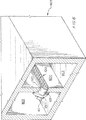
図6は、コンパートメント602と603の共通壁604の開口である開口601内の貫通コネクタ100を示す断面斜視図である。本好適実施例では、防爆コンパートメント602は内部回路部品(図示せず)を含み、コンパートメント603は外部回路部品(図示せず)を含んでいる。貫通コネクタ100は、防爆コンパートメント602内の内部回路部品をコンパートメント603内の外部回路部品に接続する。面材121と端子ハウジング110は壁604に固着されている。貫通ボス122は、開口601を貫通しハウジング602の内部へと伸張している。本好適実施例では、貫通ボス122と開口601は、何れの側でも貫通ボス122と開口601との隙間が貫通ボス122の長さにより決まるように製作される。更に、貫通ボス122の長さは本好適実施例では壁604の厚さに等しい。間隔をこのようにすることにより、開口にガスケットを使用するか他の型式のシール材を使用するかに関わらず、爆発又は火炎が隙間を通って漏れることが防止される。
【0030】
上に開示した実施例は本発明の防爆コネクタの1つの好適な実施例である。ここでは本発明の特定の実施例を開示したが、当業者であれば、文理的或いは均等論的に請求項に述べる範囲内に在る代替防爆コネクタを設計することができ、また設計するであろうことが期待される。
【図面の簡単な説明】
【図1】 本発明の一つの代表的好適実施例の構成要素の分解組立図である。
【図2】 図1の実施例が組み立てられた状態の斜視図である。
【図3】 防爆ハウジング内側の図1の実施例の上面図である。
【図4】 図1の実施例が組み立てられた状態の底面側から見た斜視図である。
【図5】 図1の実施例の断面図である。
【図6】 防爆ハウジング開口内側の図1の実施例の側面斜視図である。[0001]
(Technical field)
The present invention relates to a connector that extends a circuit inside an explosion-proof compartment to a terminal outside the compartment. More precisely, the present invention relates to a penetration connector that is tightly fitted inside the opening of an explosion-proof compartment to prevent flames or internal explosions from passing through or around the penetration connector. Even more strictly, the present invention relates to an explosion-proof penetration connector that prevents arcing between external terminals on the penetration connector.
[0002]
(Background of the Invention)
Some factory environments have an explosive atmosphere. In such an environment, a spark with sufficient energy can cause an explosion. One example of a potential cause of these sparks is the circuitry used to perform or monitor certain actions under these circumstances. Certain circuit components, such as motors, inherently generate sparks during their operation. These inherently sparking circuit components are usually confined within an explosion-proof compartment to prevent the spark generated inside the compartment from adding to the atmosphere outside the compartment.
[0003]
There are challenges in extending the connection from the inherent sparking circuitry in the explosion-proof compartment to the terminals outside the compartment. In order to extend the connection from the inherent sparking circuitry to the terminal, the feedthrough connector must pass through the wall of the explosion-proof compartment without compromising the integrity of the compartment. There are two types of feedthrough connectors commonly used in explosion-proof compartments. The first type of feedthrough connector consists of a plurality of conductors encapsulated in a compartment wall. The second type is a cylindrical through connector that is screwed or slipped into the opening of the compartment. Both of these feedthrough connector types have several disadvantages when used.
[0004]
One disadvantage of the type of encapsulating a conductor in the explosion-proof compartment wall is that it is difficult to properly process the enclosure. The conductor must be held in place while the encapsulating material is injected into the wall of the compartment and cured. Any misalignment of the conductor before the encapsulating material cures will result in an improper mounting of the conductor. Extra time and equipment are required to ensure that the conductor is properly installed.
[0005]
Another disadvantage of the type of encapsulating the conductor in the compartment wall is that once the encapsulating material has hardened, the encapsulating material cannot be easily removed or recreated, so the position of the conductor cannot be changed. is there. If the conductor is defective or the encapsulating material does not cure properly, the entire housing containing the compartment must be discarded. This is a waste of material and is expensive. Yet another disadvantage of the type of encapsulating the conductors in the explosion-proof compartment wall is that the housing structure is limited if the connection between the conductors and the circuitry inside the compartment is facilitated. To facilitate connection with internal circuitry, the conductors must be in an accessible area within the compartment. Placing conductors in accessible areas is a limiting factor in the manufacture of such compartments.
[0006]
The cylindrical through connector is screwed or slipped into a mating opening in the explosion proof compartment. Examples of this type of feedthrough connector are shown in US Pat. No. 5,399,807 and EP 0309895 issued to Yalboro et al. Some of the disadvantages of cylindrical feedthrough connectors are due to the type of conductor used for the feedthrough. Typically, solid conductors such as individual wires or pins are used as conductors in cylindrical through connectors.
[0007]
A disadvantage of the individual wires of the cylindrical through connector is that the individual wires are difficult to handle with automated production techniques. Each individual wire must be attached to a terminal or other type of connector in the explosion-proof compartment. This requires additional hardware in the explosion-proof compartment. Furthermore, connecting individual wires to terminals is a labor intensive operation.
[0008]
The disadvantage of a rigid conductor in a cylindrical feedthrough connector is that it needs to be oriented to facilitate connecting the rigid conductor to the proper circuit. Additional mechanisms are required to make this orientation. Furthermore, the cylindrical feedthrough connector must be located in an easily accessible area within the explosion proof compartment to facilitate orientation.
[0009]
Another disadvantage of using rigid conductors is that the number of rigid conductors in a cylindrical through connector is limited because the round through connector is not space efficient. Furthermore, the arrangement of terminals in accordance with the rigid conductor on the cylindrical through connector is inconvenient for field wiring.
[0010]
Yet another problem with explosion-proof feedthrough connectors is that if adjacent lead wires to the feedthrough connectors are too close together, the energy level of the circuit external to the housing sometimes rises and can generate sparks. .
[0011]
(Summary of Invention)
These and other problems will be solved by the present invention relating to the installation of explosion proof penetration connectors, and the technology in the art will advance. In accordance with the present invention, the feedthrough connector is made to fit tightly into the opening of the explosion proof compartment to prevent an explosion or flame inside the compartment from leaking through or around the feedthrough connector. According to the present invention, the through connector further isolates the terminals on the outside of the through connector from each other in order to prevent sparking between adjacent terminals. The invention also relates to a feedthrough connector having a shape that optimizes the number of terminals while providing the original orientation.
[0012]
The feedthrough connector provided by the present invention has three main elements: a plurality of conductors, a terminal housing, and an explosion-proof base. Each conductor has a terminal on the first outer end of the conductor. A shaft on the second inner end of each conductor extends through the mating opening in the terminal housing and the explosion-proof base and projects into the explosion-proof compartment.
[0013]
A terminal housing made of a non-conductive material is secured to the outside of the explosion-proof base. A plurality of openings through the terminal housing contain the conductor, which is guided into the opening in the terminal housing and fixed in place. The terminal of each conductor remains above the surface of the terminal housing for connection to an external circuit. The openings are arranged on the surface of the terminal housing such that the number of terminals on the housing is maximized.
[0014]
To prevent explosion in the external environment, the terminal housing isolates each terminal from the adjacent terminals to prevent sparking. The U-shaped partition around each terminal prevents a lead wire that is detached from the terminal from contacting another lead wire. The U-shaped partition is delineated by a central wall provided between each row of pins and a separation wall provided between adjacent openings in each row.
[0015]
The explosion-proof base of the through connector is made of a material that can withstand the stress generated by the explosion and is fitted into the opening of the explosion-proof compartment. The explosion-proof base material is fixed to the outer wall of the explosion-proof compartment. The terminal housing is fixed to the surface of the face material of the explosion-proof base. The explosion-proof base penetrating boss protrudes from the back surface of the face material and fits securely into the opening of the explosion-proof compartment. The penetrating boss extends into the explosion-proof compartment. The penetrating boss is manufactured to fit with the explosion-proof compartment with a minimum gap in order to prevent a flame or explosion from leaking through the gap between the explosion-proof compartment and the penetrating boss into the external environment. The opening through the explosion-proof base is paired with the terminal housing opening. The conductor extends through the opening in the terminal housing and further through the opening in the explosion-proof base and protrudes into the explosion-proof compartment. The opening of the explosion-proof base is sealed by injecting an encapsulating material into the space around the conductor in the opening. The encapsulated material prevents a flame or explosion from leaking through each opening.
[0016]
The penetration connector of the present invention is advantageous in the following points as compared with the explosion-proof penetration connector that is generally used. The feedthrough connector of the present invention can be of any shape since the explosion-proof base is made to fit tightly within the opening of the explosion-proof compartment. The terminals on the through connector provided by the present invention are arranged so that the space on the through connector can be used to the maximum extent possible. Since the explosion-proof penetration connector provided by the present invention is a separate component, defects in the penetration connector do not adversely affect the explosion-proof compartment. The present invention can be placed anywhere on the explosion-proof compartment because orientation is not a problem.
[0017]
Detailed Description of the Preferred Embodiment
FIG. 1 is an exploded view of a preferred embodiment of the present invention. The three main components of the explosion-
[0018]
Each of the plurality of conductors has a body extending from the terminal head. The body of each conductor is guided into the
[0019]
In this preferred embodiment, each conductor is a
[0020]
The
[0021]
A U-shaped septum delineated by an upstanding wall on the
[0022]
The
[0023]
The explosion-
[0024]
The through
[0025]
FIG. 2 shows the assembled through connector. The
[0026]
FIG. 3 is a top view of the through connector fitted into the opening (not shown) of the explosion-
[0027]
FIG. 4 is a perspective view showing the bottom side of the assembled through
[0028]
FIG. 5 is a cross-sectional view of the through connector showing the encapsulating
[0029]
FIG. 6 is a cross-sectional perspective view showing the through
[0030]
The embodiment disclosed above is one preferred embodiment of the explosion-proof connector of the present invention. While specific embodiments of the present invention have been disclosed herein, those skilled in the art can and will design alternative explosion-proof connectors that fall within the scope of the claims, either literally or equivalently. It is expected to be.
[Brief description of the drawings]
FIG. 1 is an exploded view of the components of one exemplary preferred embodiment of the present invention.
FIG. 2 is a perspective view showing a state in which the embodiment of FIG. 1 is assembled.
FIG. 3 is a top view of the embodiment of FIG. 1 inside the explosion-proof housing.
4 is a perspective view seen from the bottom side in the assembled state of the embodiment of FIG.
FIG. 5 is a cross-sectional view of the embodiment of FIG.
6 is a side perspective view of the embodiment of FIG. 1 inside the explosion-proof housing opening.
Claims (8)
第1面(111)、第2面(112)及び前記複数の導体(105)を収容するために端子ハウジング(110)を貫通して前記第1面(111)から前記第2面(112)まで伸張する複数の開口(151−160)を有する前記端子ハウジング(110)と、
防爆ベース(120)の各々の開口が前記端子ハウジング(110)を貫通する前記複数の開口(151−160)の対応する1つに嵌合する形状を付与するとともに整列してなる複数の開口(130−149)を有する前記防爆ベース(120)と、
前記防爆ベース(120)内に設けられ、防爆コンパートメント(602)から爆発、火災、火花が抜けて漏れるのを防ぐための封入物質(500)と、
を備え、
前記端子ハウジング(110)の前記第1面(111)及び前記第2面(112)は両端部が円形状で細長く側面部がほぼ平行の卵形をなしており、
前記防爆ベース(120)はその上部(121)が前記端子ハウジング(110)の前記第2面(112)に固着され、その貫通ボス(122)は上記上部(121)に直交して伸長し円形状の両端部が細長く両側部がほぼ平行でほぼ卵形をなし前記防爆コンパートメント(602)の開口に嵌合する形状を有するとともに前記貫通ボス(122)と前記防爆コンパートメントの前記開口との空隙を爆発または火災が抜けて漏れるのを防ぐのに十分な長さを有しており、
前記防爆ベース(120)の前記複数の開口(130−149)は前記上部(121)から前記貫通ボス(122)にかけて前記防爆ベース(120)を貫通し、前記複数の導体(105)の各々が前記端子ハウジング(110)の前記複数の開口(151−160)の1つを貫通し、さらに前記防爆ベース(120)の前記開口(130−149)の対応する1つの開口を貫通するとともに前記貫通ボス(122)の底部から突出しており、
前記封入物質(500)が前記防爆ベース(120)を貫通する前記開口(130−149)の少なくとも内部の前記導体(105)の周りのキャビティを充填するように配置されている
ことを特徴とする、防爆コンパートメント(602)内側の回路を前記防爆コンパートメント(602)外側の回路に接続する防爆貫通コネクタ。A plurality of conductors (105);
The second surface (112) extends from the first surface (111) through the terminal housing (110) to accommodate the first surface (111), the second surface (112), and the plurality of conductors (105). The terminal housing (110) having a plurality of openings (151-160) extending to
A plurality of openings (in which each opening of the explosion-proof base (120) is provided with a shape that fits into a corresponding one of the plurality of openings (151-160) that penetrates the terminal housing (110) and is aligned ( 130-149) said explosion-proof base (120);
An enclosure material (500) provided in the explosion-proof base (120) for preventing explosion, fire, and sparks from leaking out of the explosion-proof compartment (602);
With
The first surface (111) and the second surface (112) of the terminal housing (110) have an oval shape in which both end portions are circular and elongated and side portions are substantially parallel,
The upper part (121) of the explosion-proof base (120) is fixed to the second surface (112) of the terminal housing (110), and the penetrating boss (122) extends perpendicularly to the upper part (121). Both ends of the shape are elongated and both sides are substantially parallel and have an oval shape. The shape is fitted into the opening of the explosion-proof compartment (602), and the gap between the through boss (122) and the opening of the explosion-proof compartment is formed. Long enough to prevent an explosion or fire from leaking out,
The plurality of openings (130-149) of the explosion-proof base (120) pass through the explosion-proof base (120) from the upper part (121) to the through boss (122), and each of the plurality of conductors (105) Passing through one of the plurality of openings (151-160) of the terminal housing (110), and further passing through one corresponding opening of the openings (130-149) of the explosion-proof base (120) and the through hole. Protrudes from the bottom of the boss (122),
The encapsulant (500) is arranged to fill a cavity around the conductor (105) at least inside the openings (130-149) that penetrate the explosion-proof base (120). Explosion-proof penetration connector for connecting the circuit inside the explosion-proof compartment (602) to the circuit outside the explosion-proof compartment (602).
前記防爆ベース(120)の前記上部(121)にあり、前記嵌合リング(117)に嵌合する形状を有し、
前記端子ハウジング(110)を貫通する前記複数の開口(151−160)の各々を前記防爆ベース(120)を貫通する前記複数の開口(130−149)の1つと整列させる凹型キャビティ(123)とを備えていることを特徴とする、請求項1に記載の防爆貫通コネクタ(100)。The terminal housing (110) is defined by an upstanding wall extending perpendicularly to the second surface (112) on the second surface (112), and the upstanding wall extends through the terminal housing (110). A mating ring (117) surrounding the plurality of openings (151-160);
The upper part (121) of the explosion-proof base (120) has a shape to be fitted to the fitting ring (117),
A concave cavity (123) that aligns each of the plurality of openings (151-160) through the terminal housing (110) with one of the plurality of openings (130-149) through the explosion-proof base (120); The explosion-proof penetration connector (100) according to claim 1, characterized by comprising:
前記縦壁に対して直交し、前記端子ハウジング(110)を貫通した前記各列の隣接する前記開口(151−160)の間に配置された複数の壁(171−179、181−189)とを備え、
前記縦壁と前記複数の壁が、前記導体(105)のある端子から外れたリード線と隣接する導線(105)の端子に接続されたリード線との接触を防ぐためのU字型隔壁を輪郭づけてなることを特徴とする請求項6に記載の防爆貫通コネクタ(100)。Between the rows of the plurality of openings (151-160) passing through the terminal housing (110) and substantially with respect to the longitudinal axis of the two sides (111, 112) of the terminal housing (110). Parallel vertical walls (113);
A plurality of walls (171-179, 181-189) disposed between the adjacent openings (151-160) of each row orthogonal to the vertical wall and penetrating the terminal housing (110); With
A U-shaped partition wall for preventing the vertical wall and the plurality of walls from coming into contact with a lead wire connected to a terminal of an adjacent conductor (105) and a lead wire removed from a terminal with the conductor (105) The explosion-proof penetration connector (100) according to claim 6, characterized by being contoured.
ピン(101)と、
前記ピンのヘッド(106)上のスクリュー(103)と、
前記ピンの前記ヘッドに隣接するワッシャ(104)と、
前記ヘッドのねじ穴とを備え、
前記スクリューは、前記ピンと端子接続を行うため、前記ワッシャを貫通して前記ピンのねじ穴内に伸張していることを特徴とする請求項1に記載の防爆貫通コネクタ(100)。Each of the plurality of conductors (105)
Pin (101),
A screw (103) on the head (106) of the pin;
A washer (104) adjacent to the head of the pin;
A screw hole of the head,
The explosion-proof penetration connector (100) according to claim 1, wherein the screw extends through the washer and into a screw hole of the pin for terminal connection with the pin.
Applications Claiming Priority (3)
| Application Number | Priority Date | Filing Date | Title |
|---|---|---|---|
| US08/961,786 | 1997-10-31 | ||
| US08/961,786 US6109979A (en) | 1997-10-31 | 1997-10-31 | Explosion proof feedthrough connector |
| PCT/US1998/022005 WO1999023725A1 (en) | 1997-10-31 | 1998-10-19 | An explosion proof feedthrough connector |
Publications (2)
| Publication Number | Publication Date |
|---|---|
| JP2001522134A JP2001522134A (en) | 2001-11-13 |
| JP3676675B2 true JP3676675B2 (en) | 2005-07-27 |
Family
ID=25504996
Family Applications (1)
| Application Number | Title | Priority Date | Filing Date |
|---|---|---|---|
| JP2000519488A Expired - Fee Related JP3676675B2 (en) | 1997-10-31 | 1998-10-19 | Explosion-proof penetration connector |
Country Status (10)
| Country | Link |
|---|---|
| US (1) | US6109979A (en) |
| EP (1) | EP1027755B1 (en) |
| JP (1) | JP3676675B2 (en) |
| CN (1) | CN1129986C (en) |
| AR (1) | AR013983A1 (en) |
| AU (1) | AU1100199A (en) |
| DE (1) | DE69811388T2 (en) |
| HK (1) | HK1032680A1 (en) |
| MY (1) | MY121019A (en) |
| WO (1) | WO1999023725A1 (en) |
Families Citing this family (38)
| Publication number | Priority date | Publication date | Assignee | Title |
|---|---|---|---|---|
| US6210204B1 (en) * | 1999-12-27 | 2001-04-03 | Hon Hai Precision Ind. Co., Ltd. | Electrical connector having barrier for preventing electrical sparks between adjacent terminals |
| US6206726B1 (en) * | 2000-02-17 | 2001-03-27 | Yazaki North America, Inc. | Tolerance accommodating mounting pad for junction box cover |
| US6556447B2 (en) | 2000-03-01 | 2003-04-29 | Endress + Hauser Flowtec Ag | Electronic apparatus with an enclosure |
| EP1130363A1 (en) * | 2000-03-01 | 2001-09-05 | Endress + Hauser Flowtec AG | Electronic apparatus with a housing |
| US6331674B1 (en) * | 2000-03-31 | 2001-12-18 | Micro Motion, Inc. | Explosion proof terminal block housing that may be opened |
| US6600247B1 (en) * | 2000-09-29 | 2003-07-29 | Reliance Electric Technologies, Llc | Motor stator connection method and apparatus |
| DE10058107A1 (en) * | 2000-11-23 | 2002-06-06 | Werner Riester Gmbh & Co Kg Ar | electrical appliance |
| DE20113501U1 (en) * | 2001-08-14 | 2001-10-11 | Harting Kgaa | Connector with adapter |
| US8538560B2 (en) | 2004-04-29 | 2013-09-17 | Rosemount Inc. | Wireless power and communication unit for process field devices |
| US8145180B2 (en) | 2004-05-21 | 2012-03-27 | Rosemount Inc. | Power generation for process devices |
| US8160535B2 (en) | 2004-06-28 | 2012-04-17 | Rosemount Inc. | RF adapter for field device |
| DE102004036163B4 (en) * | 2004-07-26 | 2016-03-17 | Caterpillar Global Mining Europe Gmbh | Control device for electrohydraulic construction controls |
| US20060254798A1 (en) * | 2005-05-24 | 2006-11-16 | Reed Jim A | Wiring Harness Fire Protection Device |
| DE102008027399A1 (en) * | 2008-06-09 | 2009-12-10 | Mc Technology Gmbh | Multipolar connection terminal |
| US8929948B2 (en) * | 2008-06-17 | 2015-01-06 | Rosemount Inc. | Wireless communication adapter for field devices |
| US8694060B2 (en) | 2008-06-17 | 2014-04-08 | Rosemount Inc. | Form factor and electromagnetic interference protection for process device wireless adapters |
| CA2726707C (en) | 2008-06-17 | 2016-01-19 | Rosemount Inc. | Rf adapter for field device with low voltage intrinsic safety clamping |
| CA2726601C (en) | 2008-06-17 | 2016-08-09 | Rosemount Inc. | Rf adapter for field device with variable voltage drop |
| US7847703B2 (en) * | 2008-11-18 | 2010-12-07 | Rosemount Inc. | Universal process transmitter connector |
| US8626087B2 (en) | 2009-06-16 | 2014-01-07 | Rosemount Inc. | Wire harness for field devices used in a hazardous locations |
| US9674976B2 (en) | 2009-06-16 | 2017-06-06 | Rosemount Inc. | Wireless process communication adapter with improved encapsulation |
| US10761524B2 (en) | 2010-08-12 | 2020-09-01 | Rosemount Inc. | Wireless adapter with process diagnostics |
| DE102011004061A1 (en) * | 2011-02-14 | 2012-08-16 | Endress + Hauser Gmbh + Co. Kg | Electronic device and protective element for use in potentially explosive atmospheres |
| US9310794B2 (en) | 2011-10-27 | 2016-04-12 | Rosemount Inc. | Power supply for industrial process field device |
| DE102012005637B4 (en) * | 2012-03-22 | 2019-02-21 | Krohne Messtechnik Gmbh | gauge |
| KR101828496B1 (en) * | 2012-05-17 | 2018-02-12 | 마이크로 모우션, 인코포레이티드 | Flameproof electrical feed-through |
| CN102664317A (en) * | 2012-05-28 | 2012-09-12 | 深圳市思科赛德电子科技有限公司 | Wiring terminal for preventing screw from falling off and wire holder thereof |
| DE102012108415A1 (en) | 2012-09-10 | 2014-06-12 | Endress + Hauser Flowtec Ag | Interface between a sensor unit and an explosion-proof housing |
| US9209544B2 (en) * | 2013-01-31 | 2015-12-08 | Heraeus Precious Metals Gmbh & Co. Kg | Lead connector with distal frame and method of manufacture |
| US9590400B2 (en) * | 2014-09-30 | 2017-03-07 | Micro Motion, Inc. | Terminal feedthrough |
| CN204809497U (en) * | 2015-03-27 | 2015-11-25 | 富士康(昆山)电脑接插件有限公司 | Electric connector |
| WO2017156233A1 (en) * | 2016-03-10 | 2017-09-14 | Cooper Technologies Company | Explosion-proof enclosure with flame path maintenance and protection means |
| DE102016104739A1 (en) * | 2016-03-15 | 2017-09-21 | Endress + Hauser Flowtec Ag | Field device of measuring and automation technology |
| JP6838306B2 (en) * | 2016-07-08 | 2021-03-03 | 日立金属株式会社 | In-vehicle detection device |
| DE102016125350A1 (en) | 2016-12-22 | 2018-06-28 | Endress+Hauser SE+Co. KG | Connecting element and transmitter housing with inserted therein connecting element |
| US10641624B2 (en) * | 2017-08-30 | 2020-05-05 | Nidec Motor Corporation | Intrinsically-safe, explosion-proof encoder |
| CN108306120B (en) * | 2018-03-05 | 2024-03-19 | 佛山市顺德区美的洗涤电器制造有限公司 | Wire cap bracket assembly |
| US11888255B2 (en) * | 2019-07-15 | 2024-01-30 | Panduit Corp. | Single pair ethernet connector |
Family Cites Families (7)
| Publication number | Priority date | Publication date | Assignee | Title |
|---|---|---|---|---|
| US4213018A (en) * | 1978-06-06 | 1980-07-15 | Crouse-Hinds Company | Explosion-proof contact assembly and method of forming the same |
| GB2208191A (en) * | 1987-07-17 | 1989-03-08 | C M P | Sealed electrical connector |
| DE3732576C2 (en) * | 1987-09-28 | 1995-01-19 | Asea Brown Boveri | Explosion-proof and / or firedamp-protected push-through |
| DE3911901A1 (en) * | 1989-04-12 | 1990-10-18 | Stahl R Schaltgeraete Gmbh | Explosion protected light - has housing with cover that locates on formed projections of base |
| DE4208285A1 (en) * | 1992-03-14 | 1993-09-16 | Cellpack Ag | Electric cable wall entrance seal e.g. for switchgear or cabinet - includes plastic sleeve surrounding cable sheath and locally crimped on to inserted helical support winding |
| US5326285A (en) * | 1992-12-14 | 1994-07-05 | Cooper Industries, Inc. | Connection arrangement between terminal blocks |
| US5399807A (en) * | 1993-08-26 | 1995-03-21 | Cooper Industries, Inc. | Explosion-proof electrical apparatus and method of assembly |
-
1997
- 1997-10-31 US US08/961,786 patent/US6109979A/en not_active Expired - Lifetime
-
1998
- 1998-10-14 MY MYPI98004681A patent/MY121019A/en unknown
- 1998-10-19 EP EP98953684A patent/EP1027755B1/en not_active Expired - Lifetime
- 1998-10-19 JP JP2000519488A patent/JP3676675B2/en not_active Expired - Fee Related
- 1998-10-19 CN CN98810790.2A patent/CN1129986C/en not_active Expired - Lifetime
- 1998-10-19 WO PCT/US1998/022005 patent/WO1999023725A1/en active IP Right Grant
- 1998-10-19 DE DE69811388T patent/DE69811388T2/en not_active Expired - Lifetime
- 1998-10-19 AU AU11001/99A patent/AU1100199A/en not_active Abandoned
- 1998-10-23 AR ARP980105312A patent/AR013983A1/en unknown
-
2001
- 2001-05-09 HK HK01103270A patent/HK1032680A1/en not_active IP Right Cessation
Also Published As
| Publication number | Publication date |
|---|---|
| AR013983A1 (en) | 2001-01-31 |
| DE69811388D1 (en) | 2003-03-20 |
| CN1129986C (en) | 2003-12-03 |
| MY121019A (en) | 2005-12-30 |
| EP1027755A1 (en) | 2000-08-16 |
| EP1027755B1 (en) | 2003-02-12 |
| DE69811388T2 (en) | 2003-07-10 |
| WO1999023725A1 (en) | 1999-05-14 |
| HK1032680A1 (en) | 2001-07-27 |
| CN1278370A (en) | 2000-12-27 |
| JP2001522134A (en) | 2001-11-13 |
| US6109979A (en) | 2000-08-29 |
| AU1100199A (en) | 1999-05-24 |
Similar Documents
| Publication | Publication Date | Title |
|---|---|---|
| JP3676675B2 (en) | Explosion-proof penetration connector | |
| CN101755368B (en) | Waterproof connector, mounting structure for waterproof connector, and mounting method for waterproof connector | |
| JP2995679B2 (en) | Electrical connector | |
| US6372993B1 (en) | Sealed terminal assembly for hermetic compressor | |
| US4775333A (en) | Method of assembling an improved electrical connector | |
| US6368130B1 (en) | Connector adapted to absorb a positional misalignment | |
| JP2019517706A (en) | Three-dimensional connector | |
| US3430182A (en) | Electrical feed-through connection for printed circuit boards and printed cable | |
| KR101169494B1 (en) | Cable bushing device | |
| US5752856A (en) | Sealed fuse connector | |
| JPH0799074A (en) | Electric connector | |
| JPH02174082A (en) | Central distribution panel system for car | |
| KR100272910B1 (en) | Pressure compensation element and terminal strip | |
| US6159041A (en) | Electrical connector assembly for panel mounting | |
| MXPA02000011A (en) | Multiport assembly having a floating electrical circuit board within an enclosure assembly. | |
| EP3582335A1 (en) | Connector assembly, connection module, and method for manufacturing connection module | |
| US20220416478A1 (en) | Shielded connector | |
| US4997392A (en) | Waterproof external connector | |
| JPH0787651B2 (en) | Module electrical equipment | |
| US3833877A (en) | Sockets | |
| CN117316878B (en) | Packaging shell and packaging electronic device | |
| JP2020170672A (en) | Connector mounting structure | |
| CN211017508U (en) | Improved structure of electrical lead connection device | |
| US5847933A (en) | Solderless focus module | |
| CN218300344U (en) | Charging seat shell assembly and charging seat |
Legal Events
| Date | Code | Title | Description |
|---|---|---|---|
| A977 | Report on retrieval |
Free format text: JAPANESE INTERMEDIATE CODE: A971007 Effective date: 20040224 |
|
| A131 | Notification of reasons for refusal |
Free format text: JAPANESE INTERMEDIATE CODE: A131 Effective date: 20040330 |
|
| A601 | Written request for extension of time |
Free format text: JAPANESE INTERMEDIATE CODE: A601 Effective date: 20040629 |
|
| A602 | Written permission of extension of time |
Free format text: JAPANESE INTERMEDIATE CODE: A602 Effective date: 20040706 |
|
| A521 | Request for written amendment filed |
Free format text: JAPANESE INTERMEDIATE CODE: A523 Effective date: 20040729 |
|
| TRDD | Decision of grant or rejection written | ||
| A01 | Written decision to grant a patent or to grant a registration (utility model) |
Free format text: JAPANESE INTERMEDIATE CODE: A01 Effective date: 20050401 |
|
| A61 | First payment of annual fees (during grant procedure) |
Free format text: JAPANESE INTERMEDIATE CODE: A61 Effective date: 20050428 |
|
| R150 | Certificate of patent or registration of utility model |
Free format text: JAPANESE INTERMEDIATE CODE: R150 |
|
| FPAY | Renewal fee payment (event date is renewal date of database) |
Free format text: PAYMENT UNTIL: 20090513 Year of fee payment: 4 |
|
| FPAY | Renewal fee payment (event date is renewal date of database) |
Free format text: PAYMENT UNTIL: 20100513 Year of fee payment: 5 |
|
| FPAY | Renewal fee payment (event date is renewal date of database) |
Free format text: PAYMENT UNTIL: 20110513 Year of fee payment: 6 |
|
| FPAY | Renewal fee payment (event date is renewal date of database) |
Free format text: PAYMENT UNTIL: 20110513 Year of fee payment: 6 |
|
| FPAY | Renewal fee payment (event date is renewal date of database) |
Free format text: PAYMENT UNTIL: 20120513 Year of fee payment: 7 |
|
| FPAY | Renewal fee payment (event date is renewal date of database) |
Free format text: PAYMENT UNTIL: 20120513 Year of fee payment: 7 |
|
| FPAY | Renewal fee payment (event date is renewal date of database) |
Free format text: PAYMENT UNTIL: 20130513 Year of fee payment: 8 |
|
| FPAY | Renewal fee payment (event date is renewal date of database) |
Free format text: PAYMENT UNTIL: 20140513 Year of fee payment: 9 |
|
| R250 | Receipt of annual fees |
Free format text: JAPANESE INTERMEDIATE CODE: R250 |
|
| R250 | Receipt of annual fees |
Free format text: JAPANESE INTERMEDIATE CODE: R250 |
|
| R250 | Receipt of annual fees |
Free format text: JAPANESE INTERMEDIATE CODE: R250 |
|
| R250 | Receipt of annual fees |
Free format text: JAPANESE INTERMEDIATE CODE: R250 |
|
| LAPS | Cancellation because of no payment of annual fees |