JP3674533B2 - Method for monitoring clock synchronization of OSC signal in wavelength division multiplexing system - Google Patents
Method for monitoring clock synchronization of OSC signal in wavelength division multiplexing system Download PDFInfo
- Publication number
- JP3674533B2 JP3674533B2 JP2001125343A JP2001125343A JP3674533B2 JP 3674533 B2 JP3674533 B2 JP 3674533B2 JP 2001125343 A JP2001125343 A JP 2001125343A JP 2001125343 A JP2001125343 A JP 2001125343A JP 3674533 B2 JP3674533 B2 JP 3674533B2
- Authority
- JP
- Japan
- Prior art keywords
- osc signal
- osc
- slip alarm
- mask information
- clock synchronization
- Prior art date
- Legal status (The legal status is an assumption and is not a legal conclusion. Google has not performed a legal analysis and makes no representation as to the accuracy of the status listed.)
- Expired - Fee Related
Links
Images


Classifications
-
- H—ELECTRICITY
- H04—ELECTRIC COMMUNICATION TECHNIQUE
- H04B—TRANSMISSION
- H04B10/00—Transmission systems employing electromagnetic waves other than radio-waves, e.g. infrared, visible or ultraviolet light, or employing corpuscular radiation, e.g. quantum communication
- H04B10/07—Arrangements for monitoring or testing transmission systems; Arrangements for fault measurement of transmission systems
- H04B10/075—Arrangements for monitoring or testing transmission systems; Arrangements for fault measurement of transmission systems using an in-service signal
- H04B10/077—Arrangements for monitoring or testing transmission systems; Arrangements for fault measurement of transmission systems using an in-service signal using a supervisory or additional signal
- H04B10/0775—Performance monitoring and measurement of transmission parameters
-
- H—ELECTRICITY
- H04—ELECTRIC COMMUNICATION TECHNIQUE
- H04J—MULTIPLEX COMMUNICATION
- H04J14/00—Optical multiplex systems
- H04J14/02—Wavelength-division multiplex systems
- H04J14/0227—Operation, administration, maintenance or provisioning [OAMP] of WDM networks, e.g. media access, routing or wavelength allocation
- H04J14/0241—Wavelength allocation for communications one-to-one, e.g. unicasting wavelengths
- H04J14/0242—Wavelength allocation for communications one-to-one, e.g. unicasting wavelengths in WDM-PON
- H04J14/0245—Wavelength allocation for communications one-to-one, e.g. unicasting wavelengths in WDM-PON for downstream transmission, e.g. optical line terminal [OLT] to ONU
- H04J14/0246—Wavelength allocation for communications one-to-one, e.g. unicasting wavelengths in WDM-PON for downstream transmission, e.g. optical line terminal [OLT] to ONU using one wavelength per ONU
-
- H—ELECTRICITY
- H04—ELECTRIC COMMUNICATION TECHNIQUE
- H04J—MULTIPLEX COMMUNICATION
- H04J14/00—Optical multiplex systems
- H04J14/02—Wavelength-division multiplex systems
- H04J14/0227—Operation, administration, maintenance or provisioning [OAMP] of WDM networks, e.g. media access, routing or wavelength allocation
- H04J14/0241—Wavelength allocation for communications one-to-one, e.g. unicasting wavelengths
- H04J14/0242—Wavelength allocation for communications one-to-one, e.g. unicasting wavelengths in WDM-PON
- H04J14/0249—Wavelength allocation for communications one-to-one, e.g. unicasting wavelengths in WDM-PON for upstream transmission, e.g. ONU-to-OLT or ONU-to-ONU
- H04J14/025—Wavelength allocation for communications one-to-one, e.g. unicasting wavelengths in WDM-PON for upstream transmission, e.g. ONU-to-OLT or ONU-to-ONU using one wavelength per ONU, e.g. for transmissions from-ONU-to-OLT or from-ONU-to-ONU
-
- H—ELECTRICITY
- H04—ELECTRIC COMMUNICATION TECHNIQUE
- H04B—TRANSMISSION
- H04B2210/00—Indexing scheme relating to optical transmission systems
- H04B2210/07—Monitoring an optical transmission system using a supervisory signal
- H04B2210/071—Monitoring an optical transmission system using a supervisory signal using alarms
-
- H—ELECTRICITY
- H04—ELECTRIC COMMUNICATION TECHNIQUE
- H04J—MULTIPLEX COMMUNICATION
- H04J14/00—Optical multiplex systems
- H04J14/02—Wavelength-division multiplex systems
- H04J14/0278—WDM optical network architectures
- H04J14/0279—WDM point-to-point architectures
Abstract
Description
【0001】
【発明の属する技術分野】
本発明は、波長多重システムにおけるクロック同期監視のための技術に関する。
【0002】
【従来の技術】
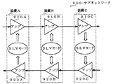
従来、装置間の管理メッセージやユーザデータの転送をOSC(Optical Supervisory Channel)信号の通信により実現するための波長多重システムのサブネットワークは、例えば図3に示すように構成されている。
図3において、サブネットワーク900は、順次に接続された複数個、図示の場合、三個の装置A,装置Bおよび装置Cを備えており、これらの装置A,BおよびCは、それぞれ双方向の通信のためのアンプ910A,920A,910B,920B,910C,920Cを備えている。
【0003】
そして、装置Aは、クロックマスタとしてINTモードに設定されると共に、装置B,Cは、装置Aに従属同期するようにSLVモードに設定されている。
これにより、装置Aは、自己の発生するクロック信号に基づいて、アンプ910Aが動作すると共に、装置Bおよび装置Cは、装置Aのアンプ910Aから伝送路を介してOSC信号と共に送られてくるクロック信号に同期して動作するようになっている。
【0004】
【発明が解決しようとする課題】
ところで、図4に示すように、例えば装置Aから装置Bへの片方向の伝送路に障害が発生した場合、この伝送路の下流に位置する装置、すなわち装置Bおよび装置Cには、装置Aのクロック信号が送られてこなくなるため、装置Aのクロック信号を使用できなくなってしまう。
このため、装置Bは、SLVモードからINTモードに切り替わって、新たなクロックマスタとなり、装置Cは、装置Bのクロック信号が送られてくることにより、この装置Bのクロック信号と同期して動作するようになる。
これにより、装置B,装置C間では、新たなクロック同期が成立することになる。
【0005】
しかしながら、このとき、装置Bから装置Aへの片方向の伝送路は有効であることから、装置Bから装置AにはOSC信号が伝送されている。その際、装置Bは、自己のクロック信号に同期して動作しているので、装置Bから装置Aに伝送されるOSC信号は、装置Bのクロック信号に同期していることになる。
したがって、装置Aと装置Bの間におけるクロック同期が成立しなくなり、装置Aでは、所謂スリップアラームを発生するようになっているが、このスリップアラームは、伝送路障害により発生する二次的な不要アラームである。
【0006】
本発明は、上記の問題を解決すべくなされたものであり、伝送路障害によりスリップアラームが発生した場合、このスリップアラームをマスクして、OSC通信における最適なクロック同期監視を行なうようにした、波長多重システムにおけるOSC信号のクロック同期監視方法の提供を目的とする。
【0007】
【課題を解決するための手段】
この目的を達成するため、本発明の請求項1記載のOSC信号のクロック同期監視方法は、順次に接続された複数の装置間の管理メッセージやユーザデータの転送を、クロック同期したOSC通信により行なうようにした波長多重システムにおいて、各装置が、上流側の対向装置から入力されるクロック信号を監視することにより伝送路障害を検出すると、当該装置のクロックモードをクロックマスタに切り換えて、OSC信号にスリップアラームマスク情報を挿入して、順次の対向装置に送信し、各対向装置が、受信したOSC信号からスリップアラームマスク情報を取り出して、スリップアラームをマスクするとともに、OSC信号にスリップアラームマスク情報を挿入して、順次の対向装置に送信する構成としてある。
【0008】
OSC信号のクロック同期監視方法をこのような構成とすると、伝送路障害発生時に、OSC信号にスリップアラームマスク情報を挿入して、対向装置に送信することにより、対向装置は、受信したOSC信号からスリップアラームマスク情報を取り出して、このスリップアラームマスク情報に基づいてスリップアラームをマスクする。これにより、伝送路障害発生時に、伝送路障害により発生する二次的な不要アラームであるスリップアラームの発生が抑止されることになる。したがって、不要なアラームであるスリップアラームが発生しないので、OSC信号のクロック同期の監視をより適切に行なうことが可能になると共に、最適な保守を行なうことができる。
【0009】
請求項2記載のOSC信号のクロック同期監視方法は、各装置が、OSC信号処理部を備えており、このOSC信号処理部が、伝送路障害発生時に、OSC信号にスリップアラームマスク情報を挿入して、対向装置に送信すると共に、受信したOSC信号からスリップアラームマスク情報を取り出して、スリップアラームをマスクする構成としてある。
OSC信号のクロック同期監視方法をこのような構成とすると、OSC信号処理部によって、伝送路障害発生時のスリップアラームマスク情報の挿入と、受信したOSC信号からのスリップアラームマスク情報の取出し、そしてスリップアラームのマスクを行なうことができる。
【0010】
請求項3記載のOSC信号のクロック同期監視方法は、上記OSC信号処理部が、受信したOSC信号に基づいて、伝送路障害を検出し、送信すべきOSC信号にスリップアラームマスク情報を挿入して送信する構成としてある。
OSC信号のクロック同期監視方法をこのような構成とすると、各装置のOSC信号処理部が、それぞれ上流側の装置から送信されてくるOSC信号を受信して、このOSC信号に基づいて、伝送路障害を検出することにより、送信するOSC信号にスリップアラームマスク情報を挿入するので、各装置にて伝送路障害の検出を行ない、伝送路障害発生時には、OSC信号にスリップアラームマスク情報が挿入されることにより、他の装置におけるスリップアラームの発生を抑止することができる。
【0011】
請求項4記載のOSC信号のクロック同期監視方法は、上記OSC信号処理部が、受信したOSC信号により伝送路障害を検出したとき、当該装置をSLVモードからINTモードに切換える構成としてある。
OSC信号のクロック同期監視方法をこのような構成とすると、伝送路障害が発生したとき、これを検出した装置がSLVモードからINTモードに切換えられることにより、当該装置が新たなクロックマスタとなってクロック信号を発生し、このクロック信号に基づいてOSC信号を送信することになる。
【0012】
請求項5記載のOSC信号のクロック同期監視方法は、上記OSC信号処理部が、受信したOSC信号にスリップアラームマスク情報が挿入されているとき、スリップアラーム発生をマスクする構成としてある。
OSC信号のクロック同期監視方法をこのような構成とすると、受信したOSC信号にスリップアラームマスク情報が挿入されているとき、OSC信号処理部がスリップアラームの発生をマスクするので、伝送路障害発生時に不要なアラームであるスリップアラームの発生を抑止することができる。これにより、OSC信号のクロック同期の監視をより適切に行なうことが可能になると共に、最適な保守を行なうことができる。
【0013】
なお、本発明のOSC信号のクロック同期監視方法は、上記OSC信号処理部が、受信したOSC信号を解析して、管理メッセージおよびユーザデータを取り出して活用することができる。
すなわち、各装置のOSC信号処理部が、受信したOSC信号から管理メッセージおよびユーザデータを取り出して、適宜に活用することができる。
【0014】
【発明の実施の形態】
以下、本発明の実施の形態について、図面を参照して説明する。
まず、本発明によるOSC信号のクロック同期監視方法の一実施形態を適用する波長多重システムのサブネットワークを、図1を参照して説明する。
図1は、上記サブネットワークの構成を示すブロック図である。
【0015】
図1に示すように、サブネットワーク10は、順次に伝送路により接続される三つの装置100,200,300を設けてある。
【0016】
図1において、左端の第一の装置100は、OMUX部110と、送信用のアンプ120と、受信側のアンプ130と、ODMUX部140と、OSC信号処理部150と、を設けてある。
【0017】
また、図1において、中央の第二の装置200は、二つのアンプ210,220と、OSC信号処理部230と、を設けてある。
この場合、二つのアンプ210,220は、それぞれ送信側および受信側のアンプとして作用して、互いに双方向でOSC信号処理部230に対してOSC信号の分波,処理そして合波を行なうようになっている。
【0018】
さらに、図1において、右端の第三の装置300は、上述した第一の装置100と同様に、OMUX部310と、送信側のアンプ320と、受信側のアンプ330と、ODMUX部340と、OSC信号処理部350と、を設けてある。
【0019】
ここで、上記OMUX部110,310は、入力される複数の信号を波長多重して、一つの信号として出力するようになっている。
【0020】
また、送信側のアンプ120,320は、OMUX部110,310からの信号を増幅すると共に、OSC信号処理部150,350からのOSC信号を合波して、装置200に対して出力するようになっている。
【0021】
これに対して、受信側のアンプ130,330は、装置200から入力される信号を増幅すると共に、信号中に含まれるOSC信号を分波して、OSC信号処理部150,350に出力するようになっている。
【0022】
さらに、ODMUX部140,340は、受信側のアンプ130,330からの信号を分波して、各信号をそれぞれ別個に出力するようになっている。
【0023】
また、第二の装置200の二つのアンプ210,220のうち、第一のアンプ210は、第一の装置100から入力される信号を増幅し、さらに信号中に含まれるOSC信号を分波して、OSC信号処理部230に出力すると共に、OSC信号処理部230からのOSC信号を合波して、第三の装置300に対して出力するようになっている。
【0024】
これに対して、第二のアンプ220は、第三の装置300から入力される信号を増幅し、さらに信号中に含まれるOSC信号を分波して、OSC信号処理部230に出力すると共に、OSC信号処理部230からのOSC信号を合波して、第一の装置100に対して出力するようになっている。
【0025】
ここで、上記各アンプ120,130,210,220,320,330、そしてOMUX部110,310およびODMUX部140,340は、それぞれ公知の構成のものを用いているので、詳細な説明については省略する。
【0026】
上記OSC信号処理部150,350は、同じ構成であるから、OSC信号処理部150について、以下に図2を参照して説明する。
OSC信号処理部150は、OSC受信部151と、クロックモード制御部152と、受信データ解析部153と、スリップ検出部154と、管理メッセージ/ユーザデータインタフェース部155と、送信データ生成部156と、OSC送信部157と、を設けてある。
【0027】
上記OSC受信部151は、受信側のアンプ130で分波されたOSC信号を受信して、受信データ解析部153に出力すると共に、伝送路障害を検出する。
そして、OSC受信部151は、伝送路障害を検出した場合、伝送路障害検出をクロックモード制御部152および送信データ生成部156に通知する。
【0028】
上記クロックモード制御部152は、OSC受信部151から伝送路障害検出の通知を受けたとき、装置100のクロックモードをSLVモードからINTモードに切換えるようになっている。
【0029】
上記受信データ解析部153は、OSC受信部151から入力されるOSC信号を解析し、クロック同期を監視すると共に、解析したデータを管理メッセージ/ユーザデータインタフェース部155に送出する。
さらに、上記受信データ解析部153は、データ解析によりOSC信号に挿入されたスリップアラームマスク情報を取り出した場合には、その旨をスリップ検出部154に通知する。
【0030】
上記スリップ検出部154は、受信データ解析部153からスリップアラームマスク情報検出の通知があったとき、OSC受信部151が発生するスリップアラームをマスクする。
【0031】
上記管理メッセージ/ユーザデータインタフェース部155は、受信データ解析部153で解析されたデータ(管理メッセージ/ユーザデータ)を受け取って、これらのデータを活用し、必要に応じて適宜にデータを修正する。
そして、管理メッセージ/ユーザデータインタフェース部155は、活用の結果としての管理メッセージ/ユーザデータを送信データ生成部156に対して送出する。
【0032】
上記送信データ生成部156は、管理メッセージ/ユーザデータインタフェース部155からの管理メッセージ/ユーザデータに基づいて送信データとしてのOSC信号を生成すると共に、OSC受信部151から伝送路障害検出の通知を受け取ったときには、上記OSC信号にスリップアラームマスク情報を挿入する。
【0033】
上記OSC送信部157は、送信データ生成部156からのOSC信号を、伝送路の送信側のアンプ120に送信する。
【0034】
OSC信号処理部350も、上述したOSC信号処理部150と同様に動作し、またOSC信号処理部230は、二つのアンプ210,220間にて双方向でOSC信号処理部150と同様に動作するようになっている。
【0035】
次に、上述した波長多重システムのサブネットワーク10における本発明によるOSC信号のクロック同期監視方法について、説明する。
図1にて、装置100がクロックマスタとしてINTモードに設定されると共に、装置200,300が、装置100に従属同期するようにSLVモードに設定されている。
【0036】
これにより、装置100は、自己の発生するクロック信号に基づいて、送信側のアンプ120が動作して、OMUX部110からの波長多重信号を増幅すると共に、OSC信号処理部150からのOSC信号を合波して、装置200を介して、装置300に伝送する。
そして、装置300は、受信側のアンプ330からの出力信号をODMUX部340により波長多重された各信号を分波して、各信号をそれぞれ別個に出力する。
この場合、各装置200,300は、伝送されてくるOSC信号に含まれるクロック信号に基づいて従属同期するようになっている。
【0037】
同様にして、装置300は、受信した装置100のクロック信号に基づいて、送信側のアンプ320が動作して、OMUX部310からの波長多重信号を増幅すると共に、OSC信号処理部350からのOSC信号を合波して、装置200を介して、装置100に伝送する。
【0038】
そして、装置100は、受信側のアンプ130からの出力信号をODMUX部140により波長多重された各信号を分波して、各信号をそれぞれ別個に出力する。
この場合、装置200は、伝送されてくるOSC信号に含まれるクロック信号に基づいて従属同期すると共に、装置100は、自己の発生するクロック信号に同期するようになっている。
【0039】
ここで、例えば、図4に示す場合と同様にして、装置100から装置200への片方向の伝送路に障害が発生すると、この伝送路の下流に位置する装置200には、装置100のクロック信号が送られてこなくなる。
このため、装置200は、そのOSC信号処理部230がクロックモード制御部を制御することにより、SLVモードからINTモードに切換えられ、装置200が新たなクロックマスタとなって、装置300には、装置200のクロック信号が送られてくる。
【0040】
これにより、装置200,300間では、新たなクロック同期が成立し、信号伝送が行なわれ得る。
その際、OSC信号処理部230は、OSC信号にスリップアラームマスク情報を挿入して、OSC信号を生成する。
【0041】
ところで、装置200から装置100への伝送路には、装置200から、装置200のクロック信号に基づいて、OSC信号が伝送されるので、装置100,200間ではクロック同期が成立しなくなり、スリップが発生することになるが、装置200からのOSC信号には、スリップアラームマスク情報が挿入されている。
したがって、装置100のOSC信号処理部150において、このスリップアラームマスク情報が取り出されることにより、スリップアラームの発生がマスクされる。
これにより、伝送路障害発生による二次的な不要なアラームであるスリップアラームの発生が抑止されるので、より適切なクロック同期監視を行なうことができる。
【0045】
上述した実施形態においては、サブネットワーク10は、互いに信号の送受信を行なう装置100,300の間に、一つの中継用の装置200が設けられているが、これに限らず、順次に複数の中継用の装置が設けられていてもよい。
【0046】
【発明の効果】
以上のように、本発明によれば、伝送路障害発生時に、OSC信号にスリップアラームマスク情報を挿入して、対向装置に送信することにより、対向装置は、受信したOSC信号からスリップアラームマスク情報を取り出して、このスリップアラームマスク情報に基づいてスリップアラームをマスクする。これにより、伝送路障害発生時に、伝送路障害により発生する二次的な不要アラームであるスリップアラームの発生が抑止されることになる。したがって、不要なアラームであるスリップアラームが発生しないので、OSC信号のクロック同期の監視をより適切に行なうことが可能になると共に、最適な保守を行なうことができる。
このようにして、伝送路障害によりスリップアラームが発生した場合、このスリップアラームをマスクして、OSC通信における最適なクロック同期監視を行なうことができる。
【図面の簡単な説明】
【図1】本発明によるOSC信号のクロック同期監視方法の一実施形態を適用した波長多重システムのサブネットワークの構成を示すブロック図である。
【図2】図1のサブネットワークにおける各装置のOSC信号処理部の構成を示すブロック図である。
【図3】従来の波長多重システムのサブネットワークの構成を示すブロック図である。
【図4】図3の波長多重システムのサブネットワークにおける伝送路障害発生の状態を示すブロック図である。
【符号の説明】
10 波長多重システムのサブネットワーク
100,200,300 装置
110,310 OMUX部
120,320 送信側のアンプ
130,330 受信側のアンプ
140,340 ODMUX部
150,230,350 OSC信号処理部
210,220 アンプ[0001]
BACKGROUND OF THE INVENTION
The present invention relates to a technique for clock synchronization monitoring in a wavelength division multiplexing system.
[0002]
[Prior art]
2. Description of the Related Art Conventionally, a sub-network of a wavelength multiplexing system for realizing management message and user data transfer between devices by communication of an OSC (Optical Supervision Channel) signal is configured as shown in FIG. 3, for example.
In FIG. 3, the
[0003]
Device A is set to the INT mode as a clock master, and devices B and C are set to the SLV mode so as to be subordinately synchronized with device A.
As a result, the device A operates the amplifier 910A based on the clock signal generated by itself, and the devices B and C receive the clocks sent from the amplifier 910A of the device A together with the OSC signal via the transmission line. It operates in synchronization with the signal.
[0004]
[Problems to be solved by the invention]
By the way, as shown in FIG. 4, for example, when a failure occurs in a one-way transmission path from the apparatus A to the apparatus B, the apparatuses located downstream of the transmission path, that is, the apparatuses B and C, include the apparatus A Therefore, the clock signal of the device A cannot be used.
For this reason, the device B switches from the SLV mode to the INT mode and becomes a new clock master, and the device C operates in synchronization with the clock signal of the device B by receiving the clock signal of the device B. To come.
As a result, a new clock synchronization is established between the devices B and C.
[0005]
However, at this time, since the one-way transmission path from the device B to the device A is effective, the OSC signal is transmitted from the device B to the device A. At this time, since the device B operates in synchronization with its own clock signal, the OSC signal transmitted from the device B to the device A is synchronized with the clock signal of the device B.
Therefore, the clock synchronization between the device A and the device B is not established, and the device A generates a so-called slip alarm, but this slip alarm is a secondary unnecessary generated due to a transmission path failure. It is an alarm.
[0006]
The present invention has been made to solve the above problem, and when a slip alarm occurs due to a transmission line failure, the slip alarm is masked to perform optimum clock synchronization monitoring in OSC communication. An object of the present invention is to provide a clock synchronization monitoring method for OSC signals in a wavelength division multiplexing system.
[0007]
[Means for Solving the Problems]
To achieve this object, the clock synchronization monitoring method for an OSC signal according to
[0008]
When the clock synchronization monitoring method of the OSC signal is configured as described above, when the transmission path failure occurs, slip alarm mask information is inserted into the OSC signal and transmitted to the opposite device, so that the opposite device can receive the received OSC signal from the received OSC signal. The slip alarm mask information is taken out, and the slip alarm is masked based on the slip alarm mask information. As a result, when a transmission line failure occurs, the occurrence of a slip alarm that is a secondary unnecessary alarm that occurs due to the transmission line failure is suppressed. Therefore, since a slip alarm, which is an unnecessary alarm, does not occur, it is possible to more appropriately monitor the clock synchronization of the OSC signal and perform optimum maintenance.
[0009]
According to the clock synchronization monitoring method for an OSC signal according to
When the clock synchronization monitoring method of the OSC signal has such a configuration, the OSC signal processing unit inserts slip alarm mask information when a transmission line failure occurs, extracts slip alarm mask information from the received OSC signal, and slips. Alarm masking can be performed.
[0010]
The clock synchronization monitoring method for an OSC signal according to
When the OSC signal clock synchronization monitoring method has such a configuration, the OSC signal processing unit of each device receives the OSC signal transmitted from the upstream device, and the transmission path is based on the OSC signal. By detecting a failure, slip alarm mask information is inserted into the OSC signal to be transmitted. Therefore, a transmission line failure is detected by each device, and slip alarm mask information is inserted into the OSC signal when a transmission line failure occurs. As a result, the occurrence of a slip alarm in other devices can be suppressed.
[0011]
According to a fourth aspect of the present invention, the OSC signal clock synchronization monitoring method switches the apparatus from the SLV mode to the INT mode when the OSC signal processing unit detects a transmission line failure by the received OSC signal.
If the clock synchronization monitoring method for the OSC signal has such a configuration, when a transmission line failure occurs, the device that detects the failure is switched from the SLV mode to the INT mode, so that the device becomes a new clock master. A clock signal is generated, and an OSC signal is transmitted based on the clock signal.
[0012]
The OSC signal clock synchronization monitoring method according to
When the OSC signal clock synchronization monitoring method has such a configuration, when slip alarm mask information is inserted in the received OSC signal, the OSC signal processing unit masks the occurrence of the slip alarm. The occurrence of slip alarms, which are unnecessary alarms, can be suppressed. This makes it possible to more appropriately monitor the clock synchronization of the OSC signal and perform optimum maintenance.
[0013]
In the OSC signal clock synchronization monitoring method of the present invention, the OSC signal processing unit can analyze the received OSC signal and extract and use the management message and user data .
That is, the OSC signal processing unit of each device can extract the management message and user data from the received OSC signal and use them appropriately.
[0014]
DETAILED DESCRIPTION OF THE INVENTION
Embodiments of the present invention will be described below with reference to the drawings.
First, a sub-network of a wavelength division multiplexing system to which an embodiment of the OSC signal clock synchronization monitoring method according to the present invention is applied will be described with reference to FIG.
FIG. 1 is a block diagram showing the configuration of the subnetwork.
[0015]
As shown in FIG. 1, the
[0016]
In FIG. 1, the first apparatus 100 at the left end includes an OMUX unit 110, a
[0017]
In FIG. 1, the second device 200 at the center is provided with two
In this case, the two
[0018]
Further, in FIG. 1, the third apparatus 300 at the right end, like the first apparatus 100 described above, includes an OMUX unit 310, a transmission-
[0019]
Here, the OMUX units 110 and 310 wavelength-multiplex a plurality of input signals and output the signals as one signal.
[0020]
Further, the
[0021]
On the other hand, the receiving-
[0022]
Further, the
[0023]
Of the two
[0024]
On the other hand, the
[0025]
Here, the
[0026]
Since the OSC
The OSC
[0027]
The OSC receiving unit 151 receives the OSC signal demultiplexed by the receiving-side amplifier 130, outputs the received OSC signal to the received data analyzing unit 153, and detects a transmission path failure.
When the OSC reception unit 151 detects a transmission line failure, the OSC reception unit 151 notifies the clock
[0028]
The clock
[0029]
The reception data analysis unit 153 analyzes the OSC signal input from the OSC reception unit 151, monitors clock synchronization, and sends the analyzed data to the management message / user data interface unit 155.
Further, when the received data analysis unit 153 retrieves slip alarm mask information inserted into the OSC signal by data analysis, the reception data analysis unit 153 notifies the slip detection unit 154 to that effect.
[0030]
The slip detection unit 154 masks a slip alarm generated by the OSC reception unit 151 when the reception data analysis unit 153 receives notification of slip alarm mask information detection.
[0031]
The management message / user data interface unit 155 receives the data (management message / user data) analyzed by the received data analysis unit 153, utilizes these data, and corrects the data as necessary.
Then, the management message / user data interface unit 155 sends the management message / user data as a result of utilization to the transmission
[0032]
The transmission
[0033]
The OSC transmission unit 157 transmits the OSC signal from the transmission
[0034]
The OSC signal processing unit 350 also operates in the same manner as the OSC
[0035]
Next, an OSC signal clock synchronization monitoring method according to the present invention in the
In FIG. 1, the device 100 is set to the INT mode as a clock master, and the devices 200 and 300 are set to the SLV mode so as to be subordinately synchronized with the device 100.
[0036]
As a result, the apparatus 100 operates the
The apparatus 300 demultiplexes each signal obtained by wavelength multiplexing the output signal from the receiving-
In this case, the devices 200 and 300 are dependently synchronized based on the clock signal included in the transmitted OSC signal.
[0037]
Similarly, in the device 300, the transmission-
[0038]
The apparatus 100 demultiplexes each signal obtained by wavelength multiplexing the output signal from the receiving-side amplifier 130 by the ODMUX unit 140, and outputs each signal separately.
In this case, the device 200 is dependently synchronized based on the clock signal included in the transmitted OSC signal, and the device 100 is synchronized with the clock signal generated by itself.
[0039]
Here, for example, when a failure occurs in the one-way transmission path from the apparatus 100 to the apparatus 200, as in the case shown in FIG. 4, the apparatus 200 located downstream of the transmission path includes the clock of the apparatus 100. No signal is sent.
Therefore, the device 200 is switched from the SLV mode to the INT mode by the OSC signal processing unit 230 controlling the clock mode control unit, and the device 200 becomes a new clock master. 200 clock signals are sent.
[0040]
Thus, a new clock synchronization is established between the devices 200 and 300, and signal transmission can be performed.
At that time, the OSC signal processing unit 230 inserts slip alarm mask information into the OSC signal to generate an OSC signal.
[0041]
By the way, since the OSC signal is transmitted from the device 200 to the transmission path from the device 200 to the device 100 based on the clock signal of the device 200, clock synchronization is not established between the devices 100 and 200, and slipping occurs. The slip alarm mask information is inserted into the OSC signal from the apparatus 200.
Therefore, the OSC
As a result, the occurrence of a slip alarm, which is a secondary unnecessary alarm due to the occurrence of a transmission path failure, is suppressed, so that more appropriate clock synchronization monitoring can be performed.
[0045]
In the embodiment described above, the
[0046]
【The invention's effect】
As described above, according to the present invention, when a transmission path failure occurs, slip alarm mask information is inserted into the OSC signal and transmitted to the opposite device, so that the opposite device can detect the slip alarm mask information from the received OSC signal. The slip alarm is masked based on the slip alarm mask information. As a result, when a transmission line failure occurs, the occurrence of a slip alarm, which is a secondary unnecessary alarm caused by the transmission line failure, is suppressed. Accordingly, since an unnecessary slip alarm, which is an unnecessary alarm, does not occur, it is possible to more appropriately monitor the clock synchronization of the OSC signal and perform optimum maintenance.
In this way, when a slip alarm occurs due to a transmission path failure, this slip alarm can be masked and optimal clock synchronization monitoring in OSC communication can be performed.
[Brief description of the drawings]
FIG. 1 is a block diagram showing the configuration of a sub-network of a wavelength division multiplexing system to which an embodiment of a clock synchronization monitoring method for OSC signals according to the present invention is applied.
2 is a block diagram showing a configuration of an OSC signal processing unit of each device in the sub-network of FIG.
FIG. 3 is a block diagram showing a configuration of a subnetwork of a conventional wavelength division multiplexing system.
4 is a block diagram showing a state where a transmission path failure has occurred in the sub-network of the wavelength division multiplexing system of FIG. 3;
[Explanation of symbols]
10 Sub-network 100, 200, 300 of wavelength multiplexing system 110, 310
Claims (5)
各装置が、上流側の対向装置から入力されるクロック信号を監視することにより伝送路障害を検出すると、当該装置のクロックモードをクロックマスタに切り換えて、OSC信号にスリップアラームマスク情報を挿入して、順次の対向装置に送信し、
各対向装置が、受信したOSC信号からスリップアラームマスク情報を取り出して、スリップアラームをマスクするとともに、OSC信号にスリップアラームマスク情報を挿入して、順次の対向装置に送信することを特徴とする波長多重システムにおけるOSC信号のクロック同期監視方法。In a wavelength division multiplexing system in which management messages and user data are transferred between a plurality of devices connected in series by OSC communication synchronized with clocks.
When each device detects a transmission path failure by monitoring the clock signal input from the upstream opposite device, it switches the clock mode of the device to the clock master and inserts slip alarm mask information into the OSC signal. , Send to the opposite device sequentially ,
Each counter device extracts slip alarm mask information from the received OSC signal, masks the slip alarm, inserts the slip alarm mask information into the OSC signal, and transmits to the sequential counter device A method for monitoring clock synchronization of OSC signals in a multiple system.
このOSC信号処理部が、伝送路障害発生時に、OSC信号にスリップアラームマスク情報を挿入して、対向装置に送信すると共に、受信したOSC信号からスリップアラームマスク情報を取り出して、スリップアラームをマスクすることを特徴とする請求項1に記載の波長多重システムにおけるOSC信号のクロック同期監視方法。Each device has an OSC signal processor,
This OSC signal processing unit inserts slip alarm mask information into the OSC signal when a transmission line failure occurs and transmits the slip alarm mask information to the opposite device, and also extracts slip alarm mask information from the received OSC signal to mask the slip alarm. The method of monitoring clock synchronization of an OSC signal in a wavelength division multiplexing system according to claim 1.
Priority Applications (4)
| Application Number | Priority Date | Filing Date | Title |
|---|---|---|---|
| JP2001125343A JP3674533B2 (en) | 2001-04-24 | 2001-04-24 | Method for monitoring clock synchronization of OSC signal in wavelength division multiplexing system |
| TW91107643A TW574788B (en) | 2001-04-24 | 2002-04-15 | Clock synchronization supervisory method of OSC signal in wavelength multiplexing system and wavelength multiplexing system using that method |
| US10/127,444 US20020154358A1 (en) | 2001-04-24 | 2002-04-23 | Clock synchronization supervisory method of OSC signal in wavelength multiplexing system and wavelength multiplexing system using that method |
| CNB021184607A CN1224192C (en) | 2001-04-24 | 2002-04-24 | Clock synchronous monitoring method and system for OSC signal in wavelength multiplexing system |
Applications Claiming Priority (1)
| Application Number | Priority Date | Filing Date | Title |
|---|---|---|---|
| JP2001125343A JP3674533B2 (en) | 2001-04-24 | 2001-04-24 | Method for monitoring clock synchronization of OSC signal in wavelength division multiplexing system |
Publications (2)
| Publication Number | Publication Date |
|---|---|
| JP2002319909A JP2002319909A (en) | 2002-10-31 |
| JP3674533B2 true JP3674533B2 (en) | 2005-07-20 |
Family
ID=18974583
Family Applications (1)
| Application Number | Title | Priority Date | Filing Date |
|---|---|---|---|
| JP2001125343A Expired - Fee Related JP3674533B2 (en) | 2001-04-24 | 2001-04-24 | Method for monitoring clock synchronization of OSC signal in wavelength division multiplexing system |
Country Status (4)
| Country | Link |
|---|---|
| US (1) | US20020154358A1 (en) |
| JP (1) | JP3674533B2 (en) |
| CN (1) | CN1224192C (en) |
| TW (1) | TW574788B (en) |
Families Citing this family (6)
| Publication number | Priority date | Publication date | Assignee | Title |
|---|---|---|---|---|
| US7339723B2 (en) * | 2004-03-31 | 2008-03-04 | Nec Corporation | Optical transmission system, optical repeating apparatus, and quality supervising method |
| JP4863649B2 (en) | 2005-06-01 | 2012-01-25 | 富士通株式会社 | LAN signal transmission method and transmission apparatus used therefor |
| US8831435B2 (en) | 2008-03-28 | 2014-09-09 | Centurylink Intellectual Property Llc | System and method for dual wavelength communications of a clock signal |
| JP5620876B2 (en) | 2011-04-26 | 2014-11-05 | 株式会社日立製作所 | Network synchronizer shelf, network synchronizer |
| JP5499313B2 (en) * | 2011-05-16 | 2014-05-21 | 株式会社日立製作所 | Transponder, relay device, and terminal device |
| EP2715955A1 (en) * | 2011-05-24 | 2014-04-09 | Stichting VU-VUmc | System and method for network synchronization and frequency dissemination |
Family Cites Families (43)
| Publication number | Priority date | Publication date | Assignee | Title |
|---|---|---|---|---|
| US4451916A (en) * | 1980-05-12 | 1984-05-29 | Harris Corporation | Repeatered, multi-channel fiber optic communication network having fault isolation system |
| US4449247A (en) * | 1980-07-30 | 1984-05-15 | Harris Corporation | Local orderwire facility for fiber optic communication system |
| EP0253096B1 (en) * | 1986-05-20 | 1995-10-25 | Mitsubishi Denki Kabushiki Kaisha | Time synchronization method in a data transmission system |
| US5229875A (en) * | 1989-05-30 | 1993-07-20 | Glista Andrew S | Fault-tolerant fiber optic coupler/repeater for use in high speed data transmission and the like |
| US5228105A (en) * | 1987-05-04 | 1993-07-13 | Glista Andrew S | Programmable electro-optic packaging and interconnect system |
| US4903321A (en) * | 1987-08-14 | 1990-02-20 | General Electric Company | Radio trunking fault detection system |
| US4791407A (en) * | 1987-08-04 | 1988-12-13 | Trustees Of Columbia University In The City Of New York | Alternate mark/space inversion line code |
| US5086506A (en) * | 1987-08-14 | 1992-02-04 | General Electric Company | Radio trunking fault detection system with power output monitoring and on-air monitoring |
| US5142529A (en) * | 1988-12-09 | 1992-08-25 | Transwitch Corporation | Method and means for transferring a data payload from a first SONET signal to a SONET signal of different frequency |
| US4980926A (en) * | 1989-01-05 | 1990-12-25 | Noetzel Walter R | Voice communication unit |
| US4994675A (en) * | 1989-04-28 | 1991-02-19 | Rebo Research, Inc. | Method and apparatus for checking continuity of optic transmission |
| US5619274A (en) * | 1990-09-10 | 1997-04-08 | Starsight Telecast, Inc. | Television schedule information transmission and utilization system and process |
| US5309448A (en) * | 1992-01-03 | 1994-05-03 | International Business Machines Corporation | Methods and systems for alarm correlation and fault localization in communication networks |
| US5329393A (en) * | 1992-10-15 | 1994-07-12 | At&T Bell Laboratories | Optical Nyquist rate multiplexer and demultiplexer |
| JPH0787021A (en) * | 1993-09-16 | 1995-03-31 | Fujitsu Ltd | Method and device for detecting fault in optical fiber communication |
| JP3846918B2 (en) * | 1994-08-02 | 2006-11-15 | 富士通株式会社 | Optical transmission system, optical multiplex transmission system and related technologies |
| JP3547215B2 (en) * | 1995-01-20 | 2004-07-28 | 富士通株式会社 | Transmission fault handling device |
| US5793993A (en) * | 1995-01-26 | 1998-08-11 | General Magic, Inc. | Method for transmitting bus commands and data over two wires of a serial bus |
| JP3373332B2 (en) * | 1995-05-26 | 2003-02-04 | Kddi株式会社 | Pre-emphasis type optical wavelength division multiplexing communication method and apparatus |
| JP3197793B2 (en) * | 1995-07-03 | 2001-08-13 | 富士通株式会社 | Wireless device |
| JP2682517B2 (en) * | 1995-07-26 | 1997-11-26 | 日本電気株式会社 | Light output blocking system |
| US5812796A (en) * | 1995-08-18 | 1998-09-22 | General Magic, Inc. | Support structures for an intelligent low power serial bus |
| US5675811A (en) * | 1995-08-18 | 1997-10-07 | General Magic, Inc. | Method for transmitting information over an intelligent low power serial bus |
| JP3055452B2 (en) * | 1996-01-10 | 2000-06-26 | 日本電気株式会社 | Optical transmission line monitoring method |
| JP2809268B2 (en) * | 1996-02-13 | 1998-10-08 | 日本電気株式会社 | Link establishment method and link establishment system applying the same |
| US6452701B1 (en) * | 1997-03-19 | 2002-09-17 | Fujitsu Limited | Wavelength division multiplexing communications network supervisory system |
| US6084931A (en) * | 1997-10-31 | 2000-07-04 | Motorola, Inc. | Symbol synchronizer based on eye pattern characteristics having variable adaptation rate and adjustable jitter control, and method therefor |
| KR100261295B1 (en) * | 1997-12-03 | 2000-07-01 | 이계철 | Digital phase alignment apparatus in consideration of metastability |
| JP3437435B2 (en) * | 1998-02-19 | 2003-08-18 | 富士通株式会社 | Optical monitoring transmission signal controller |
| US6441955B1 (en) * | 1998-02-27 | 2002-08-27 | Fujitsu Limited | Light wavelength-multiplexing systems |
| US6496300B2 (en) * | 1998-02-27 | 2002-12-17 | Fujitsu Limited | Optical amplifier |
| US6233073B1 (en) * | 1998-07-30 | 2001-05-15 | International Business Machines Corporation | Diagnostic injection of transmission errors in fiber optic networks |
| US6895189B1 (en) * | 1998-10-20 | 2005-05-17 | Lucent Technologies Inc. | Optical synchronization system |
| US6724757B1 (en) * | 1999-01-15 | 2004-04-20 | Cisco Technology, Inc. | Configurable network router |
| US6735392B1 (en) * | 1999-10-18 | 2004-05-11 | Nortel Networks Limited | System and method for transmitting and restoring an optical signal |
| US6275544B1 (en) * | 1999-11-03 | 2001-08-14 | Fantasma Network, Inc. | Baseband receiver apparatus and method |
| DE19959813B4 (en) * | 1999-12-11 | 2004-02-05 | Alcatel | Synchronous digital message transmission system |
| DE19959815A1 (en) * | 1999-12-11 | 2001-06-21 | Alcatel Sa | Synchronous digital message transmission system |
| JP3722682B2 (en) * | 2000-09-21 | 2005-11-30 | 富士通株式会社 | Transmission device that automatically changes the type of transmission data within a specific band |
| JP3768110B2 (en) * | 2001-02-22 | 2006-04-19 | 富士通株式会社 | Optical amplifier |
| JP3542574B2 (en) * | 2001-08-28 | 2004-07-14 | Necマイクロシステム株式会社 | System clock synchronization circuit |
| US6466058B1 (en) * | 2001-12-10 | 2002-10-15 | Texas Instruments Incorporated | PLL lock detection using a cycle slip detector with clock presence detection |
| JP3578745B2 (en) * | 2002-01-15 | 2004-10-20 | 株式会社日立製作所 | Optical path setting device and optical communication network system |
-
2001
- 2001-04-24 JP JP2001125343A patent/JP3674533B2/en not_active Expired - Fee Related
-
2002
- 2002-04-15 TW TW91107643A patent/TW574788B/en not_active IP Right Cessation
- 2002-04-23 US US10/127,444 patent/US20020154358A1/en not_active Abandoned
- 2002-04-24 CN CNB021184607A patent/CN1224192C/en not_active Expired - Fee Related
Also Published As
| Publication number | Publication date |
|---|---|
| TW574788B (en) | 2004-02-01 |
| CN1383275A (en) | 2002-12-04 |
| JP2002319909A (en) | 2002-10-31 |
| CN1224192C (en) | 2005-10-19 |
| US20020154358A1 (en) | 2002-10-24 |
Similar Documents
| Publication | Publication Date | Title |
|---|---|---|
| US7286758B2 (en) | Method for switching transmission route, and optical transmission device | |
| JP4786720B2 (en) | PON system and PON connection method | |
| CN1330468A (en) | Control channel processor and conversion mechanism | |
| US20090263128A1 (en) | Fiber optic multiplex modem | |
| JP3549716B2 (en) | Optical ADM device | |
| JP4586653B2 (en) | Optical transmission device and fault information transmission method used for the optical transmission device | |
| JP3674533B2 (en) | Method for monitoring clock synchronization of OSC signal in wavelength division multiplexing system | |
| US7747164B2 (en) | Wavelength division multiplexing transmission system, wavelength division multiplexing transmission apparatus and method for controlling wavelength division multiplexing transmission apparatus | |
| JP3050182B2 (en) | Optical transmission device with optical surge suppression function | |
| JPH11196068A (en) | Wavelength division multiplex transmitting device | |
| JP5435223B2 (en) | Wavelength division multiplexing transmission apparatus and signal light monitoring method thereof | |
| JP2005217565A (en) | Wireless transmission apparatus | |
| JPH09289494A (en) | Line monitoring device for wavelength multiplex optical submarine cable network | |
| JP5446362B2 (en) | Transmission system, transmission method thereof, and transmission apparatus | |
| JP2006067239A (en) | Transmission equipment, fault notification method therefor, and transmission system | |
| JP4572177B2 (en) | Multiplexer | |
| JPWO2003105496A1 (en) | Wavelength division multiplexed optical signal switching control device | |
| JPH11136187A (en) | Wavelength multiplex communication system and its fault relief method | |
| JP2008131139A (en) | Transmission network | |
| JP4572035B2 (en) | Optical transmission system | |
| JPH04294647A (en) | Optical amplifier relay transmitter | |
| JP3824219B2 (en) | Optical transmission apparatus, optical transmission fault management method and program | |
| JP2001358657A (en) | Method and apparatus for monitoring wrong connection of optical fiber in optical transmission system | |
| JPH10290206A (en) | Switching mask circuit for multiplex radio equipment and multiplex communication system using it | |
| JPH11112422A (en) | Multi-wavelength network switching device and multi-wavelength optical ring network system |
Legal Events
| Date | Code | Title | Description |
|---|---|---|---|
| A977 | Report on retrieval |
Free format text: JAPANESE INTERMEDIATE CODE: A971007 Effective date: 20040225 |
|
| A131 | Notification of reasons for refusal |
Free format text: JAPANESE INTERMEDIATE CODE: A131 Effective date: 20040928 |
|
| A521 | Request for written amendment filed |
Free format text: JAPANESE INTERMEDIATE CODE: A523 Effective date: 20041125 |
|
| TRDD | Decision of grant or rejection written | ||
| A01 | Written decision to grant a patent or to grant a registration (utility model) |
Free format text: JAPANESE INTERMEDIATE CODE: A01 Effective date: 20050405 |
|
| A61 | First payment of annual fees (during grant procedure) |
Free format text: JAPANESE INTERMEDIATE CODE: A61 Effective date: 20050418 |
|
| R150 | Certificate of patent or registration of utility model |
Free format text: JAPANESE INTERMEDIATE CODE: R150 |
|
| FPAY | Renewal fee payment (event date is renewal date of database) |
Free format text: PAYMENT UNTIL: 20090513 Year of fee payment: 4 |
|
| FPAY | Renewal fee payment (event date is renewal date of database) |
Free format text: PAYMENT UNTIL: 20100513 Year of fee payment: 5 |
|
| FPAY | Renewal fee payment (event date is renewal date of database) |
Free format text: PAYMENT UNTIL: 20110513 Year of fee payment: 6 |
|
| FPAY | Renewal fee payment (event date is renewal date of database) |
Free format text: PAYMENT UNTIL: 20110513 Year of fee payment: 6 |
|
| FPAY | Renewal fee payment (event date is renewal date of database) |
Free format text: PAYMENT UNTIL: 20120513 Year of fee payment: 7 |
|
| FPAY | Renewal fee payment (event date is renewal date of database) |
Free format text: PAYMENT UNTIL: 20120513 Year of fee payment: 7 |
|
| FPAY | Renewal fee payment (event date is renewal date of database) |
Free format text: PAYMENT UNTIL: 20130513 Year of fee payment: 8 |
|
| FPAY | Renewal fee payment (event date is renewal date of database) |
Free format text: PAYMENT UNTIL: 20140513 Year of fee payment: 9 |
|
| LAPS | Cancellation because of no payment of annual fees |