JP3673410B2 - Cryogenic container - Google Patents
Cryogenic container Download PDFInfo
- Publication number
- JP3673410B2 JP3673410B2 JP22732498A JP22732498A JP3673410B2 JP 3673410 B2 JP3673410 B2 JP 3673410B2 JP 22732498 A JP22732498 A JP 22732498A JP 22732498 A JP22732498 A JP 22732498A JP 3673410 B2 JP3673410 B2 JP 3673410B2
- Authority
- JP
- Japan
- Prior art keywords
- refrigerant
- heat exchange
- cooling end
- heat
- pipe
- Prior art date
- Legal status (The legal status is an assumption and is not a legal conclusion. Google has not performed a legal analysis and makes no representation as to the accuracy of the status listed.)
- Expired - Lifetime
Links
Images


Description
【0001】
【発明の属する技術分野】
本発明は、互いに冷凍能力及び冷却温度の異なる複数段の冷却端をもつ冷凍機を用いた冷凍装置を備えた低温容器に関するものである。
【0002】
【従来の技術】
近年、超電導マグネット等の被冷却体を極低温状態に保持する手段として、当該被冷却体を低温容器内に収納するとともに、互いに冷凍能力及び冷却温度の異なる複数段の冷却端をもつ冷凍機によって積極的に冷却を行うようにしたものが開発されるに至っている。
【0003】
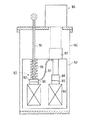
その一例を図6に示す。図示の低温容器は、外側容器である真空容器80と、その内側に配された内側容器である輻射熱シールド層82とを備え、この輻射熱シールド層82の内側に超電導マグネット84が収納されている。冷凍機86は、その中間部に第1冷却端87、下端部に第2冷却端88を有し、その第1冷却端87が上記輻射熱シールド層82に連結されるとともに、第2冷却端88が熱伝導ブロック89を介して超電導マグネット84に連結されている。
【0004】
ところで、上記第2冷却端88は、第1冷却端87よりも冷却温度が低い(第1冷却端87は約80K、第2冷却端88は約20K)反面、常温付近の高温域での冷凍能力が低い(第1冷却端87は約100W、第2冷却端88は約20W)という特性を有している。従って、第2冷却端88のみを用いて超電導マグネット84を冷却しようとすると、当該超電導マグネット84が室温からその目標温度(約4K)にたどりつくまでに多大な時間を要することになる。
【0005】
そこで、図示の装置では、予冷時には被冷却体である超電導マグネット84と第1冷却端87とを熱的に短絡させて予冷速度を上げる一方、予冷が十分進行した時点から超電導マグネット84と第1冷却端87とを切り離して第2冷却端88のみで超電導マグネット84を超低温まで冷却するための熱スイッチ90が設けられている。
【0006】
この熱スイッチ90は、超電導マグネット84の上面に固定される熱伝導体91と、第1冷却端87に伝熱ブスバー93を介して熱的に接続される熱伝導体92とを備え、この熱伝導体92が上下動可能な軸94の下端に固定されるとともに、スプリング95によって下方に付勢されている。そして、予冷時には上記スプリング95の弾発力によって熱伝導体91,92の接触状態が保持され、これら熱伝導体91,92及び伝熱ブスバー93を介して超電導マグネット84と第1冷却端87とが短絡される一方、予冷がある程度進行した時点からは上記軸94を強制的に引き上げて熱伝導体92を熱伝導体91から離間させることにより、超電導マグネット84を第1冷却端87から熱的に切り離すことが可能になっている。
【0007】
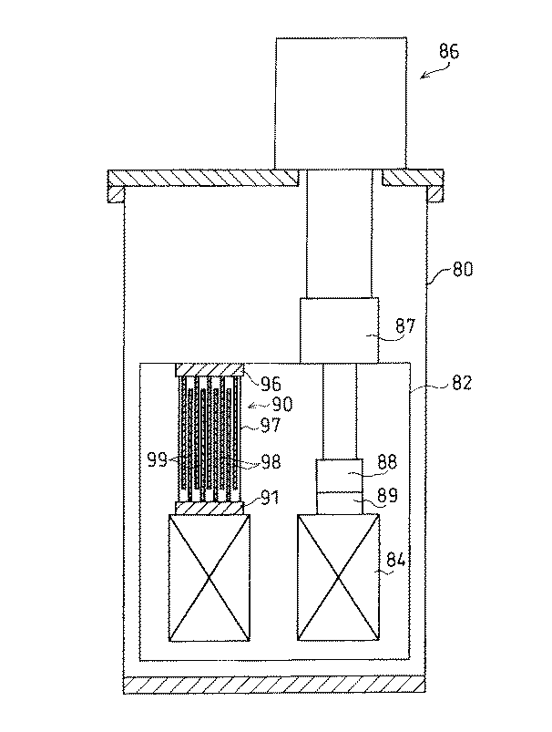
このような熱スイッチ90としては、上記のような機械式のものの他、例えば特開平9−166365号公報に示されるような気体式熱スイッチが知られている。その構造を図7に示す。図示の熱スイッチ90は、超電導マグネット84の上面に固定された熱伝導体91と、輻射熱シールド層82側に固定された熱伝導体96とが筒状の側壁97で連結された容器状をなし、その中には極低温で液化するガス(窒素、アルゴン、ネオン等)が充填されている。容器内では、熱伝導体91から上方に多数枚の伝熱フィン98が延びる一方、熱伝導体96から下方に同じく多数枚の伝熱フィン99が延びており、両伝熱フィン98,99の間に微小すき間が確保されている。
【0008】
この熱スイッチ90によれば、比較的温度の高い予冷初期には、熱スイッチ90内に充満するガスが伝熱媒体となって両伝熱フィン98,99間の伝熱が行われ、超電導マグネット84が熱スイッチ90及び輻射熱シールド層82を介して第1冷却端87に熱的に接続される。その後、予冷が進んで熱スイッチ90内温度が封入ガスの沸点まで降下した時点で、当該ガスが液化することにより、熱スイッチ90内が略真空状態となって伝熱媒体が存在しなくなり、超電導マグネット84と輻射熱シールド層82及び第1冷却端87とが熱的に切り離されることになる。
【0009】
【発明が解決しようとする課題】
上述の従来装置には、次のような解決すべき課題がある。
【0010】
A)機械式熱スイッチ(図6)について
・熱伝動体91,92同士の機械的な面接触によって伝熱を行うので、その伝熱特性は熱伝導体91,92の接触面の状態や熱伝導体91,92の材質に大きく依存する。従って、安定した伝熱特性は得られにくい。
【0011】
・超電導マグネット84を極低温まで予冷するのに必要な熱伝導能力(約9W;温度差にして10K)を確保するには、例えば両熱伝導体91,92が銅で形成されている場合でも、45cm2程度の接触表面積を確保しなければならない。しかも、使用環境が極低温かつ高真空下にあり、その上脱着操作が必要であるため、接触熱伝達を促進するための媒介物(インジウム、グリース、接着剤等)を使用することができず、この媒介物による接触熱伝達性能の向上は図れない。従って、十分な熱伝導能力をもった熱スイッチ90を設置するには多大なスペースが必要になり、容器全体の小型化は困難である。
【0012】
B)気体式熱スイッチ(図7)について
スイッチオンの状態、すなわち、熱スイッチ90内にガスが充満している状態でも、約1W/K程度の熱伝導能力しか得られない。従って、予冷時に例えば90Wの負荷を見込んだとすると、熱スイッチ90の両端には90Kの温度差が発生することになり、十分な熱短絡は望み得ない。一方、スイッチオフの状態では、ガスによる熱伝導はほぼ0Wとなるものの、側壁90を介した固体熱伝導が約0.1W残り、その分の熱侵入を許容してしまうことになる。すなわち、この気体式のものでは、オン時及びオフ時における熱伝導量の比であるオンオフ比が約10と小さく、高いスイッチ性能が得られない不都合がある。
【0013】
本発明は、このような事情に鑑み、コンパクトな構造で、迅速な予冷ができ、かつ予冷後の被冷却体への熱侵入を効果的に阻止できる熱スイッチをもつ冷凍装置を備えた低温容器を提供することを目的とする。
【0014】
【課題を解決するための手段】
上記課題を解決するための手段として、本発明は、外側容器と、この外側容器の内側に設けられ、超電導マグネットを収納する内側容器とを備えた低温容器において、第1冷却端とこの第1冷却端よりも冷凍能力が低くかつ冷凍温度の低い第2冷却端とを有する冷凍機を備え、上記冷凍機の第1冷却端を上記内側容器に熱的に接続し、当該冷凍機の第2冷却端を上記超電導マグネットに熱的に接続して、当該冷凍機の運転により上記内側容器及び上記超電導マグネットがそれぞれ冷却されるように構成するとともに、この冷凍機とは別に、冷媒入口及び冷媒出口を有する冷凍機予冷用の冷媒配管を備え、この冷媒配管の途中に、当該配管内を流れる冷媒と上記第1冷却端との間で熱交換を行わせる第1熱交換部と、この第1熱交換部の下流側の位置で当該配管内を流れる冷媒と上記第2冷却端との間で熱交換を行わせる第2熱交換部とを設けることにより、上記冷凍機の予冷時に上記第1冷却端で発生した寒冷が上記配管内を流れる冷媒を介して上記第2冷却端に伝達されるように構成したものである。
【0015】
この装置において、まず冷凍機の予冷を開始する際には、上記冷媒配管内にその冷媒入口から冷媒出口に向けて冷媒を流すようにすればよい。これにより、第1冷却端で発生した寒冷が第1熱交換部を通じて冷媒に回収され、第2熱交換部を通じて第2冷却端に伝達される。従って、この第2冷却端に接触している被冷却体である超電導マグネットは、第1冷却端及び第2冷却端の双方を用いて迅速に予冷されることになる。しかも、第1熱交換部から第2熱交換部へ積極的に冷媒を流動させることにより、従来の気体式熱スイッチのように冷媒であるガスが容器内で静止しているものに比べ、効率のよい熱伝達ができる。予冷がある程度進行した時点からは、冷媒配管内を排気して冷媒を除去することにより、第1冷却端から第2冷却端への熱侵入を抑えることにより、第2冷却端のみを用いて被冷却体を十分低い温度まで冷却することができる。
【0016】
ここで、上記冷媒入口及び冷媒出口に接続され、当該冷媒入口から第1熱交換部及び第2熱交換部を通って冷媒出口に至る方向に冷媒を循環させる冷媒循環手段を備えれば、冷媒を消費することなく、効率のよい熱伝達ができる。
【0017】
上記冷媒配管は、その設置環境に応じて形状や構造を自由に設定することができる。例えば、上記第1熱交換部(第2熱交換部)を、上記第1冷却端(第2冷却端)と冷媒配管とが接触する状態で当該第1冷却端(第2冷却端)の周囲に冷媒配管を巻回させたものとすることにより、コンパクトな構造としながら効率のよい熱交換を実現できる。
【0018】
また、上記冷媒配管の途中に、上記第1熱交換部へ向かう冷媒と上記第2熱交換部を通過した冷媒との間で熱交換を行わせる向流熱交換部を設ければ、第2熱交換部で冷却に寄与しきれなかった冷媒の寒冷を第1熱交換部へ向かう冷媒に還元することができ、より効率の高い予冷ができる。
【0019】
この場合、上記向流熱交換部を、第1熱交換部へ向かう冷媒が流れる供給配管部と上記第2熱交換部を通過した冷媒が流れる排出配管部のいずれか一方を他方の内側に挿通した二重管で構成すれば、コンパクトな構造としながら効率のよい向流熱交換ができる。
【0020】
さらに、上記二重管部分を上記冷凍機の周囲に巻回することにより、装置全体はよりコンパクト化される。
【0021】
この冷凍装置は、超電導マグネットを収容するクライオスタット(低温容器)の冷却等に好適である。
【0022】
ここで、上記超電導マグネットの内側にサンプルステージが設けられる場合、上記冷媒配管に、その第2熱交換部を通過した冷媒と上記サンプルステージとの間で熱交換を行わせるサンプルステージ熱交換部を付加することにより、当該冷媒配管を利用してサンプルステージの冷却も行うことができる。
【0023】
さらに、上記冷媒配管における第2熱交換部とサンプルステージ熱交換部との間の位置にジュール−トムソン弁を設ければ、このジュール−トムソン弁で冷媒を断熱膨張させることにより、サンプルステージをより低い温度まで冷却することが可能になる。
【0024】
【発明の実施の形態】
本発明の第1の実施の形態を、図1〜図3に基づいて説明する。
【0025】
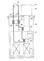
図1に示す低温容器は、外側容器である真空容器10と、その内側に収容される内側容器である輻射熱シールド層12とを備えている。輻射熱シールド層12内には、被冷却体である超電導マグネット14が収納され、これを冷却するための冷凍機16が容器に組み込まれている。
【0026】
この実施の形態では、G−Mサイクル(Gifford-MacMahon cycle)を実行する冷凍機16が使用されている。具体的に、この冷凍機16は、図2に示すような本体ケーシング18と、第1シリンダ20及び第1冷却端22と、これより小径の第2シリンダ24及び第2冷却端26とを備えている。
【0027】
第1シリンダ20内には第1ディスプレーサ28が上下動可能に装填され、第2シリンダ24内には上記第1ディスプレーサ28と一体に上下動する第2ディスプレーサ30が装填されている。第1ディスプレーサ28内及び第2ディスプレーサ30内にはそれぞれ蓄冷材32,34が充填され、各ディスプレーサ28,30の上端にはその内外を連通する連通孔36,38がそれぞれ設けられるとともに、そのすぐ下方の位置にシリンダ20,24の内壁面と接触するシールリング40,42が固定されている。
【0028】
本体ケーシング18内には、両ディスプレーサ28,30を昇降させるクランク44と、第1シリンダ20の上端部に連通するガス給排路46とが設けられ、このガス給排路46が、高圧弁47を介して圧縮機49の吐出口に接続されるとともに、低圧弁48を介して圧縮機49の吸込口に接続されている。
【0029】
この冷凍機16の作動原理は次の通りである。
【0030】
(1) ディスプレーサ28,30が下死点にある時に高圧弁47を開く。すると、冷媒であるヘリウムガスがシリンダ20,24内に流入し、系内に残留しているヘリウムを圧縮していく。これに伴う僅かな発熱は系外へ放出される。
【0031】
(2) ディスプレーサ28,30を上死点へ向かって移動させる。このとき、膨張空間には高圧弁47からの高圧ヘリウムガスが随時補給される。
【0032】
(3) ディスプレーサ28,30が上死点に近づいた時点で高圧弁47を閉じ、その後直ちに低圧弁48を開く。すると、系内の高圧ヘリウムが断熱膨張して圧縮機49内に流入し、系内ガスの内部エネルギー及び温度が低下する。
【0033】
(4) ディスプレーサ28,30が下死点に向かう。その際、(3)で温度低下したヘリウムが蓄冷材32,34を通過しながらこれを冷却する。すなわち、ヘリウムガスの寒冷が蓄冷材32,34に蓄えられる。その後、(1)の行程に戻ると、ヘリウムガスが蓄冷材32,34により熱を奪われながら下部空間に流入し、第1冷却端22及び第2冷却端26を冷却する。
【0034】
以上のサイクルが繰り返されることにより、第1冷却端22及び第2冷却端26の温度は徐々に低下していき、第1冷却端22の温度は約80Kに到達する。この第1冷却端22よりも熱容量の小さい第2冷却端26はさらに温度が下がり、超電導マグネット14の目標温度である約4Kまで到達する。
【0035】
なお、本発明において用いる冷凍機は、上記G−Mサイクルを行うものに限らず、その他のサイクル、例えばスターリングサイクルやソルベーサイクルを行う冷凍機であっても、第1冷却端及び第2冷却端を有するものであれば広く利用が可能である。
【0036】
図1に示すように、上記冷凍機16は、その第1シリンダ20が真空容器10の天壁を上下に貫通する状態で本体ケーシング18が真空容器10の天壁に固定された状態にある。第1冷却端22は、第2シリンダ24が輻射熱シールド層12の天壁を貫通した状態で輻射熱シールド層12の上面に連結、固定されている(すなわち熱的に接続されている)。第2冷却端26は、熱伝導ブロック27を介して超電導マグネット14に連結されている。この熱伝導ブロック27は、例えば銅のように熱伝導率が十分高い材料で形成されており、従って第2冷却端26は実質上超電導マグネット14に熱的に接続された状態となっている。この熱伝導ブロック27については、第2冷却端26及び超電導マグネット14の構造に応じて適宜省略が可能である。
【0037】
さらに、この冷凍装置では、熱スイッチ手段として、冷媒(例えばヘリウムガス)が流通可能な薄肉パイプからなる冷媒配管50を備えている。この冷媒配管50は、両端に冷媒入口51及び冷媒出口52を有し、これらが真空容器10の上方に突出した状態で、中間部が真空容器10内に収納されている。その途中には、管内を流れる冷媒と上記第1冷却端22との熱交換を行わせる第1熱交換部53、及び、管内を流れる冷媒と上記第2冷却端26との熱交換を行わせる第2熱交換部54が設けられるとともに、上記第1熱交換部53へ向かう冷媒と上記第2熱交換部54を通過した冷媒との間で熱交換を行わせる向流熱交換部55が設けられている。
【0038】
上記各熱交換部53〜55はチューブ状であるため、その形状設定の自由度は非常に高い。従って、容器内の構造に応じて自由な形状設定ができるが、中でもコンパクトでかつ熱交換性能の高い構造例を図3に示す。
【0039】
図において、第1熱交換部53は螺旋状をなし、第1冷却端22と接触する状態で当該第1冷却端22の周囲に巻回されている。同様に、第2熱交換部54も螺旋状をなし、第2冷却端26と接触する状態で当該第2冷却端26の周囲に巻回されている。
【0040】
向流熱交換部55は、所謂チューブインチューブ式の熱交換器とされている。すなわち、第1熱交換部53へ向かう冷媒が流れる供給配管部55aが、第2熱交換部54を通過した冷媒が流れる排出配管部55b内に挿通された二重管構造とされている。しかも、この二重管部分が第1シリンダ20の周囲に巻回される螺旋状とすることにより、一層のコンパクト化が図られている。
【0041】
なお、この向流熱交換部55を図示の二重管構造とする場合、その内外関係は逆でもよい。すなわち、供給配管部55aの内側に排出配管部55bを挿通するようにしてもよい。
【0042】
また、冷媒配管50の具体的な材質は問わず、例えばステンレス鋼も適用が可能であるが、少なくとも、熱交換を直接行う部分、すなわち、第1熱交換部53や第2熱交換部54、向流熱交換部55を二重管とする場合の内側管部分は、銅等のように熱伝導率の高い材料で形成することが、より好ましい。
【0043】
上記冷媒入口51及び冷媒出口52には、循環ポンプ(冷媒循環手段)60の吐出口及び吸込口がそれぞれ接続可能とされている。この実施の形態では、冷媒入口51及び冷媒出口52にそれぞれセルフシールカップリングが設けられている。従って、これら出入口51,52に対して循環ポンプ60が着脱可能に接続されるとともに、非接続状態では自動的に出入口51,52が塞がれ、シールされるようになっている。このセルフシールカップリングについては、例えば下水道で用いられているボール式バルブを備えたものなど、種々のものが適用可能である。また、このようなセルフシールカップリングを用いず、別の手段でポンプ非接続時の出入口51,52のシールを行うようにしてもよい。
【0044】
次に、この装置の作用を説明する。
【0045】
まず、室温状態から予冷を開始するにあたっては、冷媒入口51,52に循環ポンプ60の吐出口及び吸込口をそれぞれ接続し、循環ポンプ60を作動させて、冷媒入口51→向流熱交換部55の供給配管部55a→第1熱交換部53→第2熱交換部54→交流熱交換部55の排出配管部55b→冷媒出口52の順に冷媒を循環させる。この状態で冷凍機16を作動させると、第1冷却端22から出力される寒冷が第1熱交換部53から第2熱交換部54へ流れる冷媒によって第2出力端26に伝えられることにより、双方の冷却端22,26の冷凍能力を使って超電導マグネット14の予冷が迅速に進められる。さらに、第2熱交換部54で第2出力端26へ排出しきれなかった余剰寒冷は、向流熱交換部55で排出配管部55bから供給配管部55aに還元されるため、これにより冷凍効率が高められる。
【0046】
予冷が進み、超電導マグネット14の温度が第1冷却端22の到達温度以下の温度となった時点で、循環ポンプ60の吐出口と冷媒入口51との接続のみを切離し、冷媒入口51をシールする。この時点から循環ポンプ60は真空ポンプとなり、冷媒配管50内の冷媒を排気して冷媒配管50内を減圧する。これにより、第1熱交換部53から第2熱交換部54へ寒冷を伝える熱媒体が存在しなくなり、第1冷却端22と第2冷却端26とが熱的に切り離される。その後は、第2冷却端26のみで超電導マグネット14の冷却を行うことにより、この超電導マグネット14の温度を目標温度まで降下させることができる。超電導マグネット14が超電導状態となり、通電可能な状態となったら、循環ポンプ60の吸込口と冷媒出口52との接続も切離すようにすればよい。
【0047】
次の表1は、図1にかかる本発明装置、図6にかかる機械式熱スイッチを備えた従来装置、図7にかかる気体式熱スイッチを備えた従来装置の各装置について、スイッチオン時の熱伝導特性、スイッチオフ時の熱伝導特性、両特性の比であるオンオフ比、及び上から見た熱スイッチの占有面積(冷凍機投影面積を除く)を示したものである。
【0048】
【表1】
この表に示されるように、図1に示した本発明装置では、オン特性に優れており、第1冷却端22で発生した寒冷を高い効率で超電導マグネット14の冷却に寄与させることができる。これは、従前の気体式熱スイッチと異なり、冷媒配管50内で冷媒を第1熱交換部53から第2熱交換部54へ流動させて積極的に熱移動させていることに大きな要因があると考えられる。一方、オフ特性についてみると、本発明装置では、冷媒配管50内を排気した状態での第1冷却端22から第2冷却端26への熱侵入がほぼ0に近く、機械式スイッチと比べても遜色のないものとなっている。これは、気体式熱スイッチと比べて冷媒配管50の断面積がはるかに小さく、しかも冷媒配管50を通じての熱伝導がほとんどないためであると考えられる。このため、本発明装置のオンオフ比は非常に高いものとなっており、本発明にかかる冷媒配管50が熱スイッチとして非常に優れたものであることが理解できる。
【0050】
一方、占有面積について着目すると、上記実施形態にかかる装置では、図3のように各熱交換部53〜55を冷凍機16の周囲に巻回した螺旋状としているので、その占有面積はほとんど0に等しく、きわめてコンパクトな構造となっている。また、上記のような螺旋状でないとしても、冷媒配管50の形状設定の自由度は高いため、容器内構造に応じて自由に冷媒配管50を配索することが可能であり、容器全体のコンパクト化に寄与できることに疑いはない。
【0051】
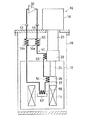
本発明の第2の実施の形態を図4に示す。上記のように被冷却体が超電導マグネット14である場合、その内側に図4に示すようなサンプル載置用のサンプルステージ62を設け、低温下での各種サンプルの物理特性を測定する機能を付加することがある。そこで、この実施の形態では、冷媒配管50の第2熱交換部54の下流側にサンプルステージ熱交換部56を設け、第2熱交換部54から排出された冷媒とサンプルステージ62との間で熱交換を行わせるようにしている。
【0052】
この構成によれば、冷媒配管50を積極的に利用してサンプルステージ62の冷却も行うことができる。また、サンプルステージ62に例えば電熱ヒータを設け、この電熱ヒータの電熱量と循環する冷媒(ヘリウムガス)流量とのバランスを調節することにより、サンプルステージ62を所望の温度(>第2冷却端温度)にすることが可能であり、広範囲の温度域にわたる物性測定が可能になる。
【0053】
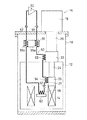
さらに、第3の実施の形態として図5に示すように、第2熱交換部54とサンプルステージ熱交換部56との間にジュール−トムソン弁57を設け、このJT弁57でヘリウムガスを断熱膨張させてからサンプルステージ熱交換部56に送りこむことにより、サンプルステージ62をヘリウム沸点(約4.2K)よりも低い温度まで冷却することができ、測定温度域をさらに拡大することが可能となる。
【0054】
なお、本発明は、その他、例として次のような形態をとることも可能である。
【0055】
(1) 前記実施形態では、冷媒出入口51,52と循環ポンプ60とを着脱可能に接続できるようにしているが、例えば第2及び第3の実施の形態のように予冷完了後も冷媒循環を行って冷却動作を行うような場合には、循環ポンプ60を冷媒配管50に一体につないでしまっても構わない。
【0056】
(2) 本発明において、各熱交換部の構造は適宜設定が可能である。例えば、第1冷却端22や第2冷却端26、サンプルステージ62の表面に、冷媒配管50の途中部分を蛇行させながら配索するようにしてもよい。また、向流熱交換部55においては、例えば供給配管部55aと排出配管部55bとを平行に並べて相互接触させるような構造としてもよい。
【0057】
【発明の効果】
以上のように本発明は、第1冷却端及び第2冷却端を有する冷凍機を用いた冷凍装置において、冷媒配管を流れる冷媒と第1冷却端との間で熱交換を行わせるとともに、その下流側の位置で上記冷媒配管内を流れる冷媒と上記第2冷却端との間で熱交換を行わせるようにしたものであるので、コンパクトな構造でありながら、予冷時には流動冷媒を用いて第1冷却端と第2冷却端との熱伝達を効率よく行わせて迅速な冷却を行い、予冷完了時には冷媒配管内の冷媒を除去することによって第1冷却端から第2冷却端への熱侵入を十分に抑制することができる効果がある。
【図面の簡単な説明】
【図1】 本発明の第1の実施の形態にかかる冷凍装置を備えた低温容器の断面図である。
【図2】 上記冷凍装置に用いられる冷凍機の断面図である。
【図3】 上記冷凍装置における各熱交換部の構造を示す一部断面斜視図である。
【図4】 本発明の第2の実施の形態にかかる冷凍装置を備えた低温容器の断面図である。
【図5】 本発明の第3の実施の形態にかかる冷凍装置を備えた低温容器の断面図である。
【図6】 従来の冷凍装置及び当該装置を備えた低温容器の断面図である。
【図7】 従来の冷凍装置及び当該装置を備えた低温容器の断面図である。
【符号の説明】
10 真空容器
12 輻射熱シールド層
14 超電導マグネット(被冷却体)
16 冷凍機
22 第1冷却端
26 第2冷却端
50 冷媒配管
51 冷媒入口
52 冷媒出口
53 第1熱交換部
54 第2熱交換部
55 向流熱交換部
55a 供給配管部
55b 排出配管部
56 サンプルステージ熱交換部
57 ジュール−トムソン弁
60 循環ポンプ[0001]
BACKGROUND OF THE INVENTION
The present invention relates to a cryogenic container equipped with a refrigeration apparatus using a refrigerator having multiple stages of cooling ends having different refrigeration capacities and cooling temperatures.
[0002]
[Prior art]
In recent years, as a means for holding a cooled object such as a superconducting magnet in a cryogenic state, the cooled object is housed in a cryogenic container, and a refrigerator having a plurality of stages of cooling ends having different refrigeration capacities and cooling temperatures. What has been actively cooled has been developed.
[0003]
An example is shown in FIG. The illustrated cryogenic container includes a
[0004]
By the way, the cooling temperature of the
[0005]
Therefore, in the illustrated apparatus, during the precooling, the
[0006]
The
[0007]
As such a
[0008]
According to the
[0009]
[Problems to be solved by the invention]
The above-described conventional apparatus has the following problems to be solved.
[0010]
A) Mechanical heat switch (FIG. 6)-Since heat transfer is performed by mechanical surface contact between the
[0011]
In order to ensure the heat conduction capacity (about 9 W; temperature difference 10 K) necessary for precooling the
[0012]
B) Gas type thermal switch (FIG. 7) Even in a switch-on state, that is, in a state where the gas is filled in the
[0013]
In view of such circumstances, a compact structure can quickly precooling and cryogenic vessel equipped with a refrigeration system having a heat switch which can effectively prevent heat penetration into the object to be cooled after precooling The purpose is to provide.
[0014]
[Means for Solving the Problems]
As means for solving the above-mentioned problems, the present invention provides a first cooling end and a first cooling end in a low-temperature container including an outer container and an inner container provided inside the outer container and containing a superconducting magnet . A refrigerating machine having a refrigerating capacity lower than the cooling end and a second refrigerating end having a low refrigerating temperature , thermally connecting the first cooling end of the refrigerating machine to the inner container, The cooling end is thermally connected to the superconducting magnet so that the inner container and the superconducting magnet are cooled by the operation of the refrigerator, and the refrigerant inlet and the refrigerant outlet are separated from the refrigerator. It includes a refrigerant pipe for refrigerating machine pre-cooling with, in the middle of the refrigerant pipe, a first heat exchanger to perform heat exchange between the refrigerant and the first cold end flowing in the pipe, the first Downstream side of heat exchanger The Rukoto provided a second heat exchanger to perform heat exchange between the refrigerant and the second cold end flowing in the pipe at the position occurred in the first cold end when the pre-cooling of the refrigerator cold Is transmitted to the second cooling end via the refrigerant flowing in the pipe .
[0015]
In this apparatus, when pre-cooling of the refrigerator is first started, the refrigerant may flow into the refrigerant pipe from the refrigerant inlet toward the refrigerant outlet. As a result, the cold generated at the first cooling end is recovered to the refrigerant through the first heat exchange unit and transmitted to the second cooling end through the second heat exchange unit. Therefore, the superconducting magnet , which is the object to be cooled that is in contact with the second cooling end, is quickly pre-cooled using both the first cooling end and the second cooling end. In addition, by actively flowing the refrigerant from the first heat exchanging part to the second heat exchanging part, the refrigerant gas is more efficient than the conventional gas type heat switch in which the gas as the refrigerant is stationary in the container. Good heat transfer. From the point of time when the pre-cooling has progressed to some extent, exhausting the refrigerant pipe and removing the refrigerant prevents the heat from entering from the first cooling end to the second cooling end, so that only the second cooling end is used. The cooling body can be cooled to a sufficiently low temperature.
[0016]
Here, if the refrigerant circulation means connected to the refrigerant inlet and the refrigerant outlet and circulates the refrigerant in a direction from the refrigerant inlet to the refrigerant outlet through the first heat exchange unit and the second heat exchange unit, the refrigerant is provided. Efficient heat transfer is possible without consuming energy.
[0017]
The refrigerant pipe can be freely set in shape and structure according to its installation environment. For example, the first heat exchange part (second heat exchange part) is surrounded by the first cooling end (second cooling end) in a state where the first cooling end (second cooling end) and the refrigerant pipe are in contact with each other. By having the refrigerant pipe wound around, efficient heat exchange can be realized while having a compact structure.
[0018]
In addition, if a counter-current heat exchanging section is provided in the middle of the refrigerant pipe to perform heat exchange between the refrigerant going to the first heat exchanging section and the refrigerant passing through the second heat exchanging section, the second The cooling of the refrigerant that has not been able to contribute to cooling in the heat exchange part can be reduced to the refrigerant that goes to the first heat exchange part, and more efficient pre-cooling can be performed.
[0019]
In this case, either the supply pipe part through which the refrigerant heading to the first heat exchange part flows or the discharge pipe part through which the refrigerant that has passed through the second heat exchange part is inserted inside the other counter current heat exchange part. If the double pipe is used, efficient counter-current heat exchange can be performed with a compact structure.
[0020]
Furthermore, the whole apparatus is made more compact by winding the double pipe portion around the refrigerator.
[0021]
The refrigeration apparatus is suitable for cooling or the like of the cryostat (cryostat) for accommodating the superconducting magnet.
[0022]
Here, when a sample stage is provided inside the superconducting magnet, a sample stage heat exchanging section that causes the refrigerant pipe to perform heat exchange between the refrigerant that has passed through the second heat exchanging section and the sample stage is provided. By adding, the sample stage can also be cooled using the refrigerant pipe.
[0023]
Further, if a Joule-Thomson valve is provided at a position between the second heat exchange section and the sample stage heat exchange section in the refrigerant pipe, the sample stage is further expanded by adiabatically expanding the refrigerant with the Joule-Thomson valve. It becomes possible to cool to a low temperature.
[0024]
DETAILED DESCRIPTION OF THE INVENTION
A first embodiment of the present invention will be described with reference to FIGS.
[0025]
The cryogenic container shown in FIG. 1 includes a
[0026]
In this embodiment, a
[0027]
A
[0028]
A crank 44 for raising and lowering both
[0029]
The operating principle of the
[0030]
(1) The
[0031]
(2) The
[0032]
(3) The
[0033]
(4) The
[0034]
By repeating the above cycle, the temperature of the first cooling
[0035]
In addition, the refrigerator used in the present invention is not limited to the one that performs the GM cycle, but may be a refrigerator that performs other cycles, for example, a Stirling cycle or a Solvay cycle. If it has, it can be widely used.
[0036]
As shown in FIG. 1, the
[0037]
Further, this refrigeration apparatus includes a
[0038]
Since each said heat exchange part 53-55 is tube shape, the freedom degree of the shape setting is very high. Therefore, although a free shape can be set according to the structure in the container, FIG. 3 shows an example of a structure that is compact and has high heat exchange performance.
[0039]
In the figure, the first
[0040]
The
[0041]
In addition, when this counterflow heat-
[0042]
In addition, regardless of the specific material of the
[0043]
A discharge port and a suction port of a circulation pump (refrigerant circulation means) 60 can be connected to the
[0044]
Next, the operation of this apparatus will be described.
[0045]
First, when pre-cooling is started from the room temperature state, the discharge port and the suction port of the
[0046]
When pre-cooling progresses and the temperature of the
[0047]
Table 1 below shows the device of the present invention according to FIG. 1, the conventional device with the mechanical thermal switch according to FIG. 6, and the conventional device with the gas thermal switch according to FIG. The heat conduction characteristics, the heat conduction characteristics when the switch is turned off, the on / off ratio that is the ratio of the two characteristics, and the area occupied by the heat switch as seen from above (excluding the projected area of the refrigerator) are shown.
[0048]
[Table 1]
As shown in this table, the device of the present invention shown in FIG. 1 has excellent on-characteristics, and the cold generated at the first cooling
[0050]
On the other hand, paying attention to the occupied area, the apparatus according to the above embodiment has a spiral shape in which the
[0051]
A second embodiment of the present invention is shown in FIG. When the object to be cooled is the
[0052]
According to this configuration, the
[0053]
Furthermore, as shown in FIG. 5 as a third embodiment, a Joule-
[0054]
In addition, the present invention can also take the following forms as examples.
[0055]
(1) In the above-described embodiment, the refrigerant inlet /
[0056]
(2) In the present invention, the structure of each heat exchange part can be set as appropriate. For example, the first cooling
[0057]
【The invention's effect】
As described above, in the refrigeration apparatus using the refrigerator having the first cooling end and the second cooling end, the present invention allows heat exchange between the refrigerant flowing through the refrigerant pipe and the first cooling end, and Since heat is exchanged between the refrigerant flowing in the refrigerant pipe at the downstream position and the second cooling end, a fluid refrigerant is used during precooling while having a compact structure. The heat transfer from the first cooling end to the second cooling end is performed by efficiently performing heat transfer between the first cooling end and the second cooling end, and by quickly removing the refrigerant in the refrigerant pipe when the pre-cooling is completed. There is an effect that can be sufficiently suppressed.
[Brief description of the drawings]
FIG. 1 is a cross-sectional view of a cryogenic container equipped with a refrigeration apparatus according to a first embodiment of the present invention.
FIG. 2 is a sectional view of a refrigerator used in the refrigeration apparatus.
FIG. 3 is a partial cross-sectional perspective view showing the structure of each heat exchange unit in the refrigeration apparatus.
FIG. 4 is a cross-sectional view of a cryogenic container equipped with a refrigeration apparatus according to a second embodiment of the present invention.
FIG. 5 is a cross-sectional view of a cryogenic container equipped with a refrigeration apparatus according to a third embodiment of the present invention.
FIG. 6 is a cross-sectional view of a conventional refrigeration apparatus and a cryogenic container equipped with the apparatus.
FIG. 7 is a cross-sectional view of a conventional refrigeration apparatus and a cryogenic container equipped with the apparatus.
[Explanation of symbols]
10
16
Claims (9)
Priority Applications (1)
| Application Number | Priority Date | Filing Date | Title |
|---|---|---|---|
| JP22732498A JP3673410B2 (en) | 1998-08-11 | 1998-08-11 | Cryogenic container |
Applications Claiming Priority (1)
| Application Number | Priority Date | Filing Date | Title |
|---|---|---|---|
| JP22732498A JP3673410B2 (en) | 1998-08-11 | 1998-08-11 | Cryogenic container |
Publications (2)
| Publication Number | Publication Date |
|---|---|
| JP2000055492A JP2000055492A (en) | 2000-02-25 |
| JP3673410B2 true JP3673410B2 (en) | 2005-07-20 |
Family
ID=16859035
Family Applications (1)
| Application Number | Title | Priority Date | Filing Date |
|---|---|---|---|
| JP22732498A Expired - Lifetime JP3673410B2 (en) | 1998-08-11 | 1998-08-11 | Cryogenic container |
Country Status (1)
| Country | Link |
|---|---|
| JP (1) | JP3673410B2 (en) |
Cited By (3)
| Publication number | Priority date | Publication date | Assignee | Title |
|---|---|---|---|---|
| JP2011141074A (en) * | 2010-01-06 | 2011-07-21 | Toshiba Corp | Cryogenic refrigerator |
| JP2016034509A (en) * | 2009-12-28 | 2016-03-17 | コーニンクレッカ フィリップス エヌ ヴェKoninklijke Philips N.V. | Tubular thermal switch for refrigerant-free magnet |
| CN109712783A (en) * | 2019-01-15 | 2019-05-03 | 娄莉 | A kind of MRI cooling device |
Families Citing this family (8)
| Publication number | Priority date | Publication date | Assignee | Title |
|---|---|---|---|---|
| CN100440750C (en) | 2001-11-20 | 2008-12-03 | 高通股份有限公司 | Reverse link power controlled repeater |
| US9118380B2 (en) | 2004-04-05 | 2015-08-25 | Qualcomm Incorporated | Repeater with positioning capabilities |
| RU2355129C2 (en) | 2004-04-05 | 2009-05-10 | Квэлкомм Инкорпорейтед | Retransmitter reporting detected neighbours |
| JP5622485B2 (en) * | 2010-08-20 | 2014-11-12 | 株式会社サーマルブロック | Combined cryogenic refrigerator |
| GB201212800D0 (en) * | 2012-07-19 | 2012-09-05 | Oxford Instr Nanotechnology Tools Ltd | Cryogenic cooloing apparatus and method |
| JP7034877B2 (en) * | 2018-10-02 | 2022-03-14 | 株式会社東芝 | Very low temperature cooling device |
| JP2020076519A (en) * | 2018-11-06 | 2020-05-21 | 大陽日酸株式会社 | Dilution |
| JP6945771B1 (en) * | 2020-03-12 | 2021-10-06 | 三菱電機株式会社 | Superconducting magnet |
-
1998
- 1998-08-11 JP JP22732498A patent/JP3673410B2/en not_active Expired - Lifetime
Cited By (3)
| Publication number | Priority date | Publication date | Assignee | Title |
|---|---|---|---|---|
| JP2016034509A (en) * | 2009-12-28 | 2016-03-17 | コーニンクレッカ フィリップス エヌ ヴェKoninklijke Philips N.V. | Tubular thermal switch for refrigerant-free magnet |
| JP2011141074A (en) * | 2010-01-06 | 2011-07-21 | Toshiba Corp | Cryogenic refrigerator |
| CN109712783A (en) * | 2019-01-15 | 2019-05-03 | 娄莉 | A kind of MRI cooling device |
Also Published As
| Publication number | Publication date |
|---|---|
| JP2000055492A (en) | 2000-02-25 |
Similar Documents
| Publication | Publication Date | Title |
|---|---|---|
| JP3673410B2 (en) | Cryogenic container | |
| JP2013522574A (en) | Method and apparatus for controlling temperature in a cryogenic cryostat using stationary and flowing gases | |
| CN110617650B (en) | Cryogenic cooling system | |
| JPS5880474A (en) | Cryogenic cooling device | |
| CN103047788B (en) | J-T throttling refrigeration circulating system driven by low-temperature linear compressor | |
| JP4595121B2 (en) | Cryogenic refrigerator using mechanical refrigerator and Joule Thomson expansion | |
| JPH08222429A (en) | Device for cooling to extremely low temperature | |
| Hirai et al. | Development of a turbine cryocooler for high temperature superconductor applications | |
| KR100310819B1 (en) | Cryogenic Chiller with Reverse Brayton Cycle | |
| JPS63302259A (en) | Cryogenic generator | |
| CN112325498B (en) | Dilution refrigeration system and method | |
| Uhlig | Cryogen-free dilution refrigerators | |
| Crunkleton | A new configuration for small-capacity liquid-helium-temperature cryocoolers | |
| JPH10246524A (en) | Freezing device | |
| JPH11173697A (en) | Cold storage refrigerating machine | |
| Gao | IGC-APD advanced two-stage pulse tube cryocoolers | |
| JPH0452468A (en) | Cryogenic refrigerator | |
| JPS608674A (en) | Cryogenic refrigerator | |
| Duband et al. | Socool: A 300 K-0.3 K pulse tube/sorption cooler | |
| JPH10177914A (en) | Superdonducting magnet system with refrigerater | |
| CN115615029A (en) | sub-Kelvin temperature zone refrigerating mechanism | |
| JP2707624B2 (en) | Cryogenic refrigeration equipment | |
| JPH0349019B2 (en) | ||
| JPH11230629A (en) | Stirling cooling and heating device | |
| JPH10306951A (en) | Refrigerating apparatus |
Legal Events
| Date | Code | Title | Description |
|---|---|---|---|
| A131 | Notification of reasons for refusal |
Free format text: JAPANESE INTERMEDIATE CODE: A131 Effective date: 20041130 |
|
| A521 | Written amendment |
Free format text: JAPANESE INTERMEDIATE CODE: A523 Effective date: 20050127 |
|
| TRDD | Decision of grant or rejection written | ||
| A01 | Written decision to grant a patent or to grant a registration (utility model) |
Free format text: JAPANESE INTERMEDIATE CODE: A01 Effective date: 20050419 |
|
| A61 | First payment of annual fees (during grant procedure) |
Free format text: JAPANESE INTERMEDIATE CODE: A61 Effective date: 20050422 |
|
| R150 | Certificate of patent or registration of utility model |
Free format text: JAPANESE INTERMEDIATE CODE: R150 |
|
| FPAY | Renewal fee payment (event date is renewal date of database) |
Free format text: PAYMENT UNTIL: 20080428 Year of fee payment: 3 |
|
| FPAY | Renewal fee payment (event date is renewal date of database) |
Free format text: PAYMENT UNTIL: 20090428 Year of fee payment: 4 |
|
| FPAY | Renewal fee payment (event date is renewal date of database) |
Free format text: PAYMENT UNTIL: 20100428 Year of fee payment: 5 |
|
| FPAY | Renewal fee payment (event date is renewal date of database) |
Free format text: PAYMENT UNTIL: 20100428 Year of fee payment: 5 |
|
| FPAY | Renewal fee payment (event date is renewal date of database) |
Free format text: PAYMENT UNTIL: 20110428 Year of fee payment: 6 |
|
| FPAY | Renewal fee payment (event date is renewal date of database) |
Free format text: PAYMENT UNTIL: 20120428 Year of fee payment: 7 |
|
| FPAY | Renewal fee payment (event date is renewal date of database) |
Free format text: PAYMENT UNTIL: 20130428 Year of fee payment: 8 |
|
| FPAY | Renewal fee payment (event date is renewal date of database) |
Free format text: PAYMENT UNTIL: 20130428 Year of fee payment: 8 |
|
| FPAY | Renewal fee payment (event date is renewal date of database) |
Free format text: PAYMENT UNTIL: 20140428 Year of fee payment: 9 |
|
| EXPY | Cancellation because of completion of term |