JP3670583B2 - Method and system for detecting signal loss in wavelength division multiplexing systems - Google Patents
Method and system for detecting signal loss in wavelength division multiplexing systems Download PDFInfo
- Publication number
- JP3670583B2 JP3670583B2 JP2000571589A JP2000571589A JP3670583B2 JP 3670583 B2 JP3670583 B2 JP 3670583B2 JP 2000571589 A JP2000571589 A JP 2000571589A JP 2000571589 A JP2000571589 A JP 2000571589A JP 3670583 B2 JP3670583 B2 JP 3670583B2
- Authority
- JP
- Japan
- Prior art keywords
- fiber
- amplifier
- wavelength
- detecting
- marker
- Prior art date
- Legal status (The legal status is an assumption and is not a legal conclusion. Google has not performed a legal analysis and makes no representation as to the accuracy of the status listed.)
- Expired - Fee Related
Links
Images


Classifications
-
- H—ELECTRICITY
- H04—ELECTRIC COMMUNICATION TECHNIQUE
- H04B—TRANSMISSION
- H04B10/00—Transmission systems employing electromagnetic waves other than radio-waves, e.g. infrared, visible or ultraviolet light, or employing corpuscular radiation, e.g. quantum communication
- H04B10/07—Arrangements for monitoring or testing transmission systems; Arrangements for fault measurement of transmission systems
-
- H—ELECTRICITY
- H04—ELECTRIC COMMUNICATION TECHNIQUE
- H04B—TRANSMISSION
- H04B10/00—Transmission systems employing electromagnetic waves other than radio-waves, e.g. infrared, visible or ultraviolet light, or employing corpuscular radiation, e.g. quantum communication
- H04B10/29—Repeaters
- H04B10/291—Repeaters in which processing or amplification is carried out without conversion of the main signal from optical form
- H04B10/293—Signal power control
- H04B10/294—Signal power control in a multiwavelength system, e.g. gain equalisation
- H04B10/296—Transient power control, e.g. due to channel add/drop or rapid fluctuations in the input power
-
- H—ELECTRICITY
- H04—ELECTRIC COMMUNICATION TECHNIQUE
- H04B—TRANSMISSION
- H04B10/00—Transmission systems employing electromagnetic waves other than radio-waves, e.g. infrared, visible or ultraviolet light, or employing corpuscular radiation, e.g. quantum communication
- H04B10/03—Arrangements for fault recovery
- H04B10/032—Arrangements for fault recovery using working and protection systems
-
- H—ELECTRICITY
- H04—ELECTRIC COMMUNICATION TECHNIQUE
- H04B—TRANSMISSION
- H04B10/00—Transmission systems employing electromagnetic waves other than radio-waves, e.g. infrared, visible or ultraviolet light, or employing corpuscular radiation, e.g. quantum communication
- H04B10/07—Arrangements for monitoring or testing transmission systems; Arrangements for fault measurement of transmission systems
- H04B10/075—Arrangements for monitoring or testing transmission systems; Arrangements for fault measurement of transmission systems using an in-service signal
- H04B10/077—Arrangements for monitoring or testing transmission systems; Arrangements for fault measurement of transmission systems using an in-service signal using a supervisory or additional signal
- H04B10/0771—Fault location on the transmission path
-
- H—ELECTRICITY
- H04—ELECTRIC COMMUNICATION TECHNIQUE
- H04B—TRANSMISSION
- H04B10/00—Transmission systems employing electromagnetic waves other than radio-waves, e.g. infrared, visible or ultraviolet light, or employing corpuscular radiation, e.g. quantum communication
- H04B10/07—Arrangements for monitoring or testing transmission systems; Arrangements for fault measurement of transmission systems
- H04B10/075—Arrangements for monitoring or testing transmission systems; Arrangements for fault measurement of transmission systems using an in-service signal
- H04B10/079—Arrangements for monitoring or testing transmission systems; Arrangements for fault measurement of transmission systems using an in-service signal using measurements of the data signal
- H04B10/0791—Fault location on the transmission path
-
- H—ELECTRICITY
- H04—ELECTRIC COMMUNICATION TECHNIQUE
- H04B—TRANSMISSION
- H04B10/00—Transmission systems employing electromagnetic waves other than radio-waves, e.g. infrared, visible or ultraviolet light, or employing corpuscular radiation, e.g. quantum communication
- H04B10/25—Arrangements specific to fibre transmission
- H04B10/2581—Multimode transmission
-
- H—ELECTRICITY
- H04—ELECTRIC COMMUNICATION TECHNIQUE
- H04J—MULTIPLEX COMMUNICATION
- H04J14/00—Optical multiplex systems
- H04J14/02—Wavelength-division multiplex systems
- H04J14/0278—WDM optical network architectures
- H04J14/0279—WDM point-to-point architectures
-
- H—ELECTRICITY
- H04—ELECTRIC COMMUNICATION TECHNIQUE
- H04J—MULTIPLEX COMMUNICATION
- H04J14/00—Optical multiplex systems
- H04J14/02—Wavelength-division multiplex systems
- H04J14/0278—WDM optical network architectures
- H04J14/0283—WDM ring architectures
-
- H—ELECTRICITY
- H04—ELECTRIC COMMUNICATION TECHNIQUE
- H04J—MULTIPLEX COMMUNICATION
- H04J14/00—Optical multiplex systems
- H04J14/02—Wavelength-division multiplex systems
- H04J14/0287—Protection in WDM systems
- H04J14/0289—Optical multiplex section protection
- H04J14/0291—Shared protection at the optical multiplex section (1:1, n:m)
-
- H—ELECTRICITY
- H04—ELECTRIC COMMUNICATION TECHNIQUE
- H04B—TRANSMISSION
- H04B2210/00—Indexing scheme relating to optical transmission systems
- H04B2210/07—Monitoring an optical transmission system using a supervisory signal
- H04B2210/078—Monitoring an optical transmission system using a supervisory signal using a separate wavelength
Description
【0001】
(発明の分野)
本発明は、波長分割多重(WDM)システムに関し、特に、WDMシステムにおける障害検出に関する。
【0002】
(発明の背景)
WDM技術は、通信ネットワークにおけるファイバの消耗について、新しくファイバを実装する必要なく、ネットワークのデータ処理量を増大することによって、コスト効果の高い解決法を提供してきた。WDMシステムでは、いくつかの入力信号のそれぞれは、WDMノードまたはネットワーク要素に入り、通常1550ナノメートル(nm)の帯域で割り当てられるか、または特定の波長に変換される。波長変換後、それぞれの個々の信号波長またはチャネルは、波長分割多重方式によって多重化され、同じファイバ上に送信される。WDM技術がネットワーク解決法として真に実行可能であるために、WDMシステムは、また、任意のネットワークで生じる障害に耐えることができなければならない。ネットワーク存続の問題は、WDMシステムが単一ファイバ上で転送するマルチギガビットのデータなど大量の消費者データを考慮すると、ファイバの損失は破局的で出費がかさむことになり得るので、WDMシステムではさらに重要性を帯びることになる。
【0003】
WDMネットワークの存続に関する懸念に応答して、自己回復WDMリングおよびポイントツーポイント多様保護体系(point−to−point diverse protection architectures)が提案されてきた。自己回復リングは、物理的リングトポロジのノードを帯域幅共有および自己回復能力と接続して、ネットワークの欠陥を克服するネットワーク体系である。これを記述するために、リングの各ノードは、ファイバを介して他のノードに接続されている。ファイバ切断またはノードの欠陥など他の障害が生じる場合、リングは自動的に予備(standby)ファイバにスイッチ(switches)し、ある場合には予備(standby)電子機器にスイッチする。同様に、ポイントツーポイント多様保護システムは、自動的に消費者データを異なる経路に沿って経路指定されている予備ファイバにスイッチすることによって、ファイバケーブルの切断からネットワークを保護する。どちらの場合でも、自動的な保護スイッチングは、光学的に、すなわち受信光信号を予備ファイバにスイッチすることによって、または電気的に、すなわち受信光信号の電気的な表示をスイッチすることによって実施することが可能である。WDMネットワークの自動保護スイッチングは、純粋な同期式光ネットワーク(SONET)保護と比較して、かなりコストを削減することを保証する。しかし、自動保護スイッチングをWDMシステムで使用することができるようになる前に、いくつかの基本的な問題に取り組まなければならない。
【0004】
WDMシステムに対する1つのそのような基本的な問題は、光学的に増幅されたリンクで、ファイバ切断を検出することである。ファイバ切断または信号損失の検出は、通常ノード間のリンクはエルビウムドープファイバ増幅器(EDFA)によって光学的に増幅されているので、WDMシステムでは難しい問題であることが判明している。一般に、多重化後およびネットワークファイバ設備またはリンク上への送信前に、各WDMノードで、信号はEDFAによって増幅されている。同様に、受信後、各WDMノードで信号は再び他のEDFAによって増幅され、その後デマルチプレックスされる。送信器と受信器の距離に応じて、1つまたはいくつかの追加のEDFAを、ファイバ経路に沿って、特定の点に配置することも可能である。ファイバ切断と光学モニタまたは受信器の距離および増幅器の数が増大するにつれ、光経路の各EDFAについて、EDFAからの増幅自然放出(amplified spontaneous emission)が増大する。特に、飽和EDFAに光入力信号が存在しないとき、増幅自然放出は、いくつかのEDFAを経た後十分に増大する可能性があり、ファイバ切断が検出されないことがあり得る。実際、増幅自然放出のために、合計の光パワーの測定またはスペクトルバンド内の光パワーの測定でさえ、あるファイバ切断を測定するには不十分である。
【0005】
合計の光パワーの検出は、EDFAに対するファイバ切断の位置および検出の閾値に応じて、あるファイバ切断を検出できないことがある。いくつかのファイバリンクまたはスパン上では、その範囲を超えてノードまたはネットワーク要素にEDFAはないが、他の上では、複数のEDFAが存在することが可能である。図1は、WDMリングにおける従来の作動ファイバ/保護ファイバの対を表し、保護スイッチ121と122を有するネットワークアドドロップ要素(add−drop elements)120を含む。特に、図1に示したように、リンク110上には、2つのアドドロップ要素120間の反時計回りと時計回りの両方向に、4つのEDFA199がある(ここで、図1はリングを示しているが、この議論はポイントツーポイント体系にも関係することに留意されたい)。サブリンク111上で生じるファイバ切断は、モニタ点150で合計光パワーがゼロになるので、モニタ点1501で容易に検出することができる。しかし、サブリンク112、113、114、および115で生じるような、より離れたファイバ切断に対し、インタリーブしているEDFA199によって与えられる増幅自然放出は、モニタ点1501に光パワーをもたらす。
【0006】
インタリーブしているEDFA199の数に関して、モニタ点1501で検出したパワーの間の関係を、図2に示す。図2は、ファイバ切断に関する問題を示す波長領域のシミュレーションである。シミュレーションは、特定のEDFAの特徴と間隔を仮定している。他のEDFA設計に対する結果は、定量的には異なる可能性があるが、図2に示す定性的な特徴は同じである。図2に示すように、ファイバ切断がないとき、モニタ点1501の合計の光パワーレベル201は、約18dBmである。ファイバ切断がサブリンク112上で生じる場合、すなわちモニタ点1501の前にEDFA1991が1つある場合、点1501で検出される合計の光パワー202は、0.5ミリ秒(ms)後、約4dBmに低下する。一方、点1501とファイバ切断の間に2つ以上のEDFAがある場合、すなわち、サブリンク113、114、または115にファイバ切断がある場合、合計光パワーは、ファイバが無傷なときの合計光パワーの2dB以内に戻った。実際、点1501とファイバ切断の間に3つまたは4つのEDFAがある場合、合計光パワー204または205は、4dBを超えて変動せず、0.5ms以内で合計光パワーレベル201に戻った。パワーレベル203からわかるように、2つのEDFAがあるときも、パワーレベルはほぼパワーレベル201に戻った。
【0007】
試験台上で実施した測定により、図2に示した結果が確認された。シミュレーションと試験台での測定に基づき、簡潔に光パワーを監視してWDMシステムでファイバ切断を検出することに関して、次の結論を導き出した。ファイバ切断とモニタ点の間にEDFAがないとき、ファイバ切断は正確に識別することができる。ファイバ切断とモニタの間にEDFAが1つある場合、ファイバ切断を検出するために使用する検出閾値を注意して選択しなければ、正確なファイバ切断の識別は達成することができない。モニタ点とファイバ切断の間に3つ以上のEDFAが配置されているとき、ファイバ切断の検出を考慮した閾値を設定することはできない。
【0008】
また、ファイバの合計光パワーを検出する代わりに、より狭いスペクトルバンド内でパワーを監視して、モニタ点150でファイバ切断を検出する調査を行い、これが不十分であることを見い出した。これに関して、ネットワーク要素の出力で、追加のマーカ波長をファイバに挿入した。マーカのパワーが十分高い場合、ファイバ切断を示すには、簡単なマーカ検出で十分である。しかし、マーカ波長の高いパワーは、信号波長に対しより低いEDFA利得となり、したがって望ましくない。一方、マーカが信号波長と同程度のパワーレベルにある場合、図3に示すように、マーカにより、モニタの前に唯一のEDFAを有する切断に対し、通常のパワーレベル301からより低いパワーレベル302に変化することを検出することが可能である。しかし、マーカのみでは、パワーレベル303、304、および305によって示すように、3つ以上のEDFAを経た後に、ファイバ切断を検出するのに必要なコントラストを与えることにはならない。非常に狭い帯域のフィルタ(フィルタ幅が0.2nm未満)を使用してスペクトルバンドを発生する場合、10dBのコントラストは可能であるが、そのようなフィルタは、マーカ波長のろ過に対して非現実的な要求を提示する。しかし、狭帯域フィルタの幅は、試験の設定に依存することに留意されたい。
【0009】
当技術分野では、他の方法も知られている。そのような方法の1つは、J.L.Zyskindによる「Method of Identifying Faults in WDM Optical Networks」という名称の米国特許出願第6,008,915号に記述されている。その方法では、Zyskind他は、追加のレーザを使用して、信号チャネルに沿って、WDMシステムのファイバに追加のモニタ(monitoring)チャネルを挿入している。次いで、モニタチャネルのパワーとファイバ経路に沿って使用したEDFAによる増幅自然放出を監視および比較して欠陥を検出する。すなわち、同じ方向のモニタチャネルと増幅自然放出に関するパワーの変化は、例えば、両方とも増大または低減し、信号チャネルが除去または追加されていると解釈される。一方、反対方向のモニタチャネルと増幅自然放出に関するパワーの変化は、欠陥を示す全体の損失と解釈される。Zynkind他の方法は、実現するために、モニタ用レーザ、カプラ、および峡帯域フィルタを含む追加の構成要素を必要とする。より重要なことは、チャネルの数が追加または除去されるにつれ、モニタチャネルのパワーレベルと増幅自然放出が変化し、それにより欠陥を検出する閾値レベルが変化することである。また、Zynkindの方法は、かなり高性能の検出器を必要とし、生じ得る上流損失と信号チャネルに対し、5つの異なる場合を追跡し続けることが必要とされる。したがって、おそらくこの方法は、意思決定ソフトウエアを必要とする。
【0010】
「A Novel In−Service Surveillance Scheme for Optically Amplified Transmission Systems」という名称の論文(1997年、11月にIEEE Photonics Technology Letters、Vol.9、No.11に発表)で、Chan、Chun−Kit他は、WDMシステムで欠陥を検出する他の従来の手法を記述している。Chan他は、光源としてEDFAの平坦でない増幅自然放出スペクトルを使用し、欠陥についてファイバチャネルを監視する。Chan他の方法によって、ファイバブラッグ格子は、送信器に続く最初のEDFAを除き、ファイバ経路に沿って各EDFAの入力端に近接して配置される。次いで、各ファイバブラッグ格子は、未使用の自然放出スペクトル内で顕著な波長をろ過する。各ろ過された波長は、ファイバブラッグ格子の直前にある各増幅器に割り当てられる。ファイバブラッグ格子は、ノッチフィルタとして動作するので、ファイバブラッグ格子の上流で生じるパワー損失は、そのファイバブラッグ格子の顕著な波長でのスペクトルパルスとなる。この方法によって、任意の2つの増幅器間のファイバスパンにファイバ切断を局在化することができる。この方法は、追加のレーザの使用を必要としないが、追加の構成要素としてファイバブラッグ格子を必要とする。また、この方法は、高性能なスペクトルモニタリングを必要とする。また、この方法は、ファイバブラッグ格子とその割り当てられた増幅器の入力との間で生じるファイバ破損を検出することができない可能性があり、ある増幅器の部分的な欠陥も検出できない。
【0011】
上記の全ての手法は、増幅器に対するファイバ切断の位置または増幅器の数に関係なく、追加の構成要素を必要とするか、または全てのファイバ切断を検出することができない。
【0012】
(発明の概要)
本発明は、ファイバ切断とモニタ点の間に配置されたEDFAの数に関係なく、光ネットワークにおいて、ファイバ切断をあいまいでなく検出するための方法およびシステムを提供する。
【0013】
本発明によれば、WDMネットワークの部分を形成するネットワーク要素の出力でマーカ波長が検出される。次いで、マーカのパワーレベルを、無信号(non−signal)波長領域のパワーレベルと比較する。無信号波長領域のパワーレベルに対するマーカ波長スペクトルバンドのパワーレベルの比が大きい場合、ファイバは無傷である。対照的に、無信号波長領域とマーカ波長スペクトルバンドのパワーレベルの比がほぼ1に等しい場合、ファイバ切断が存在する。
【0014】
本発明は、適度な量のコストと複雑さのみをWDMネットワークに追加し、WDMリング体系の各ネットワーク要素で、わずかに1つの追加レーザを必要とすることによって、ファイバ切断をあいまいでなく識別するのに十分な情報を提供する。さらに、本発明によれば、追加のレーザは、あるリングおよびポイントツーポイント構成では必ずしも必要としない可能性がある。さらに、WDMネットワークの構成に関係なく、本発明は、ファイバ切断を測定するために、2つの近接するスペクトル領域で、パワーの差を測定することができる回路のみを必要とする。
【0015】
本発明によれば、ファイバ切断とモニタ点の間のEDFAの数に関係なく、ファイバ切断を検出することができ、それにより偽警告(false alarms)または偽否定(false negatives)を発生することが排除される。偽否定の定義は、信号損失がないときに、信号損失が検出されるということである。
【0016】
(詳細な説明)
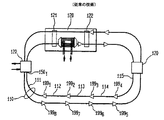
図4を参照すると、ファイバ切断とモニタ回路450の間に配置されたEDFAの数に関係なく、ファイバ切断を検出するモニタ装置または回路450を有するWDMリングの例示的な実施形態が示されている。リングは、内部作動ループ419と保護ループ420によって接続されている保護スイッチ(protection switches)421と422を有する複数のアドドロップネットワーク要素400を含み、各ループは、複数のEDFA499を含む。図4に示すように、信号がサブリンク411でWDMノードまたはネットワーク要素4001に入るとき、信号の部分が選択され、モニタ装置または回路4501に供給される。回路4501は、2つの近接スペクトルバンドでパワーを検出し、2つのスペクトルバンドパワーの差を比較し、比較により、両方のスペクトルバンドのパワーが、ほぼ1に等しいことを示した場合、フラグを立てることができる。本発明によれば、図4に示すように、WDMネットワーク要素4001は、2つのモニタ回路4501と4502を含む。回路4501は、図に示すように作動ループ419を監視し、一方回路4502は保護ループ420を監視する。回路4501に供給されない信号の部分はデマルチプレックスされ、除去されるか、またはノード4001を通って境界決定ノード4002に供給される。
【0017】
モニタ回路4501と4502の他に、ネットワーク要素400は、外部レーザ460を含むことも可能であり、マーカ波長または信号を外側の保護ループ420上に挿入する。図4の外側のループまたは保護リング420上の信号は、図に示すように反時計回りに伝播する。レーザ460は、一方向経路にスイッチしたリングなどのリング構造において必要であり、このようなリングでは、作動ファイバ上に欠陥があるまで、保護ファイバが信号を搬送しない。つまり、通常の動作中に、全ての信号が、図4の作動ファイバ上でのみ、または内部ループ420上でのみ時計回り方向に伝播する場合、レーザ460は保護ループ419において必要となる。他方、双方向ラインにスイッチしたリングなど、通常の動作中に両方のファイバが信号を搬送するリング構造では、追加のレーザは必要でない。
【0018】
図5を参照すると、それぞれ複数のEDFA599を含んでいる、作動ファイバ566と568および保護ファイバ567と569によって相互接続されている終点(end point)ネットワーク要素5001と5002を含む、多様な経路のポイントツーポイント構造を有する本発明の例示的な実施形態が示されている。各ネットワーク要素500のモニタ回路550は、本発明によりファイバ切断を検出する。本発明のこの実施形態では、WDMネットワーク要素500は、リング構造の場合のように、追加のレーザを必要としない。これは、同じ信号が、作動ファイバ566と保護ファイバ567の両方で送信されるためである。図4のリング構造の実施形態の場合のように、モニタ回路550は、2つの近接スペクトルバンドでパワーを検出し、2つのスペクトルバンドのパワーの差を比較し、両方のスペクトルバンドのパワーがほぼ1に等しい場合、フラグを立てることができる。ノード5001の回路550が、作動ファイバ566上でファイバ切断または信号の損失のフラグを立てるとき、ノード5001は、選択スイッチ577を介して信号を保護ファイバ567にスイッチする。図5に示したものとは対照的に、ホットスタンバイ信号が予備(standby)チャネルを介して送信されない場合、通常の動作中に保護ライン上で追加のレーザを必要とする可能性がある。
【0019】
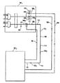
図4と図5に示す本発明の他の態様は、ファイバ経路に沿って固定利得の、すなわち利得を固定したEDFA490と590を使用することである。固定利得または固定増幅器は、補償または安定化チャネルとして知られている、余剰チャネルを送信信号に挿入することによって一定レベルに保たれている出力パワーを有するEDFAである。補償チャネルを使用して、チャネルを信号から除去する度に、送信チャネルの数を数え、残りのチャネルのパワーを増大しなければならないことを回避する。図4を参照すると、補償チャネルを有し、並びに光増幅器回路499を有する固定利得EDFA490は、補償チャネルをファイバに挿入するために使用する回路498をも含む。補償チャネルは、主に、信号またはいくつかのチャネルがファイバから除去されるネットワークの点で、すなわち波長分割多重アドドロップマルチプレクサ(WADM)において、一定な合計パワーレベルを維持するために使用される。補償チャネルは、通常、チャネルの利得にほぼ等しい利得を有する波長で伝送される。補償チャネルは、2つのチャネルの間にあるか、またはEDFA通過帯域の平坦な利得部分のすぐ内側にあるスペクトル領域とすることが可能である。補償チャネルのパワーレベルは、チャネルがWADMで除去される度に、またその反対の度に、一定の出力パワーを保つように増大する。
【0020】
図6Aを参照すると、ファイバが無傷であるとき、ファイバ切断または信号の損失を検出するために本発明により使用するマーカ波長または補償チャネル620およびスペクトルバンド630の例示的実施形態が図示されている。また図6Aには、WDMシステムで情報を転送するために使用する、信号波長またはチャネル640が示されている。本発明によれば、マーカ波長620は、以下で議論する任意の方法で発生することができる。スペクトルバンド領域630は、マーカ波長領域620に十分近接するように選択され、したがって正確な比較を行うことができる。また、スペクトルバンドを作動信号チャネル640から十分遠く選択し、フィルタを用いて分離することができる。
【0021】
固定利得増幅器を使用する場合、何ら設備を追加せず、または固定利得EDFAの補償チャネルのパワーを変調あるいは増大せずに、ファイバ切断または信号の損失を検出することが可能であることを見出した。本発明によれば、補償チャネルと無信号(non−signal)スペクトルバンドの間のパワーレベル比または差を監視する場合、ファイバ切断を確実に検出することが可能である。図6Aに示すように、ファイバが無傷のとき、マーカまたは補償信号620および作動信号640がスペクトルに存在する。スペクトルバンド630は、増幅誘導放出(amplified stimulated emission)によって与えられるパワーからなり、線631と632によって形成された領域内に拘束されている。本発明のこの態様によれば、スペクトルバンド630は、マーカ波長620とスペクトルバンド630の両方の増幅誘導放出がほぼ等しいように選択される。したがって、ファイバが無傷のとき、図6Aに示すように、マーカ620とスペクトルバンド630のパワー比は、1よりはるかに大きい。一方、図6Bに示すように、ファイバ切断または信号の損失を生じる何らかの他の事象があるとき、マーカ波長620と近接スペクトルバンド630のパワー比は、ほぼ1に等しい。マーカ波長620として補償チャネルを使用することにおいて、あらゆる設備を追加することを回避し、潜在的な利得の変化を削除し、マーカ波長620を発生する他の手法で生じる可能性のある、信号チャネルの混変調の可能性を削除する。
【0022】
マーカ波長620は、ネットワーク要素内でEDFAに光利得固定を使用する場合、およびEDFAを固定することを獲得するために使用する光パワーが、次のネットワーク要素に伝播することが可能である場合、作動ファイバに対し容易に発生することができる。したがって、図4を参照すると、WDMのノード400において、マルチプレクサ430に続いて配置されている増幅器が固定利得増幅器4901である場合、ファイバリンク上に挿入された増幅器4911と4912は、固定利得EDFAである必要はない。したがって、本発明は、EDFAを固定することを獲得するために使用した光パワーが、ループの次のノード400に伝播することが可能である場合、WDMノード400においてのみ、固定利得EDFAを必要とする。この本発明の利点は、図5に示すポイントツーポイント構造に同じように適用することができる。また、図4で、増幅器4901が固定利得増幅器であることを要求する代わりに、ネットワーク要素4001の出力で、マーカ波長を挿入することがより便利である可能性があることに留意する。したがって、ネットワーク構造は、WDMノードの設計に依存しない。すなわち、適切に固定利得EDFAを配置することによってマーカ波長を挿入することは、ネットワークの計画者の判断に委ねられることになる。
【0023】
一方、本分析は、固定利得増幅器補償チャネルを使用することによってマーカ波長620を発生することは、保護ファイバが欠陥状態中に信号を搬送するWDMリング用の保護ファイバ上では、可能ではないことを見出した。マーカチャネルを発生することは可能であるが、保護スイッチングを必要とする全ての欠陥がこの方法で検出されるわけではなく、ある場合では、必要でないときに保護スイッチングが初期設定される。図4に示すように、入力および出力保護スイッチの間で、示しているように配置された追加のレーザ460は、リング構造に依存する保護ファイバ用の各ネットワーク要素において、必要である可能性があることを見出した。
【0024】
本発明の他の態様によれば、図6Cに示すように、補償チャネルが利用可能でない場合、すなわち固定利得EDFAを使用していない場合、線649と651の間の領域として表されている信号波長領域650と、線634と636の間の領域として表されている近接スペクトルバンド635の比を使用して、ファイバ切断を検出することが可能である。再び、上述したように、ファイバが無傷のとき、波長領域650とバンド635のパワー比は、1よりはるかに大きい。一方、ファイバ切断があるとき、図6Bのスペクトルが得られ、領域650とバンド635の比、またはより正確には波長範囲の比はほぼ1である。我々は、この検出方法は、実際の信号波長が使用されていて、トラフィックを搬送しているスパンに限定されていることを認識している。すなわち、波長領域650でパワーがないスパンでは、領域635とバンド650のパワー比は、ファイバが無傷であっても、ほぼ1である。この本発明のこの態様に対する欠点は、補償チャネルを伝播させる場合を助長する。もちろん、固定利得EDFAを備えず、したがって補償チャネルを備えない光ネットワークでは、ネットワークオペレータは、リンクが顧客サービスに関して機能するまで、ファイバ切断に対してリンクを監視するために使用することができる、キープアライブ信号として信号波長を発生することが可能である。また、図6Cで使用した手法は、偽否定を発生することが可能である。しかし、ネットワークオペレータは、キープアライブ信号を発生して、偽否定の発生を防ぐことが可能である。
【0025】
図7は、本発明による、図4のサブリンク413でのファイバ切断のシミュレーションを示す。図7に示すように、ファイバが無傷のとき、近接スペクトルバンド730に対するマーカチャネル720のパワーレベルの比は、1よりはるかに大きい。したがって、マーカチャネル720とスペクトルバンド730のパワーの差710は、デシベル単位で、ゼロよりはるかに小さく、約−35dBである。一方、サブリンク413にファイバ切断があるとき、パワー比は1に近く、パワーの差710はゼロdBに近い。図4の他のサブリンクで、ファイバ切断に対し同様の結果が得られた。本発明によれば、ファイバ切断は100μsの時間枠内で検出可能であり、Public Switched Telecommunications Networkで破局的な欠陥を検出するために割り当てられる10msの時間枠内では十分に検出可能である。ファイバ切断と新しいパワーの確立の間の時間は、図3に示すように、約250μs未満であることを必要とすることに留意されたい。したがって、本方法によって、対照がよりはっきりしているだけでなく、より速くスイッチが行われる。図7の結果は、マーカ730とバンド720が、ほぼ等しい利得を有することを仮定している。マーカ730とバンド720が異なる利得を有する場合、パワー比は異なる可能性があるが、パワー比の十分に大きな差は、多数のEDFAに対し検出可能である。
【0026】
作動中、補償チャネルまたはマーカ620のパワーを増大して、より良好なコントラストを達成すること、または単に補償チャネルを使用してファイバ切断を検出することを考慮するべきであることに留意した。補償チャネルのパワーを増大すると、コントラストが増大する可能性があるが、同時に、固定利得増幅器の利得と連鎖内のチャネルあたりのパワーを低減する可能性があることを見出した。代替として、EDFAを動作点に対して再設計することが可能であり、そうすると、補償チャネルのパワーが増大するとき、利得が一定に保たれる。さらに、増幅器が設計されているよりも大きい同等入力を有する固定利得EDFAによる利得傾斜を回避するように注意しなければならない。作動信号640を減衰し、その後EDFAに入れることによって、利得の傾きを克服することができることを見出した。固定利得EDFAに関する限り、減衰はいくつかのチャネルを除去することと等価であり、それにより補償チャネルのパワーを増大する。
【0027】
上記の説明は、本発明の例である。当業者によって、本発明の範囲および精神から逸脱することなく、多くの修正および変更を実施することが可能である。
【図面の簡単な説明】
本発明のこれらの利点および他の利点は、添付の図面と共に、以下の詳細な説明から理解することができる。
【図1】 EDFAを使用する従来の技術のWDMリングを示す図である。
【図2】 図1に示すWDMネットワークに対し、モニタ点でファイバ切断の合計出力パワーを測定した結果である。
【図3】 図1に示すWDMネットワークに対し、マーカ波長の1ナノメートルの帯域で、ファイバ切断の合計パワーをシミュレーションした結果である。
【図4】 本発明による、EDFAを使用するWDMリング体系を示す図である。
【図5】 本発明による、EDFAを使用するポイントツーポイントWDM体系を示す図である。
【図6A】 ファイバが無傷であるとき、本発明による、ファイバ切断を検出するために使用する、マーカ波長と無信号(non−signal)スペクトル領域を有する、全ての光ネットワークに関するパワースペクトルの図である。
【図6B】 ファイバ切断後、本発明による、ファイバ切断を検出するために使用する、マーカ波長と無信号スペクトル領域を有する、全ての光ネットワークに関するパワースペクトルの図である。
【図6C】 ファイバが無傷であるとき、本発明の他の態様による、ファイバ切断を検出するために使用する無信号スペクトル領域を有する、全ての光ネットワークに関するパワースペクトルの図である。
【図7】 マーカチャネルと近接無信号(nearby non−signal)チャネルにおけるファイバ切断前後の光パワーのシミュレーション結果と、本発明によるそれらのパワー比を示す図である。[0001]
(Field of Invention)
The present invention relates to wavelength division multiplexing (WDM) systems, and more particularly to failure detection in WDM systems.
[0002]
(Background of the Invention)
WDM technology has provided a cost-effective solution for the consumption of fibers in a communication network by increasing the network data throughput without the need to install new fibers. In a WDM system, each of several input signals enters a WDM node or network element and is typically assigned in a band of 1550 nanometers (nm) or converted to a specific wavelength. After wavelength conversion, each individual signal wavelength or channel is multiplexed by wavelength division multiplexing and transmitted on the same fiber. In order for WDM technology to be truly feasible as a network solution, a WDM system must also be able to withstand failures that occur in any network. The problem of network survival is that in WDM systems, fiber loss can be catastrophic and expensive when considering large amounts of consumer data, such as multi-gigabit data transferred over a single fiber by the WDM system. It will be important.
[0003]
In response to concerns regarding the survival of WDM networks, self-healing WDM rings and point-to-point divers protection schemes have been proposed. A self-healing ring is a network architecture that connects nodes in a physical ring topology with bandwidth sharing and self-healing capabilities to overcome network deficiencies. To describe this, each node of the ring is connected to other nodes via fibers. If other failures occur, such as fiber cuts or node failures, the ring automatically switches to standby fiber, and in some cases switches to standby electronics. Similarly, point-to-point diverse protection systems protect networks from fiber cable breaks by automatically switching consumer data to spare fibers that are routed along different paths. In either case, automatic protection switching is performed optically, i.e. by switching the received optical signal to a spare fiber, or electrically, i.e. by switching the electrical indication of the received optical signal. It is possible. Automatic protection switching of a WDM network ensures a significant cost saving compared to pure synchronous optical network (SONET) protection. However, some basic issues must be addressed before automatic protection switching can be used in a WDM system.
[0004]
One such fundamental problem for WDM systems is detecting fiber cuts on optically amplified links. Fiber breakage or signal loss detection has proven to be a difficult problem in WDM systems because the link between nodes is usually optically amplified by an erbium doped fiber amplifier (EDFA). In general, at each WDM node, after multiplexing and before transmission over a network fiber facility or link, the signal is amplified by an EDFA. Similarly, after reception, the signal at each WDM node is again amplified by another EDFA and then demultiplexed. Depending on the distance between the transmitter and the receiver, one or several additional EDFAs can be placed at specific points along the fiber path. As the fiber cut and optical monitor or receiver distance and the number of amplifiers increase, the amplified spontaneous emission from the EDFA increases for each EDFA in the optical path. In particular, when there is no optical input signal in a saturated EDFA, amplified spontaneous emission can increase sufficiently after going through several EDFAs, and fiber cuts may not be detected. In fact, due to amplified spontaneous emission, measuring total optical power or even measuring optical power in the spectral band is not sufficient to measure certain fiber breaks.
[0005]
Depending on the position of the fiber cut relative to the EDFA and the detection threshold, the total optical power may not be detected. On some fiber links or spans, there are no EDFAs in the node or network element beyond that range, but on others there can be multiple EDFAs. FIG. 1 represents a conventional working fiber / protection fiber pair in a WDM ring and includes a network add-
[0006]
For the number of interleaved EDFA 199,
[0007]
The results shown in FIG. 2 were confirmed by the measurements performed on the test bench. Based on simulations and test bench measurements, the following conclusions were drawn regarding succinctly monitoring optical power and detecting fiber breaks in WDM systems. When there is no EDFA between the fiber cut and the monitor point, the fiber cut can be accurately identified. If there is one EDFA between the fiber cut and the monitor, accurate fiber cut identification cannot be achieved without careful selection of the detection threshold used to detect the fiber cut. When three or more EDFAs are arranged between the monitor point and the fiber cut, it is not possible to set a threshold considering the fiber cut detection.
[0008]
Also, instead of detecting the total optical power of the fiber, the power was monitored within a narrower spectral band, and an investigation was made to detect fiber cut at the
[0009]
Other methods are also known in the art. One such method is described in J. Org. L. Zyskind is described in US Patent Application No. 6,008,915, entitled “Method of Identifying Faults in WDM Optical Networks”. In that method, Zyskind et al. Uses an additional laser to insert an additional monitoring channel into the fiber of the WDM system along the signal channel. The monitor channel power and amplified spontaneous emission by the EDFA used along the fiber path are then monitored and compared to detect defects. That is, the power change for the monitor channel and amplified spontaneous emission in the same direction are both increased or decreased, for example, and the signal channel is interpreted as being removed or added. On the other hand, the change in power for the monitor channel in the opposite direction and amplified spontaneous emission is interpreted as an overall loss indicative of a defect. The Zynkind et al. Method requires additional components including a monitoring laser, a coupler, and a bandpass filter to implement. More importantly, as the number of channels is added or removed, the power level of the monitor channel and amplified spontaneous emission change, thereby changing the threshold level for detecting defects. Also, Zynkind's method requires a fairly high performance detector and is required to keep track of five different cases for possible upstream losses and signal channels. Therefore, this method probably requires decision-making software.
[0010]
An article titled “A Novel In-Service Surveillance Scheme for Optically Amplified Transmission Systems” (published in 1997, IEEE Photonics Technology, H., published by IEEE Photonics Technology. Other conventional techniques for detecting defects in a WDM system are described. Chan et al. Uses the EDFA's non-flat amplified spontaneous emission spectrum as the light source and monitors the fiber channel for defects. By Chan et al., The fiber Bragg grating is placed close to the input end of each EDFA along the fiber path, except for the first EDFA following the transmitter. Each fiber Bragg grating then filters out significant wavelengths within the unused spontaneous emission spectrum. Each filtered wavelength is assigned to each amplifier immediately in front of the fiber Bragg grating. Since the fiber Bragg grating operates as a notch filter, the power loss that occurs upstream of the fiber Bragg grating becomes a spectral pulse at a significant wavelength of the fiber Bragg grating. This method allows the fiber cut to be localized in the fiber span between any two amplifiers. This method does not require the use of an additional laser, but requires a fiber Bragg grating as an additional component. This method also requires high performance spectral monitoring. Also, this method may not be able to detect fiber breaks that occur between the fiber Bragg grating and the input of its assigned amplifier, and it may not be able to detect a partial defect of an amplifier.
[0011]
All of the above approaches require additional components or cannot detect all fiber cuts, regardless of the position of the fiber cuts relative to the amplifier or the number of amplifiers.
[0012]
(Summary of Invention)
The present invention provides a method and system for unambiguously detecting fiber cuts in an optical network regardless of the number of EDFAs placed between the fiber cuts and the monitoring points.
[0013]
According to the invention, the marker wavelength is detected at the output of the network elements forming part of the WDM network. The marker power level is then compared to the power level in the non-signal wavelength region. If the ratio of the power level in the marker wavelength spectral band to the power level in the no-signal wavelength region is large, the fiber is intact. In contrast, if the ratio between the power level of the no-signal wavelength region and the marker wavelength spectral band is approximately equal to 1, there is a fiber cut.
[0014]
The present invention unambiguously identifies fiber cuts by adding only a modest amount of cost and complexity to the WDM network and requiring only one additional laser at each network element of the WDM ring architecture. Provide enough information. Furthermore, according to the present invention, additional lasers may not be required in certain ring and point-to-point configurations. Furthermore, regardless of the configuration of the WDM network, the present invention only requires a circuit that can measure the power difference in two adjacent spectral regions in order to measure fiber cuts.
[0015]
According to the present invention, a fiber cut can be detected regardless of the number of EDFAs between the fiber cut and the monitoring point, thereby generating false alarms or false negatives. Eliminated. The definition of false negative is that a signal loss is detected when there is no signal loss.
[0016]
(Detailed explanation)
Referring to FIG. 4, an exemplary embodiment of a WDM ring having a monitoring device or
[0017]
[0018]
Referring to FIG. 5, an end
[0019]
Another aspect of the present invention shown in FIGS. 4 and 5 is to use EDFAs 490 and 590 with fixed gain, ie, fixed gain, along the fiber path. A fixed gain or fixed amplifier is an EDFA having an output power that is kept at a constant level by inserting an extra channel into the transmitted signal, known as a compensation or stabilization channel. The compensation channel is used to avoid having to count the number of transmission channels and increase the power of the remaining channels each time a channel is removed from the signal. Referring to FIG. 4, a fixed gain EDFA 490 having a compensation channel and having an
[0020]
Referring to FIG. 6A, an exemplary embodiment of a marker wavelength or
[0021]
When using a fixed gain amplifier, it has been found that it is possible to detect fiber cuts or signal loss without adding any equipment or modulating or increasing the power of the compensation channel of the fixed gain EDFA. . According to the present invention, fiber breaks can be reliably detected when monitoring the power level ratio or difference between the compensation channel and the non-signal spectral band. As shown in FIG. 6A, when the fiber is intact, a marker or
[0022]
[0023]
On the other hand, this analysis shows that generating a
[0024]
According to another aspect of the invention, as shown in FIG. 6C, the signal represented as the region between
[0025]
FIG. 7 shows a simulation of fiber cutting at the
[0026]
It was noted that in operation, one should consider increasing the power of the compensation channel or
[0027]
The above description is an example of the present invention. Many modifications and variations can be made by those skilled in the art without departing from the scope and spirit of the invention.
[Brief description of the drawings]
These and other advantages of the present invention can be understood from the following detailed description in conjunction with the accompanying drawings.
FIG. 1 illustrates a prior art WDM ring using an EDFA.
FIG. 2 is a result of measuring the total output power of fiber cutting at a monitoring point for the WDM network shown in FIG. 1;
FIG. 3 is a result of simulating the total power of fiber cutting in the marker wavelength band of 1 nanometer for the WDM network shown in FIG. 1;
FIG. 4 is a diagram illustrating a WDM ring system using an EDFA according to the present invention.
FIG. 5 is a diagram illustrating a point-to-point WDM scheme using an EDFA according to the present invention.
FIG. 6A is a power spectrum diagram for all optical networks with marker wavelength and non-signal spectral region used to detect fiber breaks when the fiber is intact, according to the present invention. is there.
FIG. 6B is a power spectrum diagram for all optical networks with marker wavelength and no-signal spectral region used to detect fiber breaks after fiber cut according to the present invention.
FIG. 6C is a power spectrum diagram for all optical networks with a no-signal spectral region used to detect fiber breaks when the fiber is intact, according to another aspect of the invention.
FIG. 7 is a diagram showing simulation results of optical power before and after fiber cutting in a marker channel and a near non-signal channel and their power ratio according to the present invention.
Claims (15)
マーカ波長を発生するステップと、
該一つのノードにおいて、前記発生したマーカ波長と近接スペクトルバンド内の異なる波長のパワー比を検出するステップと
を含むことを特徴とする方法。In a wavelength division multiplexing system comprising at least two nodes connected by a fiber to which at least one fiber amplifier is coupled, a method for detecting a fiber break at one of said nodes, comprising:
Generating a marker wavelength; and
Detecting at said one node a power ratio between said generated marker wavelength and a different wavelength within a near spectral band.
前記検出ステップでほぼ1に等しい比を示した場合、ファイバ切断があると判断すること
をさらに含むことを特徴とする請求項1に記載の方法。If the detecting step shows a ratio much greater than 1, determining that there is no fiber cut;
The method of claim 1, further comprising determining that there is a fiber cut if the detecting step shows a ratio approximately equal to one.
補償チャネルを第一の波長で発生するための回路と、
前記発生した補償チャネルと、異なる波長の、かつ前記補償チャネルとほぼ同一利得を有するスペクトルバンドのパワー比を検出するための回路とを含み、
前記発生するための回路および前記検出するための回路は、ファイバに沿った任意の位置で切断が検出されるようにファイバに結合されていることを特徴とするシステム。A system for detecting a fiber cut on a fiber having at least one fiber amplifier between the monitoring point and the fiber cut,
A circuit for generating a compensation channel at a first wavelength;
A circuit for detecting the generated compensation channel and a power ratio of spectral bands of different wavelengths and having substantially the same gain as the compensation channel;
The system for generating and the circuit for detecting are coupled to a fiber such that a break is detected at any location along the fiber.
前記ファイバ内にある複数の増幅器と、
前記ファイバの一つにあるファイバ切断を検出する手段であって、該一つのファイバの上のマーカ波長と近接スペクトルバンド上の異なる波長のパワー比を比較する手段を備える手段と
を含むことを特徴とする波長分割多重システム。At least two node elements interconnected by a working optical fiber and a spare optical fiber;
A plurality of amplifiers in the fiber;
Means for detecting a fiber cut in one of the fibers, the means comprising means for comparing the marker wavelength on the one fiber and the power ratio of the different wavelengths on the near spectrum band. Wavelength division multiplexing system.
ファイバ上のモニタ点において第1の波長を有する第1のスペクトルバンドのパワーと、異なる波長を有する隣接スペクトルバンドのパワーとのパワー比を比較することを含むことを特徴とする方法。A method for detecting fiber breaks in a wavelength division multiplexing system having at least one amplifier between two node elements comprising:
Comparing the power ratio between the power of a first spectral band having a first wavelength and the power of an adjacent spectral band having a different wavelength at a monitoring point on the fiber.
Applications Claiming Priority (3)
| Application Number | Priority Date | Filing Date | Title |
|---|---|---|---|
| US09/156,715 | 1998-09-18 | ||
| US09/156,715 US6115154A (en) | 1998-09-18 | 1998-09-18 | Method and system for detecting loss of signal in wavelength division multiplexed systems |
| PCT/US1999/019599 WO2000018043A1 (en) | 1998-09-18 | 1999-08-26 | Method and system for detecting loss of signal in wavelength division multiplexed systems |
Publications (2)
| Publication Number | Publication Date |
|---|---|
| JP2002525966A JP2002525966A (en) | 2002-08-13 |
| JP3670583B2 true JP3670583B2 (en) | 2005-07-13 |
Family
ID=22560759
Family Applications (1)
| Application Number | Title | Priority Date | Filing Date |
|---|---|---|---|
| JP2000571589A Expired - Fee Related JP3670583B2 (en) | 1998-09-18 | 1999-08-26 | Method and system for detecting signal loss in wavelength division multiplexing systems |
Country Status (10)
| Country | Link |
|---|---|
| US (1) | US6115154A (en) |
| EP (1) | EP1114531B1 (en) |
| JP (1) | JP3670583B2 (en) |
| KR (1) | KR20010075159A (en) |
| CN (1) | CN1318235A (en) |
| AU (1) | AU748446B2 (en) |
| CA (1) | CA2343211C (en) |
| ID (1) | ID28465A (en) |
| TW (1) | TW431076B (en) |
| WO (1) | WO2000018043A1 (en) |
Families Citing this family (29)
| Publication number | Priority date | Publication date | Assignee | Title |
|---|---|---|---|---|
| FI106683B (en) * | 1998-11-10 | 2001-03-15 | Nokia Networks Oy | Certification in optical communication system |
| DE19910646C1 (en) * | 1999-03-10 | 2000-11-16 | Siemens Ag | Transparent fiber optic communication network |
| US6577415B1 (en) * | 1999-06-15 | 2003-06-10 | Lucent Technologies Inc. | Optical add-drop module with low loss and high isolation |
| US6414765B1 (en) * | 2000-03-07 | 2002-07-02 | Corning, Inc. | Protection switch in a two-fiber optical channel shared protection ring |
| EP1133082A1 (en) * | 2000-03-10 | 2001-09-12 | Corning Incorporated | Optical monitoring system |
| US6735390B1 (en) * | 2000-10-31 | 2004-05-11 | Lucent Technologies Inc. | Method and apparatus for terminating optical links in an optical network |
| US6782198B1 (en) * | 2000-11-10 | 2004-08-24 | Lucent Technologies Inc. | Switching arrangement for fault recovery in optical WDM ring networks |
| US6816680B2 (en) * | 2000-12-12 | 2004-11-09 | Nortel Networks Limited | Optical communications network and nodes for forming such a network |
| US6556319B2 (en) | 2001-05-08 | 2003-04-29 | Dorsal Networks, Inc. | Split redundant trunk architecture using passive splitters and path switching |
| US20040105136A1 (en) * | 2001-05-08 | 2004-06-03 | Corvis Corporation | Interconnections and protection between optical communications networks |
| JP4576756B2 (en) * | 2001-06-19 | 2010-11-10 | 株式会社日立製作所 | Optical signal switching device and method of using the same |
| FR2828776A1 (en) * | 2001-08-16 | 2003-02-21 | Cit Alcatel | METHOD FOR SECURING AN OPTICAL TRANSMISSION SYSTEM, DEVICE FOR IMPLEMENTING SAID METHOD AND OPTICAL TRANSMISSION SYSTEM INCORPORATING SUCH A DEVICE |
| AU2002341893A1 (en) * | 2001-10-01 | 2003-04-14 | Nortel Networks Limited | Fault signalling in optical communications networks |
| US7263151B2 (en) * | 2002-03-04 | 2007-08-28 | Broadcom Corporation | High frequency loss of signal detector |
| IL148811A (en) * | 2002-03-21 | 2007-03-08 | Eci Telecom Ltd | Method of locating faults in optical telecommunication networks |
| US7116905B2 (en) * | 2002-03-27 | 2006-10-03 | Fujitsu Limited | Method and system for control signaling in an open ring optical network |
| US7231148B2 (en) * | 2002-03-28 | 2007-06-12 | Fujitsu Limited | Flexible open ring optical network and method |
| US7181137B1 (en) * | 2002-09-30 | 2007-02-20 | Cisco Technology, Inc. | Subband spectrum analysis for optical multiplex section protection |
| ITMI20030050A1 (en) * | 2003-01-15 | 2004-07-16 | Marconi Comm Ltd | OPTIC AMPLIFIED RING TRANSMISSION SYSTEM |
| WO2005026815A1 (en) * | 2003-09-10 | 2005-03-24 | Nabtesco Corporation | Optical path switching device |
| ITMI20032365A1 (en) * | 2003-12-03 | 2005-06-04 | Marconi Comm Ondata Gmbh | OPTICAL NETWORKS. |
| US20050174563A1 (en) * | 2004-02-11 | 2005-08-11 | Evans Alan F. | Active fiber loss monitor and method |
| CA2498441C (en) * | 2004-02-26 | 2009-10-13 | Tropic Networks Inc. | Methods and apparatus for detecting a faulty component location along an optical path in an optical network |
| US20050196169A1 (en) * | 2004-03-03 | 2005-09-08 | Fujitsu Limited | System and method for communicating traffic between optical rings |
| WO2007044939A2 (en) | 2005-10-13 | 2007-04-19 | Opvista Incorporated | Optical ring networks using circulating optical probe in protection switching with automatic reversion |
| US8078052B2 (en) * | 2007-10-18 | 2011-12-13 | Cisco Technology, Inc. | Protocol-less all-optical 1+1 bidirectional revertive linear protection system |
| US9525479B2 (en) * | 2012-01-24 | 2016-12-20 | Telefonaktiebolaget Lm Ericsson (Publ) | Apparatus and method for optimizing the reconfiguration of an optical network |
| KR101581507B1 (en) | 2013-10-22 | 2015-12-30 | 주식회사 더즈텍 | Loss of signal detector |
| US10707638B2 (en) | 2017-11-13 | 2020-07-07 | Neptune Subsea Ip Limited | Integrated signal loss detection in Raman amplified fiber spans or other fiber spans |
Family Cites Families (11)
| Publication number | Priority date | Publication date | Assignee | Title |
|---|---|---|---|---|
| US4633246A (en) * | 1984-01-09 | 1986-12-30 | Fiberlan, Inc. | Time divison multiplex ring |
| US4726676A (en) * | 1986-02-06 | 1988-02-23 | General Signal Corporation | Optical signal power measurement method and apparatus |
| US4883054A (en) * | 1987-12-09 | 1989-11-28 | Fuller Research Corporation | Optical fiber break detector |
| IT1247845B (en) * | 1991-03-29 | 1995-01-02 | Pirelli Cavi Spa | OPTICAL FIBER TELECOMMUNICATION LINE WITH PROTECTION DEVICE FOR OPTICAL AMPLIFIERS |
| US5335104A (en) * | 1992-10-22 | 1994-08-02 | Laser Precision Corp. | Method of detecting breaks in multi-drop feeder systems |
| US5680235A (en) * | 1995-04-13 | 1997-10-21 | Telefonaktiebolaget Lm Ericsson | Optical multichannel system |
| BR9510642A (en) * | 1995-09-15 | 1999-11-30 | Pllb Elettronica S P A | For monitoring a fiber optic cable |
| US6008915A (en) * | 1996-02-16 | 1999-12-28 | Lucent Technologies, Inc. | Method of identifying faults in WDM optical networks |
| GB2315938B (en) * | 1996-08-01 | 2001-02-28 | Northern Telecom Ltd | Optical transmission system fault analysis |
| US6057948A (en) * | 1997-11-03 | 2000-05-02 | Ciena Corporation | Protection switch optical communications system |
| US6011623A (en) * | 1998-06-09 | 2000-01-04 | Macdonald; Robert I. | Fault detection system for an amplified optical transmission system |
-
1998
- 1998-09-18 US US09/156,715 patent/US6115154A/en not_active Expired - Lifetime
-
1999
- 1999-08-26 TW TW088114629A patent/TW431076B/en not_active IP Right Cessation
- 1999-08-26 JP JP2000571589A patent/JP3670583B2/en not_active Expired - Fee Related
- 1999-08-26 WO PCT/US1999/019599 patent/WO2000018043A1/en not_active Application Discontinuation
- 1999-08-26 ID IDW20010654A patent/ID28465A/en unknown
- 1999-08-26 CA CA002343211A patent/CA2343211C/en not_active Expired - Fee Related
- 1999-08-26 KR KR1020017003423A patent/KR20010075159A/en not_active Application Discontinuation
- 1999-08-26 EP EP99945244A patent/EP1114531B1/en not_active Expired - Lifetime
- 1999-08-26 AU AU57881/99A patent/AU748446B2/en not_active Ceased
- 1999-08-26 CN CN99810974A patent/CN1318235A/en active Pending
Also Published As
| Publication number | Publication date |
|---|---|
| TW431076B (en) | 2001-04-21 |
| EP1114531A4 (en) | 2006-03-29 |
| AU5788199A (en) | 2000-04-10 |
| JP2002525966A (en) | 2002-08-13 |
| CA2343211C (en) | 2006-03-14 |
| EP1114531A1 (en) | 2001-07-11 |
| AU748446B2 (en) | 2002-06-06 |
| EP1114531B1 (en) | 2013-01-23 |
| CN1318235A (en) | 2001-10-17 |
| CA2343211A1 (en) | 2000-03-30 |
| KR20010075159A (en) | 2001-08-09 |
| US6115154A (en) | 2000-09-05 |
| WO2000018043A1 (en) | 2000-03-30 |
| ID28465A (en) | 2001-05-24 |
Similar Documents
| Publication | Publication Date | Title |
|---|---|---|
| JP3670583B2 (en) | Method and system for detecting signal loss in wavelength division multiplexing systems | |
| CA2215115C (en) | System and method for mitigating cross-saturation in optically amplified networks | |
| US10826601B2 (en) | Optical switch with path continuity monitoring for optical protection switching | |
| US6317231B1 (en) | Optical monitoring apparatus and method for network provisioning and maintenance | |
| JP4336377B2 (en) | Optical multichannel system | |
| US6404525B1 (en) | Optical add-drop multiplexer | |
| US6215565B1 (en) | Method of and system for diagnosing optical system failures | |
| EP0988727B1 (en) | Span management system for wavelength division multiplexed network | |
| US9065247B2 (en) | Differentiation of power and channel count changes in optically amplified links | |
| JPH10126350A (en) | Optical network, optical branch insertion node, and fault recovery system | |
| JP6317357B2 (en) | Disaster recovery in branched optical networks | |
| US7254327B1 (en) | Switching status and performance monitoring technology for wavelength selective switch and optical networks | |
| US9391421B2 (en) | Optical amplification apparatus, optical transmission apparatus, and optical transmission system | |
| JP3233204B2 (en) | Wavelength ADM device | |
| JP2000312046A (en) | Optical transmission apparatus, optical amplifier, and optical transmission system | |
| Chan et al. | A novel in-service surveillance scheme for optically amplified transmission systems | |
| EP4346122A1 (en) | Optical signal-to-noise ratio measurement method and apparatus, and computer storage medium | |
| JP4071663B2 (en) | Optical transmission equipment | |
| MXPA01002734A (en) | Method and system for detecting loss of signal in wavelength division multiplexed systems | |
| EP3747140B1 (en) | Optical system and method for seeding an optical transmitter | |
| JP2004173309A (en) | Terminal station equipment, and supervisory and control method, in wdm communication system | |
| Fee et al. | Optical performance monitoring in the MCI network | |
| Richards et al. | Method for detecting fiber cuts in a WDM ring with saturated EDFAs |
Legal Events
| Date | Code | Title | Description |
|---|---|---|---|
| A131 | Notification of reasons for refusal |
Free format text: JAPANESE INTERMEDIATE CODE: A131 Effective date: 20040618 |
|
| A521 | Request for written amendment filed |
Free format text: JAPANESE INTERMEDIATE CODE: A523 Effective date: 20040921 |
|
| RD04 | Notification of resignation of power of attorney |
Free format text: JAPANESE INTERMEDIATE CODE: A7424 Effective date: 20040921 |
|
| TRDD | Decision of grant or rejection written | ||
| A01 | Written decision to grant a patent or to grant a registration (utility model) |
Free format text: JAPANESE INTERMEDIATE CODE: A01 Effective date: 20050401 |
|
| A61 | First payment of annual fees (during grant procedure) |
Free format text: JAPANESE INTERMEDIATE CODE: A61 Effective date: 20050414 |
|
| R150 | Certificate of patent or registration of utility model |
Free format text: JAPANESE INTERMEDIATE CODE: R150 |
|
| FPAY | Renewal fee payment (event date is renewal date of database) |
Free format text: PAYMENT UNTIL: 20080422 Year of fee payment: 3 |
|
| FPAY | Renewal fee payment (event date is renewal date of database) |
Free format text: PAYMENT UNTIL: 20090422 Year of fee payment: 4 |
|
| FPAY | Renewal fee payment (event date is renewal date of database) |
Free format text: PAYMENT UNTIL: 20090422 Year of fee payment: 4 |
|
| FPAY | Renewal fee payment (event date is renewal date of database) |
Free format text: PAYMENT UNTIL: 20100422 Year of fee payment: 5 |
|
| FPAY | Renewal fee payment (event date is renewal date of database) |
Free format text: PAYMENT UNTIL: 20110422 Year of fee payment: 6 |
|
| FPAY | Renewal fee payment (event date is renewal date of database) |
Free format text: PAYMENT UNTIL: 20110422 Year of fee payment: 6 |
|
| S111 | Request for change of ownership or part of ownership |
Free format text: JAPANESE INTERMEDIATE CODE: R313113 |
|
| FPAY | Renewal fee payment (event date is renewal date of database) |
Free format text: PAYMENT UNTIL: 20110422 Year of fee payment: 6 |
|
| R350 | Written notification of registration of transfer |
Free format text: JAPANESE INTERMEDIATE CODE: R350 |
|
| FPAY | Renewal fee payment (event date is renewal date of database) |
Free format text: PAYMENT UNTIL: 20110422 Year of fee payment: 6 |
|
| FPAY | Renewal fee payment (event date is renewal date of database) |
Free format text: PAYMENT UNTIL: 20120422 Year of fee payment: 7 |
|
| LAPS | Cancellation because of no payment of annual fees |