JP3669242B2 - Cable crane control system - Google Patents
Cable crane control system Download PDFInfo
- Publication number
- JP3669242B2 JP3669242B2 JP2000058516A JP2000058516A JP3669242B2 JP 3669242 B2 JP3669242 B2 JP 3669242B2 JP 2000058516 A JP2000058516 A JP 2000058516A JP 2000058516 A JP2000058516 A JP 2000058516A JP 3669242 B2 JP3669242 B2 JP 3669242B2
- Authority
- JP
- Japan
- Prior art keywords
- bucket
- trolley
- rope
- main rope
- traveling
- Prior art date
- Legal status (The legal status is an assumption and is not a legal conclusion. Google has not performed a legal analysis and makes no representation as to the accuracy of the status listed.)
- Expired - Fee Related
Links
Images


Landscapes
- Control And Safety Of Cranes (AREA)
Description
【0001】
【発明の属する技術分野】
本発明は、例えばダムの構築現場などにおいてコンクリートをはじめとする各種資材を搬送するために設置されるケーブルクレーンの制御システムに関する。
【0002】
【従来の技術】
周知のように、例えばダムの構築現場において、コンクリートを製造現場から打設現場まで搬送するための手段の一つとしてケーブルクレーンが用いられている。このケーブルクレーンは、従来、図7に示すように、山間に構築されるダム1上にその長手方向に沿って張設された主索2と、主索2に懸垂されこれに沿って走行可能な横行トロリー3と、この横行トロリー3の牽引用牽索4と、横行トロリー3の下部に吊索5を介して吊下されたコンクリートバケット6と、前記牽索4を牽引して横行トロリー3を山側に設けた搬送開始位置Aとダム1の底部任意位置に設定された搬送終了位置B間を往復移動させる横行ウインチ7と、前記吊索5を巻取,巻き下げしてバケット6を昇降させる縦行ウインチ8と、横行トロリー3の位置およびバケット6の位置を監視するとともに、これら各ウインチ7,8を駆動制御する操作室9を備えている。
【0003】
搬送開始位置Aの側方上部には、紙面と直交する方向に図示しないバッチャープラントで作られたコンクリートを搬送するトランスファーカー10が走行可能に配置される。また、搬送終了位置Bにはコンクリートホッパー11が配置されており、操作室9からの制御信号に基づき、横行トロリー3を横移動させつつバケット6を昇降させ、各位置A,Bにバケット6を位置決めして、コンクリートの供給と排出を行う。
【0004】
この種の構築物には多量のコンクリートを必要とするところから、工費の採算上都合からバケット6の一回あたりの搬送時間を可及的に短縮するために、図示のごとく斜めの軌跡で搬送している。各索4,5の繰り出し量や荷重に応じた主索2の撓み度合い等を検出し、この検出結果に応じて自動的にバケット6や横行トロリー3の座標を算出し、この算出結果に基づき各ウインチ7,8の駆動用制御装置に正逆回転,減速,停止を指令する。この指令によって、横行トロリー3を主索2に沿って横に移動させるとともにバケット6を昇降させて、バケット6を搬送開始位置Aから搬送終了位置Bまで自動搬送する。
【0005】
横行トロリー3の加速時または減速時には、例えば特許2684940号等に開示されているように、横行トロリー3の現在位置および速度並びにバケット6の振れ角度および角速度を検出して、フィードバック制御により各ウインチ7,8を駆動制御してバケット6の振れを相殺している。横行トロリー3の速度はウインチ7に設けた速度計を通じて検出し、バケット6の振れ角度および角速度は当該バケット6に設けたセンサを通じて検出している。
【0006】
【発明が解決しようとする課題】
ところで、このようなケーブルクレーンでは、長期間にわたり使用していると、経時変化等により牽索4や吊索5などのワイヤー類が伸びて緩んだりする場合がある。また、ウィンチ7,8稼働中に牽索4や吊索5などに滑りが発生する場合がある。このような場合に、牽索4や吊索5の繰り出し量を検出しても、横行トロリー3やバケット6の位置を精確に算出することはできず、算出結果に若干の誤差が生じた。このため、特に加速時または減速時の制御においては、横行トロリー3やバケット6の制御を適切に行うことができず、バケット6の振れを十分に相殺し切れなかったり、逆にバケット6の振れを増大させてしまうことがあった。
【0007】
これを補完するために、トータルステーションによる光学的な測距が行われている。しかし、このシステムでは、霧などが発生した場合に、横行トロリー3やバケット6の位置を精確に測定することができず、天候に大きく左右され易いという問題があった。
【0008】
本発明は、このような事情に鑑みてなされたもので、その目的は、ワイヤー類の伸びや滑り、天候などの影響を受けずに横行トロリーやバケットの現在位置を精確に検出することができ、バケットの振れの相殺が十分に可能なケーブルクレーンの制御システムを提供することにある。
【0009】
【課題を解決するための手段】
このような目的を達成するために本発明では、ケーブルクレーンの制御システムを以下のように構成する。
【0015】
(1)ダム等の構築予定構造物を挟んだ一方において二点間に張設された軌索と、この軌索に沿って走行可能な走行トロリーと、該走行トロリー牽引用の走行索と、一端が主索調整装置を介して前記走行トロリーに、他端が前記ダムを挟んだ他方側の固定塔に連結してこれらの間に張設される主索と、該主索に沿って走行可能な横行トロリーと、該横行トロリー牽引用の牽索と、前記横行トロリーの下方に吊索を介して吊下されたバケットと、前記走行索を牽引して前記走行トロリーを軌索に沿って往復移動させる走行ウィンチと、前記主索調整装置の主索調整索を牽引して主索の撓みを調整する主索調整ウィンチと、前記牽索を牽引して前記横行トロリーを主索に沿って往復移動させる横行ウインチと、前記吊索を巻取,巻き下げしてバケットを昇降させる縦行ウインチと、各ウインチを個別に駆動制御可能なウインチ制御装置とを備えた軌索式のケーブルクレーンにおいて、前記バケットを搬送開始位置から搬送終了位置まで移動させる際に使用するケーブルクレーンの制御システムにおいて、前記バケット、前記横行トロリー、前記走行トロリーおよび前記主索調整装置にそれぞれGPS受信機を搭載し、これらの4つのGPS受信機を通じて前記バケット、前記横行トロリー、前記走行トロリーおよび前記主索調整装置の現在位置を逐次測位する構成とする。
【0016】
このシステムにおいても同様、横行トロリー、バケット、走行トロリーおよび主索調整装置にそれぞれGPS受信機を搭載したから、これらの現在位置を主索や牽索、吊索等のワイヤーの伸びや滑り、天候から悪影響を受けずに精確に測位することができる。また、計測速度も速くすることができる。
【0017】
(2)このシステムにあっては、前記ウインチ制御装置は、前記搬送開始位置及び搬送終了位置、前記走行索の繰り出し長さ、前記主索調整索の繰り出し長さ、前記牽索の繰り出し長さ、前記吊索の繰り出し長さ、及びこれらの繰り出し速度を算定要素として、前記軌索、前記主索、前記横行トロリー及び前記バケットの挙動を予め解析してモデル化した運転パターンを多数記憶していて、前記バケットの移動の際に、前記GPS受信機を通じて前記バケットの現在位置を測位して、この測位結果に基づき前記運転パターンの中から適切な運転パターンを選出してその運転パターンに従って前記バケットを搬送すべく前記ウインチを駆動制御する構成とする。
【0018】
これにより、予め定められた運転パターンに従ってバケットを迅速かつ効率よく移動させることができ、制御負荷が軽減するとともに応答性が向上し、もってバケットを目的地まで短時間で移動させることができる。
【0019】
(3)ここで、運転パターンについては、前記軌索、前記走行索、前記主索調整索、前記主索、前記牽索、及び前記吊索を懸垂曲線と仮定して、前記軌索、前記主索、前記トロリー及び前記バケットの挙動を解析してモデル化する構成とする。これにより正確な位置決めや振れ止めを行うことができ、好ましい。
【0020】
(4)前記横行トロリーの加速時または減速時において、前記GPS受信機を通じて測位された前記バケットおよび前記横行トロリーの現在位置に基づき前記横行トロリーの速度並びに前記バケットの振れ挙動を検出して、前記バケットの振れを相殺させるように前記各ウインチを駆動制御する構成とする。これにより、横行トロリーの加速時または減速時においては、測位された横行トロリーおよびバケットの現在位置情報に基づき横行トロリーの速度並びにバケットの振れ角度および角速度を精確に算出して、適切なタイミングでかつ適切なフィードバック量で横行トロリーやバケットを走行制御することができる。
【0021】
(5)前記横行トロリーの加速時および減速時において行うバケットの振れを相殺するための制御を、前記トロリーを同方向に階段状に加速あるいは減速することにより行う構成とする。これにより、横行トロリーやバケットに限らずケーブルクレーン全体に不要な負荷を与えることなく効率的に振れを相殺することができる。
【0022】
(6)前記横行トロリーの加速時および減速時において行うバケットの振れを相殺するための制御をファジー推論により行う構成とする。これにより、迅速かつ円滑な自動運転が可能になるとともに、搬送終了位置での精度の良い位置決め作業が容易になされることになる。
【0023】
(7)前記横行トロリーの加速時及び減速時におけるファジー推論によるフィードバック制御が、加速時には前記バケットの振れ角と振れ方向及び前記横行トロリーの速度を入力することにより行われ、減速時には前記バケットの振れ角と振れ方向及び前記横行トロリーの速度と位置を入力することにより行われ、さらに停止時には前記バケットの振れ角と振れ方向及び前記横行トロリーの速度と位置を入力することにより行われる構成とする。これにより、各タイミングに応じた適切な制御を行うことができる。
【0024】
【発明の実施の形態】
以下に本発明にかかるケーブルクレーンの制御システムの実施形態について添付図面を用いて説明する。図1および図2は、本発明にかかるケーブルクレーンの制御システムの第1実施形態を示したものである。図1はこの発明の全体構成を示す概略図であり、図2はシステム構成を示すブロック図である。なお、この実施の形態では、従来と同様または相当する箇所は同一符号を付すものとする。
【0025】
ケーブルクレーンは、基本的には従来とほぼ同様に、山間に構築されるダム1の上部にその長手方向に沿って張設された主索2と、主索2に懸垂され、これに沿って走行可能な横行トロリー3と、この横行トロリー3の牽引用の牽索4と、横行トロリー3の下部に吊索5を介して吊下されたコンクリートバケット6と、前記牽索4を牽引して横行トロリー3を山側に設けた搬送開始位置Aとダム1の底部任意位置に設定された搬送終了位置B間を往復移動させる横行ウインチ7と、前記吊索5を巻取、巻き下げしてバケット6を昇降させる縦行ウインチ8と、横行トロリー3の位置およびバケット6の位置を監視するとともに、これら各ウインチ7,8を駆動制御するための操作室9とを備えている。
【0026】
搬送開始位置Aには、紙面と直交する方向に図示しないバッチャープラントで造られたコンクリートを搬送するトランスファーカー10が走行し、搬送終了位置Bにはコンクリートホッパー11が設置されている。
【0027】
操作室9には、各ウインチ7,8の運転用操作卓20と、各ウインチ7,8に各種駆動モードを指令する制御部22と、各種指令を出すにあたり必要な演算を行い、その演算結果を制御部22に与える演算部24と、無線機26とを備えている。演算部24は、CPUやメモリ、ハードディスク装置、ディスプレイ等を備えたコンピュータで構成される。
【0028】
主索2の付根部には、傾斜角度検出装置28が設けられている。傾斜角度検出装置28は横行トロリー3の接近位置における主索4の傾斜度合いを検出する。
【0029】
横行ウインチ7および縦行ウインチ8は、主索2の近傍の機械室32に配置されるもので、図2に示すように、駆動制御装置34,36により正逆回転駆動される。駆動制御装置34,36は前記制御部22に接続され、制御部22からの指令に応じて各ウインチ7,8を正逆転及び加減速駆動する。
【0030】
各ウインチ7,8は、それぞれモータ7a,8aにブレーキ7b,8b、減速機7c,8cを介して回転可能に連動し、牽索4,吊索5を巻取および繰り出しするドラム7d,8dを有している。なお、前記横行ウインチ7はエンドレス式に牽索4を巻き取るもので、中間ドラム7d−1及びドラム7dに巻き付けた状態で牽索4の両端を巻き付けている。
【0031】
各モ―タ7a,8aには速度検出器7e,8eが設けられ、これらの検出値を前記速度制御装置24,26にフィードバックすることで、前記制御部22からの走行指令に応じた適性回転方向および速度に制御される。また、各ドラム7d,8dにはそれぞれエンコーダX,Zが設けられ、これらエンコーダX,Zによってトロリー3の横行き量の検出やバケット6の下降量の検出ができるようになっている。これらエンコーダX,Zの検出結果はすべて前記制御部22に入力されるようになっている。なお、本実施の形態では、これら速度検出器7e,8eやエンコーダX,Zは補助的に使用する。
【0032】
搬送開始位置Aであるバンカー線上には着底確認スイッチ42が設けられているとともに、これの近傍にはエリアセンサ44が配置され、さらには制御盤46が配置されている。着底確認スイッチ42はバケット6の着底を検出するものであり、エリアセンサー44はバケット6の着底時における制御用のセンサーであり、このセンサー44の検出範囲であれば着底できる。さらに制御盤46は台車10からバケット6に対するコンクリート放出時における制御を行うものである。
【0033】
バケット6の下部には、図示しない油圧シリンダによって開閉されるゲート及び開閉検出用リミットスイッチ48と、超音波エリアセンサー50が設けられている。また、バケット6の上部には無線機52,ジャイロ式振れ角検出計54,制御盤56及びこれらの可動部を駆動するためのバッテリ58,ソーラ式充電装置60が配置され、各センサーの検出値は図2に示すように、制御盤52及び無線機52,26を通じて操作室9側の制御部22に転送される。なお、本実施の形態では、ジャイロ式振れ角検出計54は補助的に使用される。
【0034】
ホッパー11は、搬送終了位置B上に設置された支持架台62に支持されたものであり、その下部には図示しない油圧シリンダによって開閉するゲート及び開閉検出用リミットスイッチ64が設けられている。また支持架台62の脚部にはホッパー11の下部に停止するダンプトラック66の運転席の見えやすい位置及び操作しやすい位置にコンクリート放出用手動スイッチ68,表示装置70,制御盤72等が配置されている。
【0035】
ところで、横行トロリー3およびバケット6にはそれぞれGPS(Global Positioning System)受信機80,82が搭載されている。各GPS受信機80,82は、上空の複数の人工衛星84から送られてくる電波をリアルタイムで受信して、その受信結果に基づき横行トロリー3およびバケット6の各々の現在位置座標を三次元座標としてリアルタイムに算出し、その算出結果をそれぞれバケット6上部の無線機52,横行トロリー3上部の無線機53を通じて操作室9の制御部22に送信する。
【0036】
演算部24には、モデル化された多数の運転パターンのプログラムが記憶されている。この運転パターンは、搬送開始位置Aおよび搬送終了位置B、主索2の撓み度合い、牽索4の繰り出し長さおよび吊索5の繰り出し長さを算定要素として、主索4、横行トロリー3およびバケット6の挙動を予め解析して得たもので、搬送時間が最短となるようにモデル化されてプログラムが組まれている。また、演算部24は、横行トロリー3に対するバケット6の振れ角度及び角速度に応じて当該振れを相殺するための制御量及びタイミングを演算する機能が内蔵されている。
【0037】
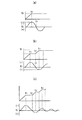
前記解析によるプログラム内容は図3(a)に示すように、ダム1の対象領域を幾つかの小ブロックに分割し、各ブロック毎に振れ止めを考慮して横行トロリー3の運転の速度、バケット6の昇降速度を定め、最短時間での運転パタ―ンを算定したもので、横行トロリーの運転速度Vxは図3(b)に示すようにスタート座標から加速し、次いで一定速度となり、次いで減速により目標座標で0となる運転パタ―ンが設定されている。バケット6の吊索5の昇降速度Vzは図3(c)に示すように横行トロリー3の運転パタ―ンに準じた運転パタ―ンに設定されている。
【0038】
主索2の撓み度合いは、主索2の張力と主索2に加わる全荷重によって異なる。しかしながら主索2の張力を計測し既知の値で一定とすれば、変数として荷重を入力することによって、前記プログラムによる運転時間,運転パタ―ンが定まる。また主索2,横行トロリー3,バケット6の荷重は既知の値であり、バケット6内に投入されるコンクリートの重量に応じて定まる。
【0039】
このコンクリートは、打設場所及び工種に応じてモルタル,中練りコンクリート,固練りコンクリートであり、バケット6の容量を一定とするとその比重に応じて異なってくる。バッチャープラントで製造されたコンクリートは搬送台車10によってバンカー線上に運ばれるとともに、その品種情報も操作室9側及びバケット6側にもたらされ、この情報を元に運転が実行される。
【0040】
制御部22は、バケット6の搬送に際し、バケット6の現在位置を搬送開始位置Aとして前記GPS受信機82を通じて取得する。そして、演算部24は、バケット6の現在位置と、指定された搬送終了位置Bとに基づき、所定のアルゴリズムに従って、複数の運転パターンの中から適切な運転パターンを1つ選出する。制御部22は、選出された運転パターンに従って、入力されたコンクリートの品種情報を元に各ウインチ7,8を駆動させて横行トロリー3を移動させながら、バケット6を搬送開始位置Aから搬送終了位置Bまで自動搬送する。
【0041】
横行トロリー3の加速時および減速時には、横行トロリー3に対するバケット6の速度の応答遅れにより振れが生じるため、この振れを相殺すべく、制御部22はフィードバック制御を行う。ここで、演算部24は、横行トロリー3およびバケット6の現在位置をこれらに搭載した各GPS受信機80,82でリアルタイムに逐次測位して、その測位結果に基づき、横行トロリー3の速度、並びにこの横行トロリー3に対するバケット6の振れ角度及びその角速度を算出する。具体的には、横行トロリー3の速度は、GPS受信機80より逐次取得した位置情報に基く変位量とその時間差から算出する。また、バケット6の振れ角度については、GPS受信機82より逐次取得した位置情報に基く変位量と変位方向から算出し、またバケット6の角速度についてはGPS受信機82より逐次取得した位置情報に基く変位量と時間差から算出する。演算部24はこれらの値をリアルタイムで算出する。そして、演算部24は、算出したこれら値を振れ止め用の所定の運動方程式に当てはめて振れ止め用の制御電圧を演算する。
【0042】
図4及び図5は加速時における制御手順と、制御内容に応じた速度とバケット6の振れの状態との関係を示すものである。図4に示すように、運転開始後、横行トロリー3の一段階の加速が終了した時点で、横行トロリー3の位置,速度、及びバケット6の振れ角度及び角速度の測位または検出が行われ、これらに基づき振れ止め用の制御電圧が算出されるとともに、制御開始時間が計算され、開始するまで制御待機状態となる(ステップ101〜107)。
【0043】
この状態は図5(a)に示すように、運転開始から横行トロリー3の速度が定速v1に至った時間をt1とすると、バケット6は応答遅れにより振れが生じ、振れ幅v2で示す左右に振れる振り子状の正弦曲線となり、その周期は吊索5の長さが一定なら一定であり、また最大振幅もその長さにより定まる。これに基づき、時刻t1以降にv2=0となるポイント時刻t2を求め、このポイントからv2=maxに該当する二段階目の加速を所定時間加えることにより振れが相殺されることになる。開始時間t2になったなら一次フィードバック制御を開始し、横行トロリー3に加速のための制御電圧を駆動装置34に与え、その結果の振れ具合を計測し、それ以後の振れ状態を演算する。その結果、許容値内であるならば、フィードバック制御を終了する(ステップ108,109)。
【0044】
時刻t3まで一次フィードバック制御がなされた状態は図5(b)に示される。この間(時刻t2〜t3間)におけるv2=max<許容値であるならばフィーバック制御を終了する。
【0045】
これに対し、許容値を超えていたのならば、前記と同様の手順により二次フィードバック開始時刻t4を計算し、開始時刻となった場合にはステップ109で出された制御電圧を三段階目の加速を所定時間加えるとともに、振れを計測する(ステップ110〜114)。
【0046】
二次フィードバック制御がなされた状態は図5(c)に示される。またこの間(時刻t3〜t4間)におけるv2=max<許容値であるならばフィーバック制御を終了するが、許容値を超えていたならば、許容値に収束するまで再度ステップ110に戻り同様のフィードバック制御を繰返す。なお、減速時における制御も同一であるが、制御方向が異なり、階段状の減速パタ―ンにより振れを相殺する。
【0047】
また、完全に振れが停止した位置は搬送開始位置Aまたは搬送終了位置Bの真上である事が望ましいが、フィードバック制御を掛けることにより実際の目標位置に対して横行トロリー3の行き足が足りなかったり、逆に行き過ぎる場合があるので、制御終了後は微速移動により位置修正し、バケット6を下ろせば搬送作業を終了する。
【0048】
往路においてバケット6を下ろす場合には、例えばバケット6及びホッパー11に設けた超音波エリアセンサ50,76で縦横の自動微調整作業を行い、補完する。この後、ホッパー11上に停止してゲートを開いてコンクリートを放出し、往路における全作業を終了する。
【0049】
また、復路においてバケット6を下ろす場合も同様に、フィードバック制御の後微調整によりバケット6はバンカー線の直上に至り、その後はバケット6及びバンカー線に備えられた超音波エリアセンサ50,44で縦横の自動微調整作業を行い、補完する。この後、バンカー線上に着底し、スイッチ42により確認されると再びコンクリート受け入れ待機状態となる。
【0050】
次に本発明にかかるケーブルクレーンの制御システムの第2実施形態について説明する。図6は、この発明にかかるケーブルクレーンの制御システムの第2実施形態を示したものである。ここでは、本発明の制御システムを軌索式ケーブルクレーンに採用した場合について示す。なお、ここでは、前記実施の形態と同一の構成要素には原則として同一の符号を付すとともに、前記実施の形態と同一の構成については説明を省き、前記実施の形態と異なる点を中心に説明する。
【0051】
この軌索式ケーブルクレーンは、山間の谷部にダム1をコンクリートを打設して構築すべく設けられたもので、ダム1の構築予定箇所を挟んだ一方の山側において2本の主塔90,91間に張設される軌索92と、この軌索92に沿って走行する走行トロリー93と、この走行トロリー93を牽引する走行索94と、走行トロリー93を軌索92に沿って移動させるべく走行索94を牽引する走行ウインチ97とを備える。主索2は、一端が走行トロリー93に連結され、他端がダム1を挟んだ他方の山側の固定塔95に連結され、これらの間に張設されている。この主索2と走行トロリー93との間には主索調整索96が介設され、主索調整ウインチ98により牽引されて主索2の撓みを調整する。この他、前記実施の形態と同様、横行トロリー3と、牽索4と、吊索5と、バケット6と、横行ウインチ7と、縦行ウインチ8とを備える。
【0052】
軌索92は、その一端が一方の主塔90に固定されるとともに、他端が他方の主塔91に軌索緊張装置(図示外)を介して固定され、これらの主塔90,91間に所定の緊張力で懸架されている。
【0053】
走行索94は、両端が2本の主塔90,91に各々固定され、走行ウインチにより牽引されることにより、走行トロリー95を軌索92に沿って両方向に任意に移動させる。走行索94は、その一端が主塔に対して走行索緊張装置(図示外)を介して固定されることにより、所定の緊張力を保持するようになっている。
【0054】
主索2は、その一端が主索調整装置に連結され、その他端が固定塔95に連結固定されていて、走行トロリー93と固定塔95との間に懸架されているとともに、走行トロリー93の移動に伴って固定塔95を中心とした略扇型の領域をカバーするように移動する。
【0055】
主索調整装置99は、複数の巻回プーリーを備え、この巻回プーリーに主索調整索96が順次巻回されている。主索調整索96は、主索調整ウィンチ98の回動によって主索調整装置99の長さを調整し、これによって、主索調整装置99の一端に取り付けた主索2の、走行トロリー93の移動による撓みの変動を調整するようになっている。
【0056】
固定塔95周辺に隣接して設置された操作室9には、各ウィンチ7,8,97,98の駆動制御装置や運点用操作卓、運転パターンを演算解析したりデータを保存するコンピュータからなる演算部、無線機などが設けられている。各ウインチ7,8,97,98は、各々、ドラム、モータ、ブレーキ、減速機、制御装置等を備え、操作室17の駆動制御装置からの指令によりドラムを回転駆動して、各索4,5,94,96を牽引する。
【0057】
GPS受信機は、横行トロリー3およびバケット6とともに、走行トロリー93と主索調整装置とに搭載されている。各GPS受信機は、横行トロリー3、走行トロリー93、バケット6、主索調整装置99の各々の現在位置座標を三次元座標としてリアルタイムに算出し、その算出結果をそれぞれ各無線機52,53等を通じて操作室9の制御部に送信する。
【0058】
演算部は、前記の場合と同様に、モデル化された多数の運転パターンのプログラムを記憶している。ただし、記憶している運転パターンは、搬送開始位置Aおよび搬送終了位置B、横行トロリー3の位置や主索調整装置索96と主索2との連結位置、主索調整装置99と走行トロリー93との連結位置、軌索92上における走行トロリー3の配設位置等の各接点における静的釣合い方程式から、バケット6の各位置に対応する走行索94の繰り出し長さ、主索調整索96の繰り出し長さ、牽索4の繰り出し長さ、吊索5の繰り出し長さ、及びこれらの索4,5,94,96の繰り出し速度を算定要素として、また振子の運動方程式に基づいて、搬送開始位置であるバンカー部20や、搬送終了位置であるコンクリートの打設箇所などのバケット6の各停止位置においてバケット6が振れを生じないようにするための、走行索94、主索調整索96、牽索4、及び吊索5の繰り出し速度の組み合わせが解析されることから、これらの解析結果からモデル化されている。演算部は、ケーブルクレーンを運転する際に、設定条件に応じて前記モデル化された運転パターンを選択して、目標地点まで走行索5、主索調整索8、牽索10、及び吊索11の繰り出しを時間関数として計算してこれをコンピュータのメモリに保存する。
【0059】
演算部は、このメモリに保存した運転パターンの情報に基づき、走行ウィンチ97,主索調整ウィンチ96、横行ウインチ7、及び縦行ウインチ8の制御装置に指示を与え、各ウィンチ7,8,96,97による繰り出し速度を制御して、スタート位置から目標位置まで、振れ止めを考慮した自動運転を行なう。このとき、演算部は、各GPS受信機を通じて横行トロリー3やバケット6、走行トロリー93、主索調整装置99の各現在位置をリアルタイムに逐次測位して、バケット6が予定通り所定の運転パターンに沿って移動しているかどうか逐次監視する。なお、コンクリートの打設位置からバンカー部20に至る復路においては、走行トロリー93を動かさないような運転パターンにしてもよい。
【0060】
ここで、演算部は、横行トロリー3の加速時、減速時、停止時において、横行トロリー3に対するバケット6の振れを相殺するために、例えば特開平11−35281号等に開示されるような周知のファジー推論によるフィードバック制御を行う。具体的には、「吊索の長さ」、「横行トロリーの速度」、「バケットの振れ角」、「振れ方向」、「減速開始位置からのズレ」、「停止後・加速後の振れ(停止または加速度どの程度の振れ幅であるかを示す)」、「停止位置のずれ(バケットが停止した時、目標位置からどの程度ずれたかを示すもの)」などの要素についてそれぞれファジー推論の内容と実測値とを対応させたメンバーシップ関数を定義する。
【0061】
演算部は、横行トロリー3の加速時及び減速時においては、各GPS受信機を通じて横行トロリー3およびバケット6の現在位置をリアルタイムに逐次測位し、その測位結果に基づき、横行トロリー3の速度、並びにこの横行トロリー3に対するバケット6の振れ角度及びその角速度を算出し、その算出結果を予め定義したメンバーシップ関数に入力し、バケット6の振れを相殺するための適切なフィードバック制御を推論し、これを実行する。横行トロリー3の速度、並びに横行トロリー3に対するバケット6の振れ角度及びその角速度については、前述した方法で算出する。
【0062】
なお、ここでは、横行トロリー3の加速時には前記バケット6の振れ角と振れ方向及び横行トロリー3の速度を入力することにより行い、横行トロリー3の減速時にはバケット6の振れ角と振れ方向及び横行トロリー3の速度と位置を入力することにより行い、横行トロリー3の停止時にはバケット6の振れ角と振れ方向及び横行トロリー3の速度と位置を入力することにより行う。
【0063】
このようにバケット6の振れを相殺するための制御をファジー推論により行うことで、迅速かつ円滑な自動運転が可能になるとともに、搬送終了位置での精度の良い位置決め作業が容易になされることになる。
【0064】
===他の実施の形態===
(1)前記速度検出器7e,8e、前記エンコーダX,Zおよび前記光波測距計30については、GPS受信機が何らかの不具合により測位不能に陥ったときに、横行トロリーやバケットの位置検出に使用する。
【0065】
(2)本発明にあっては、前述したタイプのケーブルクレーン以外に他のタイプのケーブルクレーン、例えば並行移動式や弧動式のケーブルクレーン等において適用することができる。
【0066】
(3)図1に示すケーブルクレーンの制御システムにおいては、特許第2684939号に開示される周知なファージー推論による制御を行ってもよく、また、図6に示す軌索式ケーブルクレーンの制御システムにおいては、特開平11−35280号に開示されるようなバケットの振れ止め制御を行ってもかまわない。
【0067】
【発明の効果】
本発明にかかる第1および第2ケーブルクレーンの制御システムによれば、バケットや横行トロリー等にそれぞれGPS受信機を搭載し、これらのGPS受信機を通じて横行トロリーやバケット等の現在位置を測位することで、従来のように主索や牽索、吊索等のワイヤーの伸びや滑り、天候等の悪影響を受けずに済むとともに、計測速度が速くなり精度も向上する。
【0068】
また、前記バケットの搬送開始位置および搬送終了位置、主索の撓み具合、主索の撓み度合い、牽索の繰り出し長さ、吊索の繰り出し長さ、走行索の繰り出し長さ、主索調整索の繰り出し長さに基づき、主索や横行トロリー、バケット、軌索の挙動を予め解析して得られた多数のモデル化した運転パターンの中から、GPS受信機を通じて検出される前記バケットと横行トロリーとの現在位置情報に応じて、適切な運転パターンを選択してその運動パターンに従って前記バケットを搬送すべく前記各ウインチを駆動制御することで、バケットを迅速に精度良くかつ短時間に目的地まで到達させることができ、バケットの搬送効率の可及的な向上を図ることができる。
【0069】
また、横行トロリーの加速時または減速時においては、横行トロリーの速度並びにバケットの振れ角度および角速度を精確に算出して、適切なタイミングでかつ適切なフィードバック量で制御を行うことができ、バケットの振れを十分に相殺することができる。
【0070】
また、第2のケーブルクレーンの制御システムにあっては、軌索、走行索、主索調整索、主索、牽索、及び吊索を懸垂曲線と仮定して、軌索、主索、横行トロリー及びバケットの挙動を解析して運転パターンをモデル化したことで、より正確な位置決めや振れ止めを行うことができる。
【0071】
さらに、このシステムでは、横行トロリーの加速時および減速時において行うバケットの振れを相殺するための制御を、横行トロリーを同方向に階段状に加速あるいは減速することにより行うことで、横行トロリーやバケットに限らずケーブルクレーン全体に不要な負荷を与えることなく効率的に振れを相殺することができる。
【0072】
また、前記横行トロリーの加速時および減速時において行うバケットの振れを相殺するための制御をファジー推論により行うことで、迅速かつ円滑な自動運転が可能になるとともに、搬送終了位置での精度の良い位置決め作業が容易に行える。
【0073】
ここで、前記横行トロリーの加速時及び減速時におけるファジー推論によるフィードバック制御が、加速時には前記バケットの振れ角と振れ方向及び前記横行トロリーの速度を入力することにより行われ、減速時には前記バケットの振れ角と振れ方向及び前記横行トロリーの速度と位置を入力することにより行われ、さらに停止時には前記バケットの振れ角と振れ方向及び前記横行トロリーの速度と位置を入力することにより行われることで、各タイミングに応じた適切な制御を行うことができる。
【図面の簡単な説明】
【図1】本発明にかかるケーブルクレーンの制御システムの一実施形態を示した全体説明図である。
【図2】本発明にかかるケーブルクレーンの制御システムのシステム構成の一実施形態を示したブロック構成図である。
【図3】本発明にかかるケーブルクレーンの制御システムのバケット搬送制御方法を示す説明図である。
【図4】本発明にかかるケーブルクレーンの制御システムのバケットの加速時の処理手順の一例を示したフローチャートである。
【図5】本発明にかかるケーブルクレーンの制御システムにおけるバケット加速時の振れと速度との関係を示した説明図である。
【図6】本発明にかかるケーブルクレーンの制御システムを軌索式ケーブルクレーンに適用した場合の一実施形態を示す全体説明図である。
【図7】従来のケーブルクレーンの制御システムの一例を示す説明図である。
【符号の説明】
1 ダム 90,91 主塔
2 主索 92 軌索
3 横行トロリー 93 走行トロリー
4 牽索 94 走行索
5 吊索 95 固定塔
6 コンクリートバケット 96 主索調整索
7 横行ウインチ 97 走行ウィンチ
8 縦行ウインチ 98 主索調整ウィンチ
22 制御部 99 主索調整装置
34,36 駆動制御装置
80,82 GPS受信機
84 人工衛星[0001]
BACKGROUND OF THE INVENTION
The present invention relates to a control system for a cable crane installed to convey various materials such as concrete at a construction site of a dam, for example.
[0002]
[Prior art]
As is well known, for example, in a dam construction site, a cable crane is used as one of means for transporting concrete from a production site to a placement site. Conventionally, as shown in FIG. 7, the cable crane has a
[0003]
A
[0004]
Since this type of structure requires a large amount of concrete, it is transported along an oblique trajectory as shown in the figure in order to reduce the transport time per
[0005]
At the time of acceleration or deceleration of the traversing
[0006]
[Problems to be solved by the invention]
By the way, when such a cable crane is used for a long period of time, wires such as the check rope 4 and the
[0007]
In order to compensate for this, optical ranging is performed by a total station. However, in this system, when fog or the like occurs, the position of the traversing
[0008]
The present invention has been made in view of such circumstances, and its purpose is to accurately detect the current position of a traversing trolley or a bucket without being affected by the elongation or slipping of wires, weather, or the like. Another object of the present invention is to provide a cable crane control system capable of sufficiently canceling bucket runout.
[0009]
[Means for Solving the Problems]
In order to achieve such an object, in the present invention, a cable crane control system is configured as follows.
[0015]
(1) A trajectory stretched between two points on one side of a structure to be constructed such as a dam, a traveling trolley that can travel along the trajectory, a traveling rope for towing the traveling trolley, and one end of the traveling trolley. A main rope that is connected to the traveling trolley via a rope adjusting device, the other end of which is connected to the other fixed tower with the dam interposed therebetween, and is stretched between them, and a traverse that can travel along the main rope A trolley, a check for pulling the traversing trolley, a bucket suspended below the traversing trolley via a suspension cable, and pulling the traveling cable to reciprocate the traveling trolley along the trajectory A traveling winch, a main rope adjusting winch that pulls the main rope adjusting rope of the main rope adjusting device to adjust the deflection of the main rope, and pulls the check rope to reciprocate the traversing trolley along the main rope. Wind up and down the traverse winch and the suspension rope to pull the bucket In a cable-type cable crane having a longitudinal winch to be lowered and a winch control device capable of individually driving and controlling each winch, a cable crane used when moving the bucket from a transfer start position to a transfer end position In the control system, a GPS receiver is mounted on each of the bucket, the traversing trolley, the traveling trolley, and the main rope adjusting device, and the bucket, the traversing trolley, the traveling trolley, and the The current position of the main rope adjustment device is sequentially measured.
[0016]
In this system, GPS receivers are installed in the traverse trolley, bucket, travel trolley, and main rope adjustment device, respectively. Accurate positioning without any adverse effects. Also, the measurement speed can be increased.
[0017]
(2) In this system, the winch control device includes the transport start position and the transport end position, the traveling length of the traveling rope, the feeding length of the main rope adjusting rope, the feeding length of the check rope, and the suspension A number of operation patterns that are pre-analyzed and modeled by analyzing the behavior of the trajectory, the main rope, the traversing trolley, and the bucket, using the feeding length of the rope and the feeding speed thereof as calculation elements, When the bucket moves, the current position of the bucket is measured through the GPS receiver, an appropriate driving pattern is selected from the driving patterns based on the positioning result, and the bucket is transported according to the driving pattern. Accordingly, the winch is driven and controlled.
[0018]
As a result, the bucket can be moved quickly and efficiently in accordance with a predetermined operation pattern, the control load is reduced and the responsiveness is improved, so that the bucket can be moved to the destination in a short time.
[0019]
(3) Here, for the driving pattern, assuming that the trajectory, the traveling rope, the main rope adjustment rope, the main rope, the check rope, and the suspension rope are suspension curves, the trajectory, the main rope, The behavior of the trolley and the bucket is analyzed and modeled. Thereby, accurate positioning and steadying can be performed, which is preferable.
[0020]
(4) At the time of acceleration or deceleration of the traversing trolley, the speed of the traversing trolley and the swing behavior of the bucket are detected based on the current position of the bucket and the traversing trolley that are measured through the GPS receiver. The winches are driven and controlled so as to cancel each other. As a result, at the time of acceleration or deceleration of the traversing trolley, the speed of the traversing trolley and the swing angle and angular velocity of the bucket are accurately calculated based on the measured position information of the traversing trolley and the bucket, and at an appropriate timing. The traverse trolley and bucket can be controlled with an appropriate amount of feedback.
[0021]
(5) The control for canceling the shake of the bucket performed when the traversing trolley is accelerated and decelerated is performed by accelerating or decelerating the trolley stepwise in the same direction. Thereby, it is possible to effectively cancel out the vibration without applying an unnecessary load to the entire cable crane, not limited to the traversing trolley and the bucket.
[0022]
(6) A control for canceling the shake of the bucket performed during acceleration and deceleration of the traversing trolley is performed by fuzzy inference. As a result, a quick and smooth automatic operation is possible, and an accurate positioning operation at the transfer end position is easily performed.
[0023]
(7) Feedback control by fuzzy inference during acceleration and deceleration of the traversing trolley is performed by inputting the bucket swing angle and swing direction and the speed of the traversing trolley during acceleration, and the bucket swing angle and swing during deceleration. This is performed by inputting the direction and the speed and position of the traversing trolley, and further by inputting the swing angle and direction of the bucket and the speed and position of the traversing trolley when stopped. Thereby, appropriate control according to each timing can be performed.
[0024]
DETAILED DESCRIPTION OF THE INVENTION
Embodiments of a cable crane control system according to the present invention will be described below with reference to the accompanying drawings. 1 and 2 show a first embodiment of a cable crane control system according to the present invention. FIG. 1 is a schematic diagram showing the overall configuration of the present invention, and FIG. 2 is a block diagram showing the system configuration. In this embodiment, parts that are the same as or correspond to those in the prior art are given the same reference numerals.
[0025]
The cable crane basically has a
[0026]
A
[0027]
In the
[0028]
An inclination
[0029]
The
[0030]
Each
[0031]
The
[0032]
A
[0033]
Below the
[0034]
The
[0035]
By the way, the
[0036]
The
[0037]
As shown in FIG. 3 (a), the program content by the above analysis divides the target area of the
[0038]
The degree of bending of the
[0039]
This concrete is mortar, medium-mixed concrete, or solid-mixed concrete according to the placement site and the type of work, and varies depending on the specific gravity when the capacity of the
[0040]
When the
[0041]
At the time of acceleration and deceleration of the traversing
[0042]
4 and 5 show the control procedure at the time of acceleration, and the relationship between the speed according to the control content and the swing state of the
[0043]
In this state, as shown in FIG. 5A, the speed of the traversing
[0044]
Time t 3 The state where the primary feedback control has been performed is shown in FIG. During this time (time t 2 ~ T 3 V) 2 If = max <allowable value, the feedback control is terminated.
[0045]
On the other hand, if the allowable value is exceeded, the secondary feedback start time t is performed by the same procedure as described above. 4 When the start time is reached, the control voltage output in step 109 is subjected to a third stage of acceleration for a predetermined time and the shake is measured (
[0046]
The state where the secondary feedback control is performed is shown in FIG. During this time (time t 3 ~ T 4 V) 2 If = max <allowable value, the feedback control is terminated, but if the allowance value is exceeded, the process returns to step 110 until it converges to the acceptable value, and the same feedback control is repeated. The control at the time of deceleration is the same, but the control direction is different, and the shake is canceled out by a step-like deceleration pattern.
[0047]
In addition, it is desirable that the position at which the shaking completely stops is immediately above the transport start position A or the transport end position B, but the travel of the traversing
[0048]
When the
[0049]
Similarly, when the
[0050]
Next, a second embodiment of the cable crane control system according to the present invention will be described. FIG. 6 shows a second embodiment of the cable crane control system according to the present invention. Here, it shows about the case where the control system of this invention is employ | adopted as a rail-type cable crane. Here, in principle, the same components as those in the above-described embodiment are denoted by the same reference numerals, and description of the same components as those in the above-described embodiment is omitted, and description is focused on differences from the above-described embodiments. To do.
[0051]
This cable-type cable crane is provided to construct a
[0052]
One end of the
[0053]
The traveling
[0054]
One end of the
[0055]
The main
[0056]
The
[0057]
The GPS receiver is mounted on the traveling
[0058]
As in the case described above, the calculation unit stores a number of modeled operation pattern programs. However, the stored operation patterns are the transfer start position A and the transfer end position B, the position of the traversing
[0059]
Based on the driving pattern information stored in the memory, the arithmetic unit gives instructions to the control devices for the traveling
[0060]
Here, the arithmetic unit is well known as disclosed in, for example, Japanese Patent Application Laid-Open No. 11-35281 in order to cancel out the swing of the
[0061]
When the traversing
[0062]
Here, when the traversing
[0063]
Thus, by performing control for canceling the shake of the
[0064]
=== Other Embodiments ===
(1) The
[0065]
(2) The present invention can be applied to other types of cable cranes other than the above-described type of cable cranes, such as parallel movement type and arc type cable cranes.
[0066]
(3) In the control system of the cable crane shown in FIG. 1, the control by the well-known phage reasoning disclosed in Japanese Patent No. 2684939 may be performed. In the control system of the cable type cable crane shown in FIG. May be performed to control the steadying of the bucket as disclosed in JP-A-11-35280.
[0067]
【The invention's effect】
According to the control system of the first and second cable cranes according to the present invention, GPS receivers are mounted on buckets, traversing trolleys, etc., and the current positions of traversing trolleys, buckets, etc. are measured through these GPS receivers. Thus, as in the conventional case, it is not necessary to be adversely affected by the elongation and slipping of the wires such as the main rope, the check rope, and the suspension rope, and the weather, and the measurement speed is increased and the accuracy is improved.
[0068]
In addition, the transfer start position and transfer end position of the bucket, the degree of bending of the main rope, the degree of bending of the main rope, the extension length of the check rope, the extension length of the suspension rope, the extension length of the running rope, the main rope adjustment rope The bucket and traversing trolley detected through the GPS receiver from a number of modeled driving patterns obtained by analyzing the behavior of the main rope, traversing trolley, bucket, and trajectory in advance based on the payout length of By selecting an appropriate driving pattern according to the current position information and driving and controlling each winch so as to transport the bucket according to the movement pattern, the bucket can be quickly and accurately reached the destination in a short time. Therefore, it is possible to improve the bucket transport efficiency as much as possible.
[0069]
In addition, at the time of acceleration or deceleration of the transverse trolley, the speed of the transverse trolley and the swing angle and angular velocity of the bucket can be accurately calculated, and control can be performed at an appropriate timing and with an appropriate feedback amount. The shake can be canceled out sufficiently.
[0070]
In the control system of the second cable crane, the trajectory, the main rope, the traverse, assuming that the trajectory, the traveling rope, the main rope adjustment rope, the main rope, the check rope, and the suspension rope are suspension curves. By analyzing the behavior of the trolley and bucket and modeling the operation pattern, more accurate positioning and steadying can be performed.
[0071]
Furthermore, in this system, the control for canceling the shake of the bucket performed during acceleration and deceleration of the traversing trolley is performed by accelerating or decelerating the traversing trolley stepwise in the same direction. In addition to the above, it is possible to effectively cancel out the vibration without giving unnecessary load to the entire cable crane.
[0072]
In addition, by performing control for canceling the shake of the bucket at the time of acceleration and deceleration of the traversing trolley by fuzzy inference, quick and smooth automatic operation becomes possible, and accuracy at the conveyance end position is good. Positioning work can be done easily.
[0073]
Here, feedback control based on fuzzy inference during acceleration and deceleration of the traversing trolley is performed by inputting a swing angle and a swing direction of the bucket and a speed of the traversing trolley during acceleration, and the swing of the bucket during deceleration. It is performed by inputting the angle and swing direction and the speed and position of the traversing trolley, and further by inputting the swing angle and swing direction of the bucket and the speed and position of the traversing trolley when stopping, Appropriate control according to timing can be performed.
[Brief description of the drawings]
FIG. 1 is an overall explanatory view showing an embodiment of a cable crane control system according to the present invention.
FIG. 2 is a block diagram showing an embodiment of a system configuration of a cable crane control system according to the present invention.
FIG. 3 is an explanatory diagram showing a bucket conveyance control method of the cable crane control system according to the present invention.
FIG. 4 is a flowchart showing an example of a processing procedure when accelerating a bucket in the control system for the cable crane according to the present invention.
FIG. 5 is an explanatory diagram showing the relationship between runout and speed during bucket acceleration in the cable crane control system according to the present invention.
FIG. 6 is an overall explanatory view showing an embodiment when the cable crane control system according to the present invention is applied to a rail cable crane.
FIG. 7 is an explanatory diagram showing an example of a conventional cable crane control system.
[Explanation of symbols]
1
2
3 Traversing
4 Checking 94 Driving cable
5
6
7
8 Longitudinal winches 98 Main rope adjustment winch
22
34, 36 Drive control device
80,82 GPS receiver
84 Satellite
Claims (7)
Priority Applications (1)
| Application Number | Priority Date | Filing Date | Title |
|---|---|---|---|
| JP2000058516A JP3669242B2 (en) | 2000-03-03 | 2000-03-03 | Cable crane control system |
Applications Claiming Priority (1)
| Application Number | Priority Date | Filing Date | Title |
|---|---|---|---|
| JP2000058516A JP3669242B2 (en) | 2000-03-03 | 2000-03-03 | Cable crane control system |
Publications (2)
| Publication Number | Publication Date |
|---|---|
| JP2001240372A JP2001240372A (en) | 2001-09-04 |
| JP3669242B2 true JP3669242B2 (en) | 2005-07-06 |
Family
ID=18579099
Family Applications (1)
| Application Number | Title | Priority Date | Filing Date |
|---|---|---|---|
| JP2000058516A Expired - Fee Related JP3669242B2 (en) | 2000-03-03 | 2000-03-03 | Cable crane control system |
Country Status (1)
| Country | Link |
|---|---|
| JP (1) | JP3669242B2 (en) |
Families Citing this family (16)
| Publication number | Priority date | Publication date | Assignee | Title |
|---|---|---|---|---|
| CN1132777C (en) | 2001-06-13 | 2003-12-31 | 上海振华港口机械股份有限公司 | Hanger without electric cable |
| CN1185155C (en) * | 2001-12-12 | 2005-01-19 | 上海振华港口机械股份有限公司 | Satellite positioning system mobile station for wheeled gantry container crane |
| US7032763B1 (en) * | 2002-11-18 | 2006-04-25 | Mi-Jack Products, Inc. | System and method for automatically guiding a gantry crane |
| CN100545076C (en) | 2003-07-30 | 2009-09-30 | 上海振华重工(集团)股份有限公司 | Container crane capable of lifting dual 40 feet box |
| US7289875B2 (en) * | 2003-11-14 | 2007-10-30 | Siemens Technology-To-Business Center Llc | Systems and methods for sway control |
| CN100375711C (en) | 2005-04-06 | 2008-03-19 | 上海振华港口机械(集团)股份有限公司 | Four winding drum differential lifting mechanism of bi 40 feet shoreside container crane |
| CN100375710C (en) | 2005-04-06 | 2008-03-19 | 上海振华港口机械(集团)股份有限公司 | Two winding drum differential lifting mechanism of bi 40 feet shoreside container crane |
| CN2811252Y (en) | 2005-04-06 | 2006-08-30 | 上海振华港口机械(集团)股份有限公司 | Dual lifting mechanism for bis-40' quayside container crane |
| CN100545065C (en) | 2006-04-20 | 2009-09-30 | 上海振华重工(集团)股份有限公司 | Container wharf arrangement and loading and unloading flow process |
| CN101229883A (en) | 2008-01-24 | 2008-07-30 | 上海振华港口机械(集团)股份有限公司 | Container terminal loading and unloading system |
| JP6280380B2 (en) * | 2014-02-05 | 2018-02-14 | Ihi運搬機械株式会社 | Crane hanging load deflection angle detector |
| CN104401878B (en) * | 2014-10-29 | 2016-02-24 | 北京机械设备研究所 | A kind of multiaxis composite flooding tower machine control method |
| JP6654804B2 (en) * | 2015-03-02 | 2020-02-26 | イワフジ工業株式会社 | Cableway transport device |
| CN106904533B (en) * | 2017-04-10 | 2018-01-19 | 三峡大学 | A kind of cage antiswing device being used for during cable machine cage puts in storage and method |
| JP2019119577A (en) * | 2018-01-10 | 2019-07-22 | Ihi運搬機械株式会社 | Runaway prevention device of rail machine |
| CN114084855A (en) * | 2021-10-09 | 2022-02-25 | 四川美术学院 | Ruins search and rescue automation platform |
-
2000
- 2000-03-03 JP JP2000058516A patent/JP3669242B2/en not_active Expired - Fee Related
Also Published As
| Publication number | Publication date |
|---|---|
| JP2001240372A (en) | 2001-09-04 |
Similar Documents
| Publication | Publication Date | Title |
|---|---|---|
| JP3669242B2 (en) | Cable crane control system | |
| US5392935A (en) | Control system for cable crane | |
| JP2512854B2 (en) | Control system for the cavern lane | |
| JP3659117B2 (en) | Cable crane bucket control system | |
| JP4848416B2 (en) | Cable reel control device, cable reel control method, and tire crane | |
| JP2684939B2 (en) | Control method of cable crane | |
| JP2684938B2 (en) | Control method of cable crane | |
| JP2577127B2 (en) | Bucket for cable crane | |
| JP4131092B2 (en) | Cable crane automatic control method and program | |
| JPH1135280A (en) | Control method of rail rope cable crane | |
| JP2684940B2 (en) | Control method of cable crane | |
| JPH1135279A (en) | Control method of rail rope cable crane | |
| JPH1135281A (en) | Control method of rail rope cable crane | |
| JPH1160158A (en) | Control method of parallel running type cable crane | |
| JP2022154200A (en) | Control device, track-type cable crane, program and construction method of concrete structure | |
| JP2020059579A (en) | Bridge cargo handling apparatus | |
| JPH1179660A (en) | Control method for arc-moving type cable crane | |
| JP3636518B2 (en) | Rail cable crane | |
| JPH1160159A (en) | Control method of parallel running type cable crane | |
| JPH1179661A (en) | Control method for arc-moving type cable crane | |
| JP2556244B2 (en) | Coordinate correction method of trolley in cable crane | |
| JP3242633B2 (en) | How to set operation pattern of suspended load suspended by cable crane | |
| JP3173752B2 (en) | Automatic operation of crane | |
| JP2003002579A (en) | Method of controlling cable crane automatically, and program | |
| JPH1179662A (en) | Control method for arc-moving type cable crane |
Legal Events
| Date | Code | Title | Description |
|---|---|---|---|
| A977 | Report on retrieval |
Free format text: JAPANESE INTERMEDIATE CODE: A971007 Effective date: 20040713 |
|
| A131 | Notification of reasons for refusal |
Free format text: JAPANESE INTERMEDIATE CODE: A131 Effective date: 20040720 |
|
| RD04 | Notification of resignation of power of attorney |
Free format text: JAPANESE INTERMEDIATE CODE: A7424 Effective date: 20040922 |
|
| A02 | Decision of refusal |
Free format text: JAPANESE INTERMEDIATE CODE: A02 Effective date: 20050104 |
|
| A521 | Written amendment |
Free format text: JAPANESE INTERMEDIATE CODE: A523 Effective date: 20050224 |
|
| A911 | Transfer of reconsideration by examiner before appeal (zenchi) |
Free format text: JAPANESE INTERMEDIATE CODE: A911 Effective date: 20050301 |
|
| TRDD | Decision of grant or rejection written | ||
| A01 | Written decision to grant a patent or to grant a registration (utility model) |
Free format text: JAPANESE INTERMEDIATE CODE: A01 Effective date: 20050322 |
|
| A61 | First payment of annual fees (during grant procedure) |
Free format text: JAPANESE INTERMEDIATE CODE: A61 Effective date: 20050404 |
|
| R150 | Certificate of patent or registration of utility model |
Free format text: JAPANESE INTERMEDIATE CODE: R150 |
|
| FPAY | Renewal fee payment (event date is renewal date of database) |
Free format text: PAYMENT UNTIL: 20080422 Year of fee payment: 3 |
|
| FPAY | Renewal fee payment (event date is renewal date of database) |
Free format text: PAYMENT UNTIL: 20090422 Year of fee payment: 4 |
|
| FPAY | Renewal fee payment (event date is renewal date of database) |
Free format text: PAYMENT UNTIL: 20100422 Year of fee payment: 5 |
|
| FPAY | Renewal fee payment (event date is renewal date of database) |
Free format text: PAYMENT UNTIL: 20100422 Year of fee payment: 5 |
|
| FPAY | Renewal fee payment (event date is renewal date of database) |
Free format text: PAYMENT UNTIL: 20110422 Year of fee payment: 6 |
|
| S531 | Written request for registration of change of domicile |
Free format text: JAPANESE INTERMEDIATE CODE: R313531 |
|
| FPAY | Renewal fee payment (event date is renewal date of database) |
Free format text: PAYMENT UNTIL: 20110422 Year of fee payment: 6 |
|
| R350 | Written notification of registration of transfer |
Free format text: JAPANESE INTERMEDIATE CODE: R350 |
|
| FPAY | Renewal fee payment (event date is renewal date of database) |
Free format text: PAYMENT UNTIL: 20110422 Year of fee payment: 6 |
|
| FPAY | Renewal fee payment (event date is renewal date of database) |
Free format text: PAYMENT UNTIL: 20120422 Year of fee payment: 7 |
|
| FPAY | Renewal fee payment (event date is renewal date of database) |
Free format text: PAYMENT UNTIL: 20120422 Year of fee payment: 7 |
|
| FPAY | Renewal fee payment (event date is renewal date of database) |
Free format text: PAYMENT UNTIL: 20130422 Year of fee payment: 8 |
|
| FPAY | Renewal fee payment (event date is renewal date of database) |
Free format text: PAYMENT UNTIL: 20130422 Year of fee payment: 8 |
|
| FPAY | Renewal fee payment (event date is renewal date of database) |
Free format text: PAYMENT UNTIL: 20140422 Year of fee payment: 9 |
|
| LAPS | Cancellation because of no payment of annual fees |