JP3666342B2 - Travel control device - Google Patents
Travel control device Download PDFInfo
- Publication number
- JP3666342B2 JP3666342B2 JP2000043398A JP2000043398A JP3666342B2 JP 3666342 B2 JP3666342 B2 JP 3666342B2 JP 2000043398 A JP2000043398 A JP 2000043398A JP 2000043398 A JP2000043398 A JP 2000043398A JP 3666342 B2 JP3666342 B2 JP 3666342B2
- Authority
- JP
- Japan
- Prior art keywords
- brake
- preload
- control
- vehicle
- brake preload
- Prior art date
- Legal status (The legal status is an assumption and is not a legal conclusion. Google has not performed a legal analysis and makes no representation as to the accuracy of the status listed.)
- Expired - Lifetime
Links
Images


Classifications
-
- B—PERFORMING OPERATIONS; TRANSPORTING
- B60—VEHICLES IN GENERAL
- B60K—ARRANGEMENT OR MOUNTING OF PROPULSION UNITS OR OF TRANSMISSIONS IN VEHICLES; ARRANGEMENT OR MOUNTING OF PLURAL DIVERSE PRIME-MOVERS IN VEHICLES; AUXILIARY DRIVES FOR VEHICLES; INSTRUMENTATION OR DASHBOARDS FOR VEHICLES; ARRANGEMENTS IN CONNECTION WITH COOLING, AIR INTAKE, GAS EXHAUST OR FUEL SUPPLY OF PROPULSION UNITS IN VEHICLES
- B60K31/00—Vehicle fittings, acting on a single sub-unit only, for automatically controlling vehicle speed, i.e. preventing speed from exceeding an arbitrarily established velocity or maintaining speed at a particular velocity, as selected by the vehicle operator
- B60K31/0008—Vehicle fittings, acting on a single sub-unit only, for automatically controlling vehicle speed, i.e. preventing speed from exceeding an arbitrarily established velocity or maintaining speed at a particular velocity, as selected by the vehicle operator including means for detecting potential obstacles in vehicle path
Description
【0001】
【発明の属する技術分野】
この発明は、前方制動対象物を検知したときにブレーキ予圧を必要とする要ブレーキ予圧状態である場合にブレーキ予圧を発生させるブレーキ制御手段と、追従走行対象車両との間の車間距離を目標車間距離に維持するように追従走行制御する追従走行制御手段とを備えた走行制御装置に関する。
【0002】
【従来の技術】
従来の走行制御装置のうちブレーキ制御に関しては、例えば特開平7−144588号公報に記載の技術のように、前方障害物と自車との車間距離が所定の安全距離に満たない場合に追突を未然に防ぐ様に自動ブレーキ制御を行う車両追突防止装置や、特開平6−24302号公報記載の技術のように、運転者の違いによるアクセル情報を踵止めに載せた運転者の足の踵を検出する踵検出手段等により検知して、ブレーキ操作前に予備制動を行う自動予備制動システム等が知られており、追従走行制御に関しては、例えば特開平10−114237号公報に記載の技術のように、追従走行制御時に運転者が追い越しのためにアクセルペダルを踏込み加速レーンチェンジをしようしたときに、追従制御を解除して運転者の意志に従った走行を行う追従走行制御装置が知られている。
【0003】
【発明が解決しようとする課題】
しかしながら、走行制御装置で、上記ブレーキ制御機能と追従走行制御機能との双方を備えた場合には、制動対象物に急接近してブレーキ制御機能が作動した後に、運転者が追従走行制御機能を作動させるために開始操作を行った場合に、基本的にはブレーキ制御機能が作動しているくらい制動対象物と接近しているはずであるが、後述するように追従走行制御機能における判断で加速要求即ちエンジン出力を増加させる加速制御を選択するケースが考えられる。この場合、ブレーキ制御機能によるブレーキ制御に相対してエンジン出力が増大されることになるが、ブレーキ制御が行われており、車輪に制動力が作用している分だけエンジン出力が多めに指示される結果、スロットルバルブが必要以上に開いてしまい、その後ブレーキ制御機能のブレーキ制御が終了したときに、オーバートルクとなり加減速ハンチングを生じて、運転者に違和感を与えるという未解決の課題がある。
【0004】
ここで、ブレーキ制御機能による制動と追従走行制御機能による駆動との相反する状態が生じる要因としては、例えばブレーキ制御機能では、制動時の空走距離を短縮するためにブレーキ予圧を発生することが考えられ、この場合のブレーキ予圧の解除条件として、車間距離センサの精度に起因する車間距離検出値の変動によってブレーキ予圧状態が不必要に解除されることを防止するために、減速度が設定値以下となることを解除条件とすることなくブレーキ予圧状態となってからの経過時間が設定時間以上となったときにブレーキ予圧を解除することが考えられるが、このように減速度が設定値以下となる解除条件に代えてブレーキ予圧の解除条件をブレーキ予圧状態となってからの経過時間が設定時間以上となったときに設定すると、この経過時間設定時間に達する前に先行車が加速状態となったときや先行車が隣接レーンに車線変更するか又は自車両が車線変更して車間距離センサで近接した先行車を捕捉しない状態となったときに、追従走行制御機能では車間距離が大きくなることにより加速要求が発生する。また、ブレーキ制御機能と追従走行制御機能とで異なる外界認識センサを使用している場合に、ブレーキ制御機能のセンサでは先行車を捕捉してブレーキ予圧を発生するが、追従走行制御機能のセンサでは先行車を見失った状態となって設定車速まで加速する加速要求が発生する場合もある。さらに、ブレーキ制御では、車両前方に低速で走行している制動対象車両を検知して要ブレーキ予圧状態と判断しているが、運転者は隣接走行レーンが開いており、制動対象車両を追い越すことが可能であると判断した場合には、アクセルペダルを踏込んで加速状態としながら車線変更を行うことにより、車線変更の途中でブレーキ制御機能で制動対象車両を検知しなくなるまでは、ブレーキ予圧状態が継続されることが挙げられる。
【0005】
そこで、本発明は、上記従来例の未解決の課題に着目してなされたものであり、ブレーキ予圧発生状態で追従走行制御手段で加速要求が発生したときにブレーキ予圧の発生状態で加速操作が行われることを回避して運転者に違和感を与えることがない走行制御装置を提供することを目的としている。
【0006】
【課題を解決するための手段】
上記目的を達成するために、請求項1に係る走行制御装置は、車両前方の制動対象物に対する相対距離を検出する制動対象物検出手段を有し、該制動対象物検出手段で検出した制動対象物に対する相対距離に基づいてブレーキ予圧を必要とする要ブレーキ予圧状態であるか否かを判定し、要ブレーキ予圧状態である場合に、運転者がブレーキペダルを踏込んだときに高応答性をもって空走距離を短くできるブレーキ予圧を発生させるブレーキ制御手段と、制御開始操作に従って車両前方の追従走行対象車両との間の車間距離を目標車間距離に維持するように駆動力及び/又は制動力を制御して追従走行制御する追従走行制御手段とを備えた走行制御装置において、前記ブレーキ制御手段がブレーキ予圧を発生されているブレーキ予圧状態で、前記追従走行制御手段が加速制御開始状態となったときに、当該加速制御の開始を前記ブレーキ予圧状態が解除されるまで禁止する加速制御禁止手段を備えていることを特徴としている。
【0007】
この請求項1に係る発明においては、先行車との車間距離が短くなってブレーキ制御手段で運転者がブレーキペダルを踏込んだときに高応答性をもって空走距離を短くするブレーキ予圧が発生された状態で、追従走行制御手段で加速制御開始状態となったときに、この加速制御の開始を加速制御禁止手段でブレーキ予圧状態が解除されるまでの間禁止するので、ブレーキが作動している状態で加速制御状態となることを防止する。
【0008】
また、請求項2に係る走行制御装置は、車両前方の制動対象物に対する相対距離を検出する制動対象物検出手段を有し、該制動対象物検出手段で検出した制動対象物に対する相対距離に基づいてブレーキ予圧を必要とする要ブレーキ予圧状態であるか否かを判定し、要ブレーキ予圧状態である場合に、運転者がブレーキペダルを踏込んだときに高応答性をもって空走距離を短くできるブレーキ予圧を発生させるブレーキ制御手段と、制御開始操作に従って車両前方の追従走行対象車両との間の車間距離を目標車間距離に維持するように駆動力及び/又は制動力を制御して追従走行制御する追従走行制御手段とを備えた走行制御装置において、前記ブレーキ制御手段がブレーキ予圧を発生されているブレーキ予圧状態で、前記追従走行制御手段が加速制御開始状態となったときに、当該加速制御の開始を前記ブレーキ予圧状態が解除されるまで禁止する加速制御禁止手段と、前記ブレーキ制御手段でブレーキ予圧を発生させているブレーキ予圧状態で、運転者の加速操作が行われたときに前記ブレーキ制御手段のブレーキ予圧状態を解除するブレーキ予圧解除手段とを備えていることを特徴としている。
【0009】
この請求項2に係る発明においては、先行車に接近してブレーキ制御手段で運転者がブレーキペダルを踏込んだときに高応答性をもって空走距離を短くするブレーキ予圧が発生されている状態で、例えば先行車を追い越するために、運転者が加速操作を行って車線変更する場合に、ブレーキ予圧解除手段でブレーキ制御手段で発生しているブレーキ予圧を解除してから加速状態となり、ブレーキが作動している状態で加速制御が行われることを防止する。
【0010】
【発明の効果】
請求項1に係る発明によれば、ブレーキ制御手段で運転者がブレーキペダルを踏込んだときに高応答性をもって空走距離を短くするブレーキ予圧を発生している状態で、追従走行制御手段で加速制御が必要であると判断されたときに、ブレーキ予圧が解除されるまでの間加速制御の開始を禁止して、ブレーキ予圧が解除されてから加速制御を開始するので、エンジン出力が不必要に増大することを防止して、円滑な加速制御を行って運転者に違和感を与えることを確実に防止することができるという効果が得られる。
【0011】
また、請求項2に係る発明によれば、ブレーキ制御手段で運転者がブレーキペダルを踏込んだときに高応答性をもって空走距離を短くするブレーキ予圧を発生している状態で、追従走行制御手段による加速制御開始状態となったときには、ブレーキ予圧が解除されるまで加速制御を禁止するが、運転者の加速操作が行われたときには、ブレーキ予圧を解除するので、ブレーキ予圧が発生している状態で加速状態となることを確実に防止することができ、請求項1に係る発明と同様に運転者に違和感を与えることを確実に防止することができるという効果が得られる。
【0012】
【発明の実施の形態】
以下、本発明の実施の形態を図面に基づいて説明する。
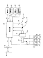
図1は本発明の第1の実施形態を示すシステム構成図であり、図中、21FL,21FRは自動車の前輪、21RL,21RRは自動車の後輪であって、これら前輪21FL,21FR及び後輪21RL,21RRには夫々例えばディスクブレーキで構成されるブレーキアクチュエータ22FL,22FR及び22RL,22RRが装着されている。
【0013】
各ブレーキアクチュエータ22FL〜22RRの夫々は、供給される制動圧に応じた制動力を発生するように構成され、各ブレーキアクチュエータ22FL〜22RRがブレーキペダル23に電子式負圧ブースタ24を介して連結されたマスタシリンダ25に連結されている。
ここで、電子式負圧ブースタ24は、図2に示すように、変圧室1と負圧室2とがダイヤフラム14によって画成され、変圧室1はブレーキ非作動時はエンジン負圧によって定まる負圧状態となって、負圧室2と圧力釣り合い状態にあり、ブレーキ作動時には大気が導入され、負圧室2との差圧が生じて、マスタシリンダ25に倍力された荷重が伝達される。負圧室2は、エンジン始動中は常に所定の負圧に維持されている。
【0014】
そして、ダイヤフラム14の中央部には軸筒17が固定され、この軸筒17内に負圧室2と変圧室1とを連通する連通路11が形成され、この連通路11の右端側開口部に真空弁3が配設され、この真空弁3は運転者によってブレーキペダル23がストロークしたとき或いは電磁弁5が励磁されたときに閉じ、負圧室2と変圧室1との連通を遮断する。
【0015】
また、変圧室1と大気との間には大気弁4が配設され、この大気弁4は、後述する摺動筒体5bに形成された弁体12と協働して動作し、運転者によりブレーキペダル23がストロークしたとき或いは電磁弁5が励磁されたときに開き、変圧室1に大気が導入される。
電磁弁5は、軸筒17の内周部に配設されたソレノイド5aと、このソレノイド5aと対向して摺動自在に配設された摺動筒体5bとで構成され、摺動筒体5bの右端側に前述した真空弁3及び大気弁4を作動させる係合部18が形成されている。
【0016】
この摺動筒体5bは、負圧室2内に配設されたリターンスプリング15によって右方向に付勢されているとともに、内部には、オペレーティングロッド6が配設され、このオペレーティングロッド6の先端がプッシュロッド8を介してマスタシリンダ25に連結されている。
また、オペレーティングロッド6と軸筒17及び真空弁3,大気弁4との間に夫々リターンスプリング13a及び13bが配設されていると共に、オペレーティングロッド6と摺動筒体5bとの間にリターンスプリング16が配設されている。
【0017】
図1に戻って、オペレーティングロッド6には、プレーキペダル23が取付けられていると共に、このブレーキペダル23の踏込みを検出するブレーキスイッチ26が配設されている。
一方、アクセルペダル27には、そのストロークを検出するアクセルストロークセンサ28が配設されている。
【0018】
さらに、マスタシリンダ25の出力側配管にはブレーキ圧を検出するブレーキ圧センサ33が配設されている。
そして、電子式負圧ブースタ25の電磁弁5が制御装置29によって制御される。この制御装置29には、ブレーキスイッチ26、アクセルストロークセンサ28、ブレーキ圧センサ33の各検出信号が入力されると共に、例えば変速機の出力側に設けられた車速センサ30からの自車速Vm、車両前方のフロントグリルに配設されたレーザーレーダ、ミリ波レーダ等で構成される制動対象物検出手段としての車間距離センサ31からの車間距離L及びサスペンションと車体との間に介挿された荷重センサ32からの車体重量Mが入力され、これらに基づいてブレーキ予圧を必要とする要ブレーキ予圧状態であるか否かを判断する判断距離L0を算出し、車間距離Lが判断距離L0以下となったときにブレーキ予圧PPSを設定し、制動圧センサ33で検出した制動圧がブレーキ予圧PPBと一致するように電磁弁5を制御するブレーキ制御処理を行うと共に、車間距離センサ31で検出した車間距離Lに基づいてこの車間距離Lを設定距離に制御する追従走行制御処理を行う。ここで、追従走行制御処理は、運転席近傍に設けられた作動開始スイッチ34がセットされたときに処理を開始し、車間距離Lが設定車間距離範囲L1〜L2内に一致するように制動圧指令値PBCを演算すると共に、エンジン出力を制御するスロットルバルブ35のスロットル開度を変更するスロットル駆動モータ36を駆動制御するスロットル開度指令値θを演算する。ここで、荷重センサ32としては、ロードセンシングバルブを用いて、フロント及びリヤの輪荷重を計測して車体重量mを求めるように構成されている。
【0019】
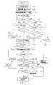
次に、上記第1の実施形態の動作を制御装置29の処理手順を示す図3のフローチャートを伴って説明する。
制御装置29は、図3の制御処理を所定時間(例えば10msec)毎のタイマ割込処理として実行し、先ず、ステップS1で、車速センサ30で検出した自車速Vmを読込み、次いでステップS2に移行して、車間距離センサ31で検出した車間距離Lを読込み、次いでステップS3に移行して、今回の車間距離L(n)1と前回の車間距離L(n-1) とに基づいて相対速度に相当する車間距離の微分値(車間距離変化量)dL/dtを算出してからステップS4に移行する。
【0020】
このステップS4では、自車速Vm、車間距離微分値dL/dt及び今回の車間距離L(n) をもとに下記(1)式の演算を行って目標減速度GB を算出する。
GB ={Vm2 −(Vm−dL/dt)2 }/2L(n) …………(1)
次いで、ステップS5に移行して、後述する要ブレーキ状態となった時点からの経過時間を計測する経過時間カウンタのカウント値Tpが“0”であるか否かを判定し、Tp=0であるときには、要ブレーキ予圧状態となっていないものと判断してステップS6に移行し、ステップS4で算出した目標減速度GB が予め設定した設定値GBSを越えているか否かを判定し、GB ≦GBSであるときには、ブレーキ予圧の必要がないものと判断しステップS7に移行してブレーキ予圧PSTを“0”に設定してから後述するステップS16以降の追従制御処理に移行し、GB >GBSであるときには、ブレーキ予圧を必要とする要ブレーキ予圧状態であると判断してステップS8に移行する。
【0021】
このステップS8では、アクセルストロークセンサ28で検出したアクセルストローク値Laを読込んで、アクセルペダル27が踏込まれているか否かを判定し、アクセルペダル27が踏込まれているときには、ブレーキ予圧の必要がないものと判断して前記ステップS7に移行し、アクセルペダル27が解放されているときには、ステップS9に移行する。
【0022】
このステップS9では、ブレーキ予圧開始車速V0を読込み、このブレーキ予圧開始車速V0及び車体重量Mをもとに図4に示すブレーキ予圧算出マップを参照してブレーキ予圧PPBを算出し、これを所定記憶領域に更新記憶してからステップS10に移行して、要ブレーキ予圧状態となった時点からの経過時間を計測するソフトウェアカウンタでなる経過時間カウンタのカウント値Tpを“1”だけインクリメントしてから後述するステップS16以降の追従制御処理に移行する。
【0023】
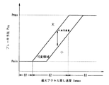
ここで、ブレーキ予圧算出マップは、図5に示すように、要ブレーキ予圧状態となったときの自車速V0と自動制御時のブレーキ圧PPBの設定値との関係を表し、要ブレーキ予圧状態となったときの自車速V0が高い程、ブレーキ圧は同じでも運転者が感じる減速度は小さく、低速時にはこの感じ方は大きいことを考慮して、特性曲線を低速部A1で一定の最小値Pminを持ち、高速部A3で一定の最大値Pmaxを持ち、中速部a2では最小値Pminと最大値Pmaxとの直線的補間値をとるように設定されている。さらに、図4の特性曲線に車体重量Mに対応して設定圧の補正を行い、車体重量Mが大きい程ブレーキ圧の影響も少ないことから、設定圧を高めに補正する。
【0024】
一方、前記ステップS5の判定結果が、カウンタのカウント値TpがTp>0であるときには、ステップS11に移行して、ブレーキスイッチ23のスイッチ信号を読込み、ブレーキペダル23が踏込まれているか否かを判定し、ブレーキペダル23が踏込まれているときには、ステップS12に移行して経過時間カウンタのカウント値Tpを“0”にクリアしてから前記ステップS7に移行し、ブレーキペダル23が解放されているときにはステップS13に移行する。
【0025】
このステップS13では、アクセルストロークセンサ28で検出したアクセルストローク値Laを読込み、これに基づいてアクセルペダル27が踏込まれているか否かを判定し、アクセルペダル27が踏込まれているときには、ブレーキ予圧の必要性がない要ブレーキ予圧状態ではないものと判断して前記ステップS12に移行し、アクセルペダル27が解放されているときには要ブレーキ予圧状態であると判断して、ステップS14に移行する。
【0026】
このステップS14では、経過時間カウンタのカウント値TP が緊急ブレーキ時にアクセルペダル27を解放してからブレーキペダル21が踏込まれるまでの最大経過時間でなる設定値TS に達したか否かを判定し、TP <TS であるときにはステップS15に移行して、前回設定されたブレーキ予圧PPB(n-1) をそのまま今回のブレーキ予圧PPBとして設定してから前記ステップS10に移行し、TP ≧TS であるときには緊急ブレーキの必要性が低下したものと判断して前記ステップS12に移行する。
【0027】
ステップS16では、追従制御開始スイッチ34がオン状態にセットされているか否かを判定し、これがオフ状態であるときには、追従制御を行わないものと判断してステップS17に移行して、追従制御用ブレーキ圧PBCを“0”に設定し、次いでステップS18に移行して、エンジン出力の制御を行わないスロットル開度指令値θを“0”に設定してからステップS19に移行して、ブレーキ制御処理で設定したブレーキ予圧PPBと追従制御処理で設定したブレーキ圧PBCとの何れか高い方を選択するセレクトハイ処理を行い、選択したブレーキ圧PSLに制動圧センサ33で検出したブレーキ圧PW が一致するように電磁弁5に対する通電量を制御してからタイマ割込み処理を終了して所定のメインプログラムに復帰する。
【0028】
また、ステップS16の判定結果が、追従制御開始スイッチ34がオン状態にセットされているときには、ステップS20に移行して、アクセルストロークセンサ28で検出したアクセルストローク値Laを読込んで、アクセルペダル27が踏込まれているか否かを判定し、アクセルペダル27が踏込まれているときにはステップS21に移行して、追従制御処理を終了すると共に、追従制御開始スイッチ34をオフ状態に復帰させてから前記ステップS19に移行し、アクセルペダル27が解放されているときには、ステップS22に移行する。
【0029】
このステップS22では、車間距離センサ31で検出した車間距離Lが第1の設定車間距離L1未満であるか、第1の設定車間距離L1以上でこの第1の設定車間距離L1より長い第2の設定車間距離L2以下であるか、第2の設定車間距離L2を越えているかを判定し、L1≦L≦L2であるときには、適正車間距離を維持しているものと判断して前記ステップS19に移行し、L<L1であるときには車間距離が短すぎるものと判断してステップS23に移行して、現在のブレーキ圧PBCに所定値ΔPBCを加算した値を新たなブレーキ圧PBCとして設定してから前記ステップS20に移行し、L>L2であるときには車間距離Lが適正範囲を越えて広すぎると判断してステップS24に移行する。
【0030】
このステップS24では、前記ステップS19と同様にブレーキ圧PBCを“0”に設定し、次いでステップS25に移行して、前述したブレーキ制御処理におけるブレーキ予圧PPBが“0”であるか否かを判定し、PPB>0であるときにはブレーキ予圧発生状態であると判断してそのまま前記ステップS21に移行し、PPB=0であるときには、ブレーキ予圧が解除されているものと判断してステップS26に移行する。
【0031】
このステップS26では、現在のスロットル開度指令値θに予め設定された所定値Δθを加算した値を新たなスロットル開度指令値θとして算出し、これに対応する駆動指令をスロットル駆動モータ36に出力してから前記ステップS21に移行する。
この図3の制御処理において、ステップS1〜ステップS17の処理がブレーキ制御手段に対応し、このうちステップS1〜S8の処理が要ブレーキ予圧状態検出手段に対応し、ステップS8の処理がブレーキ予圧解除手段に対応しており、またステップS16〜S26の処理が追従走行制御手段に対応し、このうちステップS25の処理が加速制御禁止手段に対応している。
【0032】
この実施形態によると、追従制御開始スイッチ34がオフ状態であって、追従制御処理が中止されている状態では、図3におけるステップS1〜S17のブレーキ制御処理のみが実行されることになり、このとき経過時間カウンタのカウント値TP が“0”にクリアされているものとすると、先行車がいない場合、先行車がいても十分な車間距離となっている場合及び自車両と先行車とが所定車間距離を保って等速で走行している場合には、ステップS4で算出される目標減速度GB が略零又はこれに近い値となることにより、ステップS6で要ブレーキ予圧状態ではないものと判断されて、ステップS7に移行してブレーキ予圧PPBが“0”に設定され、追従制御開始スイッチ34がオフ状態であるので、ステップS19に移行して、追従制御用ブレーキ圧PBCも“0”に設定され、スロットル開度指令値θも“0”に設定されるので、スロットルバルブ35が運転者のアクセルペダル27の踏込量に応じたスロットル開度となるように制御されて、運転者の所望する車速で走行する。
【0033】
この運転者の所望とする車速で走行している状態で、先行車に接近して、車間距離Lが短くなり、これに応じてステップS4で算出される目標減速度GB が増加して設定値GBSを越える状態となると、ステップS6からステップS8に移行する。このとき、アクセルペダル27を踏込んでいる場合には、運転者が現在のスロットル開度を維持する意志があり、要ブレーキ予圧状態ではないものと判断してステップS7に移行することにより、運転者の意志による走行状態を継続する。
【0034】
しかしながら、目標減速度GB が設定値GBSを越えているときに、運転者がアクセルペダル27を離した場合には、ブレーキ操作を行う可能性が高く、要ブレーキ予圧状態であると判断して、ステップS9に移行し、そのときの自車速V0に応じたブレーキ予圧PPBが算出され、これが所定記憶領域に更新記憶されると共に、ステップS10に移行して経過時間カウンタのカウント値TP が“1”だけカウントアップされる。この状態では、まだ追従制御処理が作動されていないので、追従制御用ブレーキ圧PBCは“0”を維持するので、ステップS21でブレーキ予圧PPBが選択され、これに応じた通電電流が電磁弁5に供給される。このため、負圧ブースタ24の真空弁3が閉じ逆に大気弁4が開くことにより、負圧ブースタ24の変圧室1に大気圧が導入されて、軸筒17が左方に移動してプッシュロッド8を左動させ、マスタシリンダ25から運転者のブレーキ操作に先立ってブレーキ予圧PPBに応じたブレーキ圧が発生されて制動状態となる。
【0035】
このとき、ブレーキ予圧PPBは、自車速Vが低い程小さい値となり、かつ車体重量mが大きい程大きな値となるので、低車速域で乗員数や積載物が少なくて車体重量mが小さい場合にはブレーキ予圧PPBも小さい値となるため、ブレーキ予圧PPBに応じたブレーキ圧による制動状態となっても、運転者に違和感を与えることがなく、運転者のブレーキ操作を見越したプレビューブレーキ制御を行うことができる。
【0036】
一方、要ブレーキ予圧状態となってから先行車が加速したり停止していた先行車が発進することにより、運転者がアクセルペダル27の解放後直ちにブレーキペダル23を踏込まないときには、経過時間カウンタのカウント値TP が設定値TS に達するまでの間はステップS14からステップS15に移行することにより、最初に設定されブレーキ予圧PPBを維持するが、経過時間カウンタのカウント値TP が設定に達すると、ステップS14からステップS12に移行して、経過時間カウンタのカウント値TP を"0"にクリアしてからステップS7に移行して、ブレーキ予圧PPBが"0"に設定される。これに応じて電磁弁5が非通電状態に制御され、このためマスタシリンダ25で発生されるブレーキ圧PW も"0"となりプレビューブレーキ制御が終了される。
【0038】
一方、図5(a)に示すように、時点t1で目標減速度GB が設定値GBSを越えて、ブレーキ予圧PPBが発生されるプレビューブレーキ制御状態となり、その後アクセルペダル27及びブレーキペダル23を踏込むことなく、経過時間カウンタのカウント値TP が設定値TS に達する以前の時点t2で追従制御開始スイッチ34をオン状態として、図5(b)に示すように、図3におけるステップS16移行の追従制御処理を開始すると、図3におけるステップS16からステップS20に移行し、アクセルペダル27が解放されているので、ステップS22に移行する。
【0039】
このとき、隣接レーンが開いており、先行車を追い越すために自車両を車線変更するか又は、先行車が車線変更して、車間距離センサ31で検出する車間距離Lが急激に第2の設定車間距離L2を越えて長くなると、ステップS4で算出される目標減速度GB が小さい値となるが、図3の処理でステップS1〜ステップS15のブレーキ制御処理では、車間距離センサ31の車間距離検出精度に起因する車間距離の変動によって不用意にブレーキ予圧が解除されることを防止するために、目標減速度GB が小さくなることをブレーキ予圧解除条件としていないので、ブレーキ予圧PPBの発生状態が継続される。一方、ステップS16以降の追従走行制御処理では、車間距離Lが第2の設定車間距離L2を越えているので、ステップS22からステップS24に移行し、追従制御用ブレーキ圧PBCが“0”に設定され、次いでステップS25に移行して、ブレーキ予圧PPBが“0”より大きいので、そのままステップS19に移行することにより、ステップS26での加速制御が禁止され、ステップS19でブレーキ予圧PPBが選択されて、プレビューブレーキ制御状態が継続される。
【0040】
この状態で、時点t3で経過時間タイマのカウント値TP が設定値TS に達すると、ステップS14からステップS12に移行して、カウント値TP が“0”にクリアされると共に、ステップS7に移行して、ブレーキ予圧PPBが“0”にセットされて、プレビューブレーキ制御が解除される。このため、ステップS16以降の追従制御処理では、ステップS23からステップS24に移行して、スロットル開度指令値θを所定値Δθだけ増加させ、これに応じてスロットル駆動モータ36を駆動制御することにより、スロットル開度が図5(c)に示すように増大されて自車両が加速状態なる。このとき、ブレーキ予圧PPBは既に解除されているので、ブレーキを引きずることなく加速状態に滑らかに移行することができ、運転者に違和感を与えることを確実に防止することができる。なお、自車両の加速状態は予め運転者が設定した設定車速に一致するまで継続される。
【0041】
因に、従来例では、ブレーキ制御と追従走行制御との干渉を考慮していないので、図5の時点t2で追従走行制御処理が加速制御状態に移行すると、ブレーキアクチュエータ22FL〜22RRでブレーキ予圧PPBを発生している状態で加速制御が行われることになり、スロットル開度が図5(c)で一点鎖線図示のように必要以上に大きく制御されることになる。このため、時点t3でブレーキ予圧PPBが解除されるオーバートルク状態となって加減速ハンチングを生じて、運転者に違和感を与えるという問題点がある。
【0042】
また、ブレーキ制御処理でブレーキ予圧を発生している状態で、追従制御開始スイッチ34をオン状態として追従制御処理を開始させ、この状態で、先行車を追い越すために、アクセルペダル27を踏込んで加速状態としながら、追い越し車線に車線変更した場合には、ステップS1〜S15のブレーキ制御処理におけるステップS13からステップS12に移行することにより、経過時間カウンタのカウント値TP が“0”にクリアされると共に、ステップS7に移行してブレーキ予圧PPBが“0”に設定されて、直ちにブレーキ予圧状態が解除されることになり、この場合もブレーキを作動させている状態で加速状態となることを確実に防止することができる。このとき、追従走行制御処理では、ステップS20からステップS21に移行することにより、追従制御処理を解除すると共に、追従制御開始スイッチ34をオフ状態に復帰させる。
【0043】
このように、上記実施形態によれば、目標減速度GB が設定値GBSを越える要ブレーキ予圧状態となってから緊急ブレーキ操作に相当する経過時間が経過するまでの間は車体重量M及びブレーキ予圧開始車速V0に基づいて設定されたブレーキ予圧PPBを維持することにより、運転者がブレーキペダル23を踏込んだときに、高応答性をもって確実に制動状態に移行して空走距離を短くすることができるが、アクセルペダル27を解放してからブレーキペダル23を踏込むまでの時間が長い場合には、緊急度合いが小さいものと判断してブレーキ予圧PPBが解除されるので、不必要にプレビューブレーキ制御を継続することがなく、運転者に違和感を与えることを確実に防止することができる。
【0044】
そして、ブレーキ予圧を発生させている状態で、追従走行制御処理で加速制御が必要であると判断されたときに、ブレーキ予圧が解除されるまでの間加速制御の開始を禁止して、ブレーキ予圧が解除されてから加速制御を開始するので、エンジン出力が不必要に増大することを防止して、円滑な加速制御を行って運転者に違和感を与えることを確実に防止することができる。
【0045】
また、ブレーキ予圧を発生させている状態で、運転者による加速操作が行われたときには、ブレーキ予圧を直ちに解除すると共に追従走行制御処理も解除して運転者の意志による走行状態を維持することができる。
なお、上記実施形態においては、経過時間カウンタのカウント値TP が設定値TS に達するまでの間最初に設定したブレーキ予圧PPBを維持する場合について説明したが、これに限定されるものではなく、図7に示すように、ブレーキ予圧PPBが設定されてから時間の経過と共にブレーキ予圧を徐々に減圧するようにしてもよく、また図7で一点鎖線図示のように経過時間が所定時間に達するまので間は比較的緩い勾配でブレーキ予圧PPBを減少させ、所定時間を越えると比較的急な勾配でブレーキ予圧PPBを減少させるようにしてもよく、さらには、直線的に減少させる場合に代えて曲線的に減少させるようにしてもよい。
【0046】
また、上記実施形態においては、要ブレーキ予圧状態となったときの自車速に基づいてブレーキ予圧PPBを設定する場合について説明したが、これに限らず、アクセル戻し速度に基づいてブレーキ予圧PPBを設定するようにしてもよく、さらには、路面状態を検出して路面摩擦係数が小さくなるに応じてブレーキ予圧PPBを小さくするようにしてもよい。さらに、ブレーキ予圧PPBを変速機のシフト位置が1速位置であるときに最大値Pmaxに設定し、これよりシフト位置が高速側となるに従ってブレーキ予圧PPBを徐々に低下させるようにしてもよく、この場合には、シフト位置が低速側に行くに従いエンジンブレーキ力が大きくなることから、大きなブレーキ予圧を与えても、運転者が違和感を抱くことがなく、より高い応答性をもってプレビューブレーキ制御を行うことができる。
【0047】
さらに、上記実施形態においては、加速操作の終了をアクセルペダル27のストロークから検出する場合について説明したが、これに限定されるものではなく、スロットル開度が“0”であることを検出するようにしてもよく、さらにはアクセルペダル27にその踏込みを検出するアクセルスイッチを設けるようにしてもよい。
【0048】
同様に、ブレーキ操作についてもブレーキスイッチ26に限らず、ブレーキペダル23のストロークから検出したり、ブレーキ圧センサ33で検出したブレーキ圧がブレーキ予圧以上となったときにブレーキ操作を開始したものとして検出するようにしてもよい。
さらにまた、上記実施形態においては、車体重量Mをパラメータとしてブレーキ予圧を設定する場合について説明したが、これに限定されるものではなく、車体重量Mを所定値に固定してブレーキ予圧を算出するようにしてもよい。
【0049】
なおさらに、上記実施形態においては、車間距離センサ31で先行車を検出している場合について説明したが、これに限定されるものではなく、道路上の落下物等のブレーキ操作を必要とする障害物を検出した場合も上記と同様にプレビューブレーキ制御が行われる。
また、上記実施形態においては、演算によって相対速度を算出する場合について説明したが、これに限定されるものではなく、相対速度を検出することができる車間距離センサを適用した場合は、検出した相対速度をそのまま使用することができる。
【0050】
さらに、上記実施形態においては、負圧ブースタ24に電磁弁5を組込むことにより、ブレーキ予圧PPBに応じたブレーキ圧PW を発生させるようにした場合について説明したが、これに限定されるものではなく、別途油圧ポンプ等の流体圧源を設け、この流体圧源の流体圧を圧力制御弁等で圧力制御してブレーキ予圧PPBを発生させ、これをブレーキアクチュエータに供給するようにしてもよい。
【0051】
さらにまた、上記実施形態においては、マスタシリンダ25を使用してブレーキ圧を発生させる場合について説明したが、これに限定されるものではなく、ブレーキアクチュエータとして電動モータを使用して制動力を発生させる場合には、ブレーキ予圧PPBに基づいて電動モータの駆動電流を制御するようにしてもよい。
【0052】
なおさらに、上記実施形態においては、車間距離Lを第1の車間距離L1及び第2の車間距離L2間に維持するように追従走行制御する場合について説明したが、これに限定されるものではなく、自車速に車間時間を乗算して目標車間距離L* を算出し、この目標車間距離L* に車間距離Lが一致するように駆動力及び制動力を制御するようにしてもよい。
【図面の簡単な説明】
【図1】本発明の第1の実施形態を示すシステム構成図である。
【図2】第1の実施形態に適用し得る電子式負圧ブースタの断面図である。
【図3】第1の実施形態における制御装置の制御処理手順の一例を示すフローチャートである。
【図4】車体重量をパラメータとした自車速とブレーキ予圧との関係を表すブレーキ予圧算出マップを示す特性線図である。
【図5】上記実施形態の動作の説明に供するタイムチャートである。
【図6】ブレーキ予圧の変化を示すタイムチャートである。
【符号の説明】
21FL〜21RR 車輪
22FL〜22RR ブレーキアクチュエータ
23 ブレーキペダル
24 電子式負圧ブースタ
25 マスタシリンダ
26 ブレーキスイッチ
27 アクセルペダル
28 アクセルストロークセンサ
29 制御装置
30 車速センサ
31 車間距離センサ
32 荷重センサ
33 ブレーキ圧センサ
35 スロットルバルブ
36 スロットル駆動モータ[0001]
BACKGROUND OF THE INVENTION
According to the present invention, an inter-vehicle distance between a brake control unit that generates a brake pre-load when a brake pre-load is required and requires a brake pre-load when a forward braking object is detected, and the following target vehicle The present invention relates to a travel control device including follow-up travel control means for performing follow-up travel control so as to maintain a distance.
[0002]
[Prior art]
Regarding brake control among conventional travel control devices, for example, as in the technique described in Japanese Patent Application Laid-Open No. 7-144588, rear-end collision is performed when the distance between the front obstacle and the host vehicle is less than a predetermined safety distance. A vehicle rear-end collision prevention device that performs automatic brake control to prevent it from happening, and a driver's foot heel with accelerator information on the heel stop, such as a technique described in Japanese Patent Application Laid-Open No. 6-24302, There is known an automatic preliminary braking system that performs detection by a saddle detection means that detects and performs preliminary braking before a brake operation. For example, Japanese Patent Application Laid-Open No. 10-114237 discloses the following traveling control. During follow-up control, when the driver depresses the accelerator pedal to overtake the vehicle and makes an acceleration lane change, the follow-up control is canceled and the vehicle follows the driver's will. Follow-up cruise control apparatus is known.
[0003]
[Problems to be solved by the invention]
However, if the travel control device has both the brake control function and the follow-up travel control function, after the driver suddenly approaches the braking object and the brake control function is activated, the driver performs the follow-up travel control function. When a start operation is performed to activate the brake, it should be as close as possible to the braking object as long as the brake control function is activated. A case where the demand, that is, the acceleration control that increases the engine output is selected can be considered. In this case, the engine output is increased relative to the brake control by the brake control function. However, the brake control is performed, and the engine output is instructed by the amount corresponding to the braking force acting on the wheels. As a result, when the throttle valve is opened more than necessary, and when the brake control of the brake control function is finished thereafter, there is an unsolved problem that overtorque is generated and acceleration / deceleration hunting occurs, which gives the driver a sense of incongruity.
[0004]
Here, as a factor that causes a contradictory state between braking by the brake control function and driving by the follow-up traveling control function, for example, in the brake control function, a brake preload is generated in order to shorten the idling distance during braking. As a brake preload release condition in this case, the deceleration is set to the set value to prevent the brake preload state from being unnecessarily released due to fluctuations in the inter-vehicle distance detection value caused by the accuracy of the inter-vehicle distance sensor. It is conceivable that the brake preload is released when the elapsed time after entering the brake preload state exceeds the set time without setting the release condition as below, but the deceleration is below the set value in this way. If you set the brake preload release condition when the elapsed time after entering the brake preload state is longer than the set time, When the preceding vehicle is in an accelerated state before reaching the set elapsed time, or the preceding vehicle changes lanes to the adjacent lane, or the host vehicle changes lanes and does not capture the preceding vehicle that is close by the inter-vehicle distance sensor Then, the follow-up running control function generates an acceleration request due to an increase in the inter-vehicle distance. Also, when different external recognition sensors are used for the brake control function and the follow-up travel control function, the brake control function sensor captures the preceding vehicle and generates brake preload, but the follow-up travel control function sensor There is a case where an acceleration request for accelerating to a set vehicle speed is generated in a state where the preceding vehicle is lost. Furthermore, in the brake control, a braking target vehicle traveling at a low speed in front of the vehicle is detected to determine that the brake preload state is required. However, the driver is overtaking the braking target vehicle because the adjacent traveling lane is open. If the brake preload state is not detected by the brake control function in the middle of the lane change by changing the lane while depressing the accelerator pedal and accelerating, To be continued.
[0005]
Therefore, the present invention has been made paying attention to the above-mentioned unsolved problems of the conventional example, and when a demand for acceleration is generated by the follow-up traveling control means in a state where the brake preload is generated, the acceleration operation is performed in the state where the brake preload is generated. An object of the present invention is to provide a travel control device that avoids being performed and does not give the driver a sense of incongruity.
[0006]
[Means for Solving the Problems]
In order to achieve the above object, a travel control device according to
[0007]
In the invention according to
[0008]
According to a second aspect of the present invention, the travel control apparatus includes a braking object detection unit that detects a relative distance to the braking object in front of the vehicle, and is based on the relative distance to the braking object detected by the braking object detection unit. Judgment is made whether the brake preload is required and the brake preload is required. Case In , The mileage can be shortened with high responsiveness when the driver depresses the brake pedal Follow-up running control by controlling the driving force and / or braking force so that the inter-vehicle distance between the brake control means for generating the brake preload and the follow-up running target vehicle ahead of the vehicle is maintained at the target inter-vehicle distance according to the control start operation. In the travel control device comprising the following travel control means, When the brake control means is in a brake preload state where the brake preload is generated and the follow-up running control means enters an acceleration control start state, the start of the acceleration control is prohibited until the brake preload state is released. Acceleration control prohibition means, In the brake preload state where the brake preload is generated by the brake control means ,luck Brake preload release means for releasing the brake preload state of the brake control means when a driver's acceleration operation is performed is provided.
[0009]
In the invention according to
[0010]
【The invention's effect】
According to the first aspect of the present invention, the brake control means Short mileage with high responsiveness when the driver depresses the brake pedal With brake preload generated When the follow-up control means determines that acceleration control is necessary, the acceleration control is prohibited until the brake preload is released, and the acceleration control is started after the brake preload is released. , Prevent the engine output from increasing unnecessarily, and perform smooth acceleration control It is possible to reliably prevent the driver from feeling uncomfortable.
[0011]
According to the invention of
[0012]
DETAILED DESCRIPTION OF THE INVENTION
Hereinafter, embodiments of the present invention will be described with reference to the drawings.
FIG. 1 is a system configuration diagram showing a first embodiment of the present invention, in which 21FL and 21FR are front wheels of an automobile, 21RL and 21RR are rear wheels of the automobile, and these front wheels 21FL and 21FR and rear wheels are shown. Brake actuators 22FL, 22FR and 22RL, 22RR configured by, for example, disc brakes are mounted on 21RL and 21RR, respectively.
[0013]
Each of the brake actuators 22FL to 22RR is configured to generate a braking force corresponding to the supplied braking pressure, and each of the brake actuators 22FL to 22RR is connected to the
Here, in the electronic
[0014]
A
[0015]
Also, an
The
[0016]
The sliding
Return springs 13a and 13b are disposed between the operating
[0017]
Returning to FIG. 1, the operating
On the other hand, the
[0018]
Further, a
The
[0019]
Next, the operation of the first embodiment will be described with reference to the flowchart of FIG.
The
[0020]
In this step S4, the target deceleration G is calculated by calculating the following equation (1) based on the own vehicle speed Vm, the inter-vehicle distance differential value dL / dt and the current inter-vehicle distance L (n). B Is calculated.
G B = {Vm 2 − (Vm−dL / dt) 2 } / 2L (n) (1)
Next, the process proceeds to step S5, where it is determined whether or not the count value Tp of the elapsed time counter that measures the elapsed time from the time when the brake required state described later is reached is “0”, and Tp = 0. In some cases, it is determined that the brake preload required state has not been reached, the process proceeds to step S6, and the target deceleration G calculated in step S4 is obtained. B Is a preset set value G BS J B ≦ G BS When it is, it is determined that the brake preload is not necessary, and the routine proceeds to step S7 where the brake preload P ST Is set to “0” and then the process proceeds to a follow-up control process after step S16, which will be described later. B > G BS If it is, it is determined that the brake preload state that requires brake preload is required, and the process proceeds to step S8.
[0021]
In step S8, the accelerator stroke value La detected by the
[0022]
In this step S9, the brake preload start vehicle speed V0 is read, and the brake preload P is calculated with reference to the brake preload calculation map shown in FIG. 4 based on the brake preload start vehicle speed V0 and the vehicle body weight M. PB Is calculated and stored in a predetermined storage area, and then the process proceeds to step S10, where the count value Tp of the elapsed time counter, which is a software counter that measures the elapsed time from the time when the brake preload state is required, is set to “ After incrementing by 1 ″, the process proceeds to a follow-up control process after step S16 described later.
[0023]
Here, the brake preload calculation map, as shown in FIG. 5, shows the own vehicle speed V0 when the required brake preload state is reached and the brake pressure P during automatic control. PB Considering that the higher the vehicle speed V0 when the brake preload is required, the smaller the deceleration felt by the driver, even at the same brake pressure, and this feeling is greater at low speeds. Thus, the characteristic curve has a constant minimum value Pmin at the low speed part A1, has a constant maximum value Pmax at the high speed part A3, and takes a linear interpolation value between the minimum value Pmin and the maximum value Pmax at the medium speed part a2. Is set to Further, the set pressure is corrected corresponding to the vehicle body weight M in the characteristic curve of FIG. 4, and the influence of the brake pressure is less as the vehicle body weight M is larger, so the set pressure is corrected to be higher.
[0024]
On the other hand, when the determination result of step S5 is that the count value Tp of the counter is Tp> 0, the process proceeds to step S11, where the switch signal of the
[0025]
In this step S13, the accelerator stroke value La detected by the
[0026]
In this step S14, the count value T of the elapsed time counter P Is the set value T that is the maximum elapsed time from when the
[0027]
In step S16, it is determined whether or not the follow-up control start
[0028]
If the determination result in step S16 is that the follow-up control start
[0029]
In this step S22, the second inter-vehicle distance L detected by the
[0030]
In step S24, the brake pressure P is the same as in step S19. BC Is set to "0", and then the process proceeds to step S25, where the brake preload P in the brake control process described above is set. PB Whether or not is "0" and P PB When it is> 0, it is determined that the brake preload is generated, and the process proceeds to step S21 as it is. PB When = 0, it is determined that the brake preload is released, and the process proceeds to step S26.
[0031]
In this step S26, a value obtained by adding a predetermined value Δθ set in advance to the current throttle opening command value θ is calculated as a new throttle opening command value θ, and a drive command corresponding to this is sent to the
In the control process of FIG. 3, the processes of steps S1 to S17 correspond to the brake control means, of which the processes of steps S1 to S8 correspond to the brake preload state detecting means, and the process of step S8 is the brake preload release. In addition, the processing in steps S16 to S26 corresponds to the following travel control means, and among these, the processing in step S25 corresponds to the acceleration control prohibiting means.
[0032]
According to this embodiment, when the follow-up control start
[0033]
While traveling at the vehicle speed desired by the driver, the vehicle approaches the preceding vehicle and the inter-vehicle distance L is shortened, and the target deceleration G calculated in step S4 accordingly. B Increases to set value G BS If the state exceeds, the process proceeds from step S6 to step S8. At this time, if the
[0034]
However, the target deceleration G B Is the set value G BS If the driver releases the
[0035]
At this time, brake preload P PB Is smaller as the vehicle speed V is lower and increases as the vehicle body weight m is larger. Therefore, when the vehicle body weight m is small because the number of passengers and loads is small in the low vehicle speed range, the brake preload P PB Is also a small value, so brake preload P PB Even when the braking state is in accordance with the braking pressure according to the above, preview brake control can be performed in anticipation of the driver's brake operation without causing the driver to feel uncomfortable.
[0036]
On the other hand, when the driver does not depress the
[0038]
On the other hand, as shown in FIG. 5A, the target deceleration G at time t1. B Is the set value G BS Brake preload P PB The preview brake control state is generated, and then the count value T of the elapsed time counter is depressed without depressing the
[0039]
At this time, the adjacent lane is open, and the own vehicle is changed to lane in order to pass the preceding vehicle, or the preceding vehicle is changed to the lane, and the inter-vehicle distance L detected by the
[0040]
In this state, the count value T of the elapsed time timer at time t3. P Is the set value T S , The process proceeds from step S14 to step S12, and the count value T P Is cleared to "0" and the process proceeds to step S7, where the brake preload P PB Is set to “0” and the preview brake control is released. For this reason, in the follow-up control process after step S16, the routine proceeds from step S23 to step S24, where the throttle opening command value θ is increased by a predetermined value Δθ, and the
[0041]
Incidentally, in the conventional example, since interference between the brake control and the follow-up running control is not considered, when the follow-up running control process shifts to the acceleration control state at time t2 in FIG. 5, the brake preload P is applied by the brake actuators 22FL to 22RR. PB Thus, the acceleration control is performed in a state where the engine is generated, and the throttle opening is controlled to be larger than necessary as shown by the one-dot chain line in FIG. 5C. Therefore, the brake preload P at time t3 PB There is a problem that acceleration / deceleration hunting occurs in an overtorque state in which the is released, giving the driver a sense of incongruity.
[0042]
Further, in the state where the brake preload is generated in the brake control process, the tracking control start
[0043]
Thus, the above embodiment In According to the target deceleration G B Is the set value G BS The brake preload P set based on the vehicle weight M and the brake preload start vehicle speed V0 until the elapsed time corresponding to the emergency brake operation elapses after the brake preload state exceeding PB By maintaining this, when the driver steps on the
[0044]
When it is determined that acceleration control is required in the follow-up running control process while the brake preload is being generated, the start of the acceleration control is prohibited until the brake preload is released. Since the acceleration control is started after the engine is released, it is possible to prevent the engine output from increasing unnecessarily and to surely prevent the driver from feeling uncomfortable by performing the smooth acceleration control.
[0045]
In addition, when an acceleration operation is performed by the driver while the brake preload is generated, the brake preload is immediately released and the following traveling control process is also canceled to maintain the driving state according to the driver's will. it can.
In the above embodiment, the count value T of the elapsed time counter P Is the set value T S The brake preload P that was initially set until PB However, the present invention is not limited to this, and as shown in FIG. PB The brake preload may be gradually reduced as time elapses after the time is set, and the brake preload has a relatively gentle slope until the elapsed time reaches a predetermined time as shown by the dashed line in FIG. P PB When the specified time is exceeded, the brake preload P increases with a relatively steep slope. PB May be reduced, and may be reduced in a curved line instead of linearly.
[0046]
In the above embodiment, the brake preload P is based on the own vehicle speed when the brake preload is required. PB However, the present invention is not limited to this, and the brake preload P is determined based on the accelerator return speed. PB Further, the brake preload P may be set as the road surface condition is detected and the road surface friction coefficient decreases. PB May be made smaller. In addition, brake preload P PB Is set to the maximum value Pmax when the shift position of the transmission is at the first speed position, and the brake preload P is increased as the shift position becomes higher. PB In this case, the engine braking force increases as the shift position goes to the low speed side, so that even if a large brake preload is applied, the driver does not feel uncomfortable. Therefore, the preview brake control can be performed with higher responsiveness.
[0047]
Furthermore, in the above-described embodiment, the case where the end of the acceleration operation is detected from the stroke of the
[0048]
Similarly, the brake operation is not limited to the
Furthermore, in the above embodiment, the case where the brake preload is set using the vehicle body weight M as a parameter has been described. However, the present invention is not limited to this, and the vehicle body weight M is fixed to a predetermined value to calculate the brake preload. You may do it.
[0049]
Furthermore, in the above-described embodiment, the case where the preceding vehicle is detected by the
In the above embodiment, the case where the relative speed is calculated by calculation has been described. However, the present invention is not limited to this, and the detected relative speed is applied when an inter-vehicle distance sensor capable of detecting the relative speed is applied. The speed can be used as it is.
[0050]
Further, in the above embodiment, the brake preload P is obtained by incorporating the
[0051]
Furthermore, in the above embodiment, the case where the brake pressure is generated using the
[0052]
Furthermore, in the above-described embodiment, the description has been given of the case where the following traveling control is performed so that the inter-vehicle distance L is maintained between the first inter-vehicle distance L1 and the second inter-vehicle distance L2. However, the present invention is not limited to this. , Multiply the vehicle speed by the inter-vehicle time, and the target inter-vehicle distance L * And the target inter-vehicle distance L * The driving force and the braking force may be controlled so that the inter-vehicle distance L coincides with the vehicle.
[Brief description of the drawings]
FIG. 1 is a system configuration diagram showing a first embodiment of the present invention.
FIG. 2 is a cross-sectional view of an electronic negative pressure booster applicable to the first embodiment.
FIG. 3 is a flowchart illustrating an example of a control processing procedure of the control device according to the first embodiment.
FIG. 4 is a characteristic diagram showing a brake preload calculation map representing the relationship between the vehicle speed and the brake preload with the vehicle body weight as a parameter.
FIG. 5 is a time chart for explaining the operation of the embodiment.
FIG. 6 is a time chart showing changes in brake preload.
[Explanation of symbols]
21FL-21RR wheel
22FL-22RR Brake actuator
23 Brake pedal
24 Electronic negative pressure booster
25 Master cylinder
26 Brake switch
27 Accelerator pedal
28 Accelerator stroke sensor
29 Controller
30 Vehicle speed sensor
31 Inter-vehicle distance sensor
32 Load sensor
33 Brake pressure sensor
35 Throttle valve
36 Throttle drive motor
Claims (2)
Priority Applications (4)
| Application Number | Priority Date | Filing Date | Title |
|---|---|---|---|
| JP2000043398A JP3666342B2 (en) | 2000-02-21 | 2000-02-21 | Travel control device |
| US09/789,012 US6405121B2 (en) | 2000-02-21 | 2001-02-21 | Control of incompatible torque requests in vehicle speed control |
| EP01301513A EP1127728B1 (en) | 2000-02-21 | 2001-02-21 | Control of incompatible torque requests in vehicle speed control |
| DE60127480T DE60127480T2 (en) | 2000-02-21 | 2001-02-21 | Method for managing incompatible torque requirements in a cruise control system |
Applications Claiming Priority (1)
| Application Number | Priority Date | Filing Date | Title |
|---|---|---|---|
| JP2000043398A JP3666342B2 (en) | 2000-02-21 | 2000-02-21 | Travel control device |
Publications (2)
| Publication Number | Publication Date |
|---|---|
| JP2001233089A JP2001233089A (en) | 2001-08-28 |
| JP3666342B2 true JP3666342B2 (en) | 2005-06-29 |
Family
ID=18566322
Family Applications (1)
| Application Number | Title | Priority Date | Filing Date |
|---|---|---|---|
| JP2000043398A Expired - Lifetime JP3666342B2 (en) | 2000-02-21 | 2000-02-21 | Travel control device |
Country Status (4)
| Country | Link |
|---|---|
| US (1) | US6405121B2 (en) |
| EP (1) | EP1127728B1 (en) |
| JP (1) | JP3666342B2 (en) |
| DE (1) | DE60127480T2 (en) |
Families Citing this family (30)
| Publication number | Priority date | Publication date | Assignee | Title |
|---|---|---|---|---|
| JP3552628B2 (en) * | 2000-02-21 | 2004-08-11 | 日産自動車株式会社 | Travel control device |
| JP3473563B2 (en) | 2000-08-17 | 2003-12-08 | 日産自動車株式会社 | Braking control device |
| US6304808B1 (en) * | 2000-09-09 | 2001-10-16 | Kelsey-Hayes Company | Enhanced active brake control system functionality through system integration with adaptive cruise control |
| DE10118707A1 (en) * | 2001-04-12 | 2002-10-17 | Bosch Gmbh Robert | Collision avoidance system for vehicles involves preparatory measure to accelerate conversion of command for later output to decelerate vehicle without itself having significant decelerating effect |
| DE10118708A1 (en) * | 2001-04-12 | 2002-10-17 | Bosch Gmbh Robert | Regulating motor vehicle speed involves outputting signal for biasing brake system if acceleration demand signal falls below threshold above value at which brake system is activated |
| US20020175012A1 (en) * | 2001-05-23 | 2002-11-28 | Sun Wen Jun | Control system of vehicle cruise device |
| US6655749B2 (en) | 2001-11-08 | 2003-12-02 | Ford Global Technologies, Llc | Accelerator actuated emergency braking system |
| US6523912B1 (en) * | 2001-11-08 | 2003-02-25 | Ford Global Technologies, Inc. | Autonomous emergency braking system |
| JP4147976B2 (en) * | 2002-09-13 | 2008-09-10 | 日産自動車株式会社 | Combined brake coordination controller |
| US6998727B2 (en) * | 2003-03-10 | 2006-02-14 | The United States Of America As Represented By The Administrator Of The Environmental Protection Agency | Methods of operating a parallel hybrid vehicle having an internal combustion engine and a secondary power source |
| US20050049771A1 (en) * | 2003-08-27 | 2005-03-03 | Ming Kuang | System and method for improving driveability and performance of a hybrid vehicle |
| US6876098B1 (en) | 2003-09-25 | 2005-04-05 | The United States Of America As Represented By The Administrator Of The Environmental Protection Agency | Methods of operating a series hybrid vehicle |
| JP2005297945A (en) * | 2004-03-18 | 2005-10-27 | Advics:Kk | Apparatus and method for controlling vehicular brake |
| JP4576922B2 (en) * | 2004-08-06 | 2010-11-10 | 日産自動車株式会社 | Vehicle travel control device |
| EP1675084A1 (en) * | 2004-12-24 | 2006-06-28 | Carmelo Pagano | Global control system for the protection of territory |
| JP2006259895A (en) * | 2005-03-15 | 2006-09-28 | Omron Corp | Start control device for movable body |
| US7319927B1 (en) * | 2005-05-12 | 2008-01-15 | Kelsey-Hayes Company | Constant speed control system |
| US20090132142A1 (en) * | 2005-10-07 | 2009-05-21 | Eaton Corporation | Adaptive cruise control for heavy-duty vehicles |
| US7957874B2 (en) * | 2007-03-19 | 2011-06-07 | GM Global Technology Operations LLC | Override of automatic braking in a collision mitigation and/or avoidance system |
| CN101987579A (en) * | 2009-08-07 | 2011-03-23 | 鸿富锦精密工业(深圳)有限公司 | Equipment for collecting kinetic energy of vehicle |
| IT1396698B1 (en) * | 2009-11-11 | 2012-12-14 | Nilfisk Advance Spa | PERFECT VEHICLE FOR THE TREATMENT AND CLEANING OF FLOORS AND SOILS |
| US8718896B2 (en) * | 2012-07-02 | 2014-05-06 | Ford Global Technologies, Llc | Hybrid vehicle and associated output torque control method |
| US9481351B2 (en) | 2012-07-02 | 2016-11-01 | Ford Global Technologies, Llc | Hybrid vehicle and associated engine start and stop control method |
| GB2508461B (en) * | 2012-08-16 | 2014-12-17 | Jaguar Land Rover Ltd | Vehicle speed control system and method employing torque balancing |
| JP6082265B2 (en) * | 2013-02-14 | 2017-02-15 | 富士重工業株式会社 | Driving support control device |
| US9873412B2 (en) * | 2013-04-23 | 2018-01-23 | Toyota Jidosha Kabushiki Kaisha | Vehicle speed control apparatus |
| KR20150103357A (en) * | 2013-10-15 | 2015-09-10 | 재규어 랜드 로버 리미티드 | Vehicle speed control system and method employing torque balancing |
| JP2018118667A (en) * | 2017-01-26 | 2018-08-02 | ヤマハ発動機株式会社 | Outboard engine |
| WO2019145280A1 (en) * | 2018-01-23 | 2019-08-01 | Robert Bosch Gmbh | Braking system and method for providing an extra torque from a motor to a brake pedal |
| CN111169472A (en) * | 2018-11-13 | 2020-05-19 | 河南森源重工有限公司 | Vehicle active safety control method and device and vehicle |
Family Cites Families (11)
| Publication number | Priority date | Publication date | Assignee | Title |
|---|---|---|---|---|
| JP2664829B2 (en) | 1991-07-23 | 1997-10-22 | ティン、フシン、ウー | Automatic braking system for automobiles |
| JP3569926B2 (en) * | 1993-03-03 | 2004-09-29 | 株式会社デンソー | Vehicle travel control device |
| JP3064770B2 (en) | 1993-11-25 | 2000-07-12 | トヨタ自動車株式会社 | Vehicle rear-end collision prevention device |
| US5839534A (en) * | 1995-03-01 | 1998-11-24 | Eaton Vorad Technologies, Llc | System and method for intelligent cruise control using standard engine control modes |
| JPH10114237A (en) | 1996-10-09 | 1998-05-06 | Toyota Motor Corp | Follow-up running control device |
| JP3477015B2 (en) * | 1996-12-25 | 2003-12-10 | トヨタ自動車株式会社 | Inter-vehicle distance control device |
| JP3651259B2 (en) * | 1998-05-01 | 2005-05-25 | 日産自動車株式会社 | Preceding vehicle tracking control device |
| JP2000043398A (en) | 1998-07-30 | 2000-02-15 | Toppan Printing Co Ltd | Ink jet recording medium and production thereof |
| JP3675240B2 (en) * | 1999-07-19 | 2005-07-27 | 日産自動車株式会社 | Vehicle tracking control device |
| JP2001055060A (en) * | 1999-08-17 | 2001-02-27 | Toyota Motor Corp | Vehicle speed reducer |
| US6415230B1 (en) | 1999-09-06 | 2002-07-02 | Nissan Motor Co., Ltd. | Method and apparatus for assisting vehicle operator braking action of a vehicle |
-
2000
- 2000-02-21 JP JP2000043398A patent/JP3666342B2/en not_active Expired - Lifetime
-
2001
- 2001-02-21 EP EP01301513A patent/EP1127728B1/en not_active Expired - Lifetime
- 2001-02-21 US US09/789,012 patent/US6405121B2/en not_active Expired - Lifetime
- 2001-02-21 DE DE60127480T patent/DE60127480T2/en not_active Expired - Lifetime
Also Published As
| Publication number | Publication date |
|---|---|
| EP1127728A3 (en) | 2002-05-15 |
| DE60127480T2 (en) | 2008-01-03 |
| DE60127480D1 (en) | 2007-05-10 |
| EP1127728B1 (en) | 2007-03-28 |
| EP1127728A2 (en) | 2001-08-29 |
| US20010049578A1 (en) | 2001-12-06 |
| US6405121B2 (en) | 2002-06-11 |
| JP2001233089A (en) | 2001-08-28 |
Similar Documents
| Publication | Publication Date | Title |
|---|---|---|
| JP3666342B2 (en) | Travel control device | |
| JP5119768B2 (en) | Vehicle braking / driving control device for controlling braking and starting of vehicle | |
| US6769504B2 (en) | Adaptive cruise control system for vehicle | |
| US6134497A (en) | Vehicle running control apparatus and vehicle running control method | |
| USRE41410E1 (en) | Vehicle deceleration control apparatus | |
| JP3473563B2 (en) | Braking control device | |
| US7809488B2 (en) | Headway maintenance system and method | |
| JP4020232B2 (en) | Pre-brake control device | |
| JP3929668B2 (en) | Pre-brake control device | |
| US6502908B1 (en) | Control system for a vehicle | |
| JPH10157585A (en) | Method for performing automatic braking effect | |
| EP2018636A2 (en) | Alarm system and alarm method for vehicle | |
| JP3552628B2 (en) | Travel control device | |
| US6626257B2 (en) | Method and device for automatic speed adjustment in a vehicle | |
| JP2001171497A (en) | Collision preventing device for vehicle | |
| JP3325590B2 (en) | Automatic vehicle braking system | |
| JP3572448B2 (en) | Brake control device for vehicle | |
| JP3651289B2 (en) | Brake control device | |
| JP3543543B2 (en) | Inter-vehicle distance control device | |
| JP3543544B2 (en) | Brake assist device | |
| JP3134559B2 (en) | Vehicle control device | |
| JP3238588B2 (en) | Inter-vehicle distance control device | |
| EP1336526A2 (en) | Automatic running control method, system, and ACC controller for automotive vehicle | |
| JPH11334553A (en) | Run controller for vehicle | |
| JPH11255088A (en) | Brake assist system |
Legal Events
| Date | Code | Title | Description |
|---|---|---|---|
| A131 | Notification of reasons for refusal |
Free format text: JAPANESE INTERMEDIATE CODE: A131 Effective date: 20040323 |
|
| A521 | Written amendment |
Free format text: JAPANESE INTERMEDIATE CODE: A523 Effective date: 20040524 |
|
| TRDD | Decision of grant or rejection written | ||
| A01 | Written decision to grant a patent or to grant a registration (utility model) |
Free format text: JAPANESE INTERMEDIATE CODE: A01 Effective date: 20050315 |
|
| A61 | First payment of annual fees (during grant procedure) |
Free format text: JAPANESE INTERMEDIATE CODE: A61 Effective date: 20050328 |
|
| R150 | Certificate of patent or registration of utility model |
Ref document number: 3666342 Country of ref document: JP Free format text: JAPANESE INTERMEDIATE CODE: R150 Free format text: JAPANESE INTERMEDIATE CODE: R150 |
|
| FPAY | Renewal fee payment (event date is renewal date of database) |
Free format text: PAYMENT UNTIL: 20090415 Year of fee payment: 4 |
|
| FPAY | Renewal fee payment (event date is renewal date of database) |
Free format text: PAYMENT UNTIL: 20090415 Year of fee payment: 4 |
|
| FPAY | Renewal fee payment (event date is renewal date of database) |
Free format text: PAYMENT UNTIL: 20100415 Year of fee payment: 5 |
|
| FPAY | Renewal fee payment (event date is renewal date of database) |
Free format text: PAYMENT UNTIL: 20110415 Year of fee payment: 6 |
|
| FPAY | Renewal fee payment (event date is renewal date of database) |
Free format text: PAYMENT UNTIL: 20120415 Year of fee payment: 7 |
|
| FPAY | Renewal fee payment (event date is renewal date of database) |
Free format text: PAYMENT UNTIL: 20130415 Year of fee payment: 8 |
|
| FPAY | Renewal fee payment (event date is renewal date of database) |
Free format text: PAYMENT UNTIL: 20130415 Year of fee payment: 8 |
|
| FPAY | Renewal fee payment (event date is renewal date of database) |
Free format text: PAYMENT UNTIL: 20140415 Year of fee payment: 9 |
|
| EXPY | Cancellation because of completion of term |