JP3664937B2 - Ophthalmic equipment - Google Patents
Ophthalmic equipment Download PDFInfo
- Publication number
- JP3664937B2 JP3664937B2 JP2000086475A JP2000086475A JP3664937B2 JP 3664937 B2 JP3664937 B2 JP 3664937B2 JP 2000086475 A JP2000086475 A JP 2000086475A JP 2000086475 A JP2000086475 A JP 2000086475A JP 3664937 B2 JP3664937 B2 JP 3664937B2
- Authority
- JP
- Japan
- Prior art keywords
- measurement
- data
- eye
- measurement data
- refractive power
- Prior art date
- Legal status (The legal status is an assumption and is not a legal conclusion. Google has not performed a legal analysis and makes no representation as to the accuracy of the status listed.)
- Expired - Lifetime
Links
Images


Classifications
-
- A—HUMAN NECESSITIES
- A61—MEDICAL OR VETERINARY SCIENCE; HYGIENE
- A61B—DIAGNOSIS; SURGERY; IDENTIFICATION
- A61B3/00—Apparatus for testing the eyes; Instruments for examining the eyes
- A61B3/10—Objective types, i.e. instruments for examining the eyes independent of the patients' perceptions or reactions
- A61B3/14—Arrangements specially adapted for eye photography
- A61B3/15—Arrangements specially adapted for eye photography with means for aligning, spacing or blocking spurious reflection ; with means for relaxing
- A61B3/152—Arrangements specially adapted for eye photography with means for aligning, spacing or blocking spurious reflection ; with means for relaxing for aligning
-
- A—HUMAN NECESSITIES
- A61—MEDICAL OR VETERINARY SCIENCE; HYGIENE
- A61B—DIAGNOSIS; SURGERY; IDENTIFICATION
- A61B3/00—Apparatus for testing the eyes; Instruments for examining the eyes
- A61B3/10—Objective types, i.e. instruments for examining the eyes independent of the patients' perceptions or reactions
- A61B3/1005—Objective types, i.e. instruments for examining the eyes independent of the patients' perceptions or reactions for measuring distances inside the eye, e.g. thickness of the cornea
-
- A—HUMAN NECESSITIES
- A61—MEDICAL OR VETERINARY SCIENCE; HYGIENE
- A61B—DIAGNOSIS; SURGERY; IDENTIFICATION
- A61B3/00—Apparatus for testing the eyes; Instruments for examining the eyes
- A61B3/10—Objective types, i.e. instruments for examining the eyes independent of the patients' perceptions or reactions
- A61B3/103—Objective types, i.e. instruments for examining the eyes independent of the patients' perceptions or reactions for determining refraction, e.g. refractometers, skiascopes
-
- A—HUMAN NECESSITIES
- A61—MEDICAL OR VETERINARY SCIENCE; HYGIENE
- A61B—DIAGNOSIS; SURGERY; IDENTIFICATION
- A61B3/00—Apparatus for testing the eyes; Instruments for examining the eyes
- A61B3/10—Objective types, i.e. instruments for examining the eyes independent of the patients' perceptions or reactions
- A61B3/107—Objective types, i.e. instruments for examining the eyes independent of the patients' perceptions or reactions for determining the shape or measuring the curvature of the cornea
Landscapes
- Life Sciences & Earth Sciences (AREA)
- Health & Medical Sciences (AREA)
- Medical Informatics (AREA)
- Biophysics (AREA)
- Ophthalmology & Optometry (AREA)
- Engineering & Computer Science (AREA)
- Biomedical Technology (AREA)
- Heart & Thoracic Surgery (AREA)
- Physics & Mathematics (AREA)
- Molecular Biology (AREA)
- Surgery (AREA)
- Animal Behavior & Ethology (AREA)
- General Health & Medical Sciences (AREA)
- Public Health (AREA)
- Veterinary Medicine (AREA)
- Eye Examination Apparatus (AREA)
- Image Processing (AREA)
- Image Analysis (AREA)
Description
【0001】
【発明の属する技術分野】
本発明は、眼科医院や眼鏡店等で使用される眼科装置に関する。
【0002】
【従来技術】
眼科装置としては、プラチドリングを角膜に投影し、その反射像から角膜の広い範囲に亘る曲率の分布を測定し、その分布をTopographyとして視覚化する角膜形状測定装置が知られている。また、特開平10−108837号公報では角膜上の多数の部位での屈折力分布を得る装置が提案されており、さらに、この両者の測定データから屈折矯正手術に利用する角膜切除量を算出することが提案されている。
【0003】
【発明が解決しようとする課題】
しかしながら、上記のように異なるタイミングで測定された測定データから新たなデータを求めたり、各測定データの関係を検討する場合、各測定データの2次元的位置関係が対応していないと、正確な結果が得られ難いし、比較も容易でない。
【0004】
本発明は、異なるタイミングで測定された複数の測定データの位置合わせを可能とし、各測定データの比較や解析等が容易に、また、正確に行うことができる眼科装置を提供することを技術課題とする。
【0005】
【課題を解決するための手段】
上記課題を解決するために、本発明は以下のような構成を備えることを特徴とする。
【0006】
(1) 被検眼を2次元的に変化する分布データとして測定する第1測定手段により得られた第1測定データを入力する第1入力手段と、被検眼を2次元的に変化する分布データとして測定する第2測定手段により得られた第2測定データを入力する第2入力手段と、前記第1測定手段の測定時に得られた前眼部を含む撮像画像を処理して第1測定データ位置合わせ基準として角膜中心又は瞳孔中心を求め、求められた第1測定データ位置合わせ基準を基準とする第1測定データと、前記第2測定手段の測定時に得られた前眼部を含む撮像画像を処理して第1測定データ位置合わせ基準に対応する第2測定データ位置合わせ基準を求め、求められた第2測定データ位置合わせ基準を基準とする第2測定データとを位置合わせするデータ位置合わせ手段と、を備えることを特徴とする。
(2) 被検眼を2次元的に変化する分布データとして測定する第1測定手段により得られた第1測定データを入力する第1入力手段と、被検眼を2次元的に変化する分布データとして測定する第2測定手段により得られた第2測定データを入力する第2入力手段と、前記第1測定手段及び前記第2測定データの各測定時に得られた前眼部を含む撮像画像の中から前眼部像の共通の特異点に基づいて第1測定データ及び前記第2測定データを位置合わせするデータ位置合わせ手段と、を備えることを特徴とする。
(3) 被検眼を2次元的に変化する分布データとして測定する第1測定手段により得られた第1測定データを入力する第1入力手段と、被検眼を2次元的に変化する分布データとして測定する第2測定手段により得られた第2測定データを入力する第2入力手段と、前記第1測定手段及び前記第2測定データの各測定時に得られた前眼部を含む撮像画像に基づいて回転ずれを検出し第1測定データ及び前記第2測定データを位置合わせするデータ位置合わせ手段と、を備えることを特徴とする。
【0015】
【発明の実施の形態】
以下、本発明の実施の形態を図面に基づいて説明する。図1は本発明に係る眼科装置の外観略図である。図1(a)は被検者側正面図であり、図1(b)は側面図である。
【0016】
1は固定基台であり、固定基台1には被検者の頭部を固定するための頭部支持部2が固設されている。5は測定光学系やアライメント光学系等が収納された測定部であり、測定部5の被検者に対向する側の略左右中央には測定光束等が通過する測定窓5aが設けられている。測定部5を搭載する本体部3はジョイスティック4を前後左右に倒すことにより、固定基台1上を前後左右(Z、X方向)に移動する。また、ジョイスティック4に設けられた回転ノブ4aを回転操作することにより、モータ等からなるY(上下)方向駆動装置が作動し、測定部5は本体部3に対して上下(Y方向)に移動する。
【0017】
39はカラーのモニタであり、観察用の被検眼像やアライメント情報、測定結果等の検者への報知情報が表示される。
【0018】
図2は測定部5に収納される光学系を示す図である。101は角膜形状測定用の光束を投光する光学系である。102は中央部に開口を持つ略半球状のプラチド板であり、光軸L1を中心にした同心円の多数の透光部と遮光部を持つリングパターンが形成されている。103はLED等の照明光源で、光源103を発した光は反射板104で反射され、プラチド板102を背後からほぼ均一に照明するようになっている。被検眼角膜にはリングパターン像が投影される。プラチド板102の外周には近赤外光を発する前眼部照明光源105が設けられている。
【0019】
反射板104の背後には、光源111とレンズ112を備える作動距離検出用の指標投影光学系110、レンズ116と位置検出素子117を備える指標検出光学系115が配置されている。光源111からの光はレンズ112によって略平行光束にされ、反射板104及びプラチド板102に設けられた開口を通って患者眼角膜に斜め方向から照射され、角膜に光源111の指標像が投影される。角膜に形成された指標像の光束はプラチド板102及び反射板104に設けられた開口を通り、指標検出光学系115のレンズ116を介して位置検出素子117に入射する。位置検出素子117に入射した指標像の位置から装置に対する被検眼の作動距離のアライメント状態が検出される。
【0020】
光軸L1の後方には眼屈折力測定光学系120が設けられている。眼屈折力測定光学系120は、スリット投影光学系121とスリット像受光光学系131から構成される。スリット投影光学系121の光源122を発した近赤外光束は、回転セクター123に設けられたスリット開口を照明する。回転セクター123の回転により走査されるスリット光束は、投影レンズ124、制限絞り125を経た後、ビームスプリッタ126で反射される。その後、固視光学系及び観察光学系の光軸を同軸にするビームスプリッタ25を透過して、被検眼Eの角膜近傍で集光した後、眼底に投光される。
【0021】
スリット像受光光学系131は、光軸L1上に設けられた受光レンズ132、ミラー133、ミラー133により反射される光軸L2上に設けられた絞り134及び受光部135を備える。絞り134は受光レンズ132の後側焦点位置に配置される。受光部135はその受光面に、受光レンズ132に関して被検眼角膜と略共役な位置に位置する8個の受光素子136a〜136hを有している。この内の受光素子136a〜136fは受光面の中心(光軸L2)を通る直線上に位置し、受光素子136aと136b、受光素子136cと136d、受光素子136eと136fがそれぞれ受光面の中心に対して対称になるように設けられている。この3対の受光素子は、角膜の経線方向の各位置に対応した屈折力を検出できるように、その配置距離が設定されている(図4上では、角膜上における等価サイズとして示している)。一方、受光素子136gと136hは、光軸L2を中心にして受光素子136a〜136fと直交する直線上で対称になるように設けられている。
【0022】
この眼屈折力測定光学系120では、モータやギヤ等から構成される回転機構により、回転セクター123と受光部135がそれぞれ光軸回りに同期して回転するようになっている。
【0023】
ビームスプリッタ25により光軸L1と同軸にされる光軸L3上には、ハーフミラー26、27、レンズ28、固視標29、可視の照明光源30が配置されている。固視標29は中央に固視点を持ち、その周りは可視光を透過する構成としている。また、レンズ28は光軸L3方向に移動可能であり、被検眼に固視させる固視標29の位置を変更し、眼屈折力測定時に被検眼に雲霧をかけたり、調節負荷を与える。
【0024】
ハーフミラー27により光軸L3と同軸にされる光軸L4上にはレンズ33、アライメント用光源34が配置されており、光源34の点灯により被検眼角膜に上下左右方向のアライメント用の指標光束が投光される。
【0025】
また、ハーフミラー26により光軸L3と同軸にされる光軸L5上には、レンズ35、撮像素子であるCCDカメラ38が配置されており、CCDカメラ38は被検眼からの反射光を受光する。CCDカメラ38からの出力はモニタ39に入力され、撮影像が表示される。CCDカメラ38は前眼部観察用及びアライメント指標像の検出用として使用される他、プラチドリング像の検出用として兼用され、アライメント光学系及び角膜形状測定光学系の一部を構成する。
【0026】
次に、装置の動作を図3に示す制御系のブロック構成図を使用して説明する。本装置は、角膜形状測定と眼屈折力測定を行い、両者の測定データから屈折矯正手術のための角膜切除量を解析する機能を有している。また、眼の調節力が解除された眼屈折力分布(遠方視での眼屈折力分布)と、眼に調節付加を与えた時の眼屈折力分布(近方視での眼屈折力分布)とを測定し、水晶体の調節力について解析する機能を有している。
【0027】
(イ)角膜切除量の解析動作
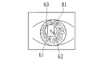
まず、角膜形状の測定について説明する。測定に当たり、モード切替スイッチ40によって角膜形状測定モードを選択する。検者は光源105に照明された被検眼の前眼部像をモニタ39により観察しながら、ジョイスティック4等の操作で測定部5のXYZ移動によってアライメントを行う。XY方向のアライメントは、光源34により角膜光学系で定まる光学中心(以下、角膜中心とするが、これはほぼ視軸中心として扱うこともできる。)に形成される指標像を、モニタ39に表示される照準マーカー60(図5参照)の中心に位置するようにする。モニタ39上の照準マーカー60は電気的に形成することができ、照準マーカー60の中心とCCDカメラ38の撮像光軸(測定光軸)は一致するように、予め調整されている。Z方向のアライメントは、位置検出素子117によって得られる作動距離方向の偏位情報に基づき、制御部50の制御によってモニタ39上に位置合わせのためのインジケータが表示されるので、検者はインジケータにしたがって本体部3をZ方向に移動して調整する。
【0028】
アライメントを完了させた後、測定スイッチ41が押されると、照明光源103が所定時間点灯されてプラチドリングが被検眼角膜に投影され、CCDカメラ38によって撮像された前眼部像が画像メモリ43に記憶される。角膜形状演算部53は画像メモリ43に記憶された画像を画像処理して、プラチドリング像のエッジ検出を行う。そして、所定の角度(1度)ステップ毎に角膜中心に対する各エッジ位置を得ることより角膜曲率分布を求める。
【0029】
また、アライメント状態を決定するアライメント状態演算部51は、測定スイッチ41が押されたときにCCDカメラ38によって検出されるアライメント指標像(光源34による角膜輝点)に基づき、装置の測定光軸L1に対するXY方向のアライメントの偏位情報を得る。アライメントの偏位情報は、プラチドリングが投影された前眼部像や角膜曲率の分布データと共にハードディスク等の記憶部45に記憶される。なお、角膜形状測定時のアライメントの偏位情報については、内側のプラチドリング像の中心を角膜中心位置として検出することも可能である。
【0030】
眼屈折力を測定する場合は、モード切替スイッチ40によって屈折力測定モードにする。眼屈折力測定では測定光束を眼内に入射させ、瞳孔を通過してくる眼底反射光を受光することにより行われる。ここで、一般に角膜中心と瞳孔中心は概ね一致するが、中には瞳孔中心が大きく偏心している被検眼もある。このような場合には、角膜中心を基準としたXY方向のアライメントでは測定光束が虹彩にけられ、測定に必要な反射光束が受光されずに、測定エラーが起こりやすい。
【0031】
検者はモニタ39に表示される前眼部像を観察し、瞳孔が角膜中心から偏心しているような場合は、瞳孔中心を基準にしてXY方向のアライメント調整を行う。すなわち、図5に示すように、モニタ39上の照準マーカー60の中心に被検眼の瞳孔中心が来るようにXY方向のアライメント調整を行う。Z方向はモニタ39上に表示されるインジケータにより予め合せておく。
【0032】
アライメント調整ができたら、検者は測定スイッチ41を押す。測定スイッチ41が押されると、CCDカメラ38で撮像された前眼部像が画像メモリ43に記憶されると共に、眼屈折力測定光学系120による眼屈折力測定が実行される。眼屈折力演算部52は、受光部135が持つ各受光素子からの出力信号の位相差に基づいて眼屈折力分布を得る。まず、従来の位相差法の屈折力と同様に予備測定を行い、その結果に基づいてレンズ28を移動して被検眼の雲霧を行う。その後、受光部135上でのスリット像の移動に伴って変化する受光素子136gと136hの出力信号から、受光素子136a〜136fが位置する経線方向での角膜中心(または視軸中心)を求める。次に、その中心に対する各受光素子136a〜136fの出力信号の位相差から、各受光素子に対応する角膜部位での屈折力を求める。スリット投影光学系121の回転セクター123と受光部135を所定の角度(1度)ステップで光軸回りに180度回転させながら、各角度ステップの経線毎にこの屈折力の演算を行うことにより、経線方向で変化する眼屈折力の分布を求める。この屈折力分布測定は、本出願人による特開平10−108837号公報と基本的に同じであるので、詳細はこれを参照されたい。
【0033】
また、測定スイッチ41が押されたときに、アライメント状態演算部51はCCDカメラ38によって検出されるアライメント指標像に基づき、角膜形状測定の時と同様に装置の光軸L1に対するXY方向のアライメントの偏位情報を得る。アライメントの偏位情報は、眼屈折力分布の測定結果と共に記憶部45に記憶される。
【0034】
以上のようにして同一被検眼における角膜曲率分布の測定データと眼屈折力分布の測定データが得られたら、モニタ39に表示される指示に従って、制御部50に接続されたキーボード58やマウス57を操作することにより、各測定データやアライメントの偏位情報がアブレーション量解析部54、モニタ表示制御部56に入力され、各測定データのマップ表示及び角膜切除量の演算結果がモニタ39上に表示される。
【0035】
各測定データのマップ表示について説明する。上述した眼屈折力分布の測定では、図5に示すように、瞳孔中心と角膜中心が偏心している場合を例にとり、瞳孔中心が照準マーカー60の中心に来るようにアライメントしている。そのため、角膜中心にできるアライメント指標像62は測定光軸の中心61からズレた位置となる。一方、角膜形状測定時には、アライメント指標像62が照準マーカー60の中心に来るようにアライメントして測定したので、測定光軸の中心61とアライメント指標像62はほぼ一致した状態となる。
【0036】
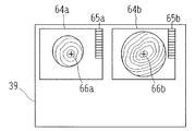
図6は従来の形式でカラーマップ表示したものであり、モニタ39上の同一画面左側に眼屈折力分布のマップ64aを、右側に角膜曲率分布のマップ64bを並べて表示している。従来の形式では、両方とも測定時の測定光軸中心が各エリアの表示中心を示す十字マーク66a、66bと一致されている。なお、図上の符号67a、67bで示す黒点はそれぞれ角膜中心位置を示し、説明の便宜上図示したものである。このような表示で、眼屈折力分布のマップ64aと角膜曲率分布のマップ64bとを見て両者の関係を比較する場合、角膜部位での2次元的な位置関係の対応が分かりにくい。
【0037】
そこで、本実施形態による各測定データに対するカラーマップ表示では、図7に示すように、アライメント指標像62の検出から得られる角膜中心位置を各マップ表示の中心である十字マーク66a、66bと一致させ、共通の表示基準の下に図形表示するように、モニタ表示制御部56によってモニタ39上の表示が制御される。すなわち、眼屈折力分布のマップ64aでは、角膜中心が十字マーク66aの中心に来るようにマップデータをアライメントの偏位分だけオフセットする。
【0038】
このような表示により、両測定データの2次元的な分布の位置関係の比較がしやすく、見易くなる。なお、図6、図7上の65a、64bは各マップ表示の色分けを示すカラーバーである。
【0039】
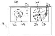
また、両測定データを位置合わせしたことにより、角膜上の同一位置での両測定データを容易に対応させて知ることができる。例えば、図8に示すように、マップ表示64a又は64b上の任意の一点68をマウス57でクリックすると、その点における測定値を両者同時に表示する。つまり、眼屈折力分布のマップ64aではその点での屈折力を表示し、角膜曲率分布のマップ64bではその点での角膜曲率あるいは角膜曲率から換算される角膜屈折力を同時に表示する。こうした表示に際しても、図6のように両者の位置関係の対応がとれてなくズレていると、同じポイントの測定値を表わしていることにはならない。
【0040】
また、アブレーション量解析部54は、眼屈折力分布データと角膜曲率分布データの角膜中心位置を2次元的に一致させて、屈折矯正手術のためのアブレーション量(角膜切除量)を求める。以下、その概略を説明する。
【0041】
まず、測定した角膜曲率から角膜三次元形状を求め、スネルの法則を用いて、角膜屈折力に変換する。次に、測定された眼屈折力分布のデータを角膜位置での眼屈折力分布のデータに変換する。これらにより、被検眼を正視とするに必要な屈折力を角膜屈折力の形式で表した値を求める。本明細書ではこれを「等価正視角膜屈折力」といい、
等価正視角膜屈折力=角膜屈折力+眼屈折力
で演算される。そして、この等価正視角膜屈折力の分布データを、スネルの法則を用いて角膜曲率の分布データ、すなわち、角膜の三次元形状データに変換する。最後に、角膜形状測定による角膜曲率から求まる三次元形状に対して、等価正視角膜屈折力を変換した角膜曲率分布から求まる三次元形状データを差引くことによりアブレーション量が算出される。演算された等価正視角膜屈折力の分布データも図7のようにカラーマップで図形表示され、アブレーション量は鳥瞰図等の3次元形状で図形表示される。
【0042】
求められたアブレーション量のデータは、通信ポート59bやフロッピィディスクドライブ59aに入れられたフロッピィディスクを介して角膜手術装置90側に出力され、角膜手術に利用される。
【0043】
このように異なるタイミングで測定された角膜形状測定データと眼屈折力分布測定データから、新たなデータである等価正視角膜屈折力やアブレーション量を算出するにあたっては、両測定データの2次元的位置を位置合わせすることで、正確な結果が得られる。
【0044】
また、上記ではアライメント指標像の位置によりXY方向のズレを補正したが、各測定時に得られる前眼部の撮像画像から瞳孔中心を求め、これを両測定データの2次元位置合わせの基準位置としても良い。瞳孔中心を求めるには、例えば撮影画像の画像処理により、瞳孔を縦線と横線で切り、その瞳孔のエッジとの交点を結ぶ線分のそれぞれの垂直二等分線の交点を瞳孔中心とする。また、画像処理により瞳孔の輪郭エッジを求めておいて、その内部領域の重心を瞳孔中心としても良い。
【0045】
以上、XY方向のズレ分を補正するように測定データの位置合わせをする例を説明したが、両測定において眼の回転角度(傾き角度)のアライメントずれがある場合には、この回転角度分についても補正して位置合わせすることが好ましい。眼の回転ずれの位置合わせ方法については、1例として以下のようにする。
【0046】
図9は、眼屈折力分布の測定時に撮影した前眼部像70と、角膜形状の測定時に撮影された前眼部像75とをモニタ39に同時に表示させた画面例であり、各前眼部像は測定時に画像メモリ43に記憶されたものである。なお、この例では両測定ともXY方向のアライメントは角膜中心にできたものとし、また、角膜形状の測定時に対して眼屈折力分布の測定時には眼(頭部)が傾いてしまったものとして説明する。
【0047】
検者は前眼部像70、75を観察して、虹彩の模様から両者に共通の特異点を見つけ、前眼部像70における2つの特異点71,72をマウス57でクリックし、特異点71,72を結ぶ線分73を引く。プラチドリング像が映った前眼部像75においても、左側の前眼部像70と一致する2つの特異点76,77をマウス57でクリックし、特異点76,77を結ぶ線分78を引く。この両者の線分73、78から両測定における眼の回転角度のアライメントずれを決定することができ、アライメント状態を決定するアライメント状態演算部51は回転角度のズレ量を求める。そして、先に示した図7や図8のように、眼屈折力分布のマップ64a、角膜曲率分布のマップ64bを表示する際には、回転角度のズレ分を補正して両者のマップの位置関係を合せるように、モニタ表示制御部56はモニタ39の表示制御を行う。
【0048】
また、等価正視角膜屈折力やアブレーション量の算出においても、アブレーション量解析部54は回転角度のズレ分を補正し、眼屈折力分布データと角膜曲率分布データの位置関係を一致させて演算を行う。
【0049】
なお、本実施の形態では特異点を虹彩の模様としたが、まつげの位置、鼻影等から定まる点としもよい。また、装置が画像解析により特異点を自動的に抽出することも可能である。
【0050】
(ロ)水晶体の調節力の解析動作
次に、遠方視での眼屈折力分布測定と近方視での眼屈折力分布測定を実行し、両者の測定データから水晶体の調節力を解析する場合について説明する。
【0051】
モード切替スイッチ40を押して遠/近眼屈折力分布測定モードにする。最初に、眼屈折力測定光学系120を用いて角膜切除量算出の測定と同様に、遠方視での眼屈折力分布測定をする。この場合、雲霧法にて測定しているため、このデータが眼の調節が解除された眼屈折力分布となる。また、測定時のアライメント状態は、前述と同様にアライメント指標像62の検出に基づいて、アライメント状態演算部51によってアライメントの偏位情報が得られ、測定結果と共に記憶部45に記憶される。
【0052】
次に、図2における固視光学系のレンズ28の位置を制御部50の制御により移動することによって、固視標29の像位置を所定距離の近方視状態にし、眼に調節負荷を与えた時の眼屈折力分布を測定する。例えば、先に測定した遠方眼屈折力のSE値(等価球面値)が−3Dであった場合、近方40cmを固視するには、固視標29の像が−3D−2.5D=−5.5Dに位置する様にレンズ28を移動させる。
【0053】
調節負荷を与える場合、瞳孔は縮瞳する傾向にあるので、アライメントは角膜中心で行えないケースがある。近方視での眼屈折力分布の測定では、先の例のように瞳孔中心でアライメントするものとする。このときのアライメントの偏位情報はアライメント状態演算部51によって得られ、測定結果と共に記憶部45に記憶される。
【0054】
遠方視及び近方視での眼屈折力分布の測定結果が得られると、調節力解析部55は遠方視での屈折力分布データと近方視での眼屈折力分布データとから、その差分の屈折力分布を演算する。眼は水晶体の厚みを変えることで遠くのものや近くのものに焦点を合わせるので、遠方視と近方視とでの眼屈折力分布の差から水晶体の屈折力変化を求めることができ、調節力の評価や診断に役立てることができる。このとき調節力解析部55は2つの屈折力分布データの位置関係をアライメントの偏位情報を基に一致させて演算することにより、2次元的な位置ずれの影響を取り除いて正確なデータを得ることができる。さらに、両測定の間で眼の回転が異なる場合には、これも前述と同様にして回転角度のズレを補正する。
【0055】
また、遠方視での眼屈折力分布、近方視での眼屈折力分布及びその差分の眼屈折力分布は、先の例と同じようにカラーマップでモニタ39の同一画面上に並べて表示される。この場合も、各マップの表示中心位置をアライメント基準である角膜中心に一致させて表示すると共に、回転角度の補正をした表示とすることにより、各マップにおける眼屈折力分布の状態の比較が正確に行える。
【0056】
以上の実施形態における眼屈折力分布の測定では、瞳孔中心にアライメントをする例を説明したが、角膜中心にアライメントする場合であっても、通常、多少の誤差を含むものであるので、上記のように各測定データの2次元的位置を合せることによって、その後の解析等をより正確に行うことができるようになる。
【0057】
また、以上の実施形態では眼屈折力分布測定と角膜形状測定の2つの測定機能が1つの装置に収まっている例としたが、これは別々の装置であっても良い。この場合、各測定装置による測定データ及びアライメント情報を外部コンピュータに入力し、外部コンピュータ側で2つの測定データの位置合わせを行って、表示や演算を行う。
【0058】
また、上記で説明した眼屈折力分布や角膜曲率分布の他、角膜厚み分布の測定データも2次元的位置合わせが必要な測定データの一つである。角膜厚み分布の測定は、以下の様に行なう。角膜に斜め方向からスリット光を入れ、スリット光を移動しながら正面からスリット断面像を連続撮影し、その画像から角膜前面カーブと角膜後面カーブを検出する。そして、角膜前面カーブと角膜後面カーブから角膜の任意位置での角膜厚さを求め、全域に渡って計算することで角膜厚さの分布を得る。あるいは、スリット光を正面から入れると共に、スリット光を角膜中心にして回転しながら、シャインプルーフの原理の基づいて斜め方向に配置されたカメラでスリット断面像を連続撮影し、その撮影画像を解析すことにより角膜厚さの分布を得ることができる。
【0059】
こうした角膜厚さの分布と先の実施形態で説明したアブレーション量の2次元的データを比較解析することにより、そのアブレーション量がその人の角膜厚さに対して適しているかを検討することが可能となる。この場合においても、各測定時におけるアライメント状態の決定結果を基に各データの2次元的位置を合わせることで、各データの比較や解析を正確に行なうことができる。
【0060】
【発明の効果】
以上説明したように、本発明によれば、異なるタイミングで測定されたデータの2次元的な位置合わせが可能となり、各データの比較や解析等を正確に、また容易に行なうことができる。
【図面の簡単な説明】
【図1】本形態の眼科装置の外観略図である。
【図2】測定部に配置される光学系の概略配置図である。
【図3】制御系の概略構成を示す図である。
【図4】眼屈折力測定光学系の受光部が有する受光素子の配置を示す図である。
【図5】眼屈折力測定のアライメント画面を示す図である。
【図6】眼屈折力測定と角膜曲率測定の解析画面を示す図である。
【図7】眼屈折力測定と角膜曲率測定において、アライメント指標像を基準位置として解析画面を示す図である。
【図8】眼屈折力測定と角膜曲率測定において、アライメント指標像を基準位置として、任意の一点を選択するとそれぞれのデータが同時に表示される画面を示す図である。
【図9】角度ズレ測定データの補正方法を説明する図である。
【符号の説明】
5 測定部
34 アライメント用光源
38 CCDカメラ
39 モニタ
43 画像メモリ
45 記憶部
50 制御部
51 アライメント状態演算部
52 眼屈折力演算部
53 角膜形状演算部
54 アブレーション量解析部
55 調節力解析部
56 モニタ表示制御部
59a フロッピィディスクドライブ
59b 通信ポート
61 測定光軸の中心
62 アライメント指標像
66a 十字マーク
66b 十字マーク
71、72、76、77 特異点
101 角膜形状測定用の光束を投光する光学系
121 スリット投影光学系
131 スリット像受光光学系
135 受光部[0001]
BACKGROUND OF THE INVENTION
The present invention relates to an ophthalmologic apparatus used in an ophthalmic clinic or an eyeglass store.
[0002]
[Prior art]
As an ophthalmologic apparatus, a corneal shape measuring apparatus is known that projects a placido ring onto a cornea, measures a distribution of curvature over a wide range of the cornea from a reflection image thereof, and visualizes the distribution as a topography. Japanese Patent Application Laid-Open No. 10-10883 proposes a device for obtaining refractive power distribution at a large number of sites on the cornea, and further calculates the amount of corneal resection used for refractive surgery from the measurement data of both. It has been proposed.
[0003]
[Problems to be solved by the invention]
However, when new data is obtained from measurement data measured at different timings as described above, or when the relationship between each measurement data is examined, if the two-dimensional positional relationship between each measurement data does not correspond, Results are difficult to obtain and comparison is not easy.
[0004]
The present invention provides an ophthalmologic apparatus that enables alignment of a plurality of measurement data measured at different timings, and allows easy and accurate comparison and analysis of each measurement data. And
[0005]
[Means for Solving the Problems]
In order to solve the above problems, the present invention is characterized by having the following configuration.
[0006]
(1) The eye to be examined is two-dimensional As changing distribution data First input means for inputting first measurement data obtained by the first measurement means for measuring, and the eye to be examined in two dimensions As changing distribution data A captured image including second input means for inputting second measurement data obtained by the second measurement means for measurement, and an anterior segment obtained at the time of measurement by the first measurement means. To determine the center of the cornea or the center of the pupil as the first measurement data alignment reference and use the obtained first measurement data alignment reference as a reference First measurement data And processing the captured image including the anterior segment obtained at the time of measurement by the second measuring means to obtain a second measurement data alignment reference corresponding to the first measurement data alignment reference, Based on data alignment criteria Second measurement data When And data alignment means for aligning.
(2) First input means for inputting the first measurement data obtained by the first measurement means for measuring the eye to be examined as distribution data that changes two-dimensionally, and a first input for measuring the eye to be examined as distribution data that changes two-dimensionally. An anterior eye from among the captured images including the second input means for inputting the second measurement data obtained by the two measurement means, and the anterior eye portion obtained at the time of each measurement of the first measurement means and the second measurement data. Data alignment means for aligning the first measurement data and the second measurement data based on a common singular point of the partial image. Features.
(3) First input means for inputting the first measurement data obtained by the first measurement means for measuring the eye to be examined as distribution data that changes two-dimensionally, and a first input for measuring the eye to be examined as distribution data that changes two-dimensionally. A second input means for inputting second measurement data obtained by the two measurement means, and a rotational deviation based on a captured image including the first measurement means and the anterior segment obtained during each measurement of the second measurement data. And data alignment means for aligning the first measurement data and the second measurement data. .
[0015]
DETAILED DESCRIPTION OF THE INVENTION
Hereinafter, embodiments of the present invention will be described with reference to the drawings. FIG. 1 is a schematic external view of an ophthalmic apparatus according to the present invention. FIG. 1A is a front view of a subject, and FIG. 1B is a side view.
[0016]
[0017]
[0018]
FIG. 2 is a diagram showing an optical system housed in the measurement unit 5. An
[0019]
Behind the
[0020]
An eye refractive power measurement
[0021]
The slit image light receiving
[0022]
In the eye refractive power measurement
[0023]
On the optical axis L3 that is coaxial with the optical axis L1 by the
[0024]
A
[0025]
A
[0026]
Next, the operation of the apparatus will be described using the block diagram of the control system shown in FIG. This apparatus has a function of performing corneal shape measurement and eye refractive power measurement, and analyzing the amount of corneal resection for refractive surgery from both measurement data. In addition, the eye refractive power distribution (eye refractive power distribution in distant vision) in which the eye's accommodation power has been released, and the eye refractive power distribution (eye refractive power distribution in near vision) when an adjustment is applied to the eye And has a function of analyzing the adjusting power of the lens.
[0027]
(B) Analyzing operation of corneal resection
First, measurement of the corneal shape will be described. In measurement, the
[0028]
After the alignment is completed, when the
[0029]
The alignment
[0030]
When measuring the eye refractive power, the
[0031]
The examiner observes the anterior segment image displayed on the
[0032]
When the alignment is adjusted, the examiner presses the
[0033]
Further, when the
[0034]
When the measurement data of the corneal curvature distribution and the measurement data of the eye refractive power distribution in the same eye to be examined are obtained as described above, the
[0035]
A map display of each measurement data will be described. In the above-described measurement of the refractive power distribution of the eye, as shown in FIG. 5, the case where the center of the pupil and the center of the cornea are decentered is taken as an example, and alignment is performed so that the center of the pupil is at the center of the aiming
[0036]
FIG. 6 shows a color map display in a conventional format, in which an eye refractive
[0037]
Therefore, in the color map display for each measurement data according to the present embodiment, as shown in FIG. 7, the corneal center position obtained from the detection of the
[0038]
Such a display makes it easy to compare the positional relationship between the two-dimensional distributions of the two measurement data, making it easy to see. In addition, 65a and 64b on FIG. 6, FIG. 7 are the color bars which show the color classification of each map display.
[0039]
Further, by aligning both measurement data, it is possible to easily know both measurement data at the same position on the cornea. For example, as shown in FIG. 8, when an
[0040]
In addition, the ablation
[0041]
First, a three-dimensional shape of the cornea is obtained from the measured corneal curvature, and converted into corneal refractive power using Snell's law. Next, the measured eye refractive power distribution data is converted into eye refractive power distribution data at the cornea position. As a result, a value representing the refractive power necessary for making the subject's eye normal is expressed in the form of corneal refractive power. In this specification, this is referred to as “equivalent normal corneal refractive power”,
Equivalent normal vision corneal refractive power = corneal refractive power + eye refractive power
Calculated with Then, this equivalent normal vision corneal refractive power distribution data is converted into corneal curvature distribution data, that is, three-dimensional shape data of the cornea using Snell's law. Finally, the ablation amount is calculated by subtracting the three-dimensional shape data obtained from the corneal curvature distribution obtained by converting the equivalent normal corneal refractive power from the three-dimensional shape obtained from the corneal curvature obtained by measuring the corneal shape. The calculated distribution data of the equivalent normal corneal refractive power is also displayed graphically as a color map as shown in FIG. 7, and the ablation amount is graphically displayed in a three-dimensional shape such as a bird's eye view.
[0042]
The obtained ablation amount data is output to the
[0043]
In calculating the equivalent normal vision corneal refractive power and the amount of ablation, which are new data, from the corneal shape measurement data and the eye refractive power distribution measurement data measured at different timings as described above, the two-dimensional position of both measurement data is determined. By aligning, accurate results can be obtained.
[0044]
In the above description, the displacement in the X and Y directions is corrected based on the position of the alignment index image. However, the center of the pupil is obtained from the captured image of the anterior segment obtained at each measurement, and this is used as the reference position for two-dimensional alignment of both measurement data Also good. In order to obtain the pupil center, for example, by performing image processing of the captured image, the pupil is cut by a vertical line and a horizontal line, and the intersection of each perpendicular bisector connecting the intersection with the edge of the pupil is set as the pupil center. . Further, the contour edge of the pupil is obtained by image processing, and the center of gravity of the inner region may be used as the pupil center.
[0045]
As described above, the example in which the measurement data is aligned so as to correct the deviation in the XY direction has been described. However, when there is a misalignment of the rotation angle (tilt angle) of the eye in both measurements, It is preferable to correct and align the position. As an example, a method for aligning the rotational deviation of the eye is as follows.
[0046]
FIG. 9 is an example of a screen in which an
[0047]
The examiner observes the
[0048]
Also, in calculating the equivalent normal corneal refractive power and the ablation amount, the ablation
[0049]
In the present embodiment, the singular point is an iris pattern, but may be a point determined from the position of the eyelashes, the nose shadow, or the like. It is also possible for the apparatus to automatically extract singular points by image analysis.
[0050]
(B) Analyzing motion of lens accommodation
Next, the case where the eye refractive power distribution measurement in the far vision and the eye refractive power distribution measurement in the near vision are executed and the adjustment power of the lens is analyzed from the measurement data of both will be described.
[0051]
The
[0052]
Next, by moving the position of the
[0053]
When an adjustment load is applied, there is a case where alignment cannot be performed at the center of the cornea because the pupil tends to contract. In the measurement of the eye refractive power distribution in near vision, alignment is performed at the center of the pupil as in the previous example. The alignment deviation information at this time is obtained by the alignment
[0054]
When the measurement result of the eye refractive power distribution in the far vision and the near vision is obtained, the accommodation
[0055]
Further, the eye refractive power distribution in the far vision, the eye refractive power distribution in the near vision, and the difference eye refractive power distribution are displayed side by side on the same screen of the
[0056]
In the measurement of the eye refractive power distribution in the above embodiment, the example in which alignment is performed at the center of the pupil has been described. However, even when alignment is performed at the center of the cornea, it usually includes some error, so that By matching the two-dimensional position of each measurement data, subsequent analysis and the like can be performed more accurately.
[0057]
In the above embodiment, the two measurement functions of the eye refractive power distribution measurement and the corneal shape measurement are included in one apparatus, but they may be separate apparatuses. In this case, measurement data and alignment information obtained by each measurement apparatus are input to an external computer, and the two computer data are aligned on the external computer side for display and calculation.
[0058]
In addition to the eye refractive power distribution and the corneal curvature distribution described above, the measurement data of the corneal thickness distribution is one of the measurement data that requires two-dimensional alignment. The corneal thickness distribution is measured as follows. Slit light is incident on the cornea from an oblique direction, and a slit cross-sectional image is continuously photographed from the front while moving the slit light, and a front cornea curve and a back cornea curve are detected from the images. Then, the corneal thickness at an arbitrary position of the cornea is obtained from the corneal front curve and the corneal back curve, and the corneal thickness distribution is obtained by calculating over the entire area. Alternatively, slit light is entered from the front, and the slit cross-sectional image is continuously photographed with a camera arranged in an oblique direction based on the Schein-proof principle while rotating the slit light around the cornea, and the photographed image is analyzed. Thus, the distribution of corneal thickness can be obtained.
[0059]
By comparing and analyzing the two-dimensional data of the corneal thickness distribution and the ablation amount described in the previous embodiment, it is possible to examine whether the ablation amount is suitable for the corneal thickness of the person. It becomes. Even in this case, the comparison and analysis of each data can be performed accurately by matching the two-dimensional positions of each data based on the determination result of the alignment state at the time of each measurement.
[0060]
【The invention's effect】
As described above, according to the present invention, two-dimensional alignment of data measured at different timings is possible, and comparison and analysis of each data can be performed accurately and easily.
[Brief description of the drawings]
FIG. 1 is a schematic external view of an ophthalmologic apparatus of the present embodiment.
FIG. 2 is a schematic arrangement diagram of an optical system arranged in a measurement unit.
FIG. 3 is a diagram showing a schematic configuration of a control system.
FIG. 4 is a diagram illustrating an arrangement of light receiving elements included in a light receiving unit of an eye refractive power measurement optical system.
FIG. 5 is a diagram showing an alignment screen for eye refractive power measurement.
FIG. 6 is a diagram showing an analysis screen for eye refractive power measurement and corneal curvature measurement.
FIG. 7 is a diagram showing an analysis screen with an alignment index image as a reference position in eye refractive power measurement and corneal curvature measurement.
FIG. 8 is a diagram showing a screen on which each data is simultaneously displayed when an arbitrary point is selected with an alignment index image as a reference position in eye refractive power measurement and corneal curvature measurement.
FIG. 9 is a diagram illustrating a method of correcting angle deviation measurement data.
[Explanation of symbols]
5 Measurement section
34 Light source for alignment
38 CCD camera
39 Monitor
43 Image memory
45 storage unit
50 Control unit
51 Alignment state calculator
52 Eye refractive power calculator
53 Corneal shape calculator
54 Ablation amount analysis part
55 Adjustability analysis part
56 Monitor display controller
59a floppy disk drive
59b Communication port
61 Center of measurement optical axis
62 Alignment index image
66a cross mark
66b cross mark
71, 72, 76, 77 Singularity
101 Optical system for projecting a light beam for corneal shape measurement
121 Slit projection optical system
131 Slit image receiving optical system
135 Receiver
Claims (3)
Priority Applications (4)
| Application Number | Priority Date | Filing Date | Title |
|---|---|---|---|
| JP2000086475A JP3664937B2 (en) | 2000-03-27 | 2000-03-27 | Ophthalmic equipment |
| EP01107502A EP1138257B1 (en) | 2000-03-27 | 2001-03-26 | Ophthalmic apparatus |
| DE60105874T DE60105874T2 (en) | 2000-03-27 | 2001-03-26 | Ophthalmic device |
| US09/817,272 US6655805B2 (en) | 2000-03-27 | 2001-03-27 | Ophthalmic apparatus |
Applications Claiming Priority (1)
| Application Number | Priority Date | Filing Date | Title |
|---|---|---|---|
| JP2000086475A JP3664937B2 (en) | 2000-03-27 | 2000-03-27 | Ophthalmic equipment |
Publications (3)
| Publication Number | Publication Date |
|---|---|
| JP2001269317A JP2001269317A (en) | 2001-10-02 |
| JP2001269317A5 JP2001269317A5 (en) | 2005-03-03 |
| JP3664937B2 true JP3664937B2 (en) | 2005-06-29 |
Family
ID=18602639
Family Applications (1)
| Application Number | Title | Priority Date | Filing Date |
|---|---|---|---|
| JP2000086475A Expired - Lifetime JP3664937B2 (en) | 2000-03-27 | 2000-03-27 | Ophthalmic equipment |
Country Status (4)
| Country | Link |
|---|---|
| US (1) | US6655805B2 (en) |
| EP (1) | EP1138257B1 (en) |
| JP (1) | JP3664937B2 (en) |
| DE (1) | DE60105874T2 (en) |
Cited By (1)
| Publication number | Priority date | Publication date | Assignee | Title |
|---|---|---|---|---|
| JP2011508618A (en) * | 2007-12-21 | 2011-03-17 | カール ツァイス サージカル ゲーエムベーハー | Method for detecting and / or tracking the location of characteristic eye components |
Families Citing this family (42)
| Publication number | Priority date | Publication date | Assignee | Title |
|---|---|---|---|---|
| US7431455B2 (en) * | 2005-03-22 | 2008-10-07 | Amo Manufacturing Usa, Llc | Pupilometer for pupil center drift and pupil size measurements at differing viewing distances |
| JP4837840B2 (en) * | 2001-06-01 | 2011-12-14 | 株式会社ニデック | Corneal resection data determination device and corneal resection data determination program |
| JP4694069B2 (en) * | 2001-09-28 | 2011-06-01 | 株式会社トプコン | Ophthalmic equipment |
| EP1435832B1 (en) * | 2001-10-17 | 2014-03-26 | Carl Zeiss Meditec AG | Method and apparatus for measuring a corneal profile of an eye |
| WO2003101355A1 (en) | 2002-05-31 | 2003-12-11 | Carl Zeiss Meditec Ag | Method for controlling a device for treating the human eye |
| JP4162450B2 (en) * | 2002-08-29 | 2008-10-08 | 株式会社ニデック | Cornea surgery device |
| JP4086667B2 (en) | 2003-01-15 | 2008-05-14 | 株式会社ニデック | Cornea surgery device |
| DE20313745U1 (en) | 2003-09-02 | 2003-11-20 | Oculus Optikgeraete Gmbh | Ophthalmological analysis system |
| JP4492858B2 (en) * | 2004-07-20 | 2010-06-30 | 株式会社ニデック | Ophthalmic apparatus and intraocular refractive power distribution calculation program |
| JP4501007B2 (en) * | 2004-08-26 | 2010-07-14 | 国立大学法人名古屋大学 | Optical coherence tomography device |
| US7365856B2 (en) | 2005-01-21 | 2008-04-29 | Carl Zeiss Meditec, Inc. | Method of motion correction in optical coherence tomography imaging |
| JP4578995B2 (en) * | 2005-02-04 | 2010-11-10 | 株式会社ニデック | Ophthalmic measuring device |
| US7805009B2 (en) | 2005-04-06 | 2010-09-28 | Carl Zeiss Meditec, Inc. | Method and apparatus for measuring motion of a subject using a series of partial images from an imaging system |
| US20070019161A1 (en) * | 2005-07-21 | 2007-01-25 | Clausing Robert C | Eye measurement system providing for integration of elevation data and pachymetry data |
| JP5028073B2 (en) | 2006-11-29 | 2012-09-19 | 株式会社ニデック | Cornea surgery device |
| JP5179063B2 (en) * | 2007-01-06 | 2013-04-10 | 株式会社ニデック | Ophthalmic equipment |
| JP4937792B2 (en) * | 2007-03-01 | 2012-05-23 | 株式会社ニデック | Fundus camera |
| JP4916935B2 (en) * | 2007-03-30 | 2012-04-18 | 株式会社ニデック | Ophthalmic equipment |
| ITRM20070183A1 (en) | 2007-04-03 | 2008-10-04 | Optikon 2000 Spa | OPHTHALMOLOGICAL MULTIFUNCTION APPARATUS. |
| US8016420B2 (en) * | 2007-05-17 | 2011-09-13 | Amo Development Llc. | System and method for illumination and fixation with ophthalmic diagnostic instruments |
| ATE512619T1 (en) * | 2008-05-07 | 2011-07-15 | Optopol Technology Spolka Akcyjna | OPTICAL DEVICE FOR CHECKING EYES AND METHOD FOR CHECKING EYES USING THE OPTICAL DEVICE |
| JP5144579B2 (en) * | 2009-04-02 | 2013-02-13 | 株式会社トプコン | Ophthalmic observation device |
| US20120240939A1 (en) * | 2011-03-24 | 2012-09-27 | Jochen Kandulla | Apparatus and Method for Control of Refractive Index Changes in a Material |
| US9033510B2 (en) | 2011-03-30 | 2015-05-19 | Carl Zeiss Meditec, Inc. | Systems and methods for efficiently obtaining measurements of the human eye using tracking |
| US8857988B2 (en) | 2011-07-07 | 2014-10-14 | Carl Zeiss Meditec, Inc. | Data acquisition methods for reduced motion artifacts and applications in OCT angiography |
| JP6143447B2 (en) * | 2011-12-21 | 2017-06-07 | キヤノン株式会社 | Ophthalmic apparatus, eye measurement method, and program |
| US9101294B2 (en) | 2012-01-19 | 2015-08-11 | Carl Zeiss Meditec, Inc. | Systems and methods for enhanced accuracy in OCT imaging of the cornea |
| JP5179675B2 (en) * | 2012-02-20 | 2013-04-10 | 株式会社ニデック | Ophthalmic equipment |
| CA2968687C (en) * | 2012-02-24 | 2017-10-24 | Noel Ami Alpins | Assessment of topographic semi-meridian parameters for corneal astigmatism analysis and vector planning treatment |
| JP6049310B2 (en) | 2012-06-01 | 2016-12-21 | キヤノン株式会社 | Imaging apparatus, control method, and program |
| JP2013248254A (en) * | 2012-06-01 | 2013-12-12 | Canon Inc | Ophthalmic device |
| JP6049309B2 (en) | 2012-06-01 | 2016-12-21 | キヤノン株式会社 | Measuring device, ophthalmic imaging device, control method, and program |
| JP6041540B2 (en) | 2012-06-01 | 2016-12-07 | キヤノン株式会社 | Ophthalmic equipment |
| JP6041539B2 (en) | 2012-06-01 | 2016-12-07 | キヤノン株式会社 | Ophthalmic equipment |
| JP6041538B2 (en) | 2012-06-01 | 2016-12-07 | キヤノン株式会社 | Ophthalmic equipment |
| JP6411792B2 (en) | 2014-06-27 | 2018-10-24 | 株式会社トプコン | Regulatory function evaluation device |
| IL303125B1 (en) * | 2015-05-20 | 2024-03-01 | Magic Leap Inc | Tilt shift iris imaging |
| US11382505B2 (en) * | 2016-04-29 | 2022-07-12 | Consejo Superior De Investigaciones Cientificas | Method of estimating a full shape of the crystalline lens from measurements taken by optic imaging techniques and method of estimating an intraocular lens position in a cataract surgery |
| JP6654657B2 (en) * | 2018-04-25 | 2020-02-26 | 株式会社トプコン | Adjustment function evaluation device |
| JP7100503B2 (en) | 2018-06-15 | 2022-07-13 | 株式会社トプコン | Ophthalmic equipment |
| DE102019101409B4 (en) | 2019-01-21 | 2021-12-30 | Oculus Optikgeräte GmbH | Procedure and vision testing system for examining eyes |
| WO2023047626A1 (en) * | 2021-09-21 | 2023-03-30 | ソニーグループ株式会社 | Image processing device, image processing method, and surgical microscope system |
Family Cites Families (5)
| Publication number | Priority date | Publication date | Assignee | Title |
|---|---|---|---|---|
| JP3441159B2 (en) * | 1994-04-15 | 2003-08-25 | 株式会社ニデック | Ophthalmic equipment |
| JP3461957B2 (en) * | 1995-02-28 | 2003-10-27 | 株式会社ニデック | Ophthalmic equipment |
| EP0836830B1 (en) * | 1996-10-03 | 2004-06-30 | Nidek Co., Ltd | Ophthalmic refraction measurement apparatus |
| JP3523453B2 (en) * | 1997-06-30 | 2004-04-26 | 株式会社ニデック | Optometrist |
| DE69931419T2 (en) * | 1998-03-31 | 2006-12-28 | Nidek Co., Ltd., Gamagori | Ophthalmic device |
-
2000
- 2000-03-27 JP JP2000086475A patent/JP3664937B2/en not_active Expired - Lifetime
-
2001
- 2001-03-26 DE DE60105874T patent/DE60105874T2/en not_active Expired - Lifetime
- 2001-03-26 EP EP01107502A patent/EP1138257B1/en not_active Expired - Lifetime
- 2001-03-27 US US09/817,272 patent/US6655805B2/en not_active Expired - Lifetime
Cited By (1)
| Publication number | Priority date | Publication date | Assignee | Title |
|---|---|---|---|---|
| JP2011508618A (en) * | 2007-12-21 | 2011-03-17 | カール ツァイス サージカル ゲーエムベーハー | Method for detecting and / or tracking the location of characteristic eye components |
Also Published As
| Publication number | Publication date |
|---|---|
| JP2001269317A (en) | 2001-10-02 |
| EP1138257B1 (en) | 2004-09-29 |
| US20010024265A1 (en) | 2001-09-27 |
| DE60105874T2 (en) | 2005-10-06 |
| DE60105874D1 (en) | 2004-11-04 |
| EP1138257A1 (en) | 2001-10-04 |
| US6655805B2 (en) | 2003-12-02 |
Similar Documents
| Publication | Publication Date | Title |
|---|---|---|
| JP3664937B2 (en) | Ophthalmic equipment | |
| JP3709335B2 (en) | Ophthalmic equipment | |
| JP3978024B2 (en) | Ophthalmic device and corneal surgery device | |
| EP0947158B1 (en) | Ophthalmic apparatus | |
| US5870167A (en) | Apparatus and method for imaging anterior structures of the eye | |
| JP3523453B2 (en) | Optometrist | |
| JP4723780B2 (en) | Corneal resection amount determination device and corneal surgery device | |
| US7316480B2 (en) | Eye refractive power measurement apparatus | |
| JP3630884B2 (en) | Ophthalmic examination equipment | |
| JP3539829B2 (en) | Ophthalmic measurement device | |
| JP3798199B2 (en) | Ophthalmic equipment | |
| JP3703310B2 (en) | Hand-held ophthalmic device | |
| EP1057446B1 (en) | Corneal shape measuring apparatus | |
| EP1317899B1 (en) | Shape measurement apparatus | |
| JP4987408B2 (en) | Ophthalmic equipment | |
| US6547392B2 (en) | Ophthalmic apparatus | |
| JP3636917B2 (en) | Eye refractive power measurement device | |
| JP4481537B2 (en) | Cornea surgery device | |
| JP3693493B2 (en) | Ophthalmic equipment | |
| JP3916335B2 (en) | Corneal resection amount determination device and corneal surgery device | |
| JP4288139B2 (en) | Ophthalmic measuring device | |
| JPH06189905A (en) | Ophthalmologic optical measuring device | |
| JP4745550B2 (en) | Corneal measuring device | |
| JP4653576B2 (en) | Eye refractive power measuring device | |
| JPH0554325B2 (en) |
Legal Events
| Date | Code | Title | Description |
|---|---|---|---|
| A521 | Request for written amendment filed |
Free format text: JAPANESE INTERMEDIATE CODE: A523 Effective date: 20040401 |
|
| A621 | Written request for application examination |
Free format text: JAPANESE INTERMEDIATE CODE: A621 Effective date: 20040401 |
|
| A977 | Report on retrieval |
Free format text: JAPANESE INTERMEDIATE CODE: A971007 Effective date: 20041118 |
|
| A131 | Notification of reasons for refusal |
Free format text: JAPANESE INTERMEDIATE CODE: A131 Effective date: 20041130 |
|
| A521 | Request for written amendment filed |
Free format text: JAPANESE INTERMEDIATE CODE: A523 Effective date: 20050131 |
|
| TRDD | Decision of grant or rejection written | ||
| A01 | Written decision to grant a patent or to grant a registration (utility model) |
Free format text: JAPANESE INTERMEDIATE CODE: A01 Effective date: 20050302 |
|
| A61 | First payment of annual fees (during grant procedure) |
Free format text: JAPANESE INTERMEDIATE CODE: A61 Effective date: 20050330 |
|
| R150 | Certificate of patent or registration of utility model |
Ref document number: 3664937 Country of ref document: JP Free format text: JAPANESE INTERMEDIATE CODE: R150 Free format text: JAPANESE INTERMEDIATE CODE: R150 |
|
| FPAY | Renewal fee payment (event date is renewal date of database) |
Free format text: PAYMENT UNTIL: 20080408 Year of fee payment: 3 |
|
| FPAY | Renewal fee payment (event date is renewal date of database) |
Free format text: PAYMENT UNTIL: 20090408 Year of fee payment: 4 |
|
| FPAY | Renewal fee payment (event date is renewal date of database) |
Free format text: PAYMENT UNTIL: 20090408 Year of fee payment: 4 |
|
| FPAY | Renewal fee payment (event date is renewal date of database) |
Free format text: PAYMENT UNTIL: 20100408 Year of fee payment: 5 |
|
| FPAY | Renewal fee payment (event date is renewal date of database) |
Free format text: PAYMENT UNTIL: 20100408 Year of fee payment: 5 |
|
| FPAY | Renewal fee payment (event date is renewal date of database) |
Free format text: PAYMENT UNTIL: 20110408 Year of fee payment: 6 |
|
| FPAY | Renewal fee payment (event date is renewal date of database) |
Free format text: PAYMENT UNTIL: 20120408 Year of fee payment: 7 |
|
| FPAY | Renewal fee payment (event date is renewal date of database) |
Free format text: PAYMENT UNTIL: 20120408 Year of fee payment: 7 |
|
| FPAY | Renewal fee payment (event date is renewal date of database) |
Free format text: PAYMENT UNTIL: 20130408 Year of fee payment: 8 |
|
| FPAY | Renewal fee payment (event date is renewal date of database) |
Free format text: PAYMENT UNTIL: 20130408 Year of fee payment: 8 |
|
| FPAY | Renewal fee payment (event date is renewal date of database) |
Free format text: PAYMENT UNTIL: 20140408 Year of fee payment: 9 |
|
| S531 | Written request for registration of change of domicile |
Free format text: JAPANESE INTERMEDIATE CODE: R313531 |
|
| R350 | Written notification of registration of transfer |
Free format text: JAPANESE INTERMEDIATE CODE: R350 |
|
| R250 | Receipt of annual fees |
Free format text: JAPANESE INTERMEDIATE CODE: R250 |
|
| R250 | Receipt of annual fees |
Free format text: JAPANESE INTERMEDIATE CODE: R250 |
|
| R250 | Receipt of annual fees |
Free format text: JAPANESE INTERMEDIATE CODE: R250 |
|
| EXPY | Cancellation because of completion of term |