JP3663205B2 - Processing method of subscriber information in connectionless data service - Google Patents
Processing method of subscriber information in connectionless data service Download PDFInfo
- Publication number
- JP3663205B2 JP3663205B2 JP2004169182A JP2004169182A JP3663205B2 JP 3663205 B2 JP3663205 B2 JP 3663205B2 JP 2004169182 A JP2004169182 A JP 2004169182A JP 2004169182 A JP2004169182 A JP 2004169182A JP 3663205 B2 JP3663205 B2 JP 3663205B2
- Authority
- JP
- Japan
- Prior art keywords
- source address
- information
- compressed
- address
- charging information
- Prior art date
- Legal status (The legal status is an assumption and is not a legal conclusion. Google has not performed a legal analysis and makes no representation as to the accuracy of the status listed.)
- Expired - Fee Related
Links
Images


Landscapes
- Meter Arrangements (AREA)
- Data Exchanges In Wide-Area Networks (AREA)
Description
本発明は、LAN間接続を実現する目的などのために構築される広帯域のコネクションレスデータサービスに関し、更に詳しくは、そのようなサービスにおける加入者情報の処理方式に関する。 The present invention relates to a broadband connectionless data service constructed for the purpose of realizing a connection between LANs, and more particularly to a method of processing subscriber information in such a service.
LAN間接続を実現する目的などのために構築される広帯域のコネクションレスデータサービスとして、例えば、SMDS ( switched multi-megabit data service)が知られている。 For example, SMDS (switched multi-megabit data service) is known as a broadband connectionless data service constructed for the purpose of realizing connection between LANs.
広帯域のコネクションレスデータサービスは、非常に多くの加入者のコネクションレスデータを処理するため、加入者情報をいかに効率良く処理するかが重要である。
図8に、SMDSシステムの一般的な構成図を示す。Since a broadband connectionless data service processes connectionless data of a very large number of subscribers, it is important how efficiently the subscriber information is processed.
FIG. 8 shows a general configuration diagram of the SMDS system.
SMDSは、ATM(非同期転送モード)方式に基づくコネクションレスデータサービスである。
加入者からの情報は、SNI(Subscriber Network Interface)に基づいて処理される。そして、加入者には、物理伝送路として、例えば1.5Mbpの伝送速度を有するDS1加入者線801及び45Mbpsの伝送速度を有するDS3加入者線803が提供される。DS1加入者線801はDS1終端部802に、DS3加入者線803はDS3終端部804に、それぞれ終端される。SMDS is a connectionless data service based on the ATM (Asynchronous Transfer Mode) system.
Information from the subscriber is processed based on SNI (Subscriber Network Interface). The subscriber is provided with, for example, a
SMDSを利用して通信が行われる場合、加入者からのセルには、SMDSに対応する半固定のVCI(仮想チャネル識別子)及びVPI(仮想パス識別子)が付与されている。DS1終端部802及びDS3終端部804は、この半固定のVCI+VPIが付与されているセルを抽出して、そのセルのVCI+VPIを、それぞれの終端部に対応する半固定のVCI+VPIに付け替え、そのセルをスイッチ部808に向けて出力する。 When communication is performed using SMDS, a semi-fixed VCI (virtual channel identifier) and VPI (virtual path identifier) corresponding to SMDS are assigned to a cell from a subscriber. The
このセルは、マルチプレクサ/デマルチプレクサ805、806、又は807を介してスイッチ部808へ入力される。スイッチ部808は、各DS1終端部802又はDS3終端部804に対応する半固定のVCI+VPIが付与されたセルを、SMDSメッセージハンドラ(SMDS−MH)813に転送する。 This cell is input to the
SMDS−MH813は、622Mbpsの伝送速度を有するハイウエイ816によりスイッチ部808と接続される。このSMDS−MH813には、インタフェース814とラインプロセッサ(LP)815とから構成され、155Mbpsの処理能力を有するメッセージシェルフ(MESH)を、最大4つまで含めることができる。1つのLP815は、それが含まれる局が収容する最大で32本のDS1加入者線801上の加入者情報を扱うことができる。従って、1つのSMDS−MH813は、32×4=128本のDS1加入者線801上の加入者情報を扱うことができる。そして、局の規模に応じた数のSMDS−MH813が、ハイウエイ816を介してスイッチ部808に接続される。 The SMDS-MH 813 is connected to the
LP815は、受信したセルに付与されている半固定のVCI+VPIを判別することにより、そのセルがどのDS1終端部802又はDS3終端部804から入力されたかを認識することができる。そして、LP815は、複数のセルを使って転送されてきたメッセージ(パケット)から、発信元アドレスSAを抽出し、そのアドレスに対応する縮退された発信元アドレスを算出する。また、LP815は、上述のメッセージから、宛先アドレスDAを抽出する。そして、上述した宛先アドレスDAが局内宛てのものである場合には、LP815は、上述のメッセージが格納される各セルのVCI+VPIを、その宛先アドレスDAに対応する局内のDS1終端部802又はDS3終端部804の半固定のVCI+VPIに付け替える。一方、上述した宛先アドレスDAが局外宛てのものである場合には、LP815は、宛先局のSMDS MHを算出した後、上述のメッセージが格納される各セルのVCI+VPIを、上述の縮退された発信元アドレスと宛先局のSMDS−MH813に対応するVCI+VPIに付け替える。これらの処理と共に、LP815は、上述したメッセージが格納されている各セルの先頭に、各セルがスイッチ部808内で自律的にスイッチされるように、ATM方式に特有の情報であるタグと呼ばれる情報を付与する。その後、LP815は、各セルを、インタフェース814及びハイウエイ816を介して、再びスイッチ部808へ出力する。 The
スイッチ部808内の特には図示しない各スイッチモジュールは、入力したセルを、そのセルの先頭に付与されているタグの値を判別しながら、高速にスイッチする。
この場合、SMDS−MH813から入力されたセルは、それが局内宛てのものである場合には、そのセルに付加されているタグに基づいてスイッチ部808で自律的に交換された後、マルチプレクサ/デマルチプレクサ807、806、又は805を介して、DS1終端部802又はDS3終端部804、及びDS1加入者線801又はDS3加入者線803を介し、局内の加入者に転送される。また、そのセルは、それが局外宛てものである場合には、そのセルに付加されているタグに基づいてスイッチ部808で自律的に交換された後に、マルチプレクサ/デマルチプレクサ810、終端回路(FINF)811、及び局間中継線812を介して、宛先局のSMDS−MH813に転送される。Each switch module (not shown) in the
In this case, when the cell input from SMDS-MH813 is addressed to the inside of the station, the cell is autonomously exchanged by the
宛先局のSMDS−MH813内のLP815は、それが受信した複数のセルを使って転送されてきたメッセージの宛先アドレスDAを判別することによりそのメッセージが局内宛てのものであることを認識した後に、そのメッセージが格納されている各セルのVCI+VPIを、上述の宛先アドレスDAに対応する局内のDS1終端部802又はDS3終端部804の半固定のVCI+VPIに付け替える。そして、LP815は、上述のメッセージが格納されている各セルの先頭に、各セルが局内のスイッチ部内で自律的にスイッチされるようにタグを付与した後、各セルをスイッチ部へ出力する。これらの各セルは、各セルに付加されているタグに基づいてスイッチ部で自律的に交換された後に、DS1終端部802又はDS3終端部804、及びDS1加入者線801又はDS3加入者線803を介して、その局内の加入者に転送される。 After the
以上のように、図8のDS1加入者線801を終端するDS1終端部802又はDS3加入者線803を終端するDS3終端部804が、加入者情報を個別に処理するのではなく、SMDS−MH813が全ての加入者情報をまとめて処理することによって、交換機全体のハードウエアコストを低減でき、その保守も容易に行うことができる。また、制御装置809は、呼処理などにおいて、制御線817を介してSMDS−MH813をアクセスすればよく、それぞれのDS1終端部802及びDS3終端部804を個別にアクセスする必要はないため、加入者情報の処理を効率的に行うことができる。 As described above, the
ここで、SMDSなどの広帯域のコネクションレスデータサービスでは、上述したような通常のセル転送処理のほかに、多くの加入者情報(ネットワークパラメータ)をモニタして、エラーの発生、エラー発生の頻度などのトラヒック状態を監視する機能が不可欠となる。 Here, in a broadband connectionless data service such as SMDS, in addition to the normal cell transfer processing as described above, a large amount of subscriber information (network parameters) is monitored to generate errors, the frequency of error occurrence, etc. A function to monitor the traffic state of the network is indispensable.
具体的には、例えば、交換機システム、加入者線と端末装置、及び局間中継線とそのインタフェース装置などの品質を管理するために、パフォーマンスモニタという処理が必要になる。この処理においては、例えば、15分程度おきにエラーの内容がモニタされ、そのエラーのカウント数がオペレーションセンタに通知される。オペレーションセンタは、その通知に従って、現在の品質を把握し、品質が落ちてきたら、事前に保守を行う。 Specifically, for example, in order to manage the quality of the exchange system, subscriber line and terminal device, inter-station trunk line and its interface device, processing called performance monitoring is required. In this process, for example, the content of the error is monitored about every 15 minutes, and the count number of the error is notified to the operation center. The operation center grasps the current quality according to the notification, and performs maintenance in advance when the quality falls.
また、ネットワークデータコレクションと呼ばれる処理も必要である。この処理においては、例えば、15分より長い時間を単位として、あるトラヒックについての交換機システムの状態を示すパラメータがモニタされる。加入者が実際に通信を始めた後、予め想定されている加入者が処理するデータ量が変化すると、他のトラヒックへの影響が大きくなる。そこで、モニタされたパラメータに基づいて、各トラヒックに対する将来のプラニングが、最適なものに決定される。 Also, a process called network data collection is necessary. In this process, for example, a parameter indicating the state of the exchange system for a certain traffic is monitored in units of time longer than 15 minutes. If the amount of data processed by a subscriber assumed in advance changes after the subscriber actually starts communication, the influence on other traffic increases. Thus, based on the monitored parameters, the future planning for each traffic is determined to be optimal.
上述したパフォーマンスモニタ処理及びネットワークデータコレクション処理は、各加入者に対して定期的に実行される処理であるため、加入者情報の処理を一括して実行する図8に示されるSMDS−MH813内のLP815が実行するのが効率的である。 Since the performance monitoring process and the network data collection process described above are periodically executed for each subscriber, the subscriber information process is collectively executed in the SMDS-MH813 shown in FIG. It is efficient for LP815 to execute.
更に、SMDSなどの広帯域のコネクションレスデータサービスでは、スペシャルスタディと呼ばれる処理も必要である。この処理においては、或る加入者からの要求に基づき、或いは、ネットワーク提供業者が将来のネットワーク構築のため又は問題が発生する可能性のあるルートの状態をモニタするために、特定の加入者情報が特別にモニタされる。パフォーマンスモニタ処理及びネットワークデータコレクション処理では一定時間毎に各加入者情報がモニタされるのに対して、スペシャルスタディ処理は、上述した必要性に基づいてオペレータが入力するコマンドによって制御される点が異なる。 Further, a broadband connectionless data service such as SMDS also requires a process called a special study. In this process, specific subscriber information may be based on a request from a subscriber or for a network provider to monitor the status of a route for potential future network construction or problems. Are specially monitored. In the performance monitoring process and the network data collection process, each subscriber information is monitored at regular intervals, whereas the special study process is controlled by a command input by the operator based on the necessity described above. .
上述したように、スペシャルスタディ処理は、常に実行される処理ではない。また、スペシャルスタディ処理では、保守者が入力するコマンドによって長時間のモニタ処理が実行されるため、通常のモニタ処理に比較して処理時の負荷が大きくなる。 As described above, the special study process is not always executed. In the special study process, the monitoring process for a long time is executed by a command input by the maintenance person, so that the processing load becomes larger compared to the normal monitoring process.
従って、常時使用される訳ではなくかつ処理時の負荷が大きいスペシャルスタディ処理の機能を、常設されているSMDS MHに内蔵させると、コストアップを招き、ライン単価の上昇につながるという問題点を有している。 Therefore, if a special study processing function that is not always used and has a large processing load is built in the permanent SMDS MH, there is a problem that the cost increases and the line unit price increases. doing.
また、スペシャルスタディ処理の機能が図8のSMDS−MH813に内蔵される構成においては、予め、各加入者に対応させてスペシャルスタディ機能を用意しておかなければならないため、やはりコストアップを招いてしまうという問題点を有している。 Further, in the configuration in which the special study processing function is built in the SMDS-MH813 in FIG. 8, the special study function must be prepared in advance for each subscriber. It has the problem that it ends up.
一方、SMDSなどの広帯域のコネクションレスデータサービスでは、上述したネットワークパラメータのモニタ機能のほかに、加入者毎に課金処理を行う機能が必要とされる。 On the other hand, in a broadband connectionless data service such as SMDS, in addition to the network parameter monitoring function described above, a function for performing billing processing for each subscriber is required.
課金処理では、加入者毎に、各加入者が行った通信の結果発生する加入者情報を収集する必要がある。
この場合、ネットワークによるサービスが行われた通信データに対して課金が行われる必要がある。このため、課金処理は、宛先局側で行われることになる。具体的には、宛先局内の、図8に示されるSMDS−MH813内のLP815において行われる。In the accounting process, it is necessary to collect subscriber information generated as a result of communication performed by each subscriber for each subscriber.
In this case, it is necessary to charge for the communication data provided by the network. For this reason, the billing process is performed on the destination station side. Specifically, this is performed in the
ここで、SMDSなどの広帯域のコネクションレスデータサービスは、新しいネットワークサービスであるため、従来、このようなサービスにおける課金処理方法は知られていない。課金処理として容易に考えられる方法として、各局のSMDS−MH813(図8参照)などにおいて、それが受信した局内宛てのメッセージに格納されている発信元アドレスSAのそれぞれについて、課金処理に必要な加入者情報を収集し蓄積する、という方法がある。 Here, since a broadband connectionless data service such as SMDS is a new network service, a charging processing method for such a service has not been known. As a method that can be easily considered as a charging process, in each station's SMDS-MH813 (see FIG. 8), for each of the source addresses SA stored in the message addressed to the station received by the station, the subscription required for the charging process is required. There is a method of collecting and accumulating personal information.
しかし、メッセージに格納されている発信元アドレスSAは、例えば64ビットの情報量を有し、発信元アドレスSAの数は264となる。従って、これだけの数の発信元アドレスSAを各局で蓄積するのは、実際には不可能であるという問題点を有している。However, the source address SA stored in the message has a 64-bit information amount, for example, and the number of source addresses SA is 2 64 . Therefore, there is a problem that it is actually impossible to store such a large number of source addresses SA in each station.
本発明は、加入者情報を効率的に処理可能とすることを目的とする。 An object of the present invention is to enable efficient processing of subscriber information.
図2は、本発明の1つの態様に関するブロック図である。
本発明の前記態様の構成は、コネクションレスデータの処理を行う局に設けられる。
発信元アドレス抽出手段202(SA保持部504)は、その局が収容する加入者を宛先として受信されたセル201(セル501)から、発信元アドレス203(発信元アドレスSA)を抽出する。FIG. 2 is a block diagram for one aspect of the present invention.
The configuration of the above aspect of the present invention is provided in a station that processes connectionless data.
The source address extracting means 202 (SA holding unit 504) extracts the source address 203 (source address SA) from the cell 201 (cell 501) received with the subscriber accommodated by the station as the destination.
発信元アドレス圧縮手段204(SA圧縮部505)は、発信元アドレス抽出手段202が抽出した発信元アドレス203を圧縮し、圧縮発信元アドレス205を出力する。この発信元アドレス圧縮手段204は、例えば次のような構成を有する。まず、所定数の発信元アドレス記憶手段(レジスタ601)を有する。次に、発信元アドレス抽出手段202が抽出した発信元アドレス203と、各発信元アドレス記憶手段に記憶されている発信元アドレスのそれぞれとが一致するか否かを比較する発信元アドレス比較手段(比較器602)を有する。そして、発信元アドレス比較手段において一致が検出された場合に、その一致が検出された発信元アドレス記憶手段の識別情報を圧縮発信元アドレス205として出力し、発信元アドレス比較手段において一致が検出されなかった場合に、発信元アドレスが記憶されていない発信元アドレス記憶手段に発信元アドレス抽出手段202が抽出した発信元アドレス203を書き込むと共に、その書込みを行った発信元アドレス記憶手段の識別情報を圧縮発信元アドレス205として出力する比較結果判定制御手段(比較結果判定制御部603)を有する。 The source address compressing unit 204 (SA compression unit 505) compresses the source address 203 extracted by the source
課金情報抽出手段206(キャリア情報保持部508、DA保持部510、コンディションコード判定部512、セル数インクリメント部513、メッセージ数インクリメント部514)は、受信されたセル201から、所定の加入者情報を課金情報207として抽出する。 The billing information extraction means 206 (carrier
課金情報蓄積手段208(課金パラメータ蓄積用2ポートRAM515)は、発信元アドレス圧縮手段204が出力する圧縮発信元アドレス205に対応するアドレスに、課金情報抽出手段206が抽出する課金情報207を蓄積する。 The charging information storage unit 208 (charging parameter storage 2-port RAM 515) stores the charging information 207 extracted by the charging
上述の本発明の1つの態様の構成は、更に、課金情報抽出手段206が抽出する課金情報207を圧縮し、圧縮課金情報210を出力する課金情報圧縮手段209(キャリア情報圧縮部509、DA圧縮部511)を有するように構成することができる。この場合、課金情報蓄積手段208は、課金情報207の代りに、圧縮課金情報210(圧縮キャリア情報、圧縮宛先アドレス)を蓄積する。 The configuration of one aspect of the present invention described above further includes a charging information compression unit 209 (carrier
また、上述の本発明の1つの態様の構成は、更に、受信されたセル201の仮想識別子212(VCI)に対応するアドレスに、発信元アドレス圧縮手段204が出力する有効な圧縮発信元アドレス205を記憶する圧縮発信元アドレス記憶手段211(VCI−圧縮SA対応RAM506)を有するように構成することができる。この場合に、課金情報蓄積手段208は、例えばセレクタ214(セレクタ507)を介して、発信元アドレス圧縮手段204が有効な圧縮発信元アドレス205を出力している場合には、その発信元アドレス圧縮手段204が出力する圧縮発信元アドレス205に対応するアドレスに、課金情報207又は圧縮課金情報210を蓄積する。また、課金情報蓄積手段208は、例えばセレクタ214(セレクタ507)を介して、発信元アドレス圧縮手段204が有効な圧縮発信元アドレス205を出力していない場合には、圧縮発信元アドレス記憶手段211の受信されたセル201の仮想識別子212に対応するアドレスから読み出される圧縮発信元アドレス213に対応するアドレスに、課金情報207又は圧縮課金情報210を蓄積する。 The configuration of one aspect of the present invention described above further includes an effective compressed source address 205 output by the source
本発明の1つの態様では、課金情報207又は圧縮課金情報210は、発信元アドレス203ではなく圧縮発信元アドレス205に対応する種類だけ課金情報蓄積手段208に蓄積すればよい。この結果、課金情報蓄積手段208などを、通常の回路素子で実現することができる。 In one aspect of the present invention, the charging information 207 or the compressed charging information 210 may be stored in the charging
また、課金情報207ではなく圧縮課金情報210が課金情報蓄積手段208に蓄積されるように構成されることによって、課金情報蓄積手段208の回路規模を更に小さくすることができる。 In addition, since the compressed billing information 210 is stored in the billing
加えて、有効な圧縮発信元アドレス205が仮想識別子212に対応して圧縮発信元アドレス記憶手段211に記憶されることによって、例えば加入者の通信データが複数のセル201を使って伝送されるメッセージであって、1つのメッセージに対応する複数のセル201が連続して受信されない場合であっても、受信されたそれぞれのセル201の仮想識別子212によって圧縮発信元アドレス記憶手段211を参照することにより、即座に、そのセル201に対応する圧縮発信元アドレス213を抽出することができる。 In addition, a valid compressed source address 205 is stored in the compressed source address storage unit 211 in correspondence with the virtual identifier 212, so that, for example, a message in which subscriber communication data is transmitted using a plurality of cells 201. Even when a plurality of cells 201 corresponding to one message are not continuously received, by referring to the compressed source address storage means 211 by the virtual identifier 212 of each received cell 201 Immediately, the compressed source address 213 corresponding to the cell 201 can be extracted.
本発明の態様によれば、課金情報又は圧縮課金情報は、発信元アドレスではなく圧縮発信元アドレスに対応する種類だけ課金情報蓄積手段に蓄積すればよいため、課金情報蓄積手段などを、通常の回路素子で実現することが可能となる。 According to the aspect of the present invention, since the charging information or the compressed charging information only needs to be stored in the charging information storage unit, not the transmission source address, only the type corresponding to the compressed transmission source address. It can be realized with circuit elements.
また、本発明の態様によれば、課金情報ではなく圧縮課金情報が課金情報蓄積手段に蓄積されるように構成されることによって、課金情報蓄積手段の回路規模を更に小さくすることが可能となる。 Further, according to the aspect of the present invention, it is possible to further reduce the circuit scale of the charging information storage unit by configuring the compressed charging information instead of the charging information to be stored in the charging information storage unit. .
加えて、本発明の態様によれば、1つのメッセージに対応する複数のセルが連続して受信されない場合であっても、受信されたそれぞれのセルの仮想識別子によって圧縮発信元アドレス記憶手段を参照することにより、即座に、そのセルに対応する圧縮発信元アドレスを抽出することが可能となる。 In addition, according to the aspect of the present invention, even when a plurality of cells corresponding to one message are not continuously received, the compressed source address storage means is referred to by the received virtual identifier of each cell. By doing so, it is possible to immediately extract the compressed source address corresponding to the cell.
以上の本発明により、加入者情報を効率的に処理することが可能となる。 According to the present invention described above, subscriber information can be processed efficiently.
以下、図面を参照しながら本発明の実施例につき詳細に説明する。
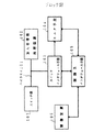
まず、図1はブロック図であり、コネクションレスデータの処理(SMDS)を行う局に設けられる。Hereinafter, embodiments of the present invention will be described in detail with reference to the drawings.
First, FIG. 1 is a block diagram, which is provided in a station that performs connectionless data processing (SMDS).
スイッチインタフェース手段103(スイッチインタフェース部401)は、加入者情報を処理する加入者情報処理装置102(SMDS−MH813)と例えばスイッチ部107(スイッチ部808)とを接続するハイウエイ101(ハイウエイ816)にオプションの外部装置として接続され、そのハイウエイ101から入力されるセルのうち、予め設定されている発信元アドレス又は宛先アドレスに対応するセルを取り込む。 The switch interface unit 103 (switch interface unit 401) is connected to a highway 101 (highway 816) that connects the subscriber information processing apparatus 102 (SMDS-MH813) that processes subscriber information and, for example, the switch unit 107 (switch unit 808). Of the cells connected as an optional external device and inputted from the highway 101, a cell corresponding to a preset source address or destination address is fetched.
モニタ手段104(モニタ部403、データ保持部404)は、予め設定された指示に基づき、スイッチインタフェース手段103から入力されるセルに基づいて、所定の加入者情報のモニタ処理(スペシャルスタディ処理)を実行する。このモニタ処理は、例えば、セル数をカウントする処理、又はイリーガルなセルのロギングを行う処理である。 The monitoring unit 104 (
上述の構成において、モニタ処理の制御を行う制御装置106とインタフェース手段103又はモニタ手段104との間で、制御情報の授受を行う制御系インタフェース手段105(制御系インタフェース部402)を更に有するように構成できる。この制御情報は、例えば、制御装置106からスイッチインタフェース手段103に設定される発信元アドレス又は宛先アドレスDA、制御装置106からモニタ手段104に対して指定されるモニタ指示、又はモニタ手段104から制御装置106に読み出されるモニタ結果である。 In the above-described configuration, the system further includes the control system interface unit 105 (control system interface unit 402) that exchanges control information between the
次に、スペシャルスタディ処理における加入者情報のモニタ技術に関して説明する。
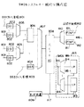
図3は、全体構成図である。
図3において、図8におけるものと同じ番号が付された部分は、図8におけるものと同じ機能を有する。Next, the subscriber information monitoring technique in the special study process will be described.
FIG. 3 is an overall configuration diagram.
In FIG. 3, the same reference numerals as those in FIG. 8 have the same functions as those in FIG.
図3の構成が図8の構成と異なる点は、スイッチ部808とSMDS−MH813とを接続するハイウエイ816に、スペシャルスタディ装置301が、オプションの外部装置として接続される点である。 The configuration in FIG. 3 is different from the configuration in FIG. 8 in that the
SMDS−MH813に収容される加入者情報はハイウエイ816に多重されているため、スペシャルスタディ装置301は、SMDS−MH813と同様にハイウエイ816と接続される。また、スペシャルスタディ装置301は、後述する制御系インタフェース部402(図4)によって、制御装置809と接続される。 Since the subscriber information accommodated in the SMDS-
図3に示されるようにスペシャルスタディ装置301をオプションの外部装置とされる構成により、SMDS−MH813におけるコストの増加を防ぐことができる。
図4は、図3のスペシャルスタディ装置301の構成図である。As shown in FIG. 3, the configuration in which the
FIG. 4 is a configuration diagram of the
まず、スペシャルスタディ装置301は、制御系インタフェース部402及び制御線302により、図3の制御装置809と接続される。制御系インタフェース部402は、DMA(Direct Memory Access)をベースとするPIF(Processor Interface) と呼ばれるインタフェースに基づいて、スイッチインタフェース部401と制御装置809の間、データ保持部404と制御装置809の間、又はモニタ部403と制御装置809の間のデータ転送を制御する。 First, the
今、制御装置809においてスペシャルスタディ処理のためのコマンドが投入されると、そのコマンドの内容に基づいて、スペシャルスタディ処理を行う発信元アドレスSA又は宛先アドレスDAが、制御系インタフェース部402を介してスイッチインタフェース部401にセットされる。 Now, when a command for special study processing is input in the
スイッチインタフェース部401は、ハイウエイ816(図3)に対して、コネクタによって、着脱可能な形式で接続される。そして、このスイッチインタフェース部401は、スイッチ部808(図3)からハイウエイ816を介して入力されるセルのうち、予め制御装置809(図3)から設定されている発信元アドレスSA又は宛先アドレスDAを有するメッセージが格納されているセルのみを取り込み、そのセルをモニタ部403へ入力させる。 The
モニタ部403は、制御系インタフェース部402からのモニタ開始指示に基づいて、スイッチインタフェース部401から入力されるセルに対して、上記モニタ開始指示と共に制御装置809(図3)から設定されたモニタ内容に対応するモニタ処理の実行を開始する。具体的には、例えばモニタ内容が、セル数をカウントするという内容であった場合に、モニタ部403は、セルが受信された旨をデータ保持部404へ通知する。また、例えばモニタ内容が、イリーガルなセルのロギングを行うという内容であった場合に、モニタ部403は、スイッチインタフェース部401から入力されるセルの内容を検査することによって、イリーガルなセルを抽出し、抽出内容をデータ保持部404へ通知する。 Based on the monitor start instruction from the control
データ保持部404は、制御装置809(図3)から設定されたモニタ内容に対応して、次のような動作を行う。即ち、例えばモニタ内容が、セル数をカウントするという内容であった場合に、データ保持部404は、制御系インタフェース部402からのカウント開始指示に基づいてセル数をカウントするためのカウンタ領域をリセットし、モニタ部403から通知がなされる毎にそのカウンタ領域の値をインクリメントし、制御系インタフェース部402からのカウント終了指示に基づいてそのカウンタ領域の値のインクリメント動作を停止する。一方、例えばモニタ内容が、イリーガルなセルのロギングを行うという内容であった場合に、データ保持部404は、モニタ部403から通知された、イリーガルなセルが抽出されたときの抽出内容を、ログとして記録する。上述のカウンタ領域の値又はログの内容は、制御装置809(図3)からのコマンドによって、制御装置809へ読み出される。 The
以上説明したように、図3のスペシャルスタディ装置301がオプションの外部装置としてハイウエイ816に接続されることにより、スペシャルスタディ装置301は、図3の制御装置809から設定された特定の発信元アドレスSA又は宛先アドレスDAに対してのみモニタを行う機能を有すればよい。このため、スペシャルスタディ装置301の構成を単純にすることができる。 As described above, the
これと同時に、スペシャルスタディ装置301をオプションの外部装置としたことにより、SMDS−MH813のコストの増加を抑えることができる。
なお、スペシャルスタディ装置301は、ハイウエイ816上の加入者情報をモニタするだけである。このため、SMDS−MH813が収容できるインタフェース814とラインプロセッサ(LP)815とから構成されるメッセージシェルフ(MESH)の数に影響を与えることはない。At the same time, since the
Note that the
次に、本発明の実施例につき説明する。実施例は、課金処理における加入者情報の収集技術に関するものである。実施例の全体構成は、図8に示されるSMDSの一般的な構成と同様である。 Next, examples of the present invention will be described. The embodiment relates to a technique for collecting subscriber information in billing processing. The overall configuration of the embodiment is the same as the general configuration of SMDS shown in FIG.
まず、実施例の詳細な構成について説明する前に、SMDSにおける課金処理で必要とされる加入者情報である課金パラメータについて説明する。
課金パラメータとしては、宛先アドレスDA、発信元アドレスSA、グループアドレス、キャリア情報、コンディションコード、セグメントカウント、及びパケットカウントがある。そして、以下に説明する実施例では、各宛先局に設置されているSMDS−MH813内のLP815(図8)において、実際に通信が行われた発信元アドレスSAに対応して、宛先アドレスDA、グループアドレス、キャリア情報、コンディションコード、セグメントカウント、及びパケットカウントが記憶される。First, before describing the detailed configuration of the embodiment, a charging parameter, which is subscriber information required for charging processing in SMDS, will be described.
The accounting parameters include destination address DA, source address SA, group address, carrier information, condition code, segment count, and packet count. In the example described below, in the LP 815 (FIG. 8) in the SMDS-
発信元アドレスSAは、各LP815が処理する宛先アドレスDAにメッセージを転送した発信元の加入者のアドレスである。このアドレスは、転送されるメッセージのヘッダ部の発信元アドレスフィールド(SAフィールド)に格納されて転送される。 The source address SA is an address of a source subscriber who has transferred a message to a destination address DA processed by each
宛先アドレスDAは、LP815が処理する宛先の加入者のアドレスである。このアドレスとしては、通常の宛先の加入者アドレスである個別アドレスと、グループアドレスとがある。グループアドレスは、同報通信を実現するために定義されるアドレスである。今、1つのグループアドレスに対して複数の個別アドレスが定義され、そのグループアドレスを宛先アドレスDAとして格納して送信されたメッセージは、ネットワークの機能によって、そのグループアドレスに対して定義されている複数の個別アドレスを有する加入者に同時に送信される。個別アドレス及びグループアドレスは、転送されるメッセージのヘッダ部の宛先アドレスフィールド(DAフィールド)に格納されて転送される。宛先アドレスフィールドに格納されているアドレスが個別アドレスであるかグループアドレスであるかは、そのフィールド内に定義されているフラグによって判別することができる。 The destination address DA is an address of a destination subscriber to be processed by the
キャリア情報は、伝送路の種別を示す情報である。この情報は、例えばLATA間通信と呼ばれる市外通話を提供するネットワークなどにおいて、複数の伝送路業者による複数の種類の伝送路が存在し、それぞれの伝送路毎に課金体系が異なる場合に、参照される。この場合、各局のSMDH MH813(図8)は、メッセージを受信すると、それが局内宛てのメッセージでなければ、そのメッセージに局間用のヘッダを付加した後、そのメッセージを複数のセルを使ってゲートウエイメッセージハンドラに転送する。ゲートウエイメッセージハンドラは、メッセージ内の宛先アドレスDAのうちの上位のエリアコードを判別することにより、そのエリアコードを持つ局を判別して、そのメッセージをその局に転送する。この場合、上述のメッセージは、それが転送される経路の途中に複数の伝送路業者による複数の伝送路が存在する場合は、その伝送路業者の伝送路に転送される。一方、他の伝送路業者の伝送路(図8の局間中継線812)からメッセージを受信したSMDS−MH813は、受信したメッセージの局間用のヘッダ領域に、そのメッセージがどの伝送路業者の伝送路から受信されたかを示すキャリア情報を付加する。このようにして付加されるキャリア情報が、課金処理において参照されるのである。 The carrier information is information indicating the type of transmission path. This information is referred to when there are multiple types of transmission lines by a plurality of transmission line providers in a network that provides a long distance call called inter-LATA communication, and the charging system is different for each transmission line. Is done. In this case, when the SMDH MH 813 (FIG. 8) of each station receives the message, if it is not a message addressed within the station, an inter-station header is added to the message, and then the message is transmitted using a plurality of cells. Forward to gateway message handler. The gateway message handler determines the station having the area code by determining the upper area code of the destination address DA in the message, and transfers the message to the station. In this case, when there are a plurality of transmission paths by a plurality of transmission path providers in the middle of the path to which the message is transferred, the message is transferred to the transmission path of the transmission path provider. On the other hand, the SMDS-
コンディションコードは、セルの伝送エラーの発生の有無、複数のセルを使って伝送されるメッセージの伝送エラーの発生の有無を判別するコードであり、後述する課金処理において検出される。 The condition code is a code for determining whether or not a cell transmission error has occurred and whether or not a transmission error has occurred in a message transmitted using a plurality of cells, and is detected in a billing process described later.
以上の課金パラメータを処理するための課金処理装置の構成を図5に示す。この構成は、各局に設置されているSMDS−MH813内のLP815(図8)に設けられる。
まず、図8のスイッチ部808からハイウエイ816を介して入力されるセル501は、ヘッダ部とペイロード部とによって構成される。図7は、図5の課金処理装置のタイミングチャートである。図7(a) には、ヘッダ部Hとペイロード部Pとからなる3つのセル501の入力タイミングが示されている。FIG. 5 shows the configuration of a charging processing apparatus for processing the above charging parameters. This configuration is provided in LP815 (FIG. 8) in SMDS-MH813 installed in each station.
First, the cell 501 input from the
また、1つのメッセージは、複数のセルを使って転送される。この場合に、メッセージの先頭部分を含むセルはBOM(Bigin Of Message)、メッセージの末尾部分を含むセルはEOM(End Of Message)、メッセージの先頭部分及び末尾部分以外の部分を含むセルはCOM(Continuation Of Message) と呼ばれる。それぞれのセルの属性が、上述のBOM、COM、又はEOMのうちどの属性であるかは、各セルのペイロード部に格納されているセグメントタイプSTによって識別することができる。 One message is transferred using a plurality of cells. In this case, the cell including the head part of the message is BOM (Bigin Of Message), the cell including the tail part of the message is EOM (End Of Message), and the cell including parts other than the head part and the tail part of the message is COM ( Continuation Of Message). Which of the above-described BOM, COM, and EOM the attribute of each cell can be identified by the segment type ST stored in the payload portion of each cell.
課金処理においては、メッセージの内容を判別する必要があるため、上述した各属性を有するセルが、ST識別部502によって識別される。即ち、ST識別部502は、現在入力されているセル501のペイロード部に格納されているセグメントタイプSTを抽出することにより、現在入力されているセル501の属性がBOM、COM、又はEOMのうちどの属性であるかを、後述するSA圧縮部505、セレクタ507、コンディションコード判定部512、及びメッセージ数インクリメント部514に通知する。図7(b) のタイミングチャートの例では、図7(a) に示されるタイミングで入力される3つのセル501のそれぞれに対して、ST識別部502において識別される属性が、BOM、COM、及びEOMであることが示されている。なお、1つのメッセージを格納する複数のセル501は、必ずしも連続して入力される必要はない。 In the charging process, since it is necessary to determine the content of the message, the cell having each attribute described above is identified by the
次に、全体として1つのメッセージを格納する複数のセル501は、同一のVCIを有するように制御されている。VCIは、セル501のヘッダ部に格納されており、例えば図7(c) に示されるタイミングでVCI保持部503に保持される。図7のタイミングチャートでは、全体として1つのメッセージを格納し、それぞれBOM、COM、及びEOMの属性を有する3つのセル501の何れのVCIもαであることが、示されている。 Next, a plurality of cells 501 storing one message as a whole are controlled to have the same VCI. The VCI is stored in the header part of the cell 501, and is held in the
発信元アドレスSAは、複数のセル501のペイロード部P(図7(a) 参照)を使って転送されるメッセージのヘッダ部に格納されており、64ビットのデータである。メッセージのヘッダ部は、BOMの属性を有するセル501に格納されている。これに対して、SA保持部504は、セル501が入力される毎に、そのペイロード部Pのデータの一部を発信元アドレスSAとして保持する。従って、図7(d) に示されるように、BOMの属性を有するセル501が入力されたタイミングにおいてのみ、SA保持部504は、メッセージのヘッダ部に格納されている正しい発信元アドレスSA(=β)を保持することになる。 The source address SA is stored in the header part of the message transferred using the payload part P (see FIG. 7A) of the plurality of cells 501, and is 64-bit data. The header part of the message is stored in a cell 501 having a BOM attribute. On the other hand, each time the cell 501 is input, the
また、SA圧縮部505は、ST識別部502がBOMの属性を有するセル501を検出しているタイミングにおいてのみ、SA保持部504に保持された64ビットの発信元アドレスSAに対して、圧縮処理を実行する。 Also, the
今、図5に示される課金処理装置が設けられるLP815(図8)は、それが含まれる局に収容される最大で32本のDS1加入者線801上の加入者情報を処理することができる。従って、1つのLP815が記憶する発信元アドレスSAの数は、最大で32本のDS1加入者線801に収容される加入者に対応する宛先アドレスDAの何れかに対しメッセージを転送した発信元の加入者の数ということになる。そして、この程度の数の宛先アドレスDAにメッセージを転送する発信元の加入者の数は、210=1024程度でも十分であると推定できる。Now, the LP 815 (FIG. 8) provided with the billing processing apparatus shown in FIG. 5 can process subscriber information on a maximum of 32
そこで、このような推定のもとで、SA圧縮部505は、図6に示される構成によって実現することができる。
図6において、1つのLP815において新規な発信元アドレスSAを有するメッセージが受信される毎に、その発信元アドレスSAが#0〜#n(例えばn=1024)のレジスタ601の何れかに順次保持される。#0〜#nのレジスタ601の出力と、図5のSA保持部504の出力は、#0〜#nの比較器602において比較される。そして、比較結果判定制御部603において一致が検出されたレジスタ601の番号(#0〜#nのうちの何れか)が、圧縮発信元アドレス604として出力される。この結果、64ビットの発信元アドレスSAは、10ビット程度の圧縮発信元アドレス604に圧縮できたことになる。Therefore, based on such estimation, the
In FIG. 6, every time a message having a new source address SA is received by one
図6の構成において実行される具体的な処理は、次の通りである。
まず、図8の制御装置809により実行されるファームウエアは、制御線817を介して、LP815に設けられる図5の課金処理装置のSA圧縮部505内の#0〜#nのレジスタ601の全てに、全てのビットが0であるデータを設定する。また、比較結果判定制御部603は、空きレジスタ番号として0を設定する。Specific processing executed in the configuration of FIG. 6 is as follows.
First, the firmware executed by the
この状態において初めて入力された発信元アドレスSAは、全てのビットが0であるデータではないため、#0〜#nの比較器602の何れにおいてもマッチングがとれないことになる。比較結果判定制御部603は、#0〜#nの比較器602の何れもマッチング出力を出力していないことを判別すると、空きレジスタ番号に対応する#0のレジスタ601に、入力されている発信元アドレスSAを取り込ませる。これと共に、比較結果判定制御部603は、圧縮発信元アドレス604として、レジスタ番号=0を出力する。更に、比較結果判定制御部603は、空きレジスタ番号を0から1にインクリメントする。 Since the source address SA input for the first time in this state is not data in which all the bits are 0, no matching can be obtained in any of the
更に、#0のレジスタ601に保持された発信元アドレスSAと同じアドレスが入力されると、#0〜#nの比較器602の何れにおいてもマッチングがとれないことになる。比較結果判定制御部603は、#0〜#nの比較器602の何れもマッチング出力を出力していないことを再び判別すると、空きレジスタ番号に対応する#1のレジスタ601に、入力されている発信元アドレスSAを取り込ませる。これと共に、比較結果判定制御部603は、圧縮発信元アドレス604として、レジスタ番号=1を出力する。更に、比較結果判定制御部603は、空きレジスタ番号を1から2にインクリメントする。 Furthermore, if the same address as the source address SA held in the # 0
以上のようにして、新たな発信元アドレスSAは、順次レジスタ601に保持されてゆく。
なお、比較結果判定制御部603は、ST識別部502がBOMの属性を有するセル501を検出しているタイミングにおいてのみ、即ち、SA保持部504が正しい発信元アドレスSAを保持しているタイミングにおいてのみ、レジスタ601にその発信元アドレスSAを取り込ませる。As described above, the new source address SA is sequentially held in the
Note that the comparison result
その後、例えば、#0のレジスタ601に保持された発信元アドレスSAと同じアドレスが入力されると、#0の比較器602がマッチング出力を出力する。
この結果、比較結果判定制御部603は、圧縮発信元アドレス604として、レジスタ番号=0を出力する。このようにして、発信元アドレスSAに対する圧縮処理が実現される。Thereafter, for example, when the same address as the source address SA held in the # 0
As a result, the comparison result
なお、#0〜#nの全てのレジスタ601が使い切られてしまった場合には、制御装置809内のメモリがレジスタ601の代りに使用されるように構成されてもよい。このような構成の場合、レジスタ601に保持されている発信元アドレスSAが、その通信頻度に応じて、制御装置809内のメモリに保持される発信元アドレスSAと入れ替えられるように構成されてもよい。 If all the
次に、図5のSA圧縮部505から図7(e) に示されるタイミングで出力される圧縮発信元アドレス604(=β′)は、図7(f) に示されるタイミングで、VCI−圧縮SA対応RAM506(Din)に書き込まれる。この場合のアドレス(A)としては、圧縮発信元アドレス604に対応する発信元アドレスSAが格納されていたセル501のVCIであって、VCI保持部503で保持されているVCIが使用される。この結果、VCI−圧縮SA対応RAM506の出力(Dout )は、図7(g) に示される如くとなる。 Next, the compressed source address 604 (= β ′) output from the
即ち、VCI−圧縮SA対応RAM506は、BOMの属性を有するセル501が入力されるタイミングにおいてのみ、そのセル501のペイロード部に格納されているメッセージの発信元アドレスSAに対応する圧縮発信元アドレス604を、そのセル501のVCIに対応するアドレスに書き込み、それ以外のタイミングにおいては、現在入力しているセル501のVCIに対応するアドレスから、そのVCIに対応する圧縮発信元アドレス604を出力することになる。 In other words, the VCI-compressed SA correspondence RAM 506 is the compressed source address 604 corresponding to the source address SA of the message stored in the payload portion of the cell 501 only at the timing when the cell 501 having the BOM attribute is input. To the address corresponding to the VCI of the cell 501, and at other timings, the compressed source address 604 corresponding to the VCI is output from the address corresponding to the VCI of the cell 501 currently input. become.
VCI−圧縮SA対応RAM506の出力とSA圧縮部505の出力は、それぞれセレクタ507に入力している。セレクタ507は、図7(h) 及び(i) に示されるように、ST識別部502がBOMの属性を有するセル501を検出しているタイミングでは、SA圧縮部505の出力を通過させ、ST識別部502がBOM以外の属性を有するセル501を検出しているタイミングでは、VCI−圧縮SA対応RAM506の出力を通過させる。セレクタ507から出力される圧縮発信元アドレスは、課金パラメータ蓄積用2ポートRAM515に、アドレス(A)として入力される。 The output of the VCI-compressed SA compatible RAM 506 and the output of the
この結果、課金パラメータ蓄積用2ポートRAM515は、この圧縮発信元アドレス毎に、後述するその他の課金パラメータを蓄積することになる。この場合に、圧縮発信元アドレスのビット数は、前述したように10ビット程度である。このため、課金パラメータ蓄積用2ポートRAM515は、通常のLSIチップによって構築可能である。また、BOMの属性を有するセル501の入力タイミング以外でも、VCI−圧縮SA対応RAM506が、現在入力しているセル501のVCIに対応する正しい圧縮発信元アドレスを出力する。このため、課金パラメータ蓄積用2ポートRAM515は、常に、現在入力しているセル501のVCIに対応する正しい圧縮発信元アドレスに対応する課金パラメータを収集することができる。 As a result, the charging parameter storage 2-port RAM 515 stores other charging parameters to be described later for each compressed transmission source address. In this case, the number of bits of the compressed source address is about 10 bits as described above. For this reason, the charging parameter storage 2-port RAM 515 can be constructed by a normal LSI chip. In addition to the input timing of the cell 501 having the BOM attribute, the VCI-compressed SA compatible RAM 506 outputs a correct compressed source address corresponding to the VCI of the cell 501 currently input. For this reason, the charging parameter storage 2-port RAM 515 can always collect charging parameters corresponding to the correct compressed source address corresponding to the VCI of the cell 501 currently input.
次に、キャリア情報及び宛先アドレスDAは、発信元アドレスSAと同様、複数のセル501のペイロード部P(図7(a) 参照)を使って転送されるメッセージのヘッダ部に格納されている。メッセージのヘッダ部は、BOMの属性を有するセル501に格納されている。これに対し、キャリア情報保持部508及びDA保持部510は、それぞれ、SA保持部504と同様、セル501が入力される毎に、そのペイロード部Pのデータの一部をキャリア情報及び宛先アドレスDAとして保持する。従って、図7(l) 及び(j) に示されるように、BOMの属性を有するセル501が入力されたタイミングにおいてのみ、キャリア情報保持部508及びDA保持部510は、メッセージのヘッダ部に格納されている正しいキャリア情報(=δ)及び宛先アドレスDA(=γ)を保持することになる。 Next, the carrier information and the destination address DA are stored in the header portion of the message transferred using the payload portions P (see FIG. 7A) of the plurality of cells 501 as with the source address SA. The header part of the message is stored in a cell 501 having a BOM attribute. On the other hand, each of the carrier
また、キャリア情報圧縮部509及びDA圧縮部511は、それぞれ、キャリア情報保持部508及びDA保持部510が保持したキャリア情報及び宛先アドレスDAに対して、圧縮処理を実行する。これらの部分の構成は、SA圧縮部505に対応する図6の構成と同様である。 In addition, the carrier
今、宛先アドレスDAは、64ビットのデータ量を有する。ここで、前述のように、1つのLP815は、それが含まれる局が収容する最大で32本のDS1加入者線801上の加入者情報を扱うことができる。そして、1本のDS1加入者線801上では、宛先アドレスDAとして、最大で16種の個別アドレスと、最大で48種のグループアドレス(後述する)からなる、最大で64種のアドレスが定義可能である。従って、1つのLP815が扱う宛先アドレスDAの最大数は、64×32=2048である。従って、図6の#0〜#n=#2048のレジスタ601に、予めLP815が処理する宛先アドレスDAのパターンを登録しておくことにより、64ビットの宛先アドレスDAを、11ビット程度の圧縮宛先アドレスに変換することができる。 Now, the destination address DA has a data amount of 64 bits. Here, as described above, one
一方、キャリア情報の種類は元々多くはないため、その種類に応じた数のレジスタ601に、予めキャリア情報のパターンを登録しておくことにより、キャリア情報の圧縮が可能となる。 On the other hand, since there are not so many types of carrier information, carrier information can be compressed by previously registering carrier information patterns in the number of
なお、キャリア情報圧縮部509又はDA圧縮部511を実現する図6の構成においては、レジスタ601に予めパターンを登録しておけばよいため、比較結果判定制御部603がレジスタ601にデータを自律的に取り込ませる機能は不要で、また、ST識別部502からの制御情報も不要である。 In the configuration of FIG. 6 that realizes the carrier
以上のようにしてキャリア情報圧縮部509及びDA圧縮部511から、それぞれ図7(m) 及び(k) に示されるタイミングで出力される圧縮キャリア情報(=δ′)及び圧縮宛先アドレス(=γ′)は、課金パラメータ蓄積用2ポートRAM515の第1のメモリチップに書き込まれる。この場合のアドレス(A)は、前述したように、セレクタ507から出力される現在入力しているセル501のVCIに対応する圧縮発信元アドレス(=β′(図7(i) ))である。また、上述した書込みが行われるタイミングは、図7(r) に示されるタイミングのうち、BOMの属性を有するセル501が入力されるタイミングのみである。 As described above, the compressed carrier information (= δ ′) and the compressed destination address (= γ) output from the carrier
コンディションコード判定部512は、セル501の伝送エラーの発生の有無と、複数のセル501を使って伝送されるメッセージの伝送エラーの発生の有無を判別する。この判別は、例えばセル501に付加されている検査ビット及びメッセージに付加されている検査ビットを検査することにより行われる。セル数インクリメント部513は、セル501が到着する毎に、セル501の数をカウントする。メッセージ数インクリメント部514は、複数のセル501を使って伝送されるメッセージが到着する毎に、メッセージの数をカウントする。 The condition
そして、コンディションコード判定部512から出力されるコンディションコード、セル数インクリメント部513から出力されるセル数、及びメッセージ数インクリメント部514から出力されるメッセージ数は、図7(r) に示される各タイミングで、課金パラメータ蓄積用2ポートRAM515の第2のメモリチップに書き込まれる。この場合のアドレス(A)は、セレクタ507から出力される現在入力しているセル501のVCIに対応する圧縮発信元アドレス(=β′(図7(i) ))である。 The condition code output from the condition
この場合に、コンディションコード判定部512は、1つのメッセージ全体について、そのメッセージが格納される複数のセル501のそれぞれの入力タイミング毎に、セル501の伝送エラーの発生の有無と、複数のセル501を使って伝送されるメッセージの伝送エラーの発生の有無を判別する必要がある。このため、コンディションコード判定部512は、メッセージの入力開始以降から現在までのコンディションコードを必要とする。そこで、コンディションコード判定部512は、図7(o) に示される各タイミングで、課金パラメータ蓄積用2ポートRAM515の第2のメモリチップから、過去のコンディションコードを読み出し、そのコンディションコードを今回の判定処理に使用する。この場合のアドレス(A)は、セレクタ507から出力される現在入力しているセル501のVCIに対応する圧縮発信元アドレス(=β′(図7(i) ))である。この結果、コンディションコード判定部512は、セル501の入力タイミングに同期し、図7(n) に示されるようにコンディションコードを順次出力することになる。 In this case, the condition
また、セル数インクリメント部513は、セル数を順次インクリメントするために、現在までのセル数を必要とする。そこで、セル数インクリメント部513は、図7(o) に示される各タイミングで、課金パラメータ蓄積用2ポートRAM515の第2のメモリチップから、現在までのセル数を読み出し、そのセル数に対してインクリメント処理を実行する。この場合のアドレス(A)は、セレクタ507から出力される現在入力しているセル501のVCIに対応する圧縮発信元アドレス(=β′(図7(i) ))である。この結果、セル数インクリメント部513は、セル501の入力タイミングに同期して、図7(p) に示されるようにセル数を順次出力することになる。 Further, the cell
更に、メッセージ数インクリメント部514は、メッセージ数を順次インクリメントするために、現在までのメッセージ数を必要とする。そこで、メッセージ数インクリメント部514は、図7(o) に示されるタイミングのうちEOFの属性を有するセル501が入力されるタイミングにおいてのみ、課金パラメータ蓄積用2ポートRAM515の第2のメモリチップから、現在までのメッセージ数を読み出し、そのメッセージ数に対してインクリメント処理を実行する。この場合のアドレス(A)は、セレクタ507から出力される現在入力しているセル501のVCIに対応する圧縮発信元アドレス(=β′(図7(i) ))である。この結果、メッセージ数インクリメント部514は、メッセージの終了を示すEOFの属性を有するセル501が入力されるタイミングに同期して、図7(q) に示されるようにセル数を出力することになる。なお、図7(q) において斜線部で示されるタイミングは、メッセージ数のインクリメント処理が行われないタイミングである。 Further, the message
なお、上述した課金パラメータ蓄積用2ポートRAM515の第1のメモリチップ及び第2のメモリチップの各アドレスには、制御装置809のファームウエアによって、予めオール0が設定されている。 Note that all 0s are set in advance by the firmware of the
以上説明したようにして、課金パラメータ蓄積用2ポートRAM515の第1及び第2のメモリチップに、圧縮発信元アドレスに対応するアドレス毎に、圧縮キャリア情報、圧縮宛先アドレス、コンディションコード、セル数、及びメッセージ数が蓄積されることになる。 As described above, in the first and second memory chips of the charging parameter storage 2-port RAM 515, for each address corresponding to the compressed source address, the compressed carrier information, the compressed destination address, the condition code, the number of cells, And the number of messages is accumulated.
これに対して、制御装置809(図8)が実行するファームウエアは、LP815に接続される制御線817を介して、定期的に、課金パラメータ蓄積用2ポートRAM515から、各圧縮発信元アドレス毎に課金パラメータを読み出し、課金データを組み立てる。 On the other hand, the firmware executed by the control device 809 (FIG. 8) is periodically sent from the charging parameter accumulation 2-port RAM 515 via the
具体的には、ファームウエアは、まず、SA圧縮部505(図5)内の#0のレジスタ601(図6)に自律的に保持されている発信元アドレスSAを読み出す。次に、ファームウエアは、課金パラメータ蓄積用2ポートRAM515の第1のメモリチップにおいて、圧縮発信元アドレス=0(#0のレジスタ601に対応する)から、圧縮キャリア情報及び圧縮宛先アドレスを読み出す。そして、ファームウエアは、その圧縮キャリア情報に対応する番号のキャリア情報圧縮部509(図5)内のレジスタ601(図6)から、その圧縮キャリア情報に対応するキャリア情報を読み出す。また、ファームウエアは、その圧縮宛先アドレスに対応する番号のDA圧縮部511(図5)内のレジスタ601(図6)から、その圧縮宛先アドレスに対応する宛先アドレスDAを読み出す。続いて、ファームウエアは、課金パラメータ蓄積用2ポートRAM515の第2のメモリチップにおいて、圧縮発信元アドレス=0(#0のレジスタ601に対応する)から、コンディションコード、セル数、及びメッセージ数を読み出す。 Specifically, the firmware first reads the source address SA autonomously held in the # 0 register 601 (FIG. 6) in the SA compression unit 505 (FIG. 5). Next, the firmware reads the compressed carrier information and the compressed destination address from the compressed transmission source address = 0 (corresponding to the
このようにして、ファームウエアは、1つの発信元アドレスSAに対応するキャリア情報、宛先アドレスDA、コンディションコード、セル数、及びメッセージ数を、課金データとして抽出することができる。 In this way, the firmware can extract the carrier information, destination address DA, condition code, number of cells, and number of messages corresponding to one source address SA as billing data.
ファームウエアは、SA圧縮部505(図5)内の#1以降のレジスタ601(図6)の内容についても、発信元アドレスSAが保持されている場合には、上述の場合と同様の課金データの抽出処理を実行する。そして、レジスタ601の内容が0である場合は、そのレジスタ601の番号以降の番号のレジスタ601には発信元アドレスSAは自律的に登録されていないため、ファームウエアは、課金データの抽出処理を終了する。 The firmware stores the same billing data as in the above-described case when the source address SA is held for the contents of the register 601 (FIG. 6) after # 1 in the SA compression unit 505 (FIG. 5). Execute the extraction process. If the content of the
以上説明した実施例において、図5の課金処理装置に入力されるセル501は、予めスクリーニングによって受け入れられたもののみが入力されるように構成することができる。スクリーニングとは、LP815が、それが処理する宛先アドレスDA毎に、それが受信したその宛先アドレスDA宛てのメッセージのうち、予め定義された特定の発信元アドレスSAを有するメッセージのみを受け入れ或いは受け入れない制御を行う機能をいう。この機能を実現するため、LP815は、スクリーニング用のテーブルを内蔵している。そして、LP815は、それが受信したメッセージに格納されている発信元アドレスSAが、そのメッセージに格納されている宛先アドレスDAに対応するテーブルに登録されている発信元アドレスSAに含まれている場合には、そのメッセージを受け入れ、或いは受け入れない制御を行う。この場合に、加入者は、加入時に、LP815に対して受入れ制御と受入れ拒否制御のどちらを実行させるかを選択することができる。 In the embodiment described above, the cell 501 input to the billing processing apparatus of FIG. 5 can be configured such that only those previously accepted by screening are input. Screening means that for each destination address DA that it processes, the
このようにして、スクリーニングによって受け入れられたセル501のみが課金処理装置に入力されることにより、加入者に転送されるメッセージを、加入者の選択に基づいて制限することができる。 In this way, only the cells 501 accepted by the screening are input to the billing processing apparatus, so that the messages transferred to the subscriber can be restricted based on the subscriber's selection.
上述した実施例では、図5のSA圧縮部505内で発信元アドレスSAを保持するレジスタ601の数(n)は1024程度であったが、本発明はこれに限られることはない。レジスタ601の数が例えば216程度に増加したとしても、図5に示した課金処理装置は、通常の回路素子によって十分に構築可能である。In the embodiment described above, the number (n) of the
また、SA圧縮部505、キャリア情報圧縮部509、及びDA圧縮部511は、図6に示されるように複数のレジスタ601を中心に構成されているが、複数のレジスタ601の代りにメモリを使用して構成されてもよい。 Further, the
更に、課金パラメータ蓄積用2ポートRAM515は、必ずしも2つのメモリチップによって構成しなければならないという必然性もない。 Further, the charging parameter storage 2-port RAM 515 is not necessarily configured by two memory chips.
101 ハイウエイ
102 加入者情報処理装置
103 スイッチインタフェース手段
104 モニタ手段
105 制御系インタフェース手段
106 制御装置
107 スイッチ部
201 セル
202 発信元アドレス抽出手段
203 発信元アドレス
204 発信元アドレス圧縮手段
205 圧縮発信元アドレス
206 課金情報抽出手段
207 課金情報
208 課金情報蓄積手段
209 課金情報圧縮手段
210 圧縮課金情報
211 圧縮発信元アドレス記憶手段
212 仮想識別子
213 圧縮発信元アドレス
301 スペシャルスタディ装置
302 制御線
401 スイッチインタフェース部
402 制御系インタフェース部
403 モニタ部
404 データ保持部
501 セル
502 ST識別部
503 VCI保持部
504 SA保持部
505 SA圧縮部
506 VCI−圧縮SA対応RAM
507 セレクタ
508 キャリア情報保持部
509 キャリア情報圧縮部
510 DA保持部
511 DA圧縮部
512 コンディションコード判定部
513 セル数インクリメント部
514 メッセージ数インクリメント部
515 課金パラメータ蓄積用2ポートRAM
601 レジスタ
602 比較器
603 比較結果判定制御部
604 圧縮発信元アドレス604
801 DS1加入者線
802 DS1終端部
803 DS3加入者線
804 DS3終端部
805、806、807、810 マルチプレクサ/デマルチプレクサ
808 スイッチ部
809 制御装置
811 終端回路(FINF)
812 局間中継線
813 SMDSメッセージハンドラ(SMDS−MH)
814 インタフェース
815 LP
816 ハイウエイ
817 制御線DESCRIPTION OF SYMBOLS 101 Highway 102 Subscriber information processing apparatus 103 Switch interface means 104 Monitor means 105 Control system interface means 106
507
801
812
814
816
Claims (10)
該局が収容する加入者を宛先として受信されたセルから、発信元アドレスを抽出する発信元アドレス抽出手段と、
該発信元アドレス抽出手段が抽出した発信元アドレスを圧縮し、圧縮発信元アドレスを出力する発信元アドレス圧縮手段と、
前記受信されたセルから、所定の加入者情報を課金情報として抽出する課金情報抽出手段と、
前記発信元アドレス圧縮手段が出力する圧縮発信元アドレスに対応するアドレスに、前記課金情報抽出手段が抽出する課金情報を蓄積する課金情報蓄積手段と、
を有することを特徴とするコネクションレスデータサービスにおける加入者情報の処理方式。 It is provided in a station that processes connectionless data,
A source address extracting means for extracting a source address from a cell received with a subscriber accommodated by the station as a destination;
A source address compressing unit that compresses the source address extracted by the source address extracting unit and outputs a compressed source address;
Charging information extracting means for extracting predetermined subscriber information as charging information from the received cell;
Charging information storage means for storing charging information extracted by the charging information extraction means at an address corresponding to the compressed transmission source address output by the transmission source address compression means;
A method for processing subscriber information in a connectionless data service.
該局が収容する加入者を宛先として受信されたセルから、発信元アドレスを抽出する発信元アドレス抽出手段と、
該発信元アドレス抽出手段が抽出した発信元アドレスを圧縮し、圧縮発信元アドレスを出力する発信元アドレス圧縮手段と、
前記受信されたセルから、所定の加入者情報を課金情報として抽出する課金情報抽出手段と、
該課金情報抽出手段が抽出する課金情報を圧縮し、圧縮課金情報を出力する課金情報圧縮手段と、
前記発信元アドレス圧縮手段が出力する圧縮発信元アドレスに対応するアドレスに、前記課金情報圧縮手段が出力する圧縮課金情報を蓄積する課金情報蓄積手段と、
を有することを特徴とするコネクションレスデータサービスにおける加入者情報の処理方式。 It is provided in a station that processes connectionless data,
A source address extracting means for extracting a source address from a cell received with a subscriber accommodated by the station as a destination;
A source address compressing unit that compresses the source address extracted by the source address extracting unit and outputs a compressed source address;
Charging information extracting means for extracting predetermined subscriber information as charging information from the received cell;
Charging information compression means for compressing the charging information extracted by the charging information extraction means and outputting the compressed charging information;
Charging information storage means for storing the compressed charging information output by the charging information compression means at an address corresponding to the compressed transmission source address output by the transmission source address compression means;
A method for processing subscriber information in a connectionless data service.
該局が収容する加入者を宛先として受信されたセルから、発信元アドレスを抽出する発信元アドレス抽出手段と、
該発信元アドレス抽出手段が抽出した発信元アドレスを圧縮し、圧縮発信元アドレスを出力する発信元アドレス圧縮手段と、
前記受信されたセルの仮想識別子に対応するアドレスに、前記発信元アドレス圧縮手段が出力する有効な圧縮発信元アドレスを記憶する圧縮発信元アドレス記憶手段と、
前記受信されたセルから、所定の加入者情報を課金情報として抽出する課金情報抽出手段と、
前記発信元アドレス圧縮手段が有効な圧縮発信元アドレスを出力している場合には、該発信元アドレス圧縮手段が出力する圧縮発信元アドレスに対応するアドレスに、前記課金情報抽出手段が抽出する課金情報を蓄積し、前記発信元アドレス圧縮手段が有効な圧縮発信元アドレスを出力していない場合には、前記圧縮発信元アドレス記憶手段の前記受信されたセルの仮想識別子に対応するアドレスから読み出される圧縮発信元アドレスに対応するアドレスに、前記課金情報抽出手段が抽出する課金情報を蓄積する課金情報蓄積手段と、
を有することを特徴とするコネクションレスデータサービスにおける加入者情報の処理方式。 It is provided in a station that processes connectionless data,
A source address extracting means for extracting a source address from a cell received with a subscriber accommodated by the station as a destination;
A source address compressing unit that compresses the source address extracted by the source address extracting unit and outputs a compressed source address;
Compressed source address storage means for storing an effective compressed source address output by the source address compression means at an address corresponding to the virtual identifier of the received cell;
Charging information extracting means for extracting predetermined subscriber information as charging information from the received cell;
When the source address compressing means outputs a valid compressed source address, the accounting information extracting means extracts the billing information extracted by the address corresponding to the compressed source address output by the source address compressing means. When the information is stored and the source address compression means does not output a valid compressed source address, the information is read from the address corresponding to the virtual identifier of the received cell in the compressed source address storage means Charging information storage means for storing charging information extracted by the charging information extraction means at an address corresponding to a compressed source address;
A method for processing subscriber information in a connectionless data service.
該局が収容する加入者を宛先として受信されたセルから、発信元アドレスを抽出する発信元アドレス抽出手段と、
該発信元アドレス抽出手段が抽出した発信元アドレスを圧縮し、圧縮発信元アドレスを出力する発信元アドレス圧縮手段と、
前記受信されたセルの仮想識別子に対応するアドレスに、前記発信元アドレス圧縮手段が出力する圧縮発信元アドレスを記憶する圧縮発信元アドレス記憶手段と、
前記受信されたセルから、所定の加入者情報を課金情報として抽出する課金情報抽出手段と、
該課金情報抽出手段が抽出する課金情報を圧縮し、圧縮課金情報を出力する課金情報圧縮手段と、
前記発信元アドレス圧縮手段が有効な圧縮発信元アドレスを出力している場合には、該発信元アドレス圧縮手段が出力する圧縮発信元アドレスに対応するアドレスに、前記課金情報圧縮手段が出力する圧縮課金情報を蓄積し、前記発信元アドレス圧縮手段が有効な圧縮発信元アドレスを出力していない場合には、前記圧縮発信元アドレス記憶手段の前記受信されたセルの仮想識別子に対応するアドレスから読み出される圧縮発信元アドレスに対応するアドレスに、前記課金情報圧縮手段が出力する圧縮課金情報を蓄積する課金情報蓄積手段と、
を有することを特徴とするコネクションレスデータサービスにおける加入者情報の処理方式。 It is provided in a station that processes connectionless data,
A source address extracting means for extracting a source address from a cell received with a subscriber accommodated by the station as a destination;
A source address compressing unit that compresses the source address extracted by the source address extracting unit and outputs a compressed source address;
Compressed source address storage means for storing the compressed source address output by the source address compression means at an address corresponding to the virtual identifier of the received cell;
Charging information extracting means for extracting predetermined subscriber information as charging information from the received cell;
Charging information compression means for compressing the charging information extracted by the charging information extraction means and outputting the compressed charging information;
When the source address compressing means outputs a valid compressed source address, the compression that the accounting information compressing means outputs to the address corresponding to the compressed source address output by the source address compressing means When charging information is stored and the source address compression means does not output a valid compressed source address, it is read from the address corresponding to the virtual identifier of the received cell of the compressed source address storage means. Charging information storage means for storing the compressed charging information output by the charging information compression means at an address corresponding to the compressed transmission source address;
A method for processing subscriber information in a connectionless data service.
所定数の発信元アドレス記憶手段と、 前記発信元アドレス抽出手段が抽出した発信元アドレスと、前記各発信元アドレス記憶手段に記憶されている発信元アドレスのそれぞれとが一致するか否かを比較する発信元アドレス比較手段と、
該発信元アドレス比較手段において一致が検出された場合に、該一致が検出された発信元アドレス記憶手段の識別情報を前記圧縮発信元アドレスとして出力し、前記発信元アドレス比較手段において一致が検出されなかった場合に、前記発信元アドレスが記憶されていない発信元アドレス記憶手段に前記発信元アドレス抽出手段が抽出した発信元アドレスを書き込むと共に、該書込みを行った発信元アドレス記憶手段の識別情報を前記圧縮発信元アドレスとして出力する比較結果判定制御手段と、
を有することを特徴とする請求項1乃至4の何れか1項に記載のコネクションレスデータサービスにおける加入者情報の処理方式。 The source address compression means includes:
A comparison is made between a predetermined number of source address storage means, a source address extracted by the source address extraction means, and a source address stored in each source address storage means. A source address comparison means to
When a match is detected in the source address comparison means, the identification information of the source address storage means in which the match is detected is output as the compressed source address, and a match is detected in the source address comparison means If there is not, the source address extracted by the source address extracting means is written in the source address storage means in which the source address is not stored, and the identification information of the source address storage means that performed the writing is written Comparison result determination control means for outputting as the compressed source address;
The subscriber information processing method in the connectionless data service according to any one of claims 1 to 4, characterized by comprising:
ことを特徴とする請求項1乃至5の何れか1項に記載のコネクションレスデータサービスにおける加入者情報の処理方式。 The billing information includes a destination address;
6. A method for processing subscriber information in a connectionless data service according to any one of claims 1 to 5.
ことを特徴とする請求項1乃至5の何れか1項に記載のコネクションレスデー
タサービスにおける加入者情報の処理方式。 The billing information includes carrier information,
6. A method for processing subscriber information in a connectionless data service according to any one of claims 1 to 5.
ことを特徴とする請求項1乃至5の何れか1項に記載のコネクションレスデータサービスにおける加入者情報の処理方式。 The billing information includes a condition code,
6. A method for processing subscriber information in a connectionless data service according to any one of claims 1 to 5.
ことを特徴とする請求項1乃至5の何れか1項に記載のコネクションレスデータサービスにおける加入者情報の処理方式。 The charging information includes information on the number of cells,
6. A method for processing subscriber information in a connectionless data service according to any one of claims 1 to 5.
ことを特徴とする請求項1乃至5の何れか1項に記載のコネクションレスデータサービスにおける加入者情報の処理方式。 The billing information includes information about the number of messages,
6. A method for processing subscriber information in a connectionless data service according to any one of claims 1 to 5.
Priority Applications (1)
| Application Number | Priority Date | Filing Date | Title |
|---|---|---|---|
| JP2004169182A JP3663205B2 (en) | 2004-06-07 | 2004-06-07 | Processing method of subscriber information in connectionless data service |
Applications Claiming Priority (1)
| Application Number | Priority Date | Filing Date | Title |
|---|---|---|---|
| JP2004169182A JP3663205B2 (en) | 2004-06-07 | 2004-06-07 | Processing method of subscriber information in connectionless data service |
Related Parent Applications (1)
| Application Number | Title | Priority Date | Filing Date |
|---|---|---|---|
| JP5233461A Division JPH0795230A (en) | 1993-09-20 | 1993-09-20 | Processing system for subscriber's information in connectionless data service |
Publications (2)
| Publication Number | Publication Date |
|---|---|
| JP2004266867A JP2004266867A (en) | 2004-09-24 |
| JP3663205B2 true JP3663205B2 (en) | 2005-06-22 |
Family
ID=33128743
Family Applications (1)
| Application Number | Title | Priority Date | Filing Date |
|---|---|---|---|
| JP2004169182A Expired - Fee Related JP3663205B2 (en) | 2004-06-07 | 2004-06-07 | Processing method of subscriber information in connectionless data service |
Country Status (1)
| Country | Link |
|---|---|
| JP (1) | JP3663205B2 (en) |
-
2004
- 2004-06-07 JP JP2004169182A patent/JP3663205B2/en not_active Expired - Fee Related
Also Published As
| Publication number | Publication date |
|---|---|
| JP2004266867A (en) | 2004-09-24 |
Similar Documents
| Publication | Publication Date | Title |
|---|---|---|
| US6907001B1 (en) | Packet switch for switching variable length packets in the form of ATM cells | |
| US5485453A (en) | Method for handling redundant switching planes in packet switches and a packet switch for carrying out the method | |
| US8767565B2 (en) | Flexible network test apparatus | |
| US5761191A (en) | Statistics collection for ATM networks | |
| JPH05336159A (en) | Cell multiplex system for plural sets of information | |
| US5790525A (en) | Information collection device and method for use with communications networks | |
| US5974458A (en) | Data transfer accounting device and method for performing an accounting process including an accounting information collecting process | |
| US5561662A (en) | Subscriber information processing method in a connectionless data service | |
| EP0687121B1 (en) | Device and method for indicating timeouts | |
| US6175567B1 (en) | Method and system for multiplexing/demultiplexing asynchronous transfer mode interprocessor communication (ATM IPC) cell in exchange | |
| US6747954B1 (en) | Asynchronous transfer mode switch providing pollstate status information | |
| JP3663205B2 (en) | Processing method of subscriber information in connectionless data service | |
| US7450594B2 (en) | Message writing apparatus, message writing method, message readout apparatus, message readout method, memory address control circuit for writing of variable-length message and memory address control circuit for readout of variable-length message | |
| EP0861534B1 (en) | Instrument for test and measurement of atm network virtual connections | |
| US6005844A (en) | Information collection device and method for use with communications networks | |
| JP4562969B2 (en) | Client terminal telecommunications equipment | |
| JP3256567B2 (en) | Connectionless message billing system in ATM network | |
| US5787075A (en) | Switched multi-megabit digital service switching apparatus | |
| JP3584853B2 (en) | Packet switch, packet switching method | |
| US20020141411A1 (en) | Apparatus for line-concentrating and distributing PPP frame data | |
| KR100483546B1 (en) | Apparatus and method of multicast switching by ATM cell copying | |
| JP3100612B2 (en) | Billing method and apparatus in exchange | |
| JPH05130131A (en) | Connection less communication system in atm | |
| JP3385108B2 (en) | Cell billing device | |
| KR100259047B1 (en) | Cell Counting Methods on Connectionless Servers |
Legal Events
| Date | Code | Title | Description |
|---|---|---|---|
| A621 | Written request for application examination |
Free format text: JAPANESE INTERMEDIATE CODE: A621 Effective date: 20040628 |
|
| A521 | Written amendment |
Free format text: JAPANESE INTERMEDIATE CODE: A523 Effective date: 20040628 |
|
| A977 | Report on retrieval |
Free format text: JAPANESE INTERMEDIATE CODE: A971007 Effective date: 20050308 |
|
| TRDD | Decision of grant or rejection written | ||
| A01 | Written decision to grant a patent or to grant a registration (utility model) |
Free format text: JAPANESE INTERMEDIATE CODE: A01 Effective date: 20050315 |
|
| A61 | First payment of annual fees (during grant procedure) |
Free format text: JAPANESE INTERMEDIATE CODE: A61 Effective date: 20050325 |
|
| R150 | Certificate of patent or registration of utility model |
Free format text: JAPANESE INTERMEDIATE CODE: R150 |
|
| FPAY | Renewal fee payment (event date is renewal date of database) |
Free format text: PAYMENT UNTIL: 20080401 Year of fee payment: 3 |
|
| FPAY | Renewal fee payment (event date is renewal date of database) |
Free format text: PAYMENT UNTIL: 20090401 Year of fee payment: 4 |
|
| LAPS | Cancellation because of no payment of annual fees |