JP3661594B2 - Data stream generating apparatus and method, variable length encoded data stream generating apparatus and method, and camera system - Google Patents
Data stream generating apparatus and method, variable length encoded data stream generating apparatus and method, and camera system Download PDFInfo
- Publication number
- JP3661594B2 JP3661594B2 JP2001031485A JP2001031485A JP3661594B2 JP 3661594 B2 JP3661594 B2 JP 3661594B2 JP 2001031485 A JP2001031485 A JP 2001031485A JP 2001031485 A JP2001031485 A JP 2001031485A JP 3661594 B2 JP3661594 B2 JP 3661594B2
- Authority
- JP
- Japan
- Prior art keywords
- data
- length
- output
- predetermined
- data length
- Prior art date
- Legal status (The legal status is an assumption and is not a legal conclusion. Google has not performed a legal analysis and makes no representation as to the accuracy of the status listed.)
- Expired - Fee Related
Links
Images


Classifications
-
- H—ELECTRICITY
- H04—ELECTRIC COMMUNICATION TECHNIQUE
- H04N—PICTORIAL COMMUNICATION, e.g. TELEVISION
- H04N19/00—Methods or arrangements for coding, decoding, compressing or decompressing digital video signals
- H04N19/90—Methods or arrangements for coding, decoding, compressing or decompressing digital video signals using coding techniques not provided for in groups H04N19/10-H04N19/85, e.g. fractals
- H04N19/93—Run-length coding
-
- H—ELECTRICITY
- H04—ELECTRIC COMMUNICATION TECHNIQUE
- H04N—PICTORIAL COMMUNICATION, e.g. TELEVISION
- H04N1/00—Scanning, transmission or reproduction of documents or the like, e.g. facsimile transmission; Details thereof
- H04N1/32—Circuits or arrangements for control or supervision between transmitter and receiver or between image input and image output device, e.g. between a still-image camera and its memory or between a still-image camera and a printer device
- H04N1/32609—Fault detection or counter-measures, e.g. original mis-positioned, shortage of paper
- H04N1/32614—Fault detection or counter-measures, e.g. original mis-positioned, shortage of paper related to a single-mode communication, e.g. at the transmitter or at the receiver
-
- H—ELECTRICITY
- H04—ELECTRIC COMMUNICATION TECHNIQUE
- H04N—PICTORIAL COMMUNICATION, e.g. TELEVISION
- H04N1/00—Scanning, transmission or reproduction of documents or the like, e.g. facsimile transmission; Details thereof
- H04N1/32—Circuits or arrangements for control or supervision between transmitter and receiver or between image input and image output device, e.g. between a still-image camera and its memory or between a still-image camera and a printer device
- H04N1/32609—Fault detection or counter-measures, e.g. original mis-positioned, shortage of paper
- H04N1/32625—Fault detection
- H04N1/32641—Fault detection of transmission or transmitted data, e.g. interruption or wrong number of pages
-
- H—ELECTRICITY
- H04—ELECTRIC COMMUNICATION TECHNIQUE
- H04N—PICTORIAL COMMUNICATION, e.g. TELEVISION
- H04N1/00—Scanning, transmission or reproduction of documents or the like, e.g. facsimile transmission; Details thereof
- H04N1/32—Circuits or arrangements for control or supervision between transmitter and receiver or between image input and image output device, e.g. between a still-image camera and its memory or between a still-image camera and a printer device
- H04N1/32609—Fault detection or counter-measures, e.g. original mis-positioned, shortage of paper
- H04N1/32646—Counter-measures
- H04N1/32683—Preventive counter-measures, e.g. using redundant hardware, or anticipating a fault
-
- H—ELECTRICITY
- H04—ELECTRIC COMMUNICATION TECHNIQUE
- H04N—PICTORIAL COMMUNICATION, e.g. TELEVISION
- H04N2101/00—Still video cameras
Landscapes
- Engineering & Computer Science (AREA)
- Multimedia (AREA)
- Signal Processing (AREA)
- Compression Or Coding Systems Of Tv Signals (AREA)
- Compression, Expansion, Code Conversion, And Decoders (AREA)
- Compression Of Band Width Or Redundancy In Fax (AREA)
Description
【0001】
【発明の属する技術分野】
本発明は、入力されるデータ列から所定データ長のデータ列を生成するデータストリーム生成装置とその方法、そのような装置および方法を例えばJPEGなどの可変長符号化に適用して所定のデータストリームを生成する可変長データストリーム生成装置とその方法、ならびに、撮影した画像の信号を可変符号化して処理するカメラシステムに関するものである。
【0002】
【従来の技術】
画像データやオーディオデータなどの符号化には種々の方式があるが、その代表的な例であり、静止画像を符号化する際に広く使用されている方式として、JPEG(Joint Photographic Experts Group)がある。
このJPEGでは、圧縮符号化されたビットストリームの構造を規定するために、マーカと呼ばれる種々の制御コードが使用される。
【0003】
例えば、JPEGで採用されているDCT(Discrete Cosine Transform )を用いた符号化方式においては、情報量の削減のために、ブロック間の相関性が高いDCT係数のDC成分は隣接するブロック間における差分値で符号化されている。そのため、JPEG圧縮符号化データを転送する際に何らかの原因によりデータ中にエラーが発生すると、以降に続くブロックに大きな影響を及ぼしてしまう。これを防止するため、JPEG画像データには保持しているDC成分値をクリアするためのリスタートマーカ(RSTm)と呼ばれるマーカが、例えば8×8画素のブロックの集合であるMCU(Minimum Coded Unit)と呼ばれる単位ごとに、ビットストリームの中に挿入される。
その他、例えば1つの画像の始まりを示すSOI(Start Of Image)や、画像の終わりを示すEOI(End Of Image)などのマーカもある。
【0004】
これらのマーカには、FFh(hは16進数表示であることを示す)で表される1バイトのヘッダを有した2バイトのコードが割り当てられている。例えば、RSTmにはFFD0h〜FFD7hというコードが、SOIにはFFD8hというコードが、EOIにはFFD9hというコードが各々割り当てられている。
【0005】
ところでJPEGにおいては、これらのマーカは圧縮符号化ビットストリームにおけるバイト単位の境界に対して適切な位置に挿入されることが要求されている。しかしながら、JPEGの圧縮符号化は可変長符号化であるため、そのままマーカを圧縮符号化ビットストリームに挿入させてしまうと、バイト境界に対するマーカの挿入位置は一定とならない。
そこで、マーカを圧縮符号化ビットストリームに挿入させる場合には、挿入位置を調整するための適切なデータ長を有するビットデータ(フィルビットと呼ばれている)を生成して、これをマーカの手前に挿入する必要がある。
【0006】
【発明が解決しようとする課題】
このように、例えばJPEGにより圧縮符号化された画像データのストリームが生成される場合には、圧縮符号化されて生成されたビットストリームに対して、種々のマーカが挿入されるとともにと、マーカの挿入のたびに上述したフィルビットを生成してマーカの前に挿入しなければならない。このような処理は複雑な制御を必要とするので、従来こうした処理はソフトウェアによって行われていた。しかしながら、データをビットシフトさせて結合させる処理など、ソフトウェアでは多くの実行サイクルが必要となる処理が多い上に、画像データはデータ量が大量になる場合が多く、そのためソフトウェアでは実用的な処理速度が得られにくい問題がある。
また、こうした処理をハードウェアで実現させる場合においても、構成が複雑で回路規模が大きくなるという問題がある。これは、このような回路をLSI上に構成しようとした時などにおいて特に問題となり、改善が望まれている。
【0007】
本発明はかかる事情に鑑みてなされたものであり、その目的は、フィルビットの挿入処理を効率よく行なうことにより、より小さい回路規模で、簡単な構成、制御により、順次入力されるデータ列から所定データ長のデータ列を生成するデータストリーム生成装置とその方法を提供することにある。
また本発明の他の目的は、フィルビットの挿入処理を効率よく行なうことにより、より小さい回路規模で、簡単な構成、制御により、所望のデータを可変長符号化し所定のデータストリームを生成する可変長符号化データストリーム生成装置とその方法を提供することにある。
さらに本発明の他の目的は、所望の画像を撮影し、撮影した画像データを可変長符号化するカメラシステムであって、特に、より小さい回路規模で、簡単な構成、制御により、撮影した画像データを可変長符号化した画像データストリームを生成するカメラシステムを提供することにある。
【0008】
【課題を解決するための手段】
上記の目的を達成するため、本発明の第1の観点に係るデータストリーム生成装置は、順次入力されるデータの所定の先頭ビットを、前に入力されたデータの末尾ビット側に順次結合し、上記結合されたデータの上記先頭ビット側から所定データ長のデータを順次出力するデータストリーム生成装置であって、上記結合されたデータで未出力のデータのデータ長が上記所定データ長に達した場合、当該未出力データの上記先頭ビット側から上記所定データ長分のデータを出力し、当該出力後の残りのデータを帰還データとして出力し、上記未出力データのデータ長が上記所定データ長に達しない場合、当該未出力データを上記帰還データとして出力するデータ出力手段と、上記入力データが所定のデータの場合、上記帰還データのデータ長と所定の単位データ長の整数倍のデータ長との差分のデータ長を有する調整データを生成して、当該帰還データの上記末尾ビット側に付加するデータ付加手段と、上記帰還データの上記末尾ビット側に上記入力データの上記先頭ビットを結合し、当該結合されたデータを上記未出力データとして上記データ出力手段に供給するデータ結合手段と、上記入力データに対応して順次入力される入力データ長情報に基づいて、上記入力データのデータ長を積算し、当該積算データ長が上記所定データ長に達した場合、当該積算データ長から上記所定データ長を減算し、上記入力データが上記制御データの場合、当該積算データ長に上記調整データのデータ長を加算するデータ長処理手段とを有する。上記データ出力部は、上記データ長処理手段の積算データ長が上記所定データ長に達した場合に上記所定データ長のデータを出力し、上記所定データ長に達しない場合に上記未出力データを上記帰還データとして出力する。
【0009】
本発明の第1の観点に係るデータストリーム生成装置によれば、上記結合されたデータで未出力のデータのデータ長が上記所定データ長に達した場合、当該未出力データの上記先頭ビット側から上記所定データ長分のデータが上記データ出力手段より出力され、当該出力後の残りのデータが帰還データとして出力される。また、上記未出力データのデータ長が上記所定データ長に達しない場合には、当該未出力データが上記帰還データとして上記データ出力手段より出力される。
上記データ付加手段においては、上記入力データが所定のデータの場合、上記帰還データのデータ長と所定の単位データ長の整数倍のデータ長との差分のデータ長を有する調整データが生成され、当該帰還データの上記末尾ビット側に付加される。
上記データ結合手段においては、上記帰還データの上記末尾ビット側に上記入力データの上記先頭ビットが結合され、当該結合されたデータが上記未出力データとして上記データ出力手段に供給される。
【0011】
また、上記データ付加手段は、上記入力データが所定のデータの場合、上記データ長処理手段の積算データ長に応じた調整データ長を設定する調整データ長設定手段と、上記設定された調整データ長に応じた上記調整データを生成する調整データ生成手段と、上記生成された調整データを上記帰還データの上記末尾ビット側に付加する付加手段とを含み、上記データ長処理部は、上記入力データが所定のデータの場合、上記設定された調整データ長を上記積算データ長に加算する。
【0012】
本発明の第2の観点に係るデータストリーム生成装置は、順次入力されるデータの所定の先頭ビットを、前に入力されたデータの末尾ビット側に順次結合し、上記結合されたデータの上記先頭ビット側から所定データ長のデータを順次出力するデータストリーム生成装置であって、上記結合されたデータで未出力のデータのデータ長が上記所定データ長に達した場合、当該未出力データの上記先頭ビット側から上記所定データ長分のデータを出力し、当該出力後の残りのデータを帰還データとして出力し、上記未出力データのデータ長が上記所定データ長に達しない場合、当該未出力データを上記帰還データとして出力するデータ出力手段と、上記入力データと上記帰還データのデータ長の和と、所定の単位データ長の整数倍のデータ長との差分のデータ長を有する調整データを生成し、入力される所定のデータの上記先頭ビット側に付加するデータ付加手段と、供給される選択信号に応じて、上記調整データが付加された所定のデータまたは他の入力データを選択するデータ選択手段と上記帰還データの上記末尾ビット側に、上記選択された入力データの上記先頭ビットを結合し、当該結合されたデータを上記未出力データとして上記データ出力手段に供給するデータ結合手段と、上記入力データに対応して順次入力される入力データ長情報に基づいて、上記入力データのデータ長を積算し、当該積算データ長が上記所定データ長に達した場合、当該積算データ長から上記所定データ長を減算するデータ長処理手段とを有する。上記データ出力部は、上記データ長処理手段の積算データ長が上記所定データ長に達した場合に上記所定データ長のデータを出力し、上記所定データ長に達しない場合に上記未出力データを上記帰還データとして出力する。
【0013】
本発明の第2の観点に係るデータストリーム生成装置によれば、上記結合されたデータで未出力のデータのデータ長が上記所定データ長に達した場合、当該未出力データの上記先頭ビット側から上記所定データ長分のデータが上記データ出力手段より出力され、当該出力後の残りのデータが帰還データとして出力される。上記未出力データのデータ長が上記所定データ長に達しない場合には、当該未出力データが上記帰還データとして上記データ出力手段より出力される。
上記データ付加手段においては、上記入力データと上記帰還データのデータ長の和と、所定の単位データ長の整数倍のデータ長との差分のデータ長を有する調整データが生成され、入力される所定のデータの上記先頭ビット側に付加される。
上記データ選択手段においては、供給される選択信号に応じて、上記調整データが付加された所定のデータまたは他の入力データが選択される。
上記データ結合手段においては、上記帰還データの上記末尾ビット側に、上記選択された入力データの上記先頭ビットが結合され、当該結合されたデータが上記未出力データとして上記データ出力手段に供給される。
【0015】
また、上記データ付加手段は、上記データ長処理手段の積算データ長と上記入力データ長の和に応じた調整データ長を設定する調整データ長設定手段と、上記設定された調整データ長に応じた上記調整データを生成する調整データ生成手段と、上記生成された調整データを上記制御データの上記先頭ビット側に付加する付加手段とを含む。
【0016】
本発明の第3の観点に係るデータストリーム生成方法は、順次入力されるデータの所定の先頭ビットを、前に入力されたデータの末尾ビット側に順次結合し、上記結合されたデータの上記先頭ビット側から所定データ長のデータを順次出力するデータストリーム生成方法であって、上記結合されたデータで未出力のデータのデータ長が上記所定データ長に達した場合、当該未出力データの上記先頭ビット側から上記所定データ長分のデータを出力し、当該出力後の残りのデータに応じた帰還データを生成し、上記未出力データのデータ長が上記所定データ長に達しない場合、当該未出力データに応じた上記帰還データを生成するデータ出力ステップと、上記入力データが所定のデータの場合に、上記帰還データのデータ長と所定の単位データ長の整数倍のデータ長との差分のデータ長を有する調整データを生成して、当該帰還データの上記末尾ビット側に付加するデータ付加ステップと、上記帰還データの上記末尾ビット側に上記入力データの上記先頭ビットを結合して、上記データ出力ステップの未出力データを生成するデータ結合ステップとを反復する。
【0017】
本発明の第4の観点に係るデータストリーム生成方法は、順次入力されるデータの所定の先頭ビットを、前に入力されたデータの末尾ビット側に順次結合し、上記結合されたデータの上記先頭ビット側から所定データ長のデータを順次出力するデータストリーム生成方法であって、上記結合されたデータで未出力のデータのデータ長が上記所定データ長に達した場合、当該未出力データの上記先頭ビット側から上記所定データ長分のデータを出力し、当該出力後の残りのデータに応じた帰還データを生成し、上記未出力データのデータ長が上記所定データ長に達しない場合、当該未出力データに応じた上記帰還データを生成するデータ出力ステップと、上記入力データと上記帰還データのデータ長の和と、所定の単位データ長の整数倍のデータ長との差分のデータ長を有する調整データを生成して、入力される所定のデータの上記先頭ビット側に付加し、入力される選択信号に応じて、上記調整データが付加された所定のデータ、または順次入力される可変長データを選択し、当該選択されたデータの上記先頭ビットを上記帰還データの上記末尾ビット側に結合するデータ結合ステップとを反復する。
【0018】
本発明の第5の観点に係る可変長符号化データストリーム生成装置は、可変長符号化データまたは所定の制御データを順次生成し、当該生成されたデータの所定の先頭ビットを、前に生成されたデータの末尾ビット側に順次結合し、上記結合されたデータの上記先頭ビット側から所定データ長のデータを順次出力する可変長符号化データストリーム生成装置であって、所望のデータを可変長符号化した可変長符号化データまたは所望の上記制御データを順次生成する可変長符号化手段と、上記結合されたデータで未出力のデータのデータ長が上記所定データ長に達した場合、当該未出力データの上記先頭ビット側から上記所定データ長分のデータを出力し、当該出力後の残りのデータを帰還データとして出力し、上記未出力データのデータ長が上記所定データ長に達しない場合、当該未出力データを上記帰還データとして出力するデータ出力手段と、上記可変長符号化手段の生成データが上記制御データの場合、上記帰還データのデータ長と所定の単位データ長の整数倍のデータ長との差分のデータ長を有する調整データを生成して、当該帰還データの上記末尾ビット側に付加するデータ付加手段と、上記帰還データの上記末尾ビット側に上記可変長符号化手段の生成データの上記先頭ビットを結合し、当該結合されたデータを上記未出力データとして上記データ出力手段に供給するデータ結合手段とを有する。
【0019】
本発明の第6の観点に係る可変長符号化データストリーム生成装置は、可変長符号化データまたは所定の制御データを順次を生成し、当該生成されたデータの所定の先頭ビットを、前に生成されたデータの末尾ビット側に順次結合し、上記結合されたデータの上記先頭ビット側から所定データ長のデータを順次出力する可変長符号化データストリーム生成装置であって、所望のデータを可変長符号化した可変長符号化データまたは所望の上記制御データを順次生成し、当該生成データに応じた選択信号を出力する可変長符号化手段と、上記結合されたデータで未出力のデータのデータ長が上記所定データ長に達した場合、当該未出力データの上記先頭ビット側から上記所定データ長分のデータを出力し、当該出力後の残りのデータを帰還データとして出力し、上記未出力データのデータ長が上記所定データ長に達しない場合、当該未出力データを上記帰還データとして出力するデータ出力手段と、上記入力データと上記帰還データのデータ長の和と、所定の単位データ長の整数倍のデータ長との差分のデータ長を有する調整データを生成し、上記制御データの上記先頭ビット側に付加するデータ付加手段と、上記選択信号に応じて、上記調整データが付加された制御データまたは上記可変長符号データを選択するデータ選択手段と、上記帰還データの上記末尾ビット側に上記データ選択手段の選択データの上記先頭ビットを結合し、当該結合されたデータを上記未出力データとして上記データ出力手段に供給するデータ結合手段とを有する。
【0020】
本発明の第7の観点に係る可変長符号化データストリーム生成方法は、可変長符号化データまたは所定の制御データを順次生成し、当該生成されたデータの所定の先頭ビットを、前に生成されたデータの末尾ビット側に順次結合し、上記結合されたデータの上記先頭ビット側から所定データ長のデータを順次出力する可変長符号化データストリーム生成方法であって、所望のデータを可変長符号化した可変長符号化データまたは所望の上記制御データを順次生成する可変長符号化ステップと、上記結合されたデータで未出力のデータのデータ長が上記所定データ長に達した場合、当該未出力データの上記先頭ビット側から上記所定データ長分のデータを出力し、当該出力後の残りのデータに応じた帰還データを生成し、上記未出力データのデータ長が上記所定データ長に達しない場合、当該未出力データに応じた上記帰還データを生成するデータ出力ステップと、上記可変長符号化ステップにおける生成データが上記制御データの場合に、上記帰還データのデータ長と所定の単位データ長の整数倍のデータ長との差分のデータ長を有する調整データを生成して、当該帰還データの上記末尾ビット側に付加するデータ付加ステップと、上記帰還データの上記末尾ビット側に上記生成データの上記先頭ビットを結合して、上記データ出力ステップの未出力データを生成するデータ結合ステップとを反復する。
【0021】
本発明の第8の観点に係る可変長符号化データストリーム生成方法は、可変長符号化データまたは所定の制御データを順次生成し、当該生成されたデータの所定の先頭ビットを、前に生成されたデータの末尾ビット側に順次結合し、上記結合されたデータの上記先頭ビット側から所定データ長のデータを順次出力する可変長符号化データストリーム生成方法であって、所望のデータを可変長符号化した可変長符号化データまたは所望の上記制御データを順次生成し、当該生成データに応じた選択信号を生成する可変長符号化ステップと、上記結合されたデータで未出力のデータのデータ長が上記所定データ長に達した場合、当該未出力データの上記先頭ビット側から上記所定データ長分のデータを出力し、当該出力後の残りのデータに応じた帰還データを生成し、上記未出力データのデータ長が上記所定データ長に達しない場合、当該未出力データを上記帰還データを生成するデータ出力ステップと、上記入力データと上記帰還データのデータ長の和と、所定の単位データ長の整数倍のデータ長との差分のデータ長を有する調整データを生成して、上記制御データの上記先頭ビット側に付加し、上記選択信号に応じて、上記調整データが付加された制御データ、または順次入力される可変長データを選択し、当該選択されたデータの上記先頭ビットを上記帰還データの上記末尾ビット側に結合するデータ結合ステップとを反復する。
【0022】
本発明の第9の観点に係るカメラシステムは、画像データを可変長符号化したデータまたは所定の制御データを順次生成し、当該生成されたデータの所定の先頭ビットを、前に生成されたデータの末尾ビット側に順次結合し、上記結合されたデータの上記先頭ビット側から所定データ長のデータを順次出力するカメラシステムであって、所望の画像を撮影し画像データを生成する撮影手段と、上記生成画像データを可変長符号化した可変長符号化データ、または所望の上記制御データを順次生成する可変長符号化手段と上記結合されたデータで未出力のデータのデータ長が上記所定データ長に達した場合、当該未出力データの上記先頭ビット側から上記所定データ長分のデータを出力画像データとして出力し、当該出力後の残りのデータを帰還データとして出力し、上記未出力データのデータ長が上記所定データ長に達しない場合、当該未出力データを上記帰還データとして出力するデータ出力手段と、上記可変長符号化手段の生成データが上記制御データの場合、上記帰還データのデータ長と所定の単位データ長の整数倍のデータ長との差分のデータ長を有する調整データを生成して、当該帰還データの上記末尾ビット側に付加するデータ付加手段と、上記帰還データの上記末尾ビット側に上記可変長符号化手段の生成データの上記先頭ビットを結合し、当該結合されたデータを上記未出力データとして上記データ出力手段に供給するデータ結合手段と、上記出力画像データの列に対して所定の処理を行う処理手段とを有する。
【0023】
本発明の第10の観点に係るカメラシステムは、画像データを可変長符号化したデータまたは所定の制御データを順次生成し、当該生成されたデータの所定の先頭ビットを、前に生成されたデータの末尾ビット側に順次結合し、上記結合されたデータの上記先頭ビット側から所定データ長のデータを順次出力するカメラシステムであって、所望の画像を撮影し画像データを生成する撮影手段と、上記生成画像データを可変長符号化した可変長符号化データまたは所望の上記制御データを順次生成し、当該生成データに応じた選択信号を出力する可変長符号化手段と、上記結合されたデータで未出力のデータのデータ長が上記所定データ長に達した場合、当該未出力データの上記先頭ビット側から上記所定データ長分のデータを出力画像データとして出力し、当該出力後の残りのデータを帰還データとして出力し、上記未出力データのデータ長が上記所定データ長に達しない場合、当該未出力データを上記帰還データとして出力するデータ出力手段と、上記入力データと上記帰還データのデータ長の和と、所定の単位データ長の整数倍のデータ長との差分のデータ長を有する調整データを生成し、上記制御データの上記先頭ビット側に付加するデータ付加手段と、上記選択信号に応じて、上記調整データが付加された制御データまたは上記可変長符号データを選択するデータ選択手段と、上記帰還データの上記末尾ビット側に上記データ選択手段の選択データの上記先頭ビットを結合し、当該結合されたデータを上記未出力データとして上記データ出力手段に供給するデータ結合手段と、上記出力画像データの列に対して所定の処理を行う処理手段とを有する。
【0024】
【発明の実施の形態】
第1の実施の形態
本発明に係る第1の実施の形態について、図1〜図13を参照して説明する。
本実施の形態においては、例えば電子スチルカメラのような、静止画像を撮影して圧縮符号化し記録するカメラシステムを例示して本発明を説明する。
【0025】
〔カメラシステム100〕
まず、そのカメラシステムの全体の構成および動作について図1を参照して説明する。
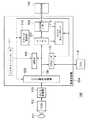
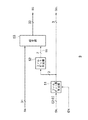
図1は、本発明に係る第1の実施の形態のカメラシステム100を説明するための概略的な構成図である。カメラシステム100は、光学系101、CCD102、A/D変換部103、画像圧縮部104、SDRAM114およびCPU115を有する。
また、画像圧縮部104は、CCD信号処理部105、バス106、バッファ107、SDRAMインターフェイス(SDRAMI/F)108、JPEG処理部109、クロック生成部110、システムコントローラ111、CPUインターフェイス(CPUI/F)112およびメモリコントローラ113を有する。
【0026】
光学系101は、使用者の操作により所望の画像を撮像し、その光信号をCCD102の撮像面上に結像させる。
CCD102は、光学系101により結像された撮像面上の光信号を電気信号に変換し、アナログ画像信号としてA/D変換部103に出力する。
A/D変換部103は、CCD102より入力されたアナログ画像信号を所定の階調のデジタル信号に変換し、画像圧縮部104のCCD信号処理部105に出力する。
【0027】
画像圧縮部104のCCD信号処理部105は、システムコントローラ111の制御に基づいて、入力されるデジタル画像信号をR(赤)、G(緑)、B(青)の各色信号に分離し、各色信号に対して色再現性のためガンマ補正を行い、さらに輝度信号と色差信号を生成する。生成された輝度信号と色差信号からなる画像信号は、バス106を介してバッファ107に出力される。
【0028】
バッファ107は、CCD信号処理部105よりバス106を介して入力される画像信号を順次記憶し、一定量蓄えられたら、メモリコントローラ113の制御に基づいて、SDRAMI/F108に出力する。また、SDRAMI/F108から入力される、SDRAM114より読み出された画像データを一時的に記憶し、バス106を介してJPEG処理部109に出力する。
SDRAMI/F108は、画像圧縮部104の外部メモリであって、メモリコントローラ113の制御に基づいて、バッファ107より入力される所定の単位ごとの画像データをSDRAM114に記憶する。また、SDRAM114に記憶されている画像データを、8×8のブロック単位で読み出し、バッファ107に出力する。
【0029】
JPEG処理部109は、システムコントローラ111の制御に基づいて、SDRAM114より読み出されバッファ107を介して入力される画像信号をJPEG符号化し、符号化ビットストリームを生成し、バス106およびCPUI/F112を介してCPU115に出力する。このJPEG処理部109の構成および動作については後に詳細に説明する。
【0030】
クロック生成部110は、システムコントローラ111の制御に基づいて、画像圧縮部104内の各部で使用するクロックを生成し、その各構成部に提供する。
バス106は、画像圧縮部104内のデータバスを模式的に示したものである。このバス106を介して、CCD信号処理部105からバッファ107へおよびバッファ107からJPEG処理部109への画像データの転送、および、JPEG処理部109からCPUI/F112への符号化ビットストリームの転送などが行なわれる。
【0031】
システムコントローラ111は、CPU115の制御に基づいて動作し、画像圧縮部104の動作、すなわち、入力される画像データのSDRAM114への記憶、SDRAM114に記憶された画像データのJPEG処理部109への転送、JPEG処理部109におけるJPEG符号化、および、符号化された画像データのCPU115への出力などの動作が適切に実行されるように、画像圧縮部104の各構成部を制御する。
CPUI/F112は、CPU115とのインターフェイスであり、CPU115からの制御信号、画像信号の入力、CPU115への制御信号、符号化データの出力などを行なう。
メモリコントローラ113は、システムコントローラ111の制御に基づいて、バッファ107およびSDRAMI/F108を制御し、画像データのSDRAM114への記憶およびSDRAM114に記憶された画像データの読み出しなどを制御する。
【0032】
SDRAM114は、撮影された輝度信号および色差信号からなる画像データを一時的に記憶するメモリである。光学系101〜A/D変換部103で撮影された画像データは、一旦SDRAM114に記憶された後、JPEG処理部109に順次供給され、符号化され、CPU115に出力され、記憶、表示、伝送などに用いられる。
CPU115は、光学系101〜画像圧縮部104およびSDRAM114による所望の画像の撮像、画像処理、画像データの記憶・再生、JPEG符号化、JPEG符号化データの記憶、表示、伝送などの各処理が適切に行なわれ、カメラシステム100が全体として所望の動作をするように、カメラシステム100の各構成部を制御する。
【0033】
このような構成のカメラシステム100においては、まず、使用者の操作により光学系101に所望の画像が撮像されると、CCD102において光信号が電気信号に変換されて画像信号が生成される。その画像信号は、A/D変換部103でアナログ信号からデジタル信号に変換され、さらに画像圧縮部104のCCD信号処理部105において各色信号に分解され、ガンマ補正が施された後、輝度信号と色差信号からなる画像信号に変換される。
この画像信号は、バッファ107、SDRAMI/F108を介して一旦SDRAM114に記憶された後、8×8画素のブロックごとに順次読み出されてJPEG処理部109に入力される。
JPEG処理部109においては、順次入力されるブロックごとの画像データがJPEG符号化され、所定のフォーマットのJPEG符号化データストリームが生成され、CPUI/F112を介してCPU115に出力され、記憶、表示、伝送などの処理が行なわれる。
【0034】
〔JPEG処理部109〕
次に、カメラシステム100のJPEG処理部109の内部構成およびその動作について、図2および図3を参照して説明する。
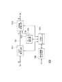
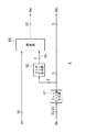
図2は、JPEG処理部109の構成を示すブロック図である。
JPEG処理部109は、DCT・量子化部121、マーカ発生部122、可変長符号化部123、JPEG制御レジスタ124およびJPEGコントローラ125を有する。
なお、JPEG処理部109には1画素8ビットの輝度信号または1画素8ビットの色差信号が、8×8画素単位で入力されるものとする。
【0035】
DCT・量子化部121は、入力される8×8画素の画像データSvにDCTを実行して、64個の周波数成分(DCT係数)に変換し、各係数を、図示せぬ量子化テーブルの対応する値を用いて量子化する。量子化されたDCT係数Sq(11ビット)は、可変長符号化部123に出力される。
【0036】
マーカ発生部122は、JPEGコントローラ125の制御に基づいて、JPEGビットストリームに付加する、そのビットストリームの構造を明確に表現するためのマーカSmを生成し、可変長符号化部123に出力する。
【0037】
可変長符号化部123は、DCT・量子化部121より入力されるDCT係数Sqを可変長符号化し、得られた可変長符号化データと付加ビットデータおよびマーカ発生部122より入力されるマーカSmを、8ビット単位の符号化ビットストリームSdに変換して、JPEG処理部109より出力する。
【0038】
この可変長符号化部123の構成を図3に示す。
図3は、可変長符号化部123の構成を示すブロック図である。
可変長符号化部123は、可変長符号算出部131、可変長符号テーブル132、ビットストリーム生成部133を有する。
【0039】
可変長符号算出部131は、DCT・量子化部121より入力される量子化後のDCT係数Sqに基づいて、可変長符号テーブル132を参照して、DCT係数の大きさに対応する可変長符号化データと、その可変長符号化データの符号長データを検出する。また、そのDCT係数の大きさから付加ビットデータと、その付加ビットデータのデータ長データを検出する。これら検出された可変長符号化データSc、付加ビットデータSa、可変長符号化データ長データScL、付加ビットデータ長データSaLは、各々ビットストリーム生成部133に出力される。
なお、可変長符号化データScは2〜16ビットのデータであり、付加ビットデータSaは0〜11ビットのデータである。したがって、各データ長は、5ビットおよび4ビットのデータとなる。
【0040】
可変長符号テーブル132は、可変長符号化を行なうための符号化テーブルである。
【0041】
ビットストリーム生成部133は、可変長符号算出部131より入力される可変長データである可変長符号化データScおよび付加ビットデータSaを、同じく可変長符号算出部131より入力される可変長符号化データ長データScLおよび付加ビットデータ長データSaLを参照して、8ビット固定長の1つのデータの列に変換し、さらにマーカ発生部122より入力されたマーカSmを付加して、符号化ビットストリームSdとして出力する。
【0042】
JPEG処理部109のJPEG制御レジスタ124は、DCT・量子化部121および可変長符号化部123の動作を制御するデータ、パラメータなどが設定されるレジスタであり、CPU115により、CPUI/F112を介して設定される。
JPEGコントローラ125は、JPEG制御レジスタ124に設定されているデータ、パラメータなどに基づいて、DCT、量子化、マーカ発生、可変長符号化およびビットストリーム生成などの処理が適切に行なわれるように、DCT・量子化部121、マーカ発生部122および可変長符号化部123の動作を制御する。
【0043】
このような構成のJPEG処理部109においては、CPU115からJPEG制御レジスタ124に動作条件などが設定され、これによりJPEGコントローラ125によってDCT・量子化部121および可変長符号化部123が制御され、処理が行なわれる。
すなわち、順次入力される8×8画素ごとの画像データSvを、DCT・量子化部121においてDCTし、量子化する。
量子化されたDCT係数Sqは、可変長符号化部123の可変長符号算出部131において可変長符号化され、可変長符号化データScおよび付加ビットデータSaが生成される。
そして、各々可変長データであるこの可変長符号化データScおよび付加ビットデータSaが、ビットストリーム生成部133において8ビット固定長のデータの列に変換されて、JPEG符号化データストリームSdとして出力される。
【0044】
〔ビットストリーム生成部133〕
次に、上述したJPEG処理部109の、本発明に関わる、可変長符号化部123のビットストリーム生成部133について、図4〜図13を参照して詳細に説明する。
【0045】
まず、図4に示すビットストリーム生成部133の構成について説明する。
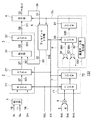
図4は、可変長符号化部123のビットストリーム生成部133の構成を説明するための概略的な構成図である。
ビットストリーム生成部133は、結合部1、データ選択部2、データ結合部3、出力部4、フィルビット付加部5、データ長加算部6、データ長選択部7およびデータ長処理部8を有する。
なお、結合部1は、本発明の可変長データ結合手段の一実施形態である。
データ選択部2は、本発明のデータ選択手段の一実施形態である。
データ結合部3は、本発明のデータ結合手段の一実施形態である。
出力部4は、本発明のデータ出力手段の一実施形態である。
フィルビット付加部5は、本発明のデータ付加部の一実施形態である。
データ長加算部6は、本発明のデータ長生成手段の一実施形態である。
データ長選択部7は、本発明のデータ長選択手段の一実施形態である。
データ長処理部8は、本発明のデータ長処理手段の一実施形態である。
【0046】
結合部1は、可変長符号算出部131から入力した16ビットの可変長符号化データScと11ビットの付加ビットデータSaとを結合して27ビットのデータを生成し、データ選択部2に出力する。
【0047】
この27ビットの結合データは、例えば、結合部1に含まれている図示しないシフト回路とOR回路によって、可変長符号化データScと付加ビットデータSaとがMSB側に詰められた状態となるように生成される。この場合、シフト回路に設定されるビットシフト数は、データに同期して入力されるデータ長の情報(可変長符号化データ長データScLまたは付加ビットデータ長データSaL)に基づいて設定される。
例えば、ともにMSB詰めのデータとして入力される可変長符号化データScおよび付加ビットデータSaが、可変長符号化データScが上位となるようにMSB側へ詰められて結合される場合には、まずシフト回路によって、付加ビットデータSaが可変長符号化データ長データScLだけLSB側にビットシフトされる。次に、このシフトされたデータとMSB詰めの可変長符号化データScとがOR回路によって合成される。これにより、MSB詰めにされた27ビットの結合データが生成される。
【0048】
データ選択部2は、結合部1において可変長符号化データScと付加ビットデータSaとが結合された27ビットの結合データS21、または16ビットのマーカSmを選択信号SELに応じて選択し、データ結合部3に出力するブロックである。図4の例においてセレクタ21およびレジスタ22を有している。
セレクタ21は、結合部1による27ビットの結合データ、またはマーカSmを選択信号SELに応じて選択しデータ結合部3に出力する。
またレジスタ22は、セレクタ21において選択されたデータS21を図示しない所定のシステムクロックに同期して保持し、データ結合部3に出力する。ただし、イネーブル信号ENが無効になった場合には、セレクタ21からの新しいデータの入力を停止する。
【0049】
データ結合部3は、データ選択部2において選択された27ビットのデータS2と、フィルビット付加部5から帰還されるデータS5とを結合して58ビットの結合データを生成し、これを出力部4に出力するブロックである。図4の例において結合部31およびレジスタ32を有している。
【0050】
結合部31は、データ選択部2において選択された27ビットのデータS22と、フィルビット付加部5から帰還されるデータS5とを結合して58ビットの結合データを生成し、これをレジスタ32に出力する。
この58ビットの結合データは、例えば、結合部31に含まれている図示しないシフト回路とOR回路によって、データ選択部2からのデータS22とフィルビット付加部5からの帰還データS5とがMSB側に詰められた状態となるように生成される。この場合、シフト回路に設定されるビットシフト数は、フィルビット付加部5から帰還されるデータS5のデータ長(後述する帰還データ長生成部82の出力データS82)に基づいて設定される。
【0051】
レジスタ32は、結合部31において生成された58ビットの結合データを上述したシステムクロックに同期して保持し、これを出力部4に出力する。
【0052】
出力部4は、後述するデータ処理部8において計算された結合データS3のデータ長StLが32ビットに達している場合、MSB側の32ビット分のデータをビットストリームSoutとして出力し、残りのLSB側のデータを帰還データS4としてフィルビット付加部5に出力する。なお、このときの帰還データS4のデータ長は、データ長StLから32ビット長分を減算したデータ長になる。
また、データ長StLが32ビットに達していない場合は、MSB側の31ビット分のデータを帰還データS4としてそのままフィルビット付加部5に出力する。
【0053】
フィルビット付加部5は、イネーブル信号ENが有効の場合、すなわち可変長符号化データScおよび付加ビットデータSaの結合データがレジスタ22に入力されている場合には、出力部4からの帰還データS4をそのまま帰還データS5としてデータ結合部3に出力する。また、イネーブル信号ENが無効の場合には、データ長処理部8において計算された結合データS3のデータ長StLに基づいてフィルビットを生成し、これを出力部4からの帰還データS4のLSB側に付加する。このフィルビットを付加されたデータが、帰還データS5としてデータ結合部3に出力される。また、このとき生成したフィルビットのデータ長SbLをデータ長処理部8に出力する。
なお、このフィルビット付加部5のさらに詳細な構成については後で説明する。
【0054】
データ長加算部6は、可変長符号化データScおよび付加ビットデータSaにそれぞれ対応したデータ長の情報である可変長符号化データ長データScLおよび付加ビットデータ長データSaLを加算し、この加算結果をデータ長選択部7に出力する。したがって、データ長加算部6による加算結果のデータ長は、結合部1による結合データのデータ長と等しい。
【0055】
データ長選択部7は、データ長加算部6の加算結果のデータ長、または入力されるマーカSmのデータ長SmLを選択信号SELに応じて選択し、選択したデータ長をデータ長処理部8に出力する。なお、JPEGにおいてマーカSmのデータ長SmLは通常16ビットの固定値である。このデータ長選択部7は、図4の例において、セレクタ71およびレジスタ72を有している。
【0056】
セレクタ71は、データ長加算部6の加算結果のデータ長、または入力されるマーカSmのデータ長SmLを選択信号SELに応じて選択し、選択したデータ長をレジスタ72に出力する。
レジスタ72は、セレクタ71において選択されたデータ長をシステムクロックに同期して保持し、データ長処理部8に出力する。ただし、イネーブル信号ENが無効になった場合には、セレクタ71からの新しいデータの入力を停止する。
【0057】
データ長処理部8は、データ長選択部7において選択されたデータ長、およびフィルビット付加部5において生成されたフィルビットのデータ長に基づいて、データ結合部3から出力部4に供給される結合データS3のデータ長StLを算出し、これをフィルビット付加部5および出力部4に出力するブロックである。図4の例においては、レジスタ81、帰還データ長生成部82、データ長加算部83、データ長加算部84およびセレクタ85を有する。
【0058】
レジスタ81は、セレクタ85において選択された結合データ長S85をシステムクロックに同期して保持し、保持されたデータ長を結合データS3のデータ長StLとして、出力部4、フィルビット付加部5および帰還データ長生成部82に出力する。レジスタ81には、レジスタ32に保持されているデータのうちの、出力部4で未だ出力されていない出力待ちデータのデータ長が保持されている。
【0059】
帰還データ長生成部82は、フィルビット付加部5に入力される出力部4からの帰還データS4のデータ長を計算するブロックである。すなわち、データ長StLが32ビットに達して出力部4から32ビットのデータSoutが出力される場合、データ長StLから32ビット長分を減算したデータ長S82を生成し、これをデータ長加算部83およびデータ長加算部84に出力する。また、データ長StLが32ビットに達しない場合には、データ長StLをそのままデータ長S82としてデータ長加算部83およびデータ長加算部84に出力する。
【0060】
データ長加算部83は、帰還データ長生成部82からのデータ長S82とデータ長選択部7において選択されたデータ長とを加算し、この加算結果をセレクタ85に出力する。
データ長加算部84は、帰還データ長生成部82からのデータ長S82とフィルビット付加部5において生成されたフィルビットのデータ長SbLとを加算し、この加算結果をセレクタ85に出力する。
【0061】
セレクタ85は、イネーブル信号ENが無効になった場合にデータ長加算部84による加算結果のデータ長S84を選択し、これをレジスタ81に出力する。また、イネーブル信号ENが有効の場合には、データ長加算部83による加算結果のデータ長S83を選択し、これをレジスタ81に出力する。
【0062】
次に、上述した構成を有するビットストリーム生成部133においてビットストリームが生成される動作を説明する。
【0063】
まず、選択信号SELによって可変長データが選択されている場合について説明する。この場合、データ選択部2のセレクタ21には選択信号SELによって結合部1の出力データが選択されており、レジスタ22には可変長符号化データScと付加ビットデータSaとが結合された27ビットの結合データが保持されている。またこれに対応して、データ長選択部7のセレクタ71には選択信号SELによってデータ加算部6の出力データ長が選択されており、レジスタ72には可変長符号化データ長データScLと付加ビットデータ長データSaLとが加算されたデータ長が保持されている。すなわち、レジスタ72には、レジスタ22に保持された結合データのデータ長が保持されている。
【0064】
また、入力データとして可変長データが選択されている場合、イネーブル信号ENは常に有効であるため、フィルビット付加部5によるフィルビットの生成と付加動作は停止され、出力部4からの帰還データS4はそのまま帰還データS5としてデータ結合部3の結合部31に供給されている。この帰還データS5と、データ選択部2において保持された入力の可変長データS2とが結合部31において結合されて、レジスタ32に保持されている。
【0065】
また、イネーブル信号ENが有効であるため、データ長処理部8のセレクタ85においてデータ長加算部83による加算データ長S83が選択され、これがレジスタ81に保持されている。この加算データ長S83はデータ選択部2のレジスタ22に保持された可変長データS2のデータ長と、帰還データ長生成部82において生成された帰還データS4のデータ長S82とが加算されたデータであり、レジスタ32に保持される前の結合データS31のデータ長に相当する。
【0066】
この状態で可変長符号化データScおよび付加ビットデータSaが順次入力されると、データ結合部3のレジスタ32に保持された未出力データのデータ長StLが32ビットに満たない場合、出力部4から帰還される未出力の帰還データS5のLSB側に、レジスタ22の可変長データS2のMSB側が結合され、この結合データがレジスタ32に順次保持される。また、データ長処理部8のレジスタ81には、レジスタ72に入力される可変長データS2のデータ長が順次積算されて保持される。したがって、未出力データのデータ長StLは可変長データ(可変長符号化データSc、付加ビットデータSa)の入力とともに長くなる。
【0067】
そしてこの未出力データ長StLが32ビットに達すると、レジスタ32に保持された未出力データのMSB側32ビットは出力部4から出力データSoutとして出力され、残りのLSB側26ビットはフィルビット付加部5に帰還される。また、データ長処理部8の帰還データ長生成部82においては、未出力データのデータ長StLから出力データ長(32ビット)が減算される。したがって、未出力データ長StLが32ビットに達して出力部4から32ビットづつデータが出力される度に、未出力データのデータ長StLは32ビットづつ短くなる。
【0068】
このように、順次入力される可変長符号化データScおよび付加ビットデータSaはデータ結合部3において順次結合されて保持され、この保持されたデータのMSB側32ビットのデータが出力部4から順次出力される。
出力部4から出力される32ビットのビットストリームSoutは、さらにビットストリーム生成回路133の図示しない回路によって8ビットのビットストリームに変換されて、画像圧縮部104のバス106に順次出力される。例えば、システムクロックの4倍の周波数を有するクロックに同期して動作するセレクタ回路によりこの生成された32ビットから8ビットづつのデータを順次選択し、選択されたデータを8ビットのレジスタに順次保持して出力することにより、8ビットのビットストリームが得られる。
【0069】
次に、選択信号SELが変化して入力データが可変長データからマーカSmに切り換えられる場合について説明する。この場合、データ選択部2のセレクタ21においてはマーカSmが選択されてレジスタ22に保持される。また、データ長選択部7のセレクタ71においてはマーカSmのデータ長SmLが選択されてレジスタ72に保持される。すなわち、レジスタ22にはマーカSmが保持され、レジスタ72にはマーカSmのデータ長SmLが保持される。
【0070】
この選択信号SELの変化に応じてイネーブル信号ENが無効になると、フィルビット付加部5において未出力データ長StLに応じたデータ長のフィルビットが生成されて帰還データS4のLSB側に付加されるとともに、このフィルビット長SbLがデータ長処理部8のデータ長加算部84に出力される。また、データ長処理部8のセレクタ85において、このフィルビット長SbLと帰還データ長S82とが加算された加算データ長S84が選択され、これがレジスタ81に保持される。また、イネーブル信号ENが無効なので、レジスタ22およびレジスタ72による新たなデータの保持が停止される。すなわち、レジスタ22のマーカSmおよびレジスタ72のデータ長SmLはそのまま保持され続ける。
【0071】
こうして一旦フィルビットが帰還データS4に付加されると、レジスタ32に保持される未出力データ長StLは1バイトの整数倍のデータ長になり、この後のクロックサイクルで生成されるフィルビット長SbLはゼロになる。したがって、レジスタ81に保持される未出力データ長StLは一定となる。
また、レジスタ22に保持されたマーカSmは、フィルビット付加部5において付加されたフィルビットの末尾に結合されてレジスタ32に保持されるが、未出力データ長StLにマーカSmのデータ長SmLが加算されていないためマーカSmの部分は未出力データの範囲に含まれない。したがって、この部分が出力部4から出力されることはない。
【0072】
ここで、再び選択信号SELによる入力データの選択がマーカSmから可変長データに切り換わり、これに応じてイネーブル信号ENが有効状態に戻ると、停止されていたレジスタ22およびレジスタ72による新たなデータの保持が再開される。
また、レジスタ81には未出力データ長StLにマーカデータ長SmLが加算されたデータ長が保持されるので、フィルビットの末尾に結合されたマーカSmを含む結合データS3が出力部4による出力対象のデータとなる。
以降、可変長データの結合と32ビットデータの出力によるビットストリームの上述した生成動作が反復される。
【0073】
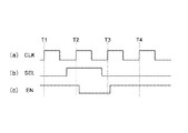
ここで、上述したビットストリームの生成動作の具体例について、図5および図6を参照しながら説明する。図5は、システムクロックに対する選択信号SELおよびイネーブル信号ENのタイミング例を示すタイミング図である。また図6は、図5に示すタイミング図の時刻T1〜時刻T4においてレジスタ22およびレジスタ32に保持されるデータの例を示す図である。
なお、図5の例においては選択信号SELがハイレベルの場合にマーカSmが選択され、ローレベルの場合に可変長データが選択される。イネーブル信号ENは、ハイレベルの場合に有効となり、ローレベルの場合に無効となる。また、図4の各レジスタには、システムクロックCLKの立ち上がりに同期してデータが保持される。
【0074】
時刻T1:
セレクタ21において可変長データが選択されており、結合部1からの11ビットの可変長データがレジスタ22に保持される。またレジスタ32には7ビットの未出力データが保持される。
【0075】
時刻T2:
選択信号SELがハイレベルとなり、セレクタ21において16ビットのマーカSmが選択されてレジスタ22に保持される。また、時刻T1にレジスタ22に保持されていた11ビットの可変長データが7ビットの未出力データのLSB側に結合されて、レジスタ32に保持される。
【0076】
時刻T3:
選択信号SELがハイレベルとなり、レジスタ22には結合部1からの出力データが選択されているが、イネーブル信号ENが無効となっているため、レジスタ22に保持されたマーカSmはそのまま保持され続ける。
また、イネーブル信号ENが無効であるためフィルビット付加部5におけるフィルビットの生成および付加動作が有効となり、レジスタ32に保持された未出力データのデータ長18ビット(7ビット+11ビット)に応じた6ビットのフィルビットが生成される。未出力データのデータ長は32ビットに達していないので、この未出力データはそのまま帰還データS4としてフィルビット付加部5に帰還され、LSB側に6ビットのフィルビットが付加される。これにより24ビットの帰還データS5が生成されて、結合部31に入力される。この24ビットの帰還データS5はMSB側に詰められて結合部31から出力され、そのままレジスタ32に保持される。
【0077】
時刻T4:
イネーブル信号ENが有効となりレジスタ22の保持動作が再開されることにより、結合部1からの20ビットの可変データがクロックの立ち上がりに同期してレジスタ22に保持される。
また、レジスタ22に保持されていた16ビットのマーカSmは、結合部31において24ビットの帰還データS5のLSB側に結合されてレジスタ32に保持される。
【0078】
このように、6ビットのフィルビットがフィルビット付加部5において未出力データの末尾側に付加されることにより、マーカSmのデータ境界はビットストリームのバイト境界と一致する。
【0079】
[フィルビット付加部5]
次に、上述したビットストリーム生成部133のフィルビット付加部5について、図7〜図13を参照して詳細に説明する。
【0080】
図7は、図4に示したフィルビット付加部5を説明するための概略的な構成図であり、この図においてフィルビット付加部5は、フィルビット長生成部51、フィルビット生成部および結合部53を有する。
なお、フィルビット長生成部51は、本発明の調整データ長設定手段の一実施形態である。
フィルビット生成部52は、本発明の調整データ生成手段の一実施形態である。
結合部53は、本発明の付加手段の一実施形態である。
【0081】
結合部53は、出力部4から入力した帰還データS4のLSB側にフィルビット生成部52で生成されたフィルビットSbを付加し、全体をMSB側に詰めた32ビットの帰還データS5を生成する。
帰還データS4はMSB側に詰められているので、例えば、結合部53に含まれている図示しないシフト回路によりフィルビットSbをMSBから帰還データS4のデータ長StLだけLSB側にビットシフトさせ、このシフトされたフィルビットSbと帰還データS4とを図示しないOR回路により合成することで、フィルビットSbが付加された帰還データS5を生成することができる。
【0082】
フィルビット長生成部51は、データ長処理部8において計算された未出力データ長StLの下位3ビットに応じてフィルビットのデータ長SbLを生成し、これをフィルビット生成部52およびデータ長処理部8のデータ長加算部84に出力する。
【0083】
図8は、図7に示したフィルビット長生成部51の一例を説明するための概略的な構成図であり、この図においてフィルビット長生成部51は、3ビット入力のNOT回路511および加算部512を有している。
このフィルビット長生成部51においては、未出力データ長StLの下位3ビットがNOT回路511において各ビットごとにビット値が反転されており、さらに反転後のデータの最下位ビットに値”1”のデータが加算されて、3ビットのフィルビット長SbLが生成されている。
ただし、イネーブル信号ENが有効の場合には、図示しないゲート回路等によってフィルビット長は強制的にゼロに設定されるため、後述のフィルビット生成部52においてフィルビットは生成されない。したがって、上述した結合部53に入力される帰還データS4はそのまま帰還データS5としてデータ結合部3に出力される。
【0084】
図9は、未出力データ長StLとフィルビット長SbLとの対応例を示す図である。図9から分かるように、未出力データ長StLの下位3ビットが値”000”の場合はフィルビットの挿入が必要なく、またフィルビットが挿入必要な場合には、未出力データ長StLの下位3ビットにフィルビット長SbLが加算された結果が値”1000”となるように、フィルビット長SbLが設定されている。したがって、値”1000”から未出力データ長StLの下位3ビットが減算されることによってフィルビット長SbLが得られることになり、これは値”111”からの減算結果に値”1”が加算された結果と等しくなる。すなわち、未出力データ長StLの下位3ビットがビット反転された結果に値”1”が加算される図8のフィルビット長生成部51によって、フィルビット長SbLが生成される。
【0085】
なお、図8に示すフィルビット長生成部は一例であり、他の構成も可能である。より一般的な例として、例えば未出力データ長StLを境界の単位となるデータ長(バイト境界の場合には8ビット)で除した商を計算し、この計算結果と当該単位データ長との差分としてフィルビット長を求めることもできる。
以上がフィルビット長生成部51の説明である。
【0086】
次に図7のフィルビット生成部52について説明する。
フィルビット生成部52は、フィルビット長生成部51において生成されたフィルビット長SbLに応じてMSB詰めにされたフィルビットを生成し、これを結合部53に入力する。
【0087】
図10は、図7に示したフィルビット生成部の一例を説明するための概略的な構成図であり、この図においてフィルビット生成部52はセレクタ521を有する。
図11に示すように、フィルビット長(0ビット〜7ビット)とMSB詰めにされた8種類のフィルビットとは一対一に対応している。この8種類のフィルビットがセレクタ521に入力されており、フィルビット長SbLに応じてこれらのフィルビットから対応するフィルビットが選択され、結合部53に出力される。
【0088】
図12は、図7に示したフィルビット生成部の他の例を説明するための概略的な構成図であり、この図においてフィルビット生成部52’は、セレクタ521’、およびデータ生成部522’〜データ生成部525’を有する。
【0089】
データ生成部522’〜データ生成部525’は、フィルビット長SbLの最下位ビットF0、第1ビットF1の値に応じた2ビットのデータF1v、および第2ビットF2の値に応じた4ビットのデータF2vをそれぞれ所定の順序で結合して7ビットのデータを生成し、これをセレクタ521’に出力する。
セレクタ521’は、データ生成部522’〜データ生成部525’の生成データから、フィルビット長SbLの上位2ビットのデータに応じて一のデータを選択し、フィルビットSbとして出力する。
【0090】
図13は、図12に示したフィルビット生成部52’において生成されるフィルビットとフィルビット長との対応例を示す図である。フィルビット長SbLのビットF1に対応する2ビットのデータF1vは、ビットF1を2ビット分連ねたデータとして生成され、ビットF2に対応する4ビットのデータF2vは、ビットF2を4ビット分連ねたデータとして生成される。
【0091】
このデータF1v、データF2vおよびビットF0が{F0,F1v,F2v}、{F1v,F0,F2v}、{F2v,F0,F1v}および{F2v,F1v,F0}という4通りの組み合わせで結合されることにより、MSB詰めにされた7ビットのフィルビットを図11と同じ対応関係で生成することができる。また、これらの4通りの組み合わせは、それぞれフィルビット長SbLの上位2ビットのデータ(ビットF1およびビットF2)と一対一に対応しているので、この2ビットのデータを使って4通りの組み合わせのうちの1つを選択することにより、図11と同じ対応関係で、フィルビット長SbLからフィルビットSbを生成することができる。
図12に示したフィルビット生成部52’は、図10のフィルビット生成部52に比べてセレクタ回路で選択されるデータの数が半分になるので、フィルビット生成部52より回路規模を小さくすることができる。
【0092】
以上説明したように、第1の実施の形態の図4に示すビットストリーム生成部133によれば、データ結合部3において結合されたデータで未出力のデータのデータ長StLが32ビットに達した場合、当該未出力データの上記MSB側から32ビット分のデータが出力部4において出力され、当該出力後の残りのデータが帰還データS4としてフィルビット付加部5に出力される。また、未出力データのデータ長が32ビットに達しない場合は、この未出力データがそのまま帰還データS4としてフィルビット付加部5に出力される。選択信号SELに応じて選択された入力データが可変長データの場合、フィルビット付加部5に入力された帰還データS4はそのまま帰還データS5としてデータ結合部3に出力され、選択信号SELに応じて選択された入力データがマーカSmの場合には、帰還データS4のデータ長StLと1バイトの整数倍のデータ長との差分のデータ長を有するフィルビットSbがフィルビット付加部5において生成され、帰還データS4のLSB側に付加された後、帰還データS5としてデータ結合部3に出力される。データ結合部3においては、帰還データS5のLSB側にデータ選択部2からの入力データのMSBが結合されて、出力部4に供給される。したがって、システムクロックに同期して順次入力される可変長データは、同じシステムクロックに同期して順次32ビットのデータに変換されるとともに、マーカSmが挿入される場合にも、フィルビットの生成および付加動作による1クロックの待ち時間が発生するだけなので、例えばソフトウェアにより同一の機能を実現させる場合に比べて、フィルビットの挿入処理を含むビットストリーム生成処理を大幅に効率化できる。
【0093】
第2の実施の形態
次に、本発明に係る第2の実施の形態について、図14〜図17を参照して説明する。
上述した第1の実施の形態においては、フィルビットの生成および付加動作が行われる場合に、イネーブル信号ENを受けたレジスタ22およびレジスタ72において新しいデータの入力が停止される。このため、データの入力に少なくとも1クロックの待ち時間が発生してしまう問題がある。本実施の形態は、この待ち時間を発生することなしにフィルビットの生成および付加動作を実行できるものである。
【0094】
本実施の形態のカメラシステムの全体の構成および動作、そのJPEG処理部の内部構成および動作、および、その可変長符号化部の構成については、図1〜図3を参照して上述した第1の実施の形態のカメラシステム100と同じなので、その説明は省略する。
以後、本実施の形態の特徴である、可変長符号化部123のビットストリーム生成部133’について説明する。
【0095】
〔ビットストリーム生成部133’〕
まず、ビットストリーム生成部133’の構成について図14を参照して説明する。
図14は、本発明に係る第2の実施の形態のビットストリーム生成部133’を説明するための概略的な構成図である。ビットストリーム生成部133’は、結合部1、データ選択部2’、データ結合部3、出力部4、フィルビット付加部5’、データ長加算部6、データ長選択部7’、データ長処理部8’およびデータ長加算部9を有する。ただし、図4と図14の同一符号は同一の構成要素を示している。
また、フィルビット付加部5’は、本発明のデータ付加部の一実施形態である。
データ長加算部6は、本発明の第1のデータ長生成手段の一実施形態である。
データ長処理部8’は、本発明のデータ長処理手段の一実施形態である。
データ長加算部9は、本発明の第2のデータ長生成手段の一実施形態である。
【0096】
結合部1は、可変長符号算出部131から入力した16ビットの可変長符号化データScと11ビットの付加ビットデータSaとを結合して27ビットのデータを生成し、データ選択部2’に出力する。
【0097】
データ選択部2’は、結合部1において可変長符号化データScと付加ビットデータSaとが結合された27ビットの結合データS21、または後述するフィルビット付加部5’においてフィルビットが付加されたマーカSm’を選択信号SELに応じて選択し、データ結合部3に出力する。
図4におけるデータ選択部2との違いは、レジスタ22’がイネーブル信号ENに応じてデータの入力を停止されないことにある。
【0098】
データ結合部3は、データ選択部2において選択された27ビットのデータS2と、出力部4から帰還されるデータS4とを結合して58ビットの結合データを生成し、これを出力部4に出力する。
【0099】
出力部4は、後述するデータ長処理部8’において計算された結合データS3のデータ長StLが32ビットに達している場合、MSB側の32ビット分のデータをビットストリームSoutとして出力し、残りのLSB側のデータを帰還データS4としてデータ結合部3に帰還する。なお、このときの帰還データS4のデータ長は、データ長StLから32ビット長分を減算したデータ長になる。また、データ長StLが32ビットに達していない場合は、MSB側の31ビット分のデータを帰還データS4としてデータ結合部3に帰還する。
【0100】
フィルビット付加部5’は、データ長処理部8’において計算された結合部31の結合データS31のデータ長SkLに基づいてフィルビットを生成し、入力される16ビットのマーカSmのMSB側に付加する。このフィルビットを付加されたデータが、マーカSm’としてデータ選択部2に出力される。また、このとき生成したフィルビットのデータ長SbLをデータ長加算部9に出力する。
【0101】
図15は、このフィルビット付加部5’を説明するための概略的な構成図であり、この図においてフィルビット付加部5’は、フィルビット長生成部51’、フィルビット生成部52および結合部53’を有している。ただし、図7と図15の同一符号は同一の構成要素を示している。
図7に示すフィルビット付加部5では、結合部53において、入力される帰還データS4のLSB側にフィルビットが付加されるのに対して、図15に示すフィルビット付加部5’の結合部53’では、入力されるマーカSmのMSB側にフィルビットが付加される。またフィルビット長生成部51’はイネーブル信号ENに応じて出力値が制御されなくなる。これら点においてフィルビット付加部5とフィルビット付加部5’とは異なっているが、その他の構成(フィルビット生成部52)については同一である。
【0102】
データ長加算部6は、可変長符号化データScおよび付加ビットデータSaにそれぞれ対応したデータ長の情報である可変長符号化データ長データScLおよび付加ビットデータ長データSaLを加算し、この加算結果をデータ長選択部7’に出力する。したがって、データ長加算部6による加算結果のデータ長は、結合部1による結合データのデータ長と等しい。
【0103】
データ長加算部9は、マーカSmおよびフィルビットSbにそれぞれ対応したデータ長の情報であるマーカSmLおよびフィルビット長SbLを加算し、この加算結果をデータ長選択部7’に出力する。したがって、データ長加算部9による加算結果のデータ長は、フィルビット付加部5’においてマーカSmにフィルビットSbが付加されたマーカSm’のデータ長と等しい。
【0104】
データ長選択部7’は、データ長加算部6の加算結果のデータ長、またはデータ長加算部9の加算結果のデータ長を選択信号SELに応じて選択してデータ長処理部8’に出力する。
図4におけるデータ長選択部7との違いは、レジスタ72’がイネーブル信号ENに応じてデータの入力を停止されないことにある。
【0105】
データ長処理部8’は、データ長選択部7’において選択されたデータ長に基づいて、データ結合部3から出力部4に供給される結合データS3のデータ長StLを算出し、これを出力部4に出力する。またデータ結合部3の結合部31におけるデータ長StLをフィルビット付加部5’に出力する。
図14に示すデータ長処理部8’は、データ長加算部84およびセレクタ85が削除され、データ長加算部83の加算結果がそのままレジスタ81に出力されている点において図4に示すデータ長処理部8と異なっているが、その他の各構成(レジスタ81、帰還データ長生成部82、データ長加算部83)についてはデータ長処理部8と同一である。
【0106】
次に、上述した構成を有するビットストリーム生成部133’においてビットストリームが生成される動作を説明する。
【0107】
まず、選択信号SELによって可変長データが選択されている場合について説明する。この場合、データ選択部2’のセレクタ21には選択信号SELによって結合部1の出力データが選択されており、レジスタ22’には可変長符号化データScと付加ビットデータSaとが結合された27ビットの結合データが保持されている。またこれに対応して、データ長選択部7’のセレクタ71には選択信号SELによってデータ加算部6の出力データ長が選択されており、レジスタ72’には可変長符号化データ長データScLと付加ビットデータ長データSaLとが加算されたデータ長が保持されている。すなわち、レジスタ72’には、レジスタ22’に保持された結合データのデータ長が保持されている。
【0108】
この状態で可変長符号化データScおよび付加ビットデータSaが順次入力されると、データ結合部3のレジスタ32に保持された未出力データのデータ長StLが32ビットに満たない場合、出力部4から帰還される未出力の帰還データS4のLSB側に、レジスタ22’の可変長データS2のMSB側が結合され、この結合データがレジスタ32に順次保持される。また、データ長処理部8’のレジスタ81には、レジスタ72’に入力される可変長データS2のデータ長が順次積算されて保持される。したがって、未出力データのデータ長StLは可変長データ(可変長符号化データSc、付加ビットデータSa)の入力とともに長くなる。
【0109】
そしてこの未出力データ長StLが32ビットに達すると、レジスタ32に保持された未出力データのMSB側32ビットは出力部4から出力データSoutとして出力され、残りのLSB側26ビットはデータ結合部3に帰還される。また、データ長処理部8’の帰還データ長生成部82においては未出力データのデータ長StLから出力データ長(32ビット)が減算される。したがって、未出力データ長StLが32ビットに達して出力部4から32ビットづつデータが出力される度に、未出力データのデータ長StLは32ビットづつ短くなる。
【0110】
このように、順次入力される可変長符号化データScおよび付加ビットデータSaはデータ結合部3において順次結合されて保持され、この保持されたデータのMSB側32ビットのデータが出力部4から順次出力される。
出力部4から出力される32ビットのビットストリームSoutは、さらにビットストリーム生成回路133’の図示しない回路によって8ビットのビットストリームに変換されて、画像圧縮部104のバス106に順次出力される。例えば、システムクロックの4倍の周波数を有するクロックに同期して動作するセレクタ回路によりこの生成された32ビットから8ビットづつのデータを順次選択し、選択されたデータを8ビットのレジスタに順次保持して出力することにより、8ビットのビットストリームが得られる。
【0111】
次に、選択信号SELが変化して入力データが可変長データからマーカSmに切り換えられる場合であるが、この場合、入力されるデータが可変長データからマーカSmに切り換わっただけであるため、上述したデータの結合と出力の動作は入力データが可変長データの場合と同様に行われる。
【0112】
図4のビットストリーム生成部133と図14のビットストリーム生成部133’との違いは、選択信号SELの状態に係わらずマーカSmに付加すべきフィルビットが常に生成され、このフィルビットを付加されたマーカSm’がレジスタ22’に保持される前に確定していることにある。
【0113】
レジスタ22’に保持される前のマーカSmに対して付加すべきフィルビット長の値は、帰還データS4のデータ長と、既にレジスタ22’に保持された入力データのデータ長との和(すなわち次のクロックでレジスタ32に保持される未出力データS31のデータ長)が、8ビット長の整数倍のデータ長に対して有する差分に応じて決定される。したがって、この和のデータ長に相当するデータ加算部83のデータ長SkLがフィルビット付加部5’に供給されると、選択信号SELの状態とは無関係に、フィルビット長SbLおよびフィルビットSbが決定される。このため、マーカSmとして挿入すべきデータがシステムクロックに同期してセットされると、次のクロックでレジスタ22’に入力データが保持されるより前に、フィルビット付加部5’においてフィルビットが付加されたマーカSm’が生成され、選択信号SELに応じててレジスタ22’に供給される。
【0114】
ここで、上述したビットストリームの生成動作の具体例について、図16および図17を参照しながら説明する。図16は、システムクロックに対する選択信号SELのタイミング例を示すタイミング図である。また図17は、図16に示すタイミング図の時刻T1’〜時刻T3’においてレジスタ22’およびレジスタ32に保持されるデータの例を示す図である。
なお、図16の例においては選択信号SELがハイレベルの場合にマーカSmが選択され、ローレベルの場合に可変長データが選択される。また、図14の各レジスタには、システムクロックCLKの立ち上がりに同期してデータが保持される。
【0115】
時刻T1’:
セレクタ21において可変長データが選択されており、結合部1からの7ビットの可変長データがレジスタ22’に保持される。またレジスタ32には11ビットの未出力データが保持される。
また、この時刻T1’から時刻T2’の間において、レジスタ22’に保持された可変長データのデータ長と、レジスタ32に保持された未出力データのデータ長とが加算されたデータ長(7ビット+11ビット=18ビット)がデータ長SkLとしてフィルビット付加部5’に供給される。フィルビット付加部5’において、この供給されたデータ長SkLに基づいて6ビットのフィルビットが生成され、生成されたフィルビットがマーカSmのMSB側に付加されてデータ選択部2’に供給される。
【0116】
時刻T2’:
選択信号SELがハイレベルとなり、セレクタ21においてフィルビット付加部5’のマーカSm’が選択されてレジスタ22’に保持される。また、時刻T1’においてレジスタ22’に保持されていた7ビットの可変長データが11ビットの未出力データのLSB側に結合されて、レジスタ32に保持される。これにより、未出力データのデータ長は18ビットとなる。
【0117】
時刻T3’:
選択信号SELがハイレベルとなり、レジスタ22’には結合部1からの14ビットの可変長データが保持される。また、時刻T2’にレジスタ22’に保持されていたフィルビットとマーカSmの結合データは、18ビットの未出力データのLSB側に結合されて、レジスタ32に保持される。
【0118】
このように、6ビットのフィルビットがフィルビット付加部5’においてマーカSmのMSB側に付加されることにより、マーカSmのデータ境界はビットストリームのバイト境界と一致する。
【0119】
以上説明したように、第2の実施の形態の図14に示すビットストリーム生成部133’によれば、データ結合部3において結合されたデータで未出力のデータのデータ長StLが32ビットに達した場合、当該未出力データのMSB側から32ビット分のデータが出力部4において出力され、当該出力後の残りのデータが帰還データS4としてデータ結合部3に出力される。また、未出力データのデータ長が32ビットに達しない場合は、この未出力データがそのまま帰還データS4としてデータ結合部3に出力される。またフィルビット付加部5’において、入力データS2と帰還データS4のデータ長がデータ長加算部83において加算されたデータ長SkLと、1バイトの整数倍のデータ長との差分のデータ長を有するフィルビットSbが生成される。この生成されたフィルビットSbは、入力されるマーカSmのMSB側に付加されてデータ選択部2’に出力される。データ選択部2’において、上記フィルビットが付加されたマーカSm’、または順次入力される可変長データが選択信号SELに応じて選択される。データ結合部3において、この選択されたデータのMSB側が帰還データS4のLSB側に結合されて出力部4に供給される。したがって、システムクロックに同期して順次入力される可変長データは、同じシステムクロックに同期して順次32ビットのデータに変換されるとともに、マーカSmが挿入される場合において、フィルビットの生成および付加動作による待ち時間が発生しないので、上記した第1の実施の形態に比べて、フィルビットの挿入処理を含むビットストリーム生成処理をさらに効率化できる。またビットストリーム生成部133’においては、データ長処理部8のセレクタ85やデータ長加算部84が削除されるので、第1の実施の形態に比べて回路規模を小さくすることができる。また、イネーブル信号ENによる制御が不要になるので、制御方法を簡易化できる。
【0120】
なお、本発明は本実施の形態に限られるものではなく、種々の改変が可能である。
たとえば、図1に示したカメラシステム、図2に示したJPEG処理部および図3に示した可変長符号化部の構成は、各々これに限られるものではなく、任意の構成でよい。
また、本発明に係る図4および図14に示したビットストリーム生成部の構成や、図7、図8、図10、図12および図15に示したフィルビット付加部の構成なども、任意に変更してよい。
【0121】
また、本発明は、JPEG符号化以外の任意の符号化データや、符号化の結果ではない任意の可変長データに対しても適用可能である。
また、本発明は、JPEG符号化、画像符号化に限定されるものではない。また、カメラシステムにのみ限定されるものではない。可変長符号化処理を含む任意の信号処理装置に対しても適用可能である。
【0122】
【発明の効果】
このように本発明によれば、フィルビットの挿入処理を効率よく行なうことにより、より小さい回路規模で、簡単な構成、制御により、可変長データの列から所定のビット幅の固定長データの列を生成するデータストリーム生成装置とその方法を提供することができる。
また、フィルビットの挿入処理を効率よく行なうことにより、より小さい回路規模で、簡単な構成、制御により、所望のデータを可変長符号化し効率よく所定のデータストリームを生成する可変長符号化データストリーム生成装置とその方法を提供することができる。
さらに、所望の画像を撮影し、撮影した画像データを可変長符号化するカメラシステムであって、特に、より小さい回路規模で、簡単な構成、制御により、撮影した画像データを可変長符号化し、効率よく画像データストリームを生成するカメラシステムを提供することができる。
【図面の簡単な説明】
【図1】本発明に係る第1の実施の形態のカメラシステムを説明するための概略的な構成図である。
【図2】図1に示したカメラシステムのJPEG処理部を説明するための概略的な構成図である。
【図3】図2に示したJPEG処理部の可変長符号化部を説明するための概略的な構成図である。
【図4】図3に示した可変長符号化部のビットストリーム生成部の構成を説明するための概略的な構成図である。
【図5】システムクロックに対する選択信号およびイネーブル信号のタイミング例を示すタイミング図である。
【図6】図5に示すタイミング図の各時刻において各レジスタに保持されるデータの例を示す図である。
【図7】図4に示したフィルビット付加部を説明するための概略的な構成図である。
【図8】図7に示したフィルビット長生成部を説明するための概略的な構成図である。
【図9】未出力データ長とフィルビット長との対応例を示す図である。
【図10】図7に示したフィルビット生成部を説明するための概略的な構成図である。
【図11】フィルビット長とフィルビットとの対応例を示す図である。
【図12】図7に示したフィルビット生成部の他の例を説明するための概略的な構成図である。
【図13】図12に示したフィルビット生成部によって生成されるフィルビットとフィルビット長との対応例を示す図である。
【図14】本発明に係る第2の実施の形態のビットストリーム生成部を説明するための概略的な構成図である。
【図15】図14に示すビットストリーム生成部のフィルビット付加部を説明するための概略的な構成図である。
【図16】システムクロックに対する選択信号のタイミング例を示すタイミング図である。
【図17】図16に示すタイミング図の各時刻において各レジスタに保持されるデータの例を示す図である。
【符号の説明】
1…結合部、2…データ選択部、3…データ結合部、4…出力部、5,5’…フィルビット付加部、6…データ長加算部、7…データ長選択部、8,8’…データ長処理部、9…データ長加算部、21…セレクタ、22…レジスタ、31…結合部、32…レジスタ、51…フィルビット長生成部、52…フィルビット生成部、53,53’…結合部、81…結合データ長生成部、82…セレクタ、83…レジスタ、84…データ長加算部、100…カメラシステム、101…光学系、102…CCD、103…A/D変換部、104…画像圧縮部、105…CCD信号処理部、106…バス、107…バッファ、108…SDRAMI/F、109…JPEG処理部、110…クロック生成部、111…システムコントローラ、112…CPUI/F、113…メモリコントローラ、114…SDRAM、115…CPU、121…DCT・量子化部、122…マーカ発生部、123…可変長符号化部、124…JPEG制御レジスタ、125…JPEGコントローラ、131…可変長符号算出部、132…可変長符号テーブル、133…ビットストリーム生成部、511…ビット反転部、512…加算部、521,521’…セレクタ、522’〜525’…データ生成部[0001]
BACKGROUND OF THE INVENTION
The present invention relates to a data stream generation apparatus and method for generating a data string having a predetermined data length from an input data string, and to a predetermined data stream by applying such an apparatus and method to variable-length encoding such as JPEG. The present invention relates to a variable-length data stream generation apparatus and method for generating a signal, and a camera system that variably encodes a captured image signal and processes the signal.
[0002]
[Prior art]
There are various methods for encoding image data and audio data. A typical example is JPEG (Joint Photographic Experts Group) as a widely used method for encoding still images. is there.
In JPEG, various control codes called markers are used to define the structure of a compression-encoded bit stream.
[0003]
For example, in a coding method using DCT (Discrete Cosine Transform) adopted in JPEG, a DC component of a DCT coefficient having a high correlation between blocks is a difference between adjacent blocks in order to reduce the amount of information. Encoded with a value. For this reason, when an error occurs in the data for some reason when transferring JPEG compression-encoded data, the subsequent blocks are greatly affected. In order to prevent this, a marker called a restart marker (RSTm) for clearing the DC component value held in the JPEG image data is an MCU (Minimum Coded Unit) which is a set of blocks of 8 × 8 pixels, for example. ) Are inserted into the bitstream for each unit called.
In addition, there are markers such as SOI (Start Of Image) indicating the start of one image and EOI (End Of Image) indicating the end of the image, for example.
[0004]
These markers are assigned a 2-byte code having a 1-byte header represented by FFh (h indicates hexadecimal notation). For example, a code of FFD0h to FFD7h is assigned to RSTm, a code of FFD8h is assigned to SOI, and a code of FFD9h is assigned to EOI.
[0005]
By the way, in JPEG, these markers are required to be inserted at appropriate positions with respect to the boundary of the byte unit in the compression encoded bit stream. However, since JPEG compression coding is variable length coding, if a marker is inserted into a compression coded bit stream as it is, the insertion position of the marker relative to the byte boundary is not constant.
Therefore, when inserting a marker into a compression-encoded bitstream, bit data (referred to as fill bits) having an appropriate data length for adjusting the insertion position is generated, and this is inserted before the marker. Need to be inserted into.
[0006]
[Problems to be solved by the invention]
In this way, when a stream of image data compressed and encoded by JPEG, for example, is generated, various markers are inserted into the bit stream generated by compression and encoding. For each insertion, the above-described fill bit must be generated and inserted before the marker. Since such processing requires complicated control, conventionally such processing has been performed by software. However, there are many processes that require many execution cycles in software, such as a process of bit-shifting and combining data, and image data often has a large amount of data. There is a problem that is difficult to obtain.
Further, even when such processing is realized by hardware, there is a problem that the configuration is complicated and the circuit scale becomes large. This is a particular problem when trying to construct such a circuit on an LSI, and improvement is desired.
[0007]
The present invention has been made in view of such circumstances, and an object thereof is to efficiently perform fill bit insertion processing from a data string that is sequentially input with a simple circuit configuration and control with a smaller circuit scale. An object of the present invention is to provide a data stream generating apparatus and method for generating a data string having a predetermined data length.
Also, another object of the present invention is to perform variable fill bit insertion processing to produce a predetermined data stream by variable length coding of desired data with a small circuit scale and simple configuration and control. An object of the present invention is to provide an apparatus and method for generating a long encoded data stream.
Still another object of the present invention is a camera system that captures a desired image and variable-length-encodes the captured image data. In particular, the captured image has a smaller circuit scale and simple configuration and control. It is an object of the present invention to provide a camera system that generates an image data stream obtained by variable-length encoding data.
[0008]
[Means for Solving the Problems]
In order to achieve the above object, the data stream generation device according to the first aspect of the present invention sequentially combines predetermined head bits of sequentially input data to the end bit side of previously input data, A data stream generation device that sequentially outputs data of a predetermined data length from the first bit side of the combined data, and when the data length of the combined data that has not been output reaches the predetermined data length The data corresponding to the predetermined data length is output from the first bit side of the non-output data, the remaining data after the output is output as feedback data, and the data length of the non-output data reaches the predetermined data length. If not, data output means for outputting the non-output data as the feedback data, and if the input data is predetermined data, the data length of the feedback data A data adding means for generating adjustment data having a data length that is a difference from a data length that is an integral multiple of a fixed unit data length, and adding the adjustment data to the tail bit side of the feedback data; and the tail bit side of the feedback data Data combining means for combining the leading bits of the input data and supplying the combined data as the unoutput data to the data output means;Then, based on the input data length information sequentially input corresponding to the input data, the data length of the input data is integrated, and when the integrated data length reaches the predetermined data length, Data length processing means for subtracting a predetermined data length and adding the data length of the adjustment data to the integrated data length when the input data is the control data. The data output unit outputs the data of the predetermined data length when the accumulated data length of the data length processing means reaches the predetermined data length, and outputs the non-output data when the integrated data length does not reach the predetermined data length. Output as feedback data.
[0009]
According to the data stream generation device according to the first aspect of the present invention, when the data length of the unoutput data in the combined data reaches the predetermined data length, from the top bit side of the unoutput data Data for the predetermined data length is output from the data output means, and the remaining data after the output is output as feedback data. When the data length of the non-output data does not reach the predetermined data length, the non-output data is output from the data output means as the feedback data.
In the data adding means, when the input data is predetermined data, adjustment data having a data length that is a difference between a data length of the feedback data and a data length that is an integral multiple of a predetermined unit data length is generated. It is added to the end bit side of the feedback data.
In the data combining means, the leading bit of the input data is combined on the tail bit side of the feedback data, and the combined data is supplied to the data output means as the non-output data.
[0011]
The data adding means includes an adjustment data length setting means for setting an adjustment data length corresponding to the integrated data length of the data length processing means, and the set adjustment data length when the input data is predetermined data. Adjustment data generating means for generating the adjustment data according to the above and an adding means for adding the generated adjustment data to the tail bit side of the feedback data. In the case of predetermined data, the set adjustment data length is added to the integrated data length.
[0012]
The data stream generation device according to the second aspect of the present invention sequentially couples predetermined head bits of sequentially input data to the end bit side of previously input data, and the head of the combined data A data stream generation device that sequentially outputs data of a predetermined data length from the bit side, and when the data length of uncombined data in the combined data reaches the predetermined data length, the head of the unoutput data The data for the predetermined data length is output from the bit side, the remaining data after the output is output as feedback data, and when the data length of the non-output data does not reach the predetermined data length, the non-output data is A data output means for outputting as the feedback data, a sum of data lengths of the input data and the feedback data, and a data length that is an integral multiple of a predetermined unit data length. Data adjustment means for generating adjustment data having a data length of minutes and adding the adjustment data to the first bit side of the input predetermined data, and the predetermined data to which the adjustment data is added according to the supplied selection signal Alternatively, the data selection means for selecting other input data and the head bit of the selected input data are coupled to the tail bit side of the feedback data, and the combined data is output as the non-output data. Data combining means for supplying means;Then, based on the input data length information sequentially input corresponding to the input data, the data length of the input data is integrated, and when the integrated data length reaches the predetermined data length, Data length processing means for subtracting a predetermined data length. The data output unit outputs the data of the predetermined data length when the accumulated data length of the data length processing means reaches the predetermined data length, and outputs the non-output data when the integrated data length does not reach the predetermined data length. Output as feedback data.
[0013]
According to the data stream generation device of the second aspect of the present invention, when the data length of the unoutput data in the combined data reaches the predetermined data length, from the head bit side of the unoutput data Data for the predetermined data length is output from the data output means, and the remaining data after the output is output as feedback data. When the data length of the non-output data does not reach the predetermined data length, the non-output data is output from the data output means as the feedback data.
In the data adding means, adjustment data having a data length that is a difference between the sum of the data lengths of the input data and the feedback data and a data length that is an integral multiple of a predetermined unit data length is generated and input. Is added to the first bit side of the data.
In the data selection means, predetermined data to which the adjustment data is added or other input data is selected in accordance with a supplied selection signal.
In the data combining means, the leading bit of the selected input data is combined with the tail bit side of the feedback data, and the combined data is supplied to the data output means as the non-output data. .
[0015]
The data adding means includes an adjustment data length setting means for setting an adjustment data length corresponding to the sum of the integrated data length of the data length processing means and the input data length, and an adjustment data length corresponding to the set adjustment data length. Adjustment data generation means for generating the adjustment data and addition means for adding the generated adjustment data to the first bit side of the control data.
[0016]
In the data stream generation method according to the third aspect of the present invention, a predetermined head bit of sequentially input data is sequentially combined with the last bit side of previously input data, and the head of the combined data is A data stream generation method for sequentially outputting data of a predetermined data length from the bit side, and when the data length of the unoutput data in the combined data reaches the predetermined data length, the head of the unoutput data Outputs the data for the predetermined data length from the bit side, generates feedback data corresponding to the remaining data after the output, and if the data length of the non-output data does not reach the predetermined data length, the non-output A data output step for generating the feedback data according to the data, and when the input data is predetermined data, the data length of the feedback data and predetermined unit data Generating adjustment data having a data length that is a difference from an integral multiple of the data length, and adding the adjusted data to the tail bit side of the feedback data; and adding the input data to the tail bit side of the feedback data A data combining step for combining the leading bits and generating unoutput data in the data output step is repeated.
[0017]
In the data stream generation method according to the fourth aspect of the present invention, predetermined head bits of sequentially input data are sequentially combined with the last bit side of previously input data, and the head of the combined data is A data stream generation method for sequentially outputting data of a predetermined data length from the bit side, and when the data length of the unoutput data in the combined data reaches the predetermined data length, the head of the unoutput data Outputs the data for the predetermined data length from the bit side, generates feedback data corresponding to the remaining data after the output, and if the data length of the non-output data does not reach the predetermined data length, the non-output A data output step for generating the feedback data according to the data, a sum of the data lengths of the input data and the feedback data, and data that is an integral multiple of a predetermined unit data length. The adjustment data having a data length that is a difference from the length is generated, added to the first bit side of the input predetermined data, and the predetermined data to which the adjustment data is added according to the input selection signal Alternatively, the variable length data that is sequentially input is selected, and the data combining step of combining the head bit of the selected data with the tail bit side of the feedback data is repeated.
[0018]
A variable-length encoded data stream generation device according to a fifth aspect of the present invention sequentially generates variable-length encoded data or predetermined control data, and a predetermined first bit of the generated data is generated before. A variable-length-coded data stream generating device that sequentially combines the last bit side of the combined data and sequentially outputs data of a predetermined data length from the first bit side of the combined data, wherein the desired data is variable-length code Variable-length encoding means for sequentially generating the variable-length encoded data or the desired control data, and when the data length of the unoutput data in the combined data reaches the predetermined data length, the unoutput The data for the predetermined data length is output from the first bit side of the data, the remaining data after the output is output as feedback data, and the data length of the unoutput data When the predetermined data length is not reached, the data output means for outputting the non-output data as the feedback data and the data generated by the variable length encoding means are the control data, the data length of the feedback data and the predetermined data length Data adjustment means for generating adjustment data having a data length that is a difference from a data length that is an integral multiple of the unit data length, and adding the adjustment data to the tail bit side of the feedback data; and the data adding means to the tail bit side of the feedback data Data combining means for combining the first bits of the data generated by the variable length encoding means and supplying the combined data as the unoutput data to the data output means.
[0019]
A variable-length encoded data stream generation device according to a sixth aspect of the present invention sequentially generates variable-length encoded data or predetermined control data, and previously generates a predetermined first bit of the generated data A variable-length encoded data stream generation device for sequentially combining the combined data to the end bit side and sequentially outputting data of a predetermined data length from the first bit side of the combined data. Variable length encoding means for sequentially generating encoded variable length encoded data or desired control data and outputting a selection signal corresponding to the generated data, and the data length of the combined data not yet output When the data reaches the predetermined data length, the data corresponding to the predetermined data length is output from the first bit side of the non-output data, and the remaining data after the output is returned to the feedback data. When the data length of the non-output data does not reach the predetermined data length, the data output means for outputting the non-output data as the feedback data, the sum of the input data and the data length of the feedback data, Generating adjustment data having a data length that is a difference from a data length that is an integral multiple of a predetermined unit data length, and adding the data to the first bit side of the control data, and according to the selection signal, The control data to which adjustment data is added or the data selection means for selecting the variable length code data, and the head bit of the selection data of the data selection means are combined on the tail bit side of the feedback data, and the combined Data combining means for supplying data to the data output means as the non-output data.
[0020]
A variable-length encoded data stream generation method according to a seventh aspect of the present invention sequentially generates variable-length encoded data or predetermined control data, and a predetermined first bit of the generated data is generated before. A variable-length-coded data stream generation method for sequentially combining data having a predetermined data length from the first bit side of the combined data, and sequentially combining desired data with a variable-length code Variable length encoding step for sequentially generating the variable length encoded data or the desired control data, and when the data length of the unoutput data in the combined data reaches the predetermined data length, the unoutput Data for the predetermined data length is output from the first bit side of the data, feedback data corresponding to the remaining data after the output is generated, and data for the unoutput data is output. When the data length does not reach the predetermined data length, the feedback data is generated when the data output step for generating the feedback data corresponding to the non-output data and the generated data in the variable length encoding step are the control data. A data addition step for generating adjustment data having a data length that is a difference between the data length of the data unit and a data length that is an integral multiple of a predetermined unit data length, and adding the adjustment data to the end bit side of the feedback data; and The head bit of the generated data is combined with the end bit side, and the data combining step of generating the non-output data of the data output step is repeated.
[0021]
The variable length encoded data stream generation method according to the eighth aspect of the present invention sequentially generates variable length encoded data or predetermined control data, and a predetermined first bit of the generated data is generated before. A variable-length-coded data stream generation method for sequentially combining data having a predetermined data length from the first bit side of the combined data, and sequentially combining desired data with a variable-length code Variable length encoded data or desired control data generated in sequence, and a variable length encoding step for generating a selection signal corresponding to the generated data, and the data length of the combined data that has not been output yet When the predetermined data length is reached, the data corresponding to the predetermined data length is output from the first bit side of the non-output data, and the remaining data after the output When the return data is generated and the data length of the non-output data does not reach the predetermined data length, a data output step of generating the feedback data for the non-output data, and the data length of the input data and the feedback data Adjustment data having a data length that is a difference between the sum and a data length that is an integral multiple of a predetermined unit data length is generated, added to the first bit side of the control data, and adjusted according to the selection signal. Control data to which data is added or variable-length data that is sequentially input is selected, and a data combining step for combining the first bit of the selected data with the last bit side of the feedback data is repeated.
[0022]
A camera system according to a ninth aspect of the present invention sequentially generates data obtained by variable-length encoding image data or predetermined control data, and uses a predetermined first bit of the generated data as previously generated data. A camera system that sequentially couples to the end bit side and sequentially outputs data of a predetermined data length from the top bit side of the combined data, a photographing unit that photographs a desired image and generates image data; Variable length encoded data obtained by variable length encoding the generated image data, or variable length encoding means for sequentially generating the desired control data and the combined data and the data length of unoutput data is the predetermined data length Is reached, the data for the predetermined data length is output as output image data from the first bit side of the unoutput data, and the remaining data after the output is returned. When the data length of the non-output data is not reached the predetermined data length, the data output means for outputting the non-output data as the feedback data and the data generated by the variable length encoding means In the case of data, adjustment data having a data length that is the difference between the data length of the feedback data and a data length that is an integral multiple of a predetermined unit data length is generated, and data addition is added to the tail bit side of the feedback data And data combining means for combining the head bits of the data generated by the variable length encoding means on the tail bit side of the feedback data and supplying the combined data as the non-output data to the data output means And processing means for performing a predetermined process on the sequence of output image data.
[0023]
A camera system according to a tenth aspect of the present invention sequentially generates data obtained by variable-length coding image data or predetermined control data, and uses a predetermined first bit of the generated data as previously generated data. A camera system that sequentially couples to the end bit side and sequentially outputs data of a predetermined data length from the top bit side of the combined data, a photographing unit that photographs a desired image and generates image data; Variable-length encoded data obtained by variable-length encoding the generated image data or desired control data, and variable-length encoding means for outputting a selection signal corresponding to the generated data; and the combined data When the data length of the unoutput data reaches the predetermined data length, the data corresponding to the predetermined data length from the head bit side of the unoutput data is output image data. Data output means for outputting the remaining data after the output as feedback data, and outputting the non-output data as the feedback data when the data length of the non-output data does not reach the predetermined data length And adjustment data having a data length that is a difference between the sum of the data length of the input data and the feedback data, and a data length that is an integral multiple of a predetermined unit data length, and is generated on the first bit side of the control data. Data adding means for adding, data selecting means for selecting the control data to which the adjustment data is added or the variable length code data in accordance with the selection signal, and the data selecting means on the tail bit side of the feedback data Data combining means for combining the leading bits of the selected data and supplying the combined data as the unoutput data to the data output means , And a processing unit for performing predetermined processing for the columns of the output image data.
[0024]
DETAILED DESCRIPTION OF THE INVENTION
First embodiment
A first embodiment according to the present invention will be described with reference to FIGS.
In the present embodiment, the present invention will be described by exemplifying a camera system such as an electronic still camera that captures still images, compresses them, and records them.
[0025]
[Camera system 100]
First, the overall configuration and operation of the camera system will be described with reference to FIG.
FIG. 1 is a schematic configuration diagram for explaining a
The
[0026]
The
The
The A /
[0027]
Under the control of the
[0028]
The
The SDRAM I /
[0029]
Under the control of the
[0030]
Based on the control of the
A
[0031]
The
The CPU I /
The
[0032]
The
The
[0033]
In the
The image signal is temporarily stored in the
In the
[0034]
[JPEG processing unit 109]
Next, the internal configuration and operation of the
FIG. 2 is a block diagram illustrating a configuration of the
The
It is assumed that a luminance signal of 8 bits per pixel or a color difference signal of 8 bits per pixel is input to the
[0035]
The DCT /
[0036]
Based on the control of the
[0037]
The variable
[0038]
The configuration of this variable
FIG. 3 is a block diagram showing the configuration of the variable
The variable
[0039]
The variable length
The variable length encoded data Sc is 2 to 16 bit data, and the additional bit data Sa is 0 to 11 bit data. Therefore, each data length is 5-bit and 4-bit data.
[0040]
The variable length code table 132 is a coding table for performing variable length coding.
[0041]
The bit
[0042]
The JPEG control register 124 of the
Based on the data, parameters, etc. set in the
[0043]
In the
That is, the image data Sv for each 8 × 8 pixel that is sequentially input is DCTed and quantized by the DCT /
The quantized DCT coefficient Sq is variable-length encoded in the variable-length
Then, the variable length encoded data Sc and the additional bit data Sa, each of which is variable length data, are converted into an 8-bit fixed length data string by the bit
[0044]
[Bitstream generation unit 133]
Next, the bit
[0045]
First, the configuration of the bit
FIG. 4 is a schematic configuration diagram for explaining the configuration of the bit
The bit
The combining
The
The
The
The fill
The data
The data
The data
[0046]
The combining
[0047]
The 27-bit combined data is, for example, such that the variable-length encoded data Sc and the additional bit data Sa are packed on the MSB side by a shift circuit and an OR circuit (not shown) included in the combining
For example, when variable-length encoded data Sc and additional bit data Sa both input as MSB-packed data are packed and combined on the MSB side so that variable-length encoded data Sc is higher, The additional bit data Sa is bit-shifted by the shift circuit to the LSB side by the variable-length encoded data length data ScL. Next, the shifted data and the MSB-packed variable length encoded data Sc are combined by an OR circuit. As a result, 27-bit combined data that is MSB-packed is generated.
[0048]
The
The
The
[0049]
The
[0050]
The combining
The 58-bit combined data is obtained by, for example, shifting the data S22 from the
[0051]
The
[0052]
When the data length StL of the combined data S3 calculated in the
If the data length StL has not reached 32 bits, 31-bit data on the MSB side is output as it is to the fill
[0053]
When the enable signal EN is valid, that is, when the combined data of the variable length encoded data Sc and the additional bit data Sa is input to the
A more detailed configuration of the fill
[0054]
The
[0055]
The data
[0056]
The
The
[0057]
The data
[0058]
The
[0059]
The feedback data
[0060]
The
The
[0061]
The
[0062]
Next, an operation of generating a bit stream in the bit
[0063]
First, the case where variable length data is selected by the selection signal SEL will be described. In this case, the
[0064]
In addition, when variable length data is selected as input data, the enable signal EN is always valid, so the generation and addition operation of the fill bit by the fill
[0065]
Since the enable signal EN is valid, the added data length S83 by the
[0066]
When the variable length encoded data Sc and the additional bit data Sa are sequentially input in this state, if the data length StL of the non-output data held in the
[0067]
When this non-output data length StL reaches 32 bits, the
[0068]
In this way, the variable length encoded data Sc and the additional bit data Sa that are sequentially input are sequentially combined and held in the
The 32-bit bit stream Sout output from the
[0069]
Next, a case where the selection signal SEL changes and the input data is switched from the variable length data to the marker Sm will be described. In this case, in the
[0070]
When the enable signal EN becomes invalid according to the change of the selection signal SEL, the fill
[0071]
Thus, once the fill bit is added to the feedback data S4, the non-output data length StL held in the
The marker Sm held in the
[0072]
Here, when the selection of the input data by the selection signal SEL is switched from the marker Sm to the variable-length data, and the enable signal EN returns to the valid state accordingly, new data by the stopped
Further, since the
Thereafter, the above-described generation operation of the bit stream by combining variable length data and outputting 32-bit data is repeated.
[0073]
Here, a specific example of the above-described bit stream generation operation will be described with reference to FIGS. FIG. 5 is a timing diagram showing a timing example of the selection signal SEL and the enable signal EN with respect to the system clock. FIG. 6 is a diagram illustrating an example of data held in the
In the example of FIG. 5, the marker Sm is selected when the selection signal SEL is at a high level, and variable length data is selected when the selection signal SEL is at a low level. The enable signal EN is valid when it is at a high level, and invalid when it is at a low level. Further, each register of FIG. 4 holds data in synchronization with the rising edge of the system clock CLK.
[0074]
Time T1:
Variable length data is selected in the
[0075]
Time T2:
The selection signal SEL becomes high level, and the
[0076]
Time T3:
The selection signal SEL becomes high level, and the output data from the
Since the enable signal EN is invalid, the fill bit generation and addition operation in the fill
[0077]
Time T4:
When the enable signal EN becomes valid and the holding operation of the
The 16-bit marker Sm held in the
[0078]
In this way, the fill bit of 6 bits is added to the tail side of the non-output data in the fill
[0079]
[Fill bit adding unit 5]
Next, the fill
[0080]
FIG. 7 is a schematic configuration diagram for explaining the fill
The fill bit
The fill
The coupling |
[0081]
The combining
Since the feedback data S4 is packed on the MSB side, for example, the fill bit Sb is bit-shifted from the MSB to the LSB side by the data length StL of the feedback data S4 by a shift circuit (not shown) included in the combining
[0082]
The fill bit
[0083]
FIG. 8 is a schematic configuration diagram for explaining an example of the fill bit
In the fill bit
However, when the enable signal EN is valid, the fill bit length is forcibly set to zero by a gate circuit (not shown) or the like, so that no fill bit is generated in the fill
[0084]
FIG. 9 is a diagram illustrating a correspondence example between the non-output data length StL and the fill bit length SbL. As can be seen from FIG. 9, when the lower 3 bits of the non-output data length StL is the value “000”, it is not necessary to insert the fill bit. When the fill bit is required to be inserted, the lower bit of the non-output data length StL The fill bit length SbL is set such that the result of adding the fill bit length SbL to 3 bits is the value “1000”. Therefore, the fill bit length SbL is obtained by subtracting the lower 3 bits of the non-output data length StL from the value “1000”. This is because the value “1” is added to the subtraction result from the value “111”. Is equal to the result. That is, the fill bit length SbL is generated by the fill bit
[0085]
The fill bit length generator shown in FIG. 8 is an example, and other configurations are possible. As a more general example, for example, the quotient obtained by dividing the unoutput data length StL by the data length (8 bits in the case of a byte boundary) divided by the boundary unit is calculated, and the difference between the calculation result and the unit data length The fill bit length can also be obtained as
The above is the description of the fill bit
[0086]
Next, the fill
The fill
[0087]
FIG. 10 is a schematic configuration diagram for explaining an example of the fill bit generation unit shown in FIG. 7. In this figure, the fill
As shown in FIG. 11, the fill bit length (0 to 7 bits) and the eight kinds of fill bits packed in the MSB have a one-to-one correspondence. These eight types of fill bits are input to the
[0088]
FIG. 12 is a schematic configuration diagram for explaining another example of the fill bit generation unit shown in FIG. 7. In this figure, the fill
[0089]
The
The
[0090]
FIG. 13 is a diagram illustrating a correspondence example between the fill bit generated in the fill
[0091]
The data F1v, data F2v, and bit F0 are combined in four combinations of {F0, F1v, F2v}, {F1v, F0, F2v}, {F2v, F0, F1v}, and {F2v, F1v, F0}. Thus, 7-bit fill bits that are MSB-packed can be generated with the same correspondence as in FIG. In addition, these four combinations have a one-to-one correspondence with the upper 2 bits of data (bit F1 and bit F2) of the fill bit length SbL, so there are 4 combinations using these 2 bits of data. By selecting one of them, the fill bit Sb can be generated from the fill bit length SbL with the same correspondence as in FIG.
The fill
[0092]
As described above, according to the bit
[0093]
Second embodiment
Next, a second embodiment according to the present invention will be described with reference to FIGS.
In the first embodiment described above, when the fill bit generation and addition operation is performed, the input of new data is stopped in the
[0094]
The overall configuration and operation of the camera system according to the present embodiment, the internal configuration and operation of the JPEG processing unit, and the configuration of the variable length encoding unit thereof are described above with reference to FIGS. Since it is the same as the
Hereinafter, the bit stream generation unit 133 'of the variable
[0095]
[Bitstream generation unit 133 ']
First, the configuration of the bit stream generation unit 133 'will be described with reference to FIG.
FIG. 14 is a schematic configuration diagram for explaining a bit stream generation unit 133 'according to the second embodiment of the present invention. The bit
The fill bit adding unit 5 'is an embodiment of the data adding unit of the present invention.
The data
The data length processing unit 8 'is an embodiment of the data length processing means of the present invention.
The data
[0096]
The combining
[0097]
The
The difference from the
[0098]
The
[0099]
When the data length StL of the combined data S3 calculated in the data
[0100]
The fill
[0101]
FIG. 15 is a schematic configuration diagram for explaining the fill
In the fill
[0102]
The
[0103]
The
[0104]
The data
The difference from the data
[0105]
The data
The data
[0106]
Next, an operation for generating a bit stream in the bit
[0107]
First, the case where variable length data is selected by the selection signal SEL will be described. In this case, the output data of the combining
[0108]
When the variable length encoded data Sc and the additional bit data Sa are sequentially input in this state, if the data length StL of the non-output data held in the
[0109]
When this non-output data length StL reaches 32 bits, the
[0110]
In this way, the variable length encoded data Sc and the additional bit data Sa that are sequentially input are sequentially combined and held in the
The 32-bit bit stream Sout output from the
[0111]
Next, the selection signal SEL changes and the input data is switched from the variable length data to the marker Sm. In this case, since the input data is only switched from the variable length data to the marker Sm, The above-described data combining and output operations are performed in the same manner as when the input data is variable length data.
[0112]
The difference between the bit
[0113]
The value of the fill bit length to be added to the marker Sm before being held in the
[0114]
Here, a specific example of the above-described bit stream generation operation will be described with reference to FIGS. 16 and 17. FIG. 16 is a timing chart showing an example timing of the selection signal SEL with respect to the system clock. FIG. 17 is a diagram showing an example of data held in the
In the example of FIG. 16, the marker Sm is selected when the selection signal SEL is at a high level, and variable length data is selected when the selection signal SEL is at a low level. Further, each register of FIG. 14 holds data in synchronization with the rising edge of the system clock CLK.
[0115]
Time T1 ':
The variable length data is selected in the
In addition, between this time T1 ′ and time T2 ′, a data length (7 that is obtained by adding the data length of the variable length data held in the
[0116]
Time T2 ':
The selection signal SEL becomes high level, and the
[0117]
Time T3 ':
The selection signal SEL becomes high level, and the 14-bit variable length data from the
[0118]
In this way, the fill bit of 6 bits is added to the MSB side of the marker Sm in the fill
[0119]
As described above, according to the bit
[0120]
The present invention is not limited to the present embodiment, and various modifications can be made.
For example, the configurations of the camera system shown in FIG. 1, the JPEG processing unit shown in FIG. 2, and the variable length encoding unit shown in FIG. 3 are not limited to this, and may be any configuration.
Also, the configuration of the bit stream generation unit shown in FIGS. 4 and 14 according to the present invention, the configuration of the fill bit addition unit shown in FIGS. 7, 8, 10, 12, and 15 can be arbitrarily set. You may change it.
[0121]
The present invention can also be applied to arbitrary encoded data other than JPEG encoding, and arbitrary variable length data that is not the result of encoding.
Further, the present invention is not limited to JPEG encoding and image encoding. Further, the present invention is not limited to the camera system. The present invention is also applicable to any signal processing apparatus including variable length coding processing.
[0122]
【The invention's effect】
As described above, according to the present invention, by efficiently performing fill bit insertion processing, a variable length data string from a variable length data string to a fixed length data string with a small circuit scale and a simple configuration and control. Can be provided.
In addition, by efficiently performing fill bit insertion processing, a variable-length encoded data stream that efficiently generates a predetermined data stream by variable-length encoding desired data with a smaller circuit scale and simple configuration and control A generation apparatus and method thereof can be provided.
Furthermore, it is a camera system that captures a desired image and variable-length-encodes the captured image data. In particular, the captured image data is variable-length encoded by a simple configuration and control with a smaller circuit scale, It is possible to provide a camera system that efficiently generates an image data stream.
[Brief description of the drawings]
FIG. 1 is a schematic configuration diagram for explaining a camera system according to a first embodiment of the present invention.
FIG. 2 is a schematic configuration diagram for explaining a JPEG processing unit of the camera system shown in FIG. 1;
FIG. 3 is a schematic configuration diagram for explaining a variable-length encoding unit of the JPEG processing unit shown in FIG. 2;
4 is a schematic configuration diagram for explaining a configuration of a bit stream generation unit of the variable length encoding unit shown in FIG. 3;
FIG. 5 is a timing diagram showing an example timing of a selection signal and an enable signal with respect to a system clock.
6 is a diagram showing an example of data held in each register at each time of the timing chart shown in FIG. 5. FIG.
7 is a schematic configuration diagram for explaining a fill bit adding unit shown in FIG. 4; FIG.
8 is a schematic configuration diagram for explaining a fill bit length generation unit shown in FIG. 7;
FIG. 9 is a diagram illustrating a correspondence example between a non-output data length and a fill bit length.
10 is a schematic configuration diagram for explaining a fill bit generation unit shown in FIG. 7;
FIG. 11 is a diagram illustrating a correspondence example between a fill bit length and a fill bit.
12 is a schematic configuration diagram for explaining another example of the fill bit generation unit shown in FIG. 7;
13 is a diagram illustrating a correspondence example between a fill bit generated by a fill bit generation unit illustrated in FIG. 12 and a fill bit length. FIG.
FIG. 14 is a schematic configuration diagram for explaining a bit stream generation unit according to a second embodiment of the present invention;
15 is a schematic configuration diagram for explaining a fill bit adding unit of the bit stream generating unit shown in FIG. 14;
FIG. 16 is a timing chart showing an example timing of a selection signal with respect to a system clock.
17 is a diagram showing an example of data held in each register at each time of the timing chart shown in FIG. 16;
[Explanation of symbols]
DESCRIPTION OF
Claims (22)
上記結合されたデータで未出力のデータのデータ長が上記所定データ長に達した場合、当該未出力データの上記先頭ビット側から上記所定データ長分のデータを出力し、当該出力後の残りのデータを帰還データとして出力し、上記未出力データのデータ長が上記所定データ長に達しない場合、当該未出力データを上記帰還データとして出力するデータ出力手段と、
上記入力データが所定の制御データの場合、上記帰還データのデータ長と所定の単位データ長の整数倍のデータ長との差分のデータ長を有する調整データを生成して、当該帰還データの上記末尾ビット側に付加するデータ付加手段と、
上記帰還データの上記末尾ビット側に上記入力データの上記先頭ビットを結合し、当該結合されたデータを上記未出力データとして上記データ出力手段に供給するデータ結合手段と、
上記入力データに対応して順次入力される入力データ長情報に基づいて、上記入力データのデータ長を積算し、当該積算データ長が上記所定データ長に達した場合、当該積算データ長から上記所定データ長を減算し、上記入力データが上記制御データの場合、当該積算データ長に上記調整データのデータ長を加算するデータ長処理手段と
を有し、
上記データ出力部は、上記データ長処理手段の積算データ長が上記所定データ長に達した場合に上記所定データ長のデータを出力し、上記所定データ長に達しない場合に上記未出力データを上記帰還データとして出力する、
データストリーム生成装置。Data stream generation that sequentially combines the specified first bit of sequentially input data to the end bit side of previously input data, and sequentially outputs data of a predetermined data length from the first bit side of the combined data A device,
When the data length of the combined data that has not been output reaches the predetermined data length, the data corresponding to the predetermined data length is output from the first bit side of the non-output data, and the remaining data after the output Data is output as feedback data, and when the data length of the non-output data does not reach the predetermined data length, data output means for outputting the non-output data as the feedback data;
When the input data is predetermined control data, adjustment data having a data length that is a difference between a data length of the feedback data and an integer multiple of a predetermined unit data length is generated, and the tail of the feedback data is generated. Data adding means for adding to the bit side;
Data combining means for combining the leading bit of the input data on the tail bit side of the feedback data and supplying the combined data to the data output means as the unoutput data;
Based on the input data length information sequentially input corresponding to the input data, the data length of the input data is integrated, and when the integrated data length reaches the predetermined data length, the predetermined data length is calculated from the integrated data length. Data length processing means for subtracting the data length and adding the data length of the adjustment data to the integrated data length when the input data is the control data,
The data output unit outputs data of the predetermined data length when the accumulated data length of the data length processing means reaches the predetermined data length, and outputs the non-output data when the integrated data length does not reach the predetermined data length. Output as feedback data,
Data stream generator.
上記入力データが上記制御データの場合、上記データ長処理手段の積算データ長に応じた調整データ長を設定する調整データ長設定手段と、
上記設定された調整データ長に応じた上記調整データを生成する調整データ生成手段と、
上記生成された調整データを上記帰還データの上記末尾ビット側に付加する付加手段とを含み、
上記データ長処理部は、上記入力データが上記制御データの場合、上記設定された調整データ長を上記積算データ長に加算する、
請求項1に記載のデータストリーム生成装置。The data adding means is
When the input data is the control data, adjustment data length setting means for setting an adjustment data length according to the integrated data length of the data length processing means;
Adjustment data generating means for generating the adjustment data according to the set adjustment data length;
Adding means for adding the generated adjustment data to the tail bit side of the feedback data;
When the input data is the control data, the data length processing unit adds the set adjustment data length to the integrated data length.
The data stream generation device according to claim 1.
請求項2に記載のデータストリーム生成装置。The adjustment data length setting means inverts each bit value of lower-order data of a predetermined number of bits from the least significant bit in the binary value of the accumulated data length of the data length processing means, and sets a predetermined value to the lower-order data in which the bit is inverted. Set the adjustment data length according to the added data.
The data stream generation device according to claim 2.
請求項2に記載のデータストリーム生成装置。The adjustment data generation means selects one data from a plurality of predetermined data according to the set adjustment data length, and generates adjustment data according to the selected data.
The data stream generation device according to claim 2.
請求項2に記載のデータストリーム生成装置。The adjustment data generation means generates data corresponding to each bit value in the binary value of the set adjustment data length for each bit, and combines the data generated for each bit in a predetermined order. From one of the generated data, select one data according to the bit value of at least one predetermined bit among the bits, and generate adjustment data according to the selected data.
The data stream generation device according to claim 2.
上記選択信号に応じて、上記可変長データまたは上記制御データに対応する入力データ長情報を選択し、当該選択された入力データ長情報を上記データ長処理手段に供給するデータ長選択手段とを有する、
請求項1に記載のデータストリーム生成装置。Data selection means for selecting the variable length data or the control data that are sequentially input in accordance with the supplied selection signal, and supplying the selected input data to the data combining means;
Data length selecting means for selecting input data length information corresponding to the variable length data or the control data in accordance with the selection signal and supplying the selected input data length information to the data length processing means. ,
The data stream generation device according to claim 1.
上記複数の可変長データのそれぞれに対応する入力データ長情報に基づいて、上記結合された可変長データの入力データ長情報を生成し、上記データ長選択手段に供給するデータ長生成手段とを有する、
請求項6に記載のデータストリーム生成装置。Variable length data combining means for combining a plurality of variable length data each having a variable length and supplying the data to the data selection means;
Data length generation means for generating input data length information of the combined variable length data based on input data length information corresponding to each of the plurality of variable length data and supplying the input data length information to the data length selection means ,
The data stream generation device according to claim 6.
上記結合されたデータで未出力のデータのデータ長が上記所定データ長に達した場合、当該未出力データの上記先頭ビット側から上記所定データ長分のデータを出力し、当該出力後の残りのデータを帰還データとして出力し、上記未出力データのデータ長が上記所定データ長に達しない場合、当該未出力データを上記帰還データとして出力するデータ出力手段と、
上記入力データと上記帰還データのデータ長の和と、所定の単位データ長の整数倍のデータ長との差分のデータ長を有する調整データを生成し、入力される所定の制御データの上記先頭ビット側に付加するデータ付加手段と、
供給される選択信号に応じて、上記調整データが付加された制御データまたは他の入力データを選択するデータ選択手段と
上記帰還データの上記末尾ビット側に、上記選択された入力データの上記先頭ビットを結合し、当該結合されたデータを上記未出力データとして上記データ出力手段に供給するデータ結合手段と、
上記入力データに対応して順次入力される入力データ長情報に基づいて、上記入力データのデータ長を積算し、当該積算データ長が上記所定データ長に達した場合、当該積算データ長から上記所定データ長を減算するデータ長処理手段と
を有し、
上記データ出力部は、上記データ長処理手段の積算データ長が上記所定データ長に達した場合に上記所定データ長のデータを出力し、上記所定データ長に達しない場合に上記未出力データを上記帰還データとして出力する、
データストリーム生成装置。Data stream generation that sequentially combines the specified first bit of sequentially input data to the end bit side of previously input data, and sequentially outputs data of a predetermined data length from the first bit side of the combined data A device,
When the data length of the combined data that has not been output reaches the predetermined data length, the data corresponding to the predetermined data length is output from the first bit side of the non-output data, and the remaining data after the output Data is output as feedback data, and when the data length of the non-output data does not reach the predetermined data length, data output means for outputting the non-output data as the feedback data;
The adjustment data having a difference data length between the sum of the data length of the input data and the feedback data and a data length that is an integral multiple of a predetermined unit data length is generated, and the first bit of the input control data is input Data adding means to be added to the side,
Data selection means for selecting control data or other input data to which the adjustment data is added according to the supplied selection signal, and the first bit of the selected input data on the last bit side of the feedback data Data combining means for supplying the combined data to the data output means as the non-output data,
Based on the input data length information sequentially input corresponding to the input data, the data length of the input data is integrated, and when the integrated data length reaches the predetermined data length, the predetermined data length is calculated from the integrated data length. Data length processing means for subtracting the data length, and
The data output unit outputs data of the predetermined data length when the accumulated data length of the data length processing means reaches the predetermined data length, and outputs the non-output data when the integrated data length does not reach the predetermined data length. Output as feedback data,
Data stream generator.
上記データ長処理手段の積算データ長と上記入力データ長の和に応じた調整データ長を設定する調整データ長設定手段と、
上記設定された調整データ長に応じた上記調整データを生成する調整データ生成手段と、
上記生成された調整データを上記制御データの上記先頭ビット側に付加する付加手段とを含む、
請求項8に記載のデータストリーム生成装置。The data adding means is
Adjustment data length setting means for setting an adjustment data length corresponding to the sum of the integrated data length of the data length processing means and the input data length;
Adjustment data generating means for generating the adjustment data according to the set adjustment data length;
Adding means for adding the generated adjustment data to the first bit side of the control data;
The data stream generation device according to claim 8.
請求項9に記載のデータストリーム生成装置。The adjustment data length setting means inverts each bit value of lower data of a predetermined number of bits from the least significant bit in the binary value of the sum of the accumulated data length of the data length processing means and the input data length, and the bit is inverted. Set the adjustment data length according to the data obtained by adding a predetermined value to the lower data.
The data stream generation device according to claim 9.
請求項9に記載のデータストリーム生成装置。The adjustment data generation means selects one data from a plurality of predetermined data according to the set adjustment data length, and generates adjustment data according to the selected data.
The data stream generation device according to claim 9.
請求項9に記載のデータストリーム生成装置。The adjustment data generation means generates data corresponding to each bit value in the binary value of the set adjustment data length for each bit, and combines the data generated for each bit in a predetermined order. From one of the generated data, select one data according to the bit value of at least one predetermined bit among the bits, and generate adjustment data according to the selected data.
The data stream generation device according to claim 9.
上記選択信号に応じて、上記可変長データ、または上記調整データを付加された制御データに対応する入力データ長情報を選択し、当該選択された入力データ長情報を上記データ長処理手段に供給するデータ長選択手段を有する、
請求項9に記載のデータストリーム生成装置。The data selection means selects the variable length data or the control data sequentially input according to the selection signal, and supplies the selected input data to the data combination means,
In response to the selection signal, input data length information corresponding to the control data to which the variable length data or the adjustment data is added is selected, and the selected input data length information is supplied to the data length processing means. Having data length selection means,
The data stream generation device according to claim 9.
上記複数の可変長データのそれぞれに対応する入力データ長情報に基づいて、上記結合された可変長データの入力データ長情報を生成し、上記データ長選択手段に供給する第1のデータ長生成手段と、
上記設定された調整データ長に基づいて、上記調整データを付加された制御データの入力データ長情報を生成し、上記データ長選択手段に供給する第2のデータ長生成手段とを有する、
請求項13に記載のデータストリーム生成装置。Variable length data combining means for combining a plurality of variable length data each having a variable length and supplying the data to the data selection means;
First data length generation means for generating input data length information of the combined variable length data based on input data length information corresponding to each of the plurality of variable length data and supplying the input data length information to the data length selection means When,
Second data length generation means for generating input data length information of the control data to which the adjustment data is added based on the set adjustment data length and supplying the input data length information to the data length selection means;
The data stream generation device according to claim 13.
上記結合されたデータで未出力のデータのデータ長が上記所定データ長に達した場合、当該未出力データの上記先頭ビット側から上記所定データ長分のデータを出力し、当該出力後の残りのデータに応じた帰還データを生成し、上記未出力データのデータ長が上記所定データ長に達しない場合、当該未出力データに応じた上記帰還データを生成するデータ出力ステップと、
上記入力データが所定の制御データの場合に、上記帰還データのデータ長と所定の単位データ長の整数倍のデータ長との差分のデータ長を有する調整データを生成して、当該帰還データの上記末尾ビット側に付加するデータ付加ステップと、
上記帰還データの上記末尾ビット側に上記入力データの上記先頭ビットを結合して、上記データ出力ステップの未出力データを生成するデータ結合ステップと、
上記入力データに対応して順次入力される入力データ長情報に基づいて、上記入力データのデータ長を積算し、当該積算データ長が上記所定データ長に達した場合、当該積算データ長から上記所定データ長を減算し、上記入力データが上記制御データの場合、当該積算データ長に上記調整データのデータ長を加算するデータ長処理ステップと
を反復し、
上記データ出力ステップは、上記データ長処理ステップの積算データ長が上記所定データ長に達した場合に上記所定データ長のデータを出力し、上記所定データ長に達しない場合に上記未出力データを上記帰還データとして出力する、
データストリーム生成方法。Data stream generation that sequentially combines the specified first bit of sequentially input data to the end bit side of previously input data, and sequentially outputs data of a predetermined data length from the first bit side of the combined data A method,
When the data length of the combined data that has not been output reaches the predetermined data length, the data corresponding to the predetermined data length is output from the first bit side of the non-output data, and the remaining data after the output A data output step for generating feedback data according to data and generating the feedback data according to the non-output data when the data length of the non-output data does not reach the predetermined data length;
When the input data is predetermined control data, adjustment data having a data length that is a difference between a data length of the feedback data and an integer multiple of a predetermined unit data length is generated, and the feedback data A data addition step to be added to the end bit side;
A data combining step of combining the leading bit of the input data on the tail bit side of the feedback data to generate unoutput data of the data output step;
Based on the input data length information sequentially input corresponding to the input data, the data length of the input data is integrated, and when the integrated data length reaches the predetermined data length, the predetermined data length is calculated from the integrated data length. Subtracting the data length, and when the input data is the control data, repeating the data length processing step of adding the data length of the adjustment data to the integrated data length,
The data output step outputs data of the predetermined data length when the accumulated data length of the data length processing step reaches the predetermined data length, and outputs the non-output data when the integrated data length does not reach the predetermined data length. Output as feedback data,
Data stream generation method.
上記結合されたデータで未出力のデータのデータ長が上記所定データ長に達した場合、当該未出力データの上記先頭ビット側から上記所定データ長分のデータを出力し、当該出力後の残りのデータに応じた帰還データを生成し、上記未出力データのデータ長が上記所定データ長に達しない場合、当該未出力データに応じた上記帰還データを生成するデータ出力ステップと、
上記入力データと上記帰還データのデータ長の和と、所定の単位データ長の整数倍のデータ長との差分のデータ長を有する調整データを生成して、入力される所定の制御データの上記先頭ビット側に付加し、入力される選択信号に応じて、上記調整データが付加された制御データ、または順次入力される可変長データを選択し、当該選択されたデータの上記先頭ビットを上記帰還データの上記末尾ビット側に結合するデータ結合ステップと、
上記入力データに対応して順次入力される入力データ長情報に基づいて、上記入力データのデータ長を積算し、当該積算データ長が上記所定データ長に達した場合、当該積算データ長から上記所定データ長を減算するデータ長処理ステップと
を反復し、
上記データ出力ステップは、上記データ長処理ステップの積算データ長が上記所定データ長に達した場合に上記所定データ長のデータを出力し、上記所定データ長に達しない場合に上記未出力データを上記帰還データとして出力する、
データストリーム生成方法。Data stream generation that sequentially combines the specified first bit of sequentially input data to the end bit side of previously input data, and sequentially outputs data of a predetermined data length from the first bit side of the combined data A method,
When the data length of the combined data that has not been output reaches the predetermined data length, the data corresponding to the predetermined data length is output from the first bit side of the non-output data, and the remaining data after the output A data output step for generating feedback data according to data and generating the feedback data according to the non-output data when the data length of the non-output data does not reach the predetermined data length;
Generating adjustment data having a data length that is a difference between the sum of the data lengths of the input data and the feedback data and a data length that is an integral multiple of a predetermined unit data length, and The control data to which the adjustment data is added or the variable length data that is sequentially input is selected according to the selection signal that is added to the bit side, and the first bit of the selected data is the feedback data. A data merging step to be coupled to the end bit side of
Based on the input data length information sequentially input corresponding to the input data, the data length of the input data is integrated, and when the integrated data length reaches the predetermined data length, the predetermined data length is calculated from the integrated data length. Repeat the data length processing step to subtract the data length, and
The data output step outputs data of the predetermined data length when the accumulated data length of the data length processing step reaches the predetermined data length, and outputs the non-output data when the integrated data length does not reach the predetermined data length. Output as feedback data,
Data stream generation method.
所望のデータを可変長符号化した可変長符号化データまたは所望の上記制御データを順次生成する可変長符号化手段と、
上記結合されたデータで未出力のデータのデータ長が上記所定データ長に達した場合、当該未出力データの上記先頭ビット側から上記所定データ長分のデータを出力し、当該出力後の残りのデータを帰還データとして出力し、上記未出力データのデータ長が上記所定データ長に達しない場合、当該未出力データを上記帰還データとして出力するデータ出力手段と、
上記可変長符号化手段の生成データが上記制御データの場合、上記帰還データのデータ長と所定の単位データ長の整数倍のデータ長との差分のデータ長を有する調整データを生成して、当該帰還データの上記末尾ビット側に付加するデータ付加手段と、
上記帰還データの上記末尾ビット側に上記可変長符号化手段の生成データの上記先頭ビットを結合し、当該結合されたデータを上記未出力データとして上記データ出力手段に供給するデータ結合手段と、
上記入力データに対応して順次入力される入力データ長情報に基づいて、上記入力データのデータ長を積算し、当該積算データ長が上記所定データ長に達した場合、当該積算データ長から上記所定データ長を減算し、上記入力データが上記制御データの場合、当該積算データ長に上記調整データのデータ長を加算するデータ長処理手段と
を有し、
上記データ出力部は、上記データ長処理手段の積算データ長が上記所定データ長に達した場合に上記所定データ長のデータを出力し、上記所定データ長に達しない場合に上記未出力データを上記帰還データとして出力する、
可変長符号化データストリーム生成装置。The variable length encoded data or the predetermined control data is sequentially generated, the predetermined head bit of the generated data is sequentially combined with the end bit side of the previously generated data, and the head of the combined data is generated. A variable length encoded data stream generation device that sequentially outputs data of a predetermined data length from the bit side,
Variable length encoding means for sequentially generating variable length encoded data obtained by variable length encoding desired data or desired control data; and
When the data length of the combined data that has not been output reaches the predetermined data length, the data corresponding to the predetermined data length is output from the first bit side of the non-output data, and the remaining data after the output Data is output as feedback data, and when the data length of the non-output data does not reach the predetermined data length, data output means for outputting the non-output data as the feedback data;
If the generated data of the variable length coding means is the control data, the adjustment data having a data length that is a difference between the data length of the feedback data and an integer multiple of a predetermined unit data length is generated, and Data adding means for adding to the tail bit side of the feedback data;
Data combining means for combining the first bit of the generated data of the variable length encoding means on the tail bit side of the feedback data and supplying the combined data to the data output means as the unoutput data;
Based on the input data length information sequentially input corresponding to the input data, the data length of the input data is integrated, and when the integrated data length reaches the predetermined data length, the predetermined data length is calculated from the integrated data length. Data length processing means for subtracting the data length and adding the data length of the adjustment data to the integrated data length when the input data is the control data,
The data output unit outputs data of the predetermined data length when the accumulated data length of the data length processing means reaches the predetermined data length, and outputs the non-output data when the integrated data length does not reach the predetermined data length. Output as feedback data,
Variable length encoded data stream generation device.
所望のデータを可変長符号化した可変長符号化データまたは所望の上記制御データを順次生成し、当該生成データに応じた選択信号を出力する可変長符号化手段と、
上記結合されたデータで未出力のデータのデータ長が上記所定データ長に達した場合、当該未出力データの上記先頭ビット側から上記所定データ長分のデータを出力し、当該出力後の残りのデータを帰還データとして出力し、上記未出力データのデータ長が上記所定データ長に達しない場合、当該未出力データを上記帰還データとして出力するデータ出力手段と、
上記入力データと上記帰還データのデータ長の和と、所定の単位データ長の整数倍のデータ長との差分のデータ長を有する調整データを生成し、上記制御データの上記先頭ビット側に付加するデータ付加手段と、
上記選択信号に応じて、上記調整データが付加された制御データまたは上記可変長符号データを選択するデータ選択手段と、
上記帰還データの上記末尾ビット側に上記データ選択手段の選択データの上記先頭ビットを結合し、当該結合されたデータを上記未出力データとして上記データ出力手段に供給するデータ結合手段と、
上記入力データに対応して順次入力される上記入力データ長情報に基づいて、上記入力データのデータ長を積算し、当該積算データ長が上記所定データ長に達した場合、当該積算データ長から上記所定データ長を減算するデータ長処理手段と
を有し、
上記データ出力部は、上記データ長処理手段の積算データ長が上記所定データ長に達した場合に上記所定データ長のデータを出力し、上記所定データ長に達しない場合に上記未出力データを上記帰還データとして出力する、
可変長符号化データストリーム生成装置。The variable length encoded data or the predetermined control data is sequentially generated, the predetermined head bit of the generated data is sequentially combined with the end bit side of the previously generated data, and the combined data A variable-length encoded data stream generation device that sequentially outputs data of a predetermined data length from the head bit side,
Variable length encoding means for sequentially generating variable length encoded data obtained by variable length encoding desired data or the desired control data, and outputting a selection signal corresponding to the generated data;
When the data length of the combined data that has not been output reaches the predetermined data length, the data corresponding to the predetermined data length is output from the first bit side of the non-output data, and the remaining data after the output Data is output as feedback data, and when the data length of the non-output data does not reach the predetermined data length, data output means for outputting the non-output data as the feedback data;
Adjustment data having a data length that is the difference between the sum of the data length of the input data and the feedback data and a data length that is an integral multiple of a predetermined unit data length is generated and added to the head bit side of the control data Data appending means;
Data selection means for selecting the control data to which the adjustment data is added or the variable length code data in accordance with the selection signal;
Data combining means for combining the leading bit of the selection data of the data selection means on the tail bit side of the feedback data and supplying the combined data to the data output means as the unoutput data;
Based on the input data length information sequentially input corresponding to the input data, the data length of the input data is integrated, and when the integrated data length reaches the predetermined data length, Data length processing means for subtracting a predetermined data length,
The data output unit outputs data of the predetermined data length when the accumulated data length of the data length processing means reaches the predetermined data length, and outputs the non-output data when the integrated data length does not reach the predetermined data length. Output as feedback data,
Variable length encoded data stream generation device.
所望のデータを可変長符号化した可変長符号化データまたは所望の上記制御データを順次生成する可変長符号化ステップと、
上記結合されたデータで未出力のデータのデータ長が上記所定データ長に達した場合、当該未出力データの上記先頭ビット側から上記所定データ長分のデータを出力し、当該出力後の残りのデータに応じた帰還データを生成し、上記未出力データのデータ長が上記所定データ長に達しない場合、当該未出力データに応じた上記帰還データを生成するデータ出力ステップと、
上記可変長符号化ステップにおける生成データが上記制御データの場合に、上記帰還データのデータ長と所定の単位データ長の整数倍のデータ長との差分のデータ長を有する調整データを生成して、当該帰還データの上記末尾ビット側に付加するデータ付加ステップと、
上記帰還データの上記末尾ビット側に上記生成データの上記先頭ビットを結合して、上記データ出力ステップの未出力データを生成するデータ結合ステップと、
上記入力データに対応して順次入力される入力データ長情報に基づいて、上記入力データのデータ長を積算し、当該積算データ長が上記所定データ長に達した場合、当該積算データ長から上記所定データ長を減算し、上記入力データが上記制御データの場合、当該積算データ長に上記調整データのデータ長を加算するデータ長処理ステップと
を反復し、
上記データ出力ステップは、上記データ長処理ステップの積算データ長が上記所定データ長に達した場合に上記所定データ長のデータを出力し、上記所定データ長に達しない場合に上記未出力データを上記帰還データとして出力する、
可変長符号化データストリーム生成方法。The variable length encoded data or the predetermined control data is sequentially generated, the predetermined head bit of the generated data is sequentially combined with the end bit side of the previously generated data, and the head of the combined data is generated. A variable length encoded data stream generation method for sequentially outputting data of a predetermined data length from the bit side,
Variable length encoding step for sequentially generating variable length encoded data obtained by variable length encoding desired data or desired control data;
When the data length of the combined data that has not been output reaches the predetermined data length, the data corresponding to the predetermined data length is output from the first bit side of the non-output data, and the remaining data after the output A data output step for generating feedback data according to data and generating the feedback data according to the non-output data when the data length of the non-output data does not reach the predetermined data length;
If the generated data in the variable length encoding step is the control data, generating adjustment data having a data length that is a difference between the data length of the feedback data and a data length that is an integral multiple of a predetermined unit data length, A data addition step to be added to the tail bit side of the feedback data;
A data combining step for combining the first bit of the generated data on the tail bit side of the feedback data to generate unoutput data of the data output step;
Based on the input data length information sequentially input corresponding to the input data, the data length of the input data is integrated, and when the integrated data length reaches the predetermined data length, the predetermined data length is calculated from the integrated data length. Subtracting the data length, and when the input data is the control data, repeating the data length processing step of adding the data length of the adjustment data to the integrated data length,
The data output step outputs data of the predetermined data length when the accumulated data length of the data length processing step reaches the predetermined data length, and outputs the non-output data when the integrated data length does not reach the predetermined data length. Output as feedback data,
Variable length encoded data stream generation method.
所望のデータを可変長符号化した可変長符号化データまたは所望の上記制御データを順次生成し、当該生成データに応じた選択信号を生成する可変長符号化ステップと、
上記結合されたデータで未出力のデータのデータ長が上記所定データ長に達した場合、当該未出力データの上記先頭ビット側から上記所定データ長分のデータを出力し、当該出力後の残りのデータに応じた帰還データを生成し、上記未出力データのデータ長が上記所定データ長に達しない場合、当該未出力データを上記帰還データを生成するデータ出力ステップと、
上記入力データと上記帰還データのデータ長の和と、所定の単位データ長の整数倍のデータ長との差分のデータ長を有する調整データを生成して、上記制御データの上記先頭ビット側に付加し、上記選択信号に応じて、上記調整データが付加された制御データ、または順次入力される可変長データを選択し、当該選択されたデータの上記先頭ビットを上記帰還データの上記末尾ビット側に結合するデータ結合ステップと、
上記入力データに対応して順次入力される入力データ長情報に基づいて、上記入力データのデータ長を積算し、当該積算データ長が上記所定データ長に達した場合、当該積算データ長から上記所定データ長を減算するデータ長処理ステップと
を反復し、
上記データ出力ステップは、上記データ長処理ステップの積算データ長が上記所定データ長に達した場合に上記所定データ長のデータを出力し、上記所定データ長に達しない場合に上記未出力データを上記帰還データとして出力する、
可変長符号化データストリーム生成方法。The variable length encoded data or the predetermined control data is sequentially generated, the predetermined head bit of the generated data is sequentially combined with the end bit side of the previously generated data, and the head of the combined data is generated. A variable length encoded data stream generation method for sequentially outputting data of a predetermined data length from the bit side,
A variable-length encoding step for sequentially generating variable-length encoded data obtained by variable-length encoding desired data or the desired control data, and generating a selection signal corresponding to the generated data;
When the data length of the combined data that has not been output reaches the predetermined data length, the data corresponding to the predetermined data length is output from the first bit side of the non-output data, and the remaining data after the output Generating feedback data according to data, and when the data length of the non-output data does not reach the predetermined data length, a data output step of generating the feedback data for the non-output data;
Generate adjustment data having a data length that is the difference between the sum of the data length of the input data and the feedback data and a data length that is an integral multiple of a predetermined unit data length, and add it to the head bit side of the control data Then, according to the selection signal, the control data to which the adjustment data is added or the variable length data that is sequentially input is selected, and the first bit of the selected data is set to the end bit side of the feedback data. A data merging step to be merged;
Based on the input data length information sequentially input corresponding to the input data, the data length of the input data is integrated, and when the integrated data length reaches the predetermined data length, the predetermined data length is calculated from the integrated data length. Repeat the data length processing step to subtract the data length, and
The data output step outputs data of the predetermined data length when the accumulated data length of the data length processing step reaches the predetermined data length, and outputs the non-output data when the integrated data length does not reach the predetermined data length. Output as feedback data,
Variable length encoded data stream generation method.
所望の画像を撮影し画像データを生成する撮影手段と、
上記生成画像データを可変長符号化した可変長符号化データ、または所望の上記制御データを順次生成する可変長符号化手段と、
上記結合されたデータで未出力のデータのデータ長が上記所定データ長に達した場合、当該未出力データの上記先頭ビット側から上記所定データ長分のデータを出力画像データとして出力し、当該出力後の残りのデータを帰還データとして出力し、上記未出力データのデータ長が上記所定データ長に達しない場合、当該未出力データを上記帰還データとして出力するデータ出力手段と、
上記可変長符号化手段の生成データが上記制御データの場合、上記帰還データのデータ長と所定の単位データ長の整数倍のデータ長との差分のデータ長を有する調整データを生成して、当該帰還データの上記末尾ビット側に付加するデータ付加手段と、
上記帰還データの上記末尾ビット側に上記可変長符号化手段の生成データの上記先頭ビットを結合し、当該結合されたデータを上記未出力データとして上記データ出力手段に供給するデータ結合手段と、
上記入力データに対応して順次入力される入力データ長情報に基づいて、上記入力データのデータ長を積算し、当該積算データ長が上記所定データ長に達した場合、当該積算データ長から上記所定データ長を減算し、上記入力データが上記制御データの場合、当該積算データ長に上記調整データのデータ長を加算するデータ長処理手段と、
上記出力画像データの列に対して所定の処理を行う処理手段と
を有し、
上記データ出力部は、上記データ長処理手段の積算データ長が上記所定データ長に達した場合に上記所定データ長のデータを出力し、上記所定データ長に達しない場合に上記未出力データを上記帰還データとして出力する
カメラシステム。The image data is variable-length encoded data or predetermined control data is sequentially generated, and the predetermined head bit of the generated data is sequentially combined with the end bit side of the previously generated data. A camera system that sequentially outputs data of a predetermined data length from the top bit side of the data,
Photographing means for photographing a desired image and generating image data;
Variable length encoded data obtained by variable length encoding the generated image data, or variable length encoding means for sequentially generating the desired control data;
When the data length of the combined data that has not been output reaches the predetermined data length, the data corresponding to the predetermined data length is output as output image data from the first bit side of the non-output data, and the output Data output means for outputting the remaining remaining data as feedback data and outputting the non-output data as the feedback data when the data length of the non-output data does not reach the predetermined data length;
If the generated data of the variable length coding means is the control data, the adjustment data having a data length that is a difference between the data length of the feedback data and an integer multiple of a predetermined unit data length is generated, and Data adding means for adding to the tail bit side of the feedback data;
Data combining means for combining the first bit of the generated data of the variable length encoding means on the tail bit side of the feedback data and supplying the combined data to the data output means as the unoutput data;
Based on the input data length information sequentially input corresponding to the input data, the data length of the input data is integrated, and when the integrated data length reaches the predetermined data length, the predetermined data length is calculated from the integrated data length. A data length processing means for subtracting a data length and adding the data length of the adjustment data to the integrated data length when the input data is the control data;
Processing means for performing predetermined processing on the sequence of output image data,
The data output unit outputs data of the predetermined data length when the accumulated data length of the data length processing means reaches the predetermined data length, and outputs the non-output data when the integrated data length does not reach the predetermined data length. Camera system that outputs as feedback data.
所望の画像を撮影し画像データを生成する撮影手段と、
上記生成画像データを可変長符号化した可変長符号化データまたは所望の上記制御データを順次生成し、当該生成データに応じた選択信号を出力する可変長符号化手段と、
上記結合されたデータで未出力のデータのデータ長が上記所定データ長に達した場合、当該未出力データの上記先頭ビット側から上記所定データ長分のデータを出力画像データとして出力し、当該出力後の残りのデータを帰還データとして出力し、上記未出力データのデータ長が上記所定データ長に達しない場合、当該未出力データを上記帰還データとして出力するデータ出力手段と、
上記入力データと上記帰還データのデータ長の和と、所定の単位データ長の整数倍のデータ長との差分のデータ長を有する調整データを生成し、上記制御データの上記先頭ビット側に付加するデータ付加手段と、
上記選択信号に応じて、上記調整データが付加された制御データまたは上記可変長符号データを選択するデータ選択手段と、
上記帰還データの上記末尾ビット側に上記データ選択手段の選択データの上記先頭ビットを結合し、当該結合されたデータを上記未出力データとして上記データ出力手段に供給するデータ結合手段と、
上記入力データに対応して順次入力される入力データ長情報に基づいて、上記入力データのデータ長を積算し、当該積算データ長が上記所定データ長に達した場合、当該積算データ長から上記所定データ長を減算するデータ長処理手段と、
上記出力画像データの列に対して所定の処理を行う処理手段と
を有し、
上記データ出力部は、上記データ長処理手段の積算データ長が上記所定データ長に達した場合に上記所定データ長のデータを出力し、上記所定データ長に達しない場合に上記未出力データを上記帰還データとして出力する、
カメラシステム。The image data is variable-length encoded data or predetermined control data is sequentially generated, and the predetermined head bit of the generated data is sequentially combined with the end bit side of the previously generated data. A camera system that sequentially outputs data of a predetermined data length from the top bit side of the data,
Photographing means for photographing a desired image and generating image data;
Variable length encoding means for sequentially generating variable length encoded data obtained by variable length encoding the generated image data or desired control data, and outputting a selection signal corresponding to the generated data;
When the data length of the combined data that has not been output reaches the predetermined data length, the data corresponding to the predetermined data length is output as output image data from the first bit side of the non-output data, and the output Data output means for outputting the remaining remaining data as feedback data and outputting the non-output data as the feedback data when the data length of the non-output data does not reach the predetermined data length;
Adjustment data having a data length that is the difference between the sum of the data length of the input data and the feedback data and a data length that is an integral multiple of a predetermined unit data length is generated and added to the head bit side of the control data Data appending means;
Data selection means for selecting the control data to which the adjustment data is added or the variable length code data in accordance with the selection signal;
Data combining means for combining the leading bit of the selection data of the data selection means on the tail bit side of the feedback data and supplying the combined data to the data output means as the unoutput data;
Based on the input data length information sequentially input corresponding to the input data, the data length of the input data is integrated, and when the integrated data length reaches the predetermined data length, the predetermined data length is calculated from the integrated data length. Data length processing means for subtracting the data length;
Processing means for performing predetermined processing on the sequence of output image data,
The data output unit outputs data of the predetermined data length when the accumulated data length of the data length processing means reaches the predetermined data length, and outputs the non-output data when the integrated data length does not reach the predetermined data length. Output as feedback data,
Camera system.
Priority Applications (2)
| Application Number | Priority Date | Filing Date | Title |
|---|---|---|---|
| JP2001031485A JP3661594B2 (en) | 2001-02-07 | 2001-02-07 | Data stream generating apparatus and method, variable length encoded data stream generating apparatus and method, and camera system |
| US10/068,706 US6950043B2 (en) | 2001-02-07 | 2002-02-05 | Data stream generation apparatus and method of same, variable length encoded data stream generation apparatus and method of same, and camera system |
Applications Claiming Priority (1)
| Application Number | Priority Date | Filing Date | Title |
|---|---|---|---|
| JP2001031485A JP3661594B2 (en) | 2001-02-07 | 2001-02-07 | Data stream generating apparatus and method, variable length encoded data stream generating apparatus and method, and camera system |
Publications (2)
| Publication Number | Publication Date |
|---|---|
| JP2002237755A JP2002237755A (en) | 2002-08-23 |
| JP3661594B2 true JP3661594B2 (en) | 2005-06-15 |
Family
ID=18895563
Family Applications (1)
| Application Number | Title | Priority Date | Filing Date |
|---|---|---|---|
| JP2001031485A Expired - Fee Related JP3661594B2 (en) | 2001-02-07 | 2001-02-07 | Data stream generating apparatus and method, variable length encoded data stream generating apparatus and method, and camera system |
Country Status (2)
| Country | Link |
|---|---|
| US (1) | US6950043B2 (en) |
| JP (1) | JP3661594B2 (en) |
Families Citing this family (15)
| Publication number | Priority date | Publication date | Assignee | Title |
|---|---|---|---|---|
| JPWO2003084077A1 (en) * | 2002-03-25 | 2005-08-04 | アライドテレシスホールディングス株式会社 | Variable length / fixed length data conversion method and apparatus |
| JP3938054B2 (en) | 2003-01-17 | 2007-06-27 | セイコーエプソン株式会社 | Computer-readable storage medium on which data having an image data structure is recorded, image recording method, apparatus, and program |
| NZ549548A (en) * | 2006-08-31 | 2009-04-30 | Arc Innovations Ltd | Managing supply of a utility to a customer premises |
| SE533185C2 (en) * | 2007-02-16 | 2010-07-13 | Scalado Ab | Method for processing a digital image and image representation format |
| SE531398C2 (en) * | 2007-02-16 | 2009-03-24 | Scalado Ab | Generating a data stream and identifying positions within a data stream |
| JP5472610B2 (en) * | 2009-11-26 | 2014-04-16 | 大日本印刷株式会社 | Method and apparatus for encoding / decoding numeric data string |
| US9137443B2 (en) | 2011-04-26 | 2015-09-15 | Blackberry Limited | Fast estimation of binary data length using memory corruption |
| US10133636B2 (en) | 2013-03-12 | 2018-11-20 | Formulus Black Corporation | Data storage and retrieval mediation system and methods for using same |
| US9628108B2 (en) | 2013-02-01 | 2017-04-18 | Symbolic Io Corporation | Method and apparatus for dense hyper IO digital retention |
| US9304703B1 (en) | 2015-04-15 | 2016-04-05 | Symbolic Io Corporation | Method and apparatus for dense hyper IO digital retention |
| US9817728B2 (en) | 2013-02-01 | 2017-11-14 | Symbolic Io Corporation | Fast system state cloning |
| US10061514B2 (en) | 2015-04-15 | 2018-08-28 | Formulus Black Corporation | Method and apparatus for dense hyper IO digital retention |
| US10956432B2 (en) * | 2017-08-30 | 2021-03-23 | Gsi Technology Inc. | One by one selection of items of a set |
| US10572186B2 (en) | 2017-12-18 | 2020-02-25 | Formulus Black Corporation | Random access memory (RAM)-based computer systems, devices, and methods |
| WO2020142431A1 (en) | 2019-01-02 | 2020-07-09 | Formulus Black Corporation | Systems and methods for memory failure prevention, management, and mitigation |
Family Cites Families (14)
| Publication number | Priority date | Publication date | Assignee | Title |
|---|---|---|---|---|
| US4967196A (en) * | 1988-03-31 | 1990-10-30 | Intel Corporation | Apparatus for decoding variable-length encoded data |
| US5173695A (en) * | 1990-06-29 | 1992-12-22 | Bell Communications Research, Inc. | High-speed flexible variable-length-code decoder |
| US5168356A (en) * | 1991-02-27 | 1992-12-01 | General Electric Company | Apparatus for segmenting encoded video signal for transmission |
| US5245338A (en) * | 1992-06-04 | 1993-09-14 | Bell Communications Research, Inc. | High-speed variable-length decoder |
| KR0134299B1 (en) * | 1994-07-11 | 1998-04-29 | 김광호 | Vlc |
| US5552832A (en) * | 1994-10-26 | 1996-09-03 | Intel Corporation | Run-length encoding sequence for video signals |
| KR0178201B1 (en) * | 1995-08-31 | 1999-05-01 | 배순훈 | Variable length decoding apparatus |
| US5663726A (en) * | 1995-12-01 | 1997-09-02 | U.S. Philips Corporation | High speed variable-length decoder arrangement with reduced memory requirements for tag stream buffering |
| KR0183173B1 (en) * | 1995-12-13 | 1999-05-15 | 윤종용 | Buffer memory control device |
| JP3671595B2 (en) * | 1997-04-01 | 2005-07-13 | 株式会社日立製作所 | Compound computer system and compound I / O system |
| JPH1118087A (en) * | 1997-06-20 | 1999-01-22 | Olympus Optical Co Ltd | Device and method for converting image data |
| US5961626A (en) * | 1997-10-10 | 1999-10-05 | Motorola, Inc. | Method and processing interface for transferring data between host systems and a packetized processing system |
| JP2000069292A (en) * | 1998-08-24 | 2000-03-03 | Canon Inc | Image processing unit, its method and storage medium |
| US6215424B1 (en) * | 1998-12-16 | 2001-04-10 | Thomson Licensing S.A. | System for variable length codeword processing suitable for video and other applications |
-
2001
- 2001-02-07 JP JP2001031485A patent/JP3661594B2/en not_active Expired - Fee Related
-
2002
- 2002-02-05 US US10/068,706 patent/US6950043B2/en not_active Expired - Fee Related
Also Published As
| Publication number | Publication date |
|---|---|
| US20020122597A1 (en) | 2002-09-05 |
| US6950043B2 (en) | 2005-09-27 |
| JP2002237755A (en) | 2002-08-23 |
Similar Documents
| Publication | Publication Date | Title |
|---|---|---|
| JP3661594B2 (en) | Data stream generating apparatus and method, variable length encoded data stream generating apparatus and method, and camera system | |
| JP2000138934A (en) | Jpeg coder with limited file size, its method and recording medium | |
| JP2891772B2 (en) | Digital image coding method using random scanning of image frames | |
| JP2000115770A (en) | Coder and its method | |
| JP4329238B2 (en) | Data stream generating apparatus and method, variable length encoded data stream generating apparatus and method, camera system | |
| US20070025632A1 (en) | Image coding apparatus and its control method, and computer program and computer readable storage medium | |
| US20020001416A1 (en) | Image processing circuit and method for modifying a pixel value | |
| JP2003032677A (en) | Compressive coder for moving image | |
| US6437712B1 (en) | Data stream conversion apparatus and method, variable length coded data stream generation apparatus and method, and camera system | |
| JP3341781B2 (en) | Image decoding device and image encoding device | |
| CN1183766C (en) | Simplified logo insertion in encoded signal | |
| CN110087085B (en) | Image processing apparatus | |
| JPH10271016A (en) | Encoder/decoder | |
| JP4100836B2 (en) | Image processing device | |
| JP3627659B2 (en) | Data encoding apparatus and method, and camera system | |
| US5692074A (en) | Image information coding device and image information communication device with block average information and controllable compression | |
| JP4241517B2 (en) | Image encoding apparatus and image decoding apparatus | |
| JP2004501531A (en) | Method and apparatus for run-length encoding video data | |
| KR100530745B1 (en) | Method of displaying a high-resolution digital image on a low-resolution display | |
| JP3139242B2 (en) | Video signal processing device | |
| JPH11225341A (en) | Image encoder and image decoder | |
| JPH0685691A (en) | Compression encoder | |
| TWI401965B (en) | Image Compression Method with Variable Quantization Parameters | |
| JPH11338853A (en) | Image coding method | |
| JPH02202285A (en) | Adaptive encoding device |
Legal Events
| Date | Code | Title | Description |
|---|---|---|---|
| A977 | Report on retrieval |
Free format text: JAPANESE INTERMEDIATE CODE: A971007 Effective date: 20041216 |
|
| A131 | Notification of reasons for refusal |
Free format text: JAPANESE INTERMEDIATE CODE: A131 Effective date: 20041221 |
|
| A521 | Request for written amendment filed |
Free format text: JAPANESE INTERMEDIATE CODE: A523 Effective date: 20050210 |
|
| TRDD | Decision of grant or rejection written | ||
| A01 | Written decision to grant a patent or to grant a registration (utility model) |
Free format text: JAPANESE INTERMEDIATE CODE: A01 Effective date: 20050301 |
|
| A61 | First payment of annual fees (during grant procedure) |
Free format text: JAPANESE INTERMEDIATE CODE: A61 Effective date: 20050314 |
|
| FPAY | Renewal fee payment (event date is renewal date of database) |
Free format text: PAYMENT UNTIL: 20080401 Year of fee payment: 3 |
|
| FPAY | Renewal fee payment (event date is renewal date of database) |
Free format text: PAYMENT UNTIL: 20090401 Year of fee payment: 4 |
|
| FPAY | Renewal fee payment (event date is renewal date of database) |
Free format text: PAYMENT UNTIL: 20100401 Year of fee payment: 5 |
|
| FPAY | Renewal fee payment (event date is renewal date of database) |
Free format text: PAYMENT UNTIL: 20100401 Year of fee payment: 5 |
|
| FPAY | Renewal fee payment (event date is renewal date of database) |
Free format text: PAYMENT UNTIL: 20110401 Year of fee payment: 6 |
|
| FPAY | Renewal fee payment (event date is renewal date of database) |
Free format text: PAYMENT UNTIL: 20120401 Year of fee payment: 7 |
|
| FPAY | Renewal fee payment (event date is renewal date of database) |
Free format text: PAYMENT UNTIL: 20130401 Year of fee payment: 8 |
|
| FPAY | Renewal fee payment (event date is renewal date of database) |
Free format text: PAYMENT UNTIL: 20130401 Year of fee payment: 8 |
|
| FPAY | Renewal fee payment (event date is renewal date of database) |
Free format text: PAYMENT UNTIL: 20140401 Year of fee payment: 9 |
|
| R250 | Receipt of annual fees |
Free format text: JAPANESE INTERMEDIATE CODE: R250 |
|
| LAPS | Cancellation because of no payment of annual fees |