JP3660667B2 - Data processing apparatus, data processing method, and program - Google Patents
Data processing apparatus, data processing method, and program Download PDFInfo
- Publication number
- JP3660667B2 JP3660667B2 JP2003203063A JP2003203063A JP3660667B2 JP 3660667 B2 JP3660667 B2 JP 3660667B2 JP 2003203063 A JP2003203063 A JP 2003203063A JP 2003203063 A JP2003203063 A JP 2003203063A JP 3660667 B2 JP3660667 B2 JP 3660667B2
- Authority
- JP
- Japan
- Prior art keywords
- content data
- item
- attribute
- data
- items
- Prior art date
- Legal status (The legal status is an assumption and is not a legal conclusion. Google has not performed a legal analysis and makes no representation as to the accuracy of the status listed.)
- Expired - Fee Related
Links
Images


Classifications
-
- G—PHYSICS
- G06—COMPUTING; CALCULATING OR COUNTING
- G06F—ELECTRIC DIGITAL DATA PROCESSING
- G06F16/00—Information retrieval; Database structures therefor; File system structures therefor
- G06F16/20—Information retrieval; Database structures therefor; File system structures therefor of structured data, e.g. relational data
- G06F16/24—Querying
- G06F16/242—Query formulation
- G06F16/2433—Query languages
- G06F16/2445—Data retrieval commands; View definitions
-
- G—PHYSICS
- G06—COMPUTING; CALCULATING OR COUNTING
- G06F—ELECTRIC DIGITAL DATA PROCESSING
- G06F16/00—Information retrieval; Database structures therefor; File system structures therefor
- G06F16/20—Information retrieval; Database structures therefor; File system structures therefor of structured data, e.g. relational data
- G06F16/24—Querying
- G06F16/245—Query processing
- G06F16/2455—Query execution
- G06F16/24553—Query execution of query operations
- G06F16/24558—Binary matching operations
- G06F16/2456—Join operations
-
- G—PHYSICS
- G06—COMPUTING; CALCULATING OR COUNTING
- G06F—ELECTRIC DIGITAL DATA PROCESSING
- G06F16/00—Information retrieval; Database structures therefor; File system structures therefor
- G06F16/20—Information retrieval; Database structures therefor; File system structures therefor of structured data, e.g. relational data
- G06F16/28—Databases characterised by their database models, e.g. relational or object models
- G06F16/289—Object oriented databases
-
- Y—GENERAL TAGGING OF NEW TECHNOLOGICAL DEVELOPMENTS; GENERAL TAGGING OF CROSS-SECTIONAL TECHNOLOGIES SPANNING OVER SEVERAL SECTIONS OF THE IPC; TECHNICAL SUBJECTS COVERED BY FORMER USPC CROSS-REFERENCE ART COLLECTIONS [XRACs] AND DIGESTS
- Y10—TECHNICAL SUBJECTS COVERED BY FORMER USPC
- Y10S—TECHNICAL SUBJECTS COVERED BY FORMER USPC CROSS-REFERENCE ART COLLECTIONS [XRACs] AND DIGESTS
- Y10S707/00—Data processing: database and file management or data structures
- Y10S707/99941—Database schema or data structure
- Y10S707/99942—Manipulating data structure, e.g. compression, compaction, compilation
-
- Y—GENERAL TAGGING OF NEW TECHNOLOGICAL DEVELOPMENTS; GENERAL TAGGING OF CROSS-SECTIONAL TECHNOLOGIES SPANNING OVER SEVERAL SECTIONS OF THE IPC; TECHNICAL SUBJECTS COVERED BY FORMER USPC CROSS-REFERENCE ART COLLECTIONS [XRACs] AND DIGESTS
- Y10—TECHNICAL SUBJECTS COVERED BY FORMER USPC
- Y10S—TECHNICAL SUBJECTS COVERED BY FORMER USPC CROSS-REFERENCE ART COLLECTIONS [XRACs] AND DIGESTS
- Y10S707/00—Data processing: database and file management or data structures
- Y10S707/99941—Database schema or data structure
- Y10S707/99943—Generating database or data structure, e.g. via user interface
-
- Y—GENERAL TAGGING OF NEW TECHNOLOGICAL DEVELOPMENTS; GENERAL TAGGING OF CROSS-SECTIONAL TECHNOLOGIES SPANNING OVER SEVERAL SECTIONS OF THE IPC; TECHNICAL SUBJECTS COVERED BY FORMER USPC CROSS-REFERENCE ART COLLECTIONS [XRACs] AND DIGESTS
- Y10—TECHNICAL SUBJECTS COVERED BY FORMER USPC
- Y10S—TECHNICAL SUBJECTS COVERED BY FORMER USPC CROSS-REFERENCE ART COLLECTIONS [XRACs] AND DIGESTS
- Y10S707/00—Data processing: database and file management or data structures
- Y10S707/99941—Database schema or data structure
- Y10S707/99944—Object-oriented database structure
-
- Y—GENERAL TAGGING OF NEW TECHNOLOGICAL DEVELOPMENTS; GENERAL TAGGING OF CROSS-SECTIONAL TECHNOLOGIES SPANNING OVER SEVERAL SECTIONS OF THE IPC; TECHNICAL SUBJECTS COVERED BY FORMER USPC CROSS-REFERENCE ART COLLECTIONS [XRACs] AND DIGESTS
- Y10—TECHNICAL SUBJECTS COVERED BY FORMER USPC
- Y10S—TECHNICAL SUBJECTS COVERED BY FORMER USPC CROSS-REFERENCE ART COLLECTIONS [XRACs] AND DIGESTS
- Y10S707/00—Data processing: database and file management or data structures
- Y10S707/99951—File or database maintenance
- Y10S707/99952—Coherency, e.g. same view to multiple users
- Y10S707/99953—Recoverability
Description
【0001】
【発明の属する技術分野】
本発明は、階層型データベースに関する。
【0002】
【従来の技術】
オブジェクト指向データベース(OODB)やオブジェクト・リレーショナル型データベース(ORDB)を代表とする下位が上位分類の属性を継承する階層構造を持つデータベースにおいては、継承に従って下位の分類では属性が累増する構造を持つ。この上位の属性を下位に継承することを通常「インヘリタンス」と呼ばれている(例えば、非特許文献1参照)。
【0003】
オブジェクト指向データベースの文献においては、階層中の分類は「クラス」と呼ばれることが多い。一方、オブジェクト・リレーショナル型データベース(ORDB)においては、継承を許したテーブルがこれに相当し、上下関係をもつテーブル間において、上位のテーブルから下位のテーブルへ属性、すなわち上位テーブルを構成するコラムのヘッダー情報が下位テーブルへ継承される。ここでは、その両者を含めて「階層型データベース」と称す。各階層の分類に属する同じ属性種を持つデータを「インスタンス」あるいは「コンテンツデータ」と呼び、その集合をデータの「ポピュレーション」と呼ぶ。
【0004】
インターネット上で、製品情報を電子的に提供する電子カタログシステムを実装するための国際規格としてISO13584(Parts Library)がある。これも階層型データベースの1つである。ISO13584では電子カタログをスキーマとコンテンツで構成し、これらを統一したデータ構造を与えることで、製品情報の共有・再利用を目指している。
【0005】
ISO13584で定義しているスキーマでは、製品分類は「製品クラス」を単一木構造で階層的に表現されている。各「製品クラス」はそれぞれ「属性項目」を持つようになっており、ある「製品クラス」の「属性項目」は下位の「製品クラス」に継承される。また、「製品クラス」および「属性項目」は一意に特定できるようそれぞれ「BSUコード」とよばれるユニークなIDをつけるようになっている。一方、コンテンツの部分はこのスキーマに定義された属性項目にそれぞれの製品固有の属性値を埋め込んだテーブルとして表現される。
【0006】
ISO13584が電子カタログとしてのフレームワークを提供している一方で、実際のスキーマについての国際標準化も進められており、IEC61360では電気・電子分野でのスキーマの上位階層部分、つまり「製品クラス」と「属性項目」についての一般的な部分の標準化を推進している。これにより、各社の製品カタログ作成者は、IEC61360からの下位展開として独自の詳細な「製品クラス」と「属性項目」を決め、各自のコンテンツを作成することができる。このように作成されたコンテンツを電子カタログの利用者は「製品クラス」の分類階層を辿り、属性値を参照して自分に必要な製品を絞り込んでいき、所望の製品を検索することが可能となる。近年、これらの流れをうけてISO13584に準拠したシステムがいくつか開発されようになってきている。
【0007】
リレーショナルデータベースやORDBでは表間の演算の1つに結合演算(JOIN)を用意しているが、階層型データベースにおいても、この演算は可能である。一般に、結合演算(JOIN)は単純でも、行数×行数のループが発生する非常に時間のかかる演算であるため、Web型のデータベースシステム等でユーザに結合演算(JOIN)を提供するには、演算数が制御できず、演算処理数が膨大な、システムに負荷がかかる結合演算(JOIN)が発生する恐れがあった。
【0008】
【非特許文献1】
Object-Oriented Concepts, Databases, and Applications, Edited by Won Kim, 1989, ACM Press
【0009】
【発明が解決しようとしている課題】
このように従来は、複数の分類項目を階層的に関連付けた階層構造をもつ階層型データベースでは、当該階層構造を構成する分類項目に登録されたコンテンツデータのテーブルと、同じあるいは他のデータベースに記憶されているテーブルとを結合する際、演算処理数を制御していないために、システムに負荷がかかるような結合演算(JOIN)が発生するという問題点があった。
【0010】
そこで、本発明は、上記問題点に鑑み、階層型データベースに記憶されているコンテンツデータのテーブルと他のテーブルとの結合演算の演算処理数を制御し、また結合演算の条件入力の補助を行うデータ処理装置および方法を提供することを目的とする。
【0011】
【課題を解決するための手段】
本発明は、(a)複数の分類項目を階層的に関連付けた階層構造をもち、各分類項目は当該分類項目の上位階層の分類項目の属性を含む属性をもち、各分類項目には、それぞれが当該分類項目のもつ属性のそれぞれに対応する値で構成される複数のコンテンツデータが登録されている第1のデータベースから、前記複数の分類項目のうちの選択された第1の分類項目に登録されている複数のコンテンツデータを取得し、(b)前記第1のステップで取得した前記複数のコンテンツデータを、予め定められた一定数以内のコンテンツデータからなる複数のグループに分けて、当該複数のグループのうちの選択された1つのグループに含まれるコンテンツデータの第1のテーブルを表示し、(c)それぞれが複数の項目のそれぞれに対応する値で構成される複数のレコードデータの第のテーブルを記憶する記憶手段から、前記第2のテーブルを取得し、(d)前記第1の分類項目がもつ複数の属性のうちの1つである第1の属性と、前記複数の項目のうちの1つである第1の項目とを指定し、(e)前記第1のテーブル中のコンテンツデータと前記第2のテーブル中の前記複数のレコードデータとのうち、前記第1の属性に対応する値と前記第1の項目に対応する値とが一致するコンテンツデータとレコードデータとを結合して、それぞれが前記第1の分類項目の属性と前記複数の項目のそれぞれに対応する値で構成される複数の結合データを表す第3のテーブルを生成することを特徴とする。本発明によれば、結合演算操作の対象となるコンテンツデータの数を予め絞り込むことにより、結合演算の処理時間の短縮が図れる。
【0012】
また、前記第1の分類項目がもつ複数の属性のなかから、前記複数の項目のうちのいずれかと同じ名称あるいは識別子をもつ属性を求めて、当該同じ名称あるいは識別子をもつ属性と項目の一覧を表示し、前記一覧から前記第1の属性と前記第1の項目とを(結合条件として)指定することにより、結合演算時に必要な結合条件を容易に指定することができる。
【0013】
【発明の実施の形態】
以下、本発明の実施形態について図面を参照して説明する。
【0014】
(第1の実施形態)
図1は、本実施形態に係るシステム全体の構成例を示したもので、例えば製品のスペックなどのデータを内部データ記憶部1に記憶するサーバ装置50と、当該サーバ装置50と所定のネットワークで接続される複数の(ここでは、2つの)データベース(第1の外部データベース(第1の外部DB)51、第2の外部データベース(第2の外部DB)52)とユーザ端末TEから構成されている。
【0015】
第1及び第2の外部DB51、52には、それぞれ、データ更新が頻繁に行われる各製品についての在庫情報や、売価情報が記憶されている。在庫や売価などは、製品スペックとは異なり頻繁に更新されるなどの理由により、内部データ記憶部1内のデータ(内部データ)とは別個に管理されている。第1の外部DB51の識別子を「ex_database01」、第2の外部DB52の識別子を「ex_database02」とする。
【0016】
第1の外部DB51、第2の外部DB52に記憶されているデータ(外部データ)は、サーバ装置50の外部データ取得部9により取得される。そして、外部データ処理部14は、外部データの辞書データにクラスを付与し(外部データが内部データと同様階層構造を有する場合には、当該階層構造を構成する各項目に、それぞれに対応するクラスを付与し、外部データがテーブル形式のものであるときには当該テーブルにクラスを付与する)、外部データ中の各項目(あるいは属性)にBSUのような一意な属性識別子を付与するとともに、各項目の値(あるいは属性値)のデータ型を判定し、その結果をサーバ装置50の外部データ記憶部2に記憶する。
【0017】
内部データ記憶部1と外部データ記憶部2は、階層型データベースを構成するものである。
【0018】
階層型データベースは、複数の分類項目を階層的に関連付けた階層構造をもち、各分類項目は当該分類項目の上位階層の分類項目が持つ属性を含む属性をもち、各分類項目には当該分類項目の属性の集合に含まれる属性をもつコンテンツデータが登録されている。
【0019】
上記階層構造を構成する分類項目と分類項目間の親子関係と、各分類項目の属性などの各階層構造に関する情報、すなわち、スキーマデータや、各分類項目の属性に関する情報が辞書データである。
【0020】
内部データ記憶部1は、上記辞書データを記憶する辞書データ記憶部1aと、上記コンテンツデータを記憶するコンテンツデータ記憶部1bとから構成される。
【0021】
コンテンツデータ記憶部1bには、ある分類項目の属性の集合に含まれる属性をもつコンテンツデータが、辞書データ記憶部1aに記憶されている当該分類項目に対応付けて記憶されている。コンテンツデータ記憶部1bに記憶されている複数の属性のそれぞれに対応する値で構成されている1つのコンテンツデータをレコードデータとも呼ぶ。
【0022】
図2は、内部データ記憶部1に構成されている階層型データベースの階層構造を概略的に示したものである。図2に示すように、階層型データベースは、「root」ノード100をルートノードとし、このルートノード100に、その子ノードとして「電子部品」という分類項目のノード101などが関連付けられている。「電子部品」ノード101には、その子ノードとして「PC本体」,周辺機器という分類項目のノード102,103が関連付けられ、さらに、「PC本体」ノード102に、その子ノードとして「ノートPC」、「デスクトップPC」という分類項目のノード105,106が関連付けられ、「周辺機器」ノード103に、「メモリ」、「抵抗器」、「マウス」という分類項目のノード107〜109が関連付けられた階層構造を有している。
【0023】
すなわち、「電子部品」は、「PC本体」、「周辺機器」という2つの分類項目に細分化され、「PC本体」は「ノートPC」、「デスクトップPC」という2つの分類項目に細分化され、「周辺機器」は「メモリ」、「抵抗器」、「マウス」という3つの分類項目に細分化されていることを表している。
【0024】
この階層的に関連付けられた各分類項目(これらをクラスとも呼ぶ)は、それぞれ固有の属性(点線で囲まれた部分)が定められている。各分類項目は、階層構造における当該分類項目の上位階層の分類項目の属性を継承する。例えば、ノード105の「ノートPC」のもつ属性は、ノード105自身の固有の属性の他、ノード101の「電子部品」とノード102の「PC本体」それぞれの固有の属性を継承する。すなわち、「ノートPC」は、ノード101の「電子部品」に定義されている属性(「品名」、「メーカ名」、「製品コード」、「標準価格」「インターフェース」)と、ノード102の「PC本体」に定められた属性(「CPU」、「標準メモリ容量」、「HDD容量」)と、ノード105の「ノートPC」に定められた属性(「ポインティングデバイス」、「バッテリタイプ」)を有する。
【0025】
このようなデータモデルは、部品ライブラリの交換フォーマットの国際標準であるISO13584/Parts Library(PLIB)で用いられているものと基本的に同じである。なおPLIBでは、各分類、属性を識別するコード体系として、世の中で一意なコードであることを保証したBSUコード(属性識別子)を名称とは別に用いる。しかしここでは説明の簡単のために分類名称、属性名称に日本語の名称を用いることにしたが、この制限が本発明をPLIBへ適用することを妨げるものではない。
【0026】
図2に示した各分類項目には、当該分類項目がもつ属性(当該分類項目に固有の属性と、当該分類項目の上位階層の分類項目から承継した属性)のそれぞれに対応する値で構成されたコンテンツデータが登録されている。
【0027】
図3は、図2に示した階層型データベースに登録されているコンテンツデータの具体例を示したものである。図3には、ノード105の分類項目「ノートPC」に登録されたコンテンツデータのテーブル「TB01」を示している。
【0028】
分類項目「ノートPC」に登録されている図3に示すようなレコードデータは、それぞれ、ノード101の「電子部品」に定められた属性(「品名」、「メーカ名」、「製品コード」、「標準価格」、「インターフェース」)と、ノード102の「PC本体」に定められた属性(「CPU」、「標準メモリ容量」、「HDD容量」)と、ノード105の「ノートPC」に定められた属性(「バッテリタイプ」、「ポインティングデバイス」)のそれぞれに対応する値で構成されている。
【0029】
第1の外部DB51は、上記のような階層型データベースであり、主に、各製品の在庫数が格納されている。図4は、第1の外部DB51に構成されている階層型データベースの階層構造の一部を概略的に示したものである。図4に示すように、この階層型データベースは、「root」ノードをルートノードとし、このルートノードに、その子ノードとして「T社在庫」や「S社在庫」という分類項目のノードなどが関連付けられている。「T社在庫」ノードには、その子ノードとして「PC本体在庫」などの分類項目のノードが関連付けられ、さらに、「PC本体在庫」ノードに、その子ノードとして、「ノートPC在庫」、「デスクトップPC在庫」という分類項目のノードが関連付けられた階層構造を有している。
【0030】
図4に示した各分類項目には、当該分類項目がもつ属性(当該分類項目に固有の属性と、当該分類項目の上位階層の分類項目から承継した属性)のそれぞれに対応する値で構成されたコンテンツデータが登録されている。
【0031】
図5は、図4に示した階層型データベースに登録されているコンテンツデータの具体例を示したものである。図5には、「ノートPC在庫」(CLS103)という分類項目に登録されたコンテンツデータのテーブル「table01」を示している。
【0032】
分類項目「ノートPC在庫」(CLS103)に登録されている図5に示すようなレコードデータは、それぞれ、分類項目「ROOT」に定められた属性(「製品コード」、「在庫数」、「入荷予定台数」)のそれぞれに対応する値で構成されている。
【0033】
第2の外部DB52は、主に各製品の売価を記憶するためのリレーショナルデータベース(RDB)である。図6は、第2の外部DB52に登録されているテーブルの一例を示したものである。図6に示すテーブル(table101)には、それぞれが「品名」「製品コード」「売価」といった各項目についての値で構成されている複数のレコードデータが登録されている。
【0034】
ここで、本実施形態に係るシステムの機能について、図7を参照して簡単に説明する。内部データ記憶部1から読み出され、処理対象としてユーザにより選択されたコンテンツデータが、例えば図7(a)に示す製品スペック表であるとする。
【0035】
ユーザは、図7(a)に示した製品についての在庫状況を知りたい場合に、第1の外部DB51に記憶されている、例えば図7(c)に示すようなコンテンツデータ、すなわち在庫表を指定したとする。すると、本システムは、図7(a)に示した製品スペック表と図7(c)に示した在庫表を結合(join)してからユーザへ提供する。ユーザは、この結合演算に用いる結合条件として、製品スペック表上の項目と在庫表の項目のうち、同じ項目とみなすものを指定する。すなわち、ここでは、図7(a)に示す製品スペック表上の製品型番と図7(b)に示す在庫表上の製品型番とが同じ項目であるとする結合条件を与える(この場合の結合条件を、製品スペック表.製品型番=在庫表.製品型番と表す)。この結合条件を用いて製品スペック表と在庫表とを結合した結果を図7(d)に示す。製品スペック表上のレコードデータと在庫表上のレコードデータのうち、「製品型番」の項目に対応する値が双方とも同じであるレコードデータ間を結合する。すなわち、どちらの表においても出現する「K12345」と「A22222」の行を結合することにより、図7(d)に示すようなテーブルが生成される。
【0036】
また、ユーザは、図7(a)に示した製品についての売価を知りたい場合に、第2の外部DB52に記憶されている、例えば図7(b)に示すようなテーブル、すなわち売価表を指定したとする。すると、本システムは、図7(a)に示した製品スペック表と図7(b)に示した売価表を結合(join)してからユーザへ提供する。ユーザは、この結合演算に用いる結合条件として、製品スペック表上の項目と売価表の項目のうち、同じ項目とみなすものを指定する。すなわち、ここでは、製品スペック表上の製品型番と売価表上の製品型番とが同じ項目であるとする結合条件を与える(この場合の結合条件を、製品スペック表.製品型番=売価表.製品型番と表す)。この結合条件を用いて製品スペック表と売価表とを結合した結果を図7(e)に示す。製品スペック表と売価の「製品型番」の項目の値として、どちらの表においても出現する「K12345」と「DDEF002」の行(レコードデータ)同士を結合することにより、図7(e)に示すようなテーブルが生成される。
【0037】
本システムの内部データ記憶部1の各分類項目に登録されるコンテンツデータは、例えば電子部品等では、数千、数万のオーダーを想定している。すなわち、ユーザがユーザ端末TEから、図2に示した構造を有する階層型データベース中の「ノートPC」という分類項目を指定した場合、この分類項目に登録されているテーブルTB01のすべてのコンテンツデータをまとめて、ユーザ端末TEへ配信すると、データ量が膨大であるため、送信に時間がかかりすぎる。また、これら全てのコンテンツデータのテーブルと、第1あるいは第2の外部DBに記憶されているテーブルとの間で上記のような結合演算を行うには、演算数の制御が重要である。そこで、本システムでは、ユーザに指定された分類項目に登録されていえるコンテンツデータを、予め定められた数以内のコンテンツデータのグループ単位でユーザに提示する。そして、このユーザに提示したグループ単位あるいはさらにユーザがこのグループ単位から絞り込んだコンテンツデータの単位で、結合演算の要求があったときに結合演算の処理を行う。すなわち、結合演算を行う前に予め結合演算対象のデータ数を絞り込む(データ数を必要最小限に抑える)ようになっている。
【0038】
ユーザの側の立場から考慮した場合でも、ある分類項目に登録されているコンテンツデータの全てについて、在庫数や売価などが必要であるという要求は少なく、ユーザが所望するコンテンツデータについてのみ在庫数や売価がわかれば、充分であるといえる。
【0039】
階層型データベース上の分類項目に登録されているテーブルTB01は、リレーショナルデータベースと異なり、表示順が一意に保証されている。そこで、例えば、図2に示した構造を有する階層型データベース中の「ノートPC」という分類に300個を超える数のコンテンツデータが登録されている場合、それを100個ずつに分割する。そして、まず最初の100個のコンテンツデータからなるテーブルを、ユーザ端末TEに送信する。ユーザ端末TEにおけるコンテンツデータのテーブルの表示例を図8に示す。図8では、サーバ装置50から送信された最初の100個のコンテンツデータが表示されている。
【0040】
図8でボタン201を選択することにより、サーバ装置50からは、次の100個のコンテンツデータのテーブルがユーザ端末TEに送信されて、ユーザ端末TEに表示される。
【0041】
なお、ユーザは、内部データ記憶部1に記憶されているコンテンツデータを要求する際には、上記のように、単に分類項目(クラス)を(検索条件として)指定するだけでなく、属性の値や所望のキーワードなどを検索条件として指定することで、当該指定したクラスに登録されているコンテンツデータのうち、さらに上記検索条件を満たすようなコンテンツデータを得ることができる。このように、絞り込みをかけた結果においても、ユーザに提示する際には、予め定められた数(例えば、上記のように100個)以内のコンテンツデータのグループ単位で提示される。
【0042】
このように、ある分類項目に登録されているコンテンツデータのうち、ユーザに提示したグループ内のコンテンツデータを表示するテーブルを結合演算部11での結合演算の処理対象とする。また、ユーザに提示されたグループ内のコンテンツデータのうち、さらに、図9に示すように、ユーザによりコンテンツデータが選択されたときには、この選択されたコンテンツデータのみを結合演算の処理対象とする。このように結合演算を行う際に、予め結合演算の対象となるコンテンツデータの数を限定することは、コンテンツデータを限定せずに結合演算するのに比べて、演算処理が少なくて済むため非常に重要である。
【0043】
図1のサーバ装置50は、ユーザ端末TEからの要求に応じて、製品スペックを内部データ記憶部1から読み出してユーザ端末TEに提供する。
【0044】
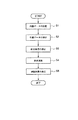
サーバ装置50は、この内部データ記憶部1の他に、外部データ記憶部2、外部DB接続情報記憶部3、結合履歴記憶部4、結合データ記憶部5を有し、さらに、第1の指定部6、呈示部7、第2の指定部8、外部データ取得部9、検索条件入力部10、結合演算部11、結合データ出力部12,検索部13を有する。以下、図11に示すフローチャートを参照して、図1のサーバ装置50の各構成部について説明する。
【0045】
まず、ステップS1において、第1の指定部6から内部データ記憶部1に記憶された内部データを指定する。第1の指定部6は、内部データ記憶部1に記憶されたデータのうち、所望のクラスのコンテンツデータを指定したり、内部データ記憶部1から所望のコンテンツデータのテーブルを検索するための検索条件などを入力するためのものである。検索条件としては、所望の分類項目や属性の値、キーワードなどである。
【0046】
検索部13は、第1の指定部6から入力された検索条件などを基に、内部データ記憶部1からコンテンツデータを検索する。例えば、上記検索条件にマッチしたクラスを検索して、当該クラスに登録されているコンテンツデータ(ここでは、テーブル形式で登録されているとする)を読み出して呈示部7へ渡す。
【0047】
呈示部7は、検索部13で検索されたコンテンツデータを、例えば、予め定められた数(例えば、上記のように100個)以内のコンテンツデータのグループ単位にユーザに呈示する。呈示部7で現在ユーザに提示しているグループに含まれるコンテンツデータからなるテーブルが結合演算部11での結合演算の処理対象となる。
【0048】
次に、ステップS2において、第2の指定部8から外部データを指定する。第2の指定部8は、外部データベースとしての例えば、第1、第2の外部DB51、52に記憶されているデータ(ここでは、テーブル形式で記憶されているものとする)を指定するためのもので、ユーザは、呈示部7により呈示されたコンテンツデータに関連する外部データを指定する。
【0049】
外部DB接続情報記憶部3には、外部データ取得部9が外部データベース、例えば第1、第2の外部DB51、52に接続するために必要なURLなどの接続情報が記憶されている。外部DB接続情報記憶部3には、例えば、図10に示すように、第1、第2の外部DB51,52のそれぞれについて、そこに記憶されている情報の種別と、外部DBの識別子と接続情報(例えば、IP、ホスト名、ポート番号、また当該接続先データベースに存在する結合演算を行うテーブル名など)がテーブル形式で記憶されている。
【0050】
外部データ取得部9は、この外部DB接続情報記憶部3に記憶された図10に示したようなテーブルを参照して、外部データベースにネットワークを介して接続し、外部データの辞書データを取得する。外部データ取得部9で取得された外部データの辞書データは、外部データ記憶部2に記憶される。なお、第2の指定部8で指定された外部データの辞書データが、既に外部データ記憶部2に記憶されているときには、外部DBのスキーマ変更などが発生した場合等、再取得が必要な場合を除き、外部データベースにアクセスすることはない。なお、外部データの辞書データとは、外部DBに存在するテーブル名および、そのテーブルを構成する属性項目名及びデータ型、キー情報を表す。外部DBが階層型データベースの場合には、階層関係、分類項目名、分類項目識別子、属性項目識別子、テーブル識別子なども含む。
【0051】
外部データ記憶部2は、外部データを記憶するための階層型データベースである。外部データを外部データ記憶部2に記憶する際には、外部データ処理部14は、外部データの辞書データにクラスを付与し、外部データ中の各項目(あるいは属性)にBSUのような一意な属性識別子を付与するとともに、各項目の値(あるいは属性値)のデータ型を判定する。
【0052】
第2の指定部8は、外部データ記憶部2から、指定された外部データを読み出すと、これを結合条件入力部10へ渡す。
【0053】
次に、ステップS3において、呈示部7で呈示された内部データのテーブル(ここでは、第1のテーブルと呼ぶ)と、第2の指定部8で指定した外部データのテーブル(ここでは、第2のテーブルと呼ぶ)を結合するための結合条件を設定する。
【0054】
結合条件入力部10は、上記2つのテーブルを結合するための結合条件を入力するために、結合条件入力画面をユーザ端末TEやサーバ装置50のディスプレイ装置などに表示するものである。このため結合条件入力部10は、第2のテーブル中の各項目(あるいは各属性)や、第1のテーブル中の各属性を表示するとともに、第2のテーブル中の各項目名(あるいは各属性名)と、第1のテーブル中の各属性名とを照合し、両者が一致する場合には、両者を対応付けてユーザ端末TEやサーバ装置50のディスプレイ装置に表示する。また、結合条件入力部10により入力された結合条件により結合演算を行う内部データのテーブルと、外部データのテーブルと、両者を結合する際に用いた結合条件を含む履歴情報(結合履歴)を結合履歴記憶部4に記憶する。ステップS4では、結合実行の指示が入力されると(例えば、図18の「結合実行」ボタンB106がユーザにより選択されると)、呈示部7で現在呈示されている、結合演算の処理対象である一定数のコンテンツデータからなる第1のテーブルと、第2の指定部8で指定した外部データのテーブル、すなわち、第2のテーブルとを、結合条件入力部10で入力された結合条件を用いて結合する。
【0055】
結合演算部11は、結合条件入力部10で入力された結合条件を基に、第1のテーブルと第2のテーブルとの間で結合演算を行う。この結合演算は、リレーショナルデータベースにおいてよく用いられる結合演算(JOIN)と同様である。
【0056】
次に、図12に示すフローチャートを参照して、図11のステップS1の処理動作についてより詳細に説明する。
【0057】
第1の指定部6は、例えば、図13に示すように、階層型データベース1に記憶されている階層構造を表すツリー(ユーザ端末TEやサーバ装置50のディスプレイ装置に)を表示する。例えば、ツリーから分類項目(クラス)「ノートPC」を選択すると、当該分類項目に登録されているコンテンツデータのテーブルの一覧1301が表示される。このテーブルの一覧1301から、所望のテーブル(例えば、TB01)をユーザが選択し(例えば、チェックボックスにチェックを入力し)、更にユーザが「コンテンツ表示」ボタン「B11」を選択すると(ステップS101)、検索部13は、内部データ記憶部1から、当該選択したテーブルに含まれている属性のうち、選択可能な属性を取出す。提示部7は、例えば、図14に示すような当該選択可能な属性のリストを表示する。図14に示したリストからユーザは、所望の属性を選択する(ステップS102)。この例では図14に示すように、テーブルTB01に登録されているコンテンツデータのもつ属性のうちチェックボックスにチェックの入った属性がユーザにより選択された属性である。次に、このリストの表示画面上に設けられている「OK」ボタンB14をユーザが選択すると、検索部13は、内部データ記憶部1から、テーブルTB01のステップS102で選択された属性に対応する部分のみ(図15参照)を読み出し、呈示部7に渡す。呈示部7は、図15に示すテーブル中のコンテンツデータを予め定められた所定数(たとえば、ここでは100個)以内のコンテンツデータからなるグループに分け(ステップS103)、先頭のグループに含まれるコンテンツデータを表すテーブルを図8に示したように表示する(ステップS104)。この呈示されたコンテンツデータのテーブル(第1のテーブル)を、結合演算の処理対象とする。また、必要があれば、この第1のテーブル上のコンテンツデータのうち、さらに、図9に示すように、ユーザにより選択されたコンテンツデータ(行)のみを結合演算の処理対象として選択する(ステップS105)。
【0058】
次に、図16に示すフローチャートを参照して、図11のステップS2の処理動作について更に詳細に説明する。
【0059】
図9に示すような第1のテーブルのコンテンツデータを表示する画面に設けられた「結合演算の実行」ボタンB1をユーザが選択することにより、第1の指定部6は、当該システム内の内部データ記憶部1に記憶されている内部データの辞書データを読み出すとともに、第2の指定部8は、外部データ記憶部2に記憶されている外部データを読み出し、図18に示すような階層化された分類項目およびコンテンツデータを上記画面に表示する。図18のラジオボタンB107は、分類項目を識別子(BSU)で表示するか、名称で表示するかを選択するためのものである。また、ボタンB108のような、分類項目やコンテンツデータ名称(テーブル名称)、結合条件名称などを検索するための画面を呼び出し、ユーザのテーブル選択、検索条件選択を助けるための図18に示すボタンB108を設けてもよい。さらに、ボタンB101により、ツリー上に内部データの表示に加えて、外部データの表示/非表示を切り替えることができてもよい。
【0060】
図19および図20は、結合演算相手のデータを内部データおよび外部データの2つのツリーに分離して表示する例である。例えば、図19でタブB109がユーザにより選択されると、呈示部7は、外部データの画面(図20)に切り替える。このようにして、画面を分けることにより、これから結合演算を行う相手テーブルが、内部データか外部データかをより明確にユーザに提示することができる。
【0061】
例えば、図18に示すような画面から外部データを表示する際には、外部データ取得部9は、外部DB接続情報記憶部3に記録されている接続情報に対応する外部データ(辞書データを含む)が既に外部データ記憶部2に記憶されているか検索する。外部データ記憶部2に当該外部データが記憶されており(ステップS111〜ステップS112)、且つ外部データを外部DBのスキーマ変更等の理由により、外部DBから再取得する必要がある場合には(ステップS113)、外部DBに接続して外部データを更新する。
【0062】
また、外部データ記憶部2に当該外部データが記憶されており(ステップS112)、且つ外部DBを再取得する必要がない場合には(ステップS113)、外部データ記憶部に保存されている外部データを利用する。
【0063】
一方、外部データ記憶部2に、当該外部データが記憶されていないときには(ステップS112)、外部DB接続情報記憶部3に記憶されている接続情報を参照し、当該接続情報に記載されている外部データベースが存在するか否かを調べる。この調べた結果、存在するときには(ステップS114)、当該外部データベースの接続情報を用いて当該外部データベースにアクセスして、外部データを取得する(ステップS115)。
【0064】
外部データベースから取得した外部データは、外部データ記憶部2に格納するが、この際、当該外部データは、階層構造をもたない場合(ステップS116)、内部データ記憶部1に記憶されている階層構造を模した階層構造に従って記憶される(ステップS117〜ステップS119)。
【0065】
例えば、第1の外部DB51には、図4に示した階層構造(スキーマデータ)と、当該階層構造を構成する項目に登録されているテーブルが記憶されているが、これらが外部データ取得部9により取得されるとする。すると、外部データ処理部14は、外部データにクラス(クラス識別子)を付与し(ステップS117)、外部データ中の各項目(あるいは属性名)にシステム内で一意な属性識別子を付与するとともに(ステップS118)、各項目の値(あるいは属性値)のデータ型を判定して、当該項目あるいは属性に付与する(ステップS119)。
【0066】
この結果、ステップS120では、図20に示すように、内部データ記憶部1に記憶されている木構造と同様に外部データを記憶するようになっている。すなわち、第1の外部DB51や第2の外部DB52に格納されている外部データに対応するような階層構造を格納する。
【0067】
例えば、階層構造をもつ第1の外部DB51に記憶されている外部データを外部データ記憶部2に格納する場合には、ノード401に、当該外部データの階層構造を移植する形で格納する。この際、当該外部データの階層構造を構成する各クラスのもつ属性には、BSUのような一意な属性識別子を付与するとともに、当該外部データのスキーマデータで定義されている各属性値のデータ型を取得して記憶する。 また、第2の外部DB52に記憶されているテーブル形式の外部データを外部データ記憶部2に格納する場合には、ノード402に、当該テーブル登録する。この際、ノード402に対応するクラスに当該外部データのもつ項目を属性としてもたせ、各属性にBSUのような一意な属性識別子を付与するとともに、各属性値のデータ型を取得して記憶する。
【0068】
なお、ステップS123で、ユーザが指定した種別のデータを記憶する外部データベースに関する情報が外部DB接続情報記憶部3に記憶されておらず、新たな外部データベースを追加するときには、直接外部データベースを指定するようにしてもよい(ステップ125)。例えば、図18に示すような「外部DB情報の追加/編集」ボタンB105を押すと、図21に示すような外部データベースに関する情報を入力するための入力画面が表示され、この画面上で、所望の外部データベースの識別子や、IPやホスト名などの接続情報、テーブル名称やテーブルタイプなどのテーブル情報などを入力すると、外部DB接続情報記憶部3に記憶される(ステップS125)。この後、外部データ取得部9は、当該情報を用いて、当該所望の外部DBへアクセスし、外部データを取得する、前述同様にして、取得した外部データを外部データ記憶部2へ記憶する(ステップS114〜ステップS120)。
【0069】
第2の指定部8は、外部データ記憶部2から外部データを読み出し、例えば、図18に示すような画面を表示する(ステップS122)。図18に示した画面には、当該システム内で取り扱うすべての辞書ツリー(階層構造に模した外部データも含む)のルートノード300「universal root」を設け、その子ノードとして、内部データの全ての辞書ツリーの親ノードであるノード301「internal database」を設け、その子ノードとして、内部データから取得した階層木(辞書ツリー)を表示する。第1の外部DB51および第2の外部DB52から取得した外部データに対応する辞書ツリーは、ノード300の子ノード302「external database」の子ノードとして、それぞれ、ノード303「ex_database01」、ノード304「ex_database02」として表示されている。当該部分木を構成する分類項目のいずれかに登録されているコンテンツデータのテーブルの識別子(ここでは、例えば、table01、table101など)を選択することで、所望のテーブルを選択する(ステップS124)。このようにして選択されたテーブルが第2のテーブルである。
【0070】
次に、図17に示すフローチャートを参照して、図11のステップS3の処理動作について更に詳細に説明する。例えば、図18のボタンB102が押され新規結合条件の作成が要求された場合(ステップS131)、結合条件入力部10は、第1のテーブル中の各属性名と、第2のテーブル中の各項目名(属性名)とを照合して、第1のテーブル中の属性と同じ名称あるいは識別子の項目(属性)を第2のテーブル中の項目(属性)から探す(ステップS132)。そして、第1のテーブル中の各属性と、第2のテーブル中の各項目(各属性)を表示するとともに、名称あるいは識別子が同じである属性と項目(属性)はそれらの対応が明らかになるように例えば、図22に示すような画面を表示する(ステップS133)。
【0071】
図22では、内部データのテーブルがTB01であり、外部データのテーブルが、第2の外部DB51に記憶されているテーブルtable01である場合を示している。この場合、テーブルtable01中の項目は、「製品コード」、「在庫数」、「入荷予定日」といった項目があるが、このうち、「製品コード」は、第1のテーブルであるテーブルTB01にも存在する。そこで、図22では、第2のテーブル中の「製品コード」を、第1のテーブル中の「製品コード」とを同じ行で表示している。これらは属性の識別子(BSU)が同じであることにより、同じ属性とみなしている。
【0072】
これにより、ユーザは面倒な結合条件を自分で設定することなく、用意されている候補の中から選択し設定することができる。階層型データベースでは、上位クラスの属性を下位クラスで継承するという特徴をもっているため、上位クラスで登録されている結合条件は、通常、下位クラスにも当てはまる。ツリー上に表示することにより、結合条件として登録されているクラスそのものだけではなく、その下位に位置するクラスに対しても、同じ結合条件を用いて結合する相手表として容易に選択することが可能となる。
【0073】
通常のリレーショナルデータベースにおける表の間で、属性名称が一致、尚且つデータ型が一致していても、属性の一致の完全な保証は行われない。しかしながら、本システムにおける階層型データベースにおいては、属性が一意な識別子(BSU)によって管理されていること、また上位階層で定義した識別子をもった属性(プロパティ)を下位階層で継承しているため、その属性が定義されているクラスより下位のクラスにおいては、一致した属性を持つことが保証されている。これを利用し、図22に示す画面では、結合を行うための属性に、表の間で一致している属性をデフォルトでユーザに提示し、ユーザが結合条件をより容易に記述できるような入力補助を行うことが可能である。
【0074】
図22に示した画面上に表示された、第1のテーブルと第2のテーブルとの間で一致する項目名、属性名から、結合条件として用いるものを選択する(ステップS133)。例えば、図22では、第1のテーブル中の属性「製品コード」と第2のテーブル中の属性「製品コード」とが一致しているので、これを結合条件として指定する場合には、ユーザは「詳細条件」ボタンB23を押す。
【0075】
あるいは、図23のように、第1のテーブルの属性と、同一とすべき且つ、データ型等を考慮した場合でも同一とすることが可能な第2のテーブル中の項目(属性)の候補をプルダウンメニューで表示し、ユーザが個々に設定することも可能である(ステップS134)。必要であれば、結合のためにマッピングした各属性に対して、属性の結合条件の入力を行ってもよい(ステップS135)。通常は、属性の値が一致するものを結合する(等価結合)。
【0076】
さらに、必要であれば、結合タイプを選択することも可能である(ステップS136)。本実施形態では、第1のテーブルを起点として考えているため、通常の結合演算では、左外部結合を既定値として設定することを想定しているが、例えば、図22に示す画面上で「結合タイプの設定」ボタンB24を選択すると、図24に示すような画面が表示され、結合のタイプを選択することも可能である。この画面上で、第1のテーブルに第2のテーブルを結合する際に、どのように結合するかを設定する。例えば、図24に示す例では、第1のテーブルを右におき、第2のテーブルと外部結合を行うという内容の設定がなされている。
【0077】
さらに、第1のテーブル中の複数の属性と第2のテーブル中の複数の属性のうち、結合演算の対象となる属性を選択するようにしてもよい(ステップS137)。例えば、図22に示す画面上で、結合演算の対象とする属性に対応する「表示」項目欄にユーザがチェックを入力する。これにより、結合演算時のデータ数をさらに低減することができる。このようにして作成された結合条件は、図22の「確定」ボタンB21を選択すると、この画面上での設定内容を保存するか否かを問い合わせるメッセージが表示される(ステップS138)。ユーザが「保存する」を選択したときには、当該画面上での設定内容に、名前をつけ、結合履歴として結合履歴記憶部4に記憶される(ステップS139)。
【0078】
さらに、結合履歴から結合条件を選択し、再利用することもできる。すなわち、図18に表示されている第2のテーブルに対して保存されている結合条件(ここでは、例えば、結合条件01、結合条件02など)を選択された状態で、ボタンB103が押される(ステップS140)と、結合条件入力部10は、結合履歴記憶部4に記憶されている図25に示したような結合履歴から、選択された結合条件を読み出し、これを表示する(ステップS141)。
【0079】
結合履歴記憶部4は、過去に結合演算を行った際に用いた結合条件を結合履歴として記憶するためのもので、各結合条件を、当該結合履歴(結合条件)を識別するための識別情報と、当該結合条件の名称、当該結合条件を適用した第1のテーブルと第2のテーブル、当該結合条件を適用して結合演算を行った結果得られるデータのうち表示対象として指定された属性、あるいは、結合演算対象として指定された属性とその条件、結合タイプなどが記録されている。
【0080】
ユーザは、表示された結合条件をそのまま今回の結合条件として用いることもできる。表示された結合条件を変更するか、あるいは、再利用して新規の結合条件を作成する場合には(ステップS142)、前述と同様に、結合条件入力作業を行う(ステップS134〜S137)。このようにして編集した結合条件は、ユーザにより図22に示すボタンB21が押されると、同様に名前を付けて結合履歴記憶部4に記憶される。
【0081】
またこのようにして、結合履歴記憶部4に記憶された結合条件は、ユーザにより図18に示すボタンB104が押される(ステップS143)ことにより、削除することも可能である(ステップS144)。図11のステップS4において、第1のテーブルと第2のテーブルとの間の結合演算の実行指示が入力されると、結合演算部11は、両テーブルの結合演算を実行する。すなわち、結合条件入力部10で入力された結合条件や結合タイプを基に、呈示部17で現在呈示されている一定数(例えば、ここでは100個)のコンテンツデータのテーブル(第1のテーブル)と、外部データのテーブル(第2のテーブル)との間で結合演算を行う。
【0082】
結合演算は、図7で説明したように、両テーブルについて、検索条件として指定された属性や項目に対応する値をサーチし、第1のテーブル上のレコードデータと第2のテーブル上のレコードデータのうち、検索条件として指定された属性や項目に対応する値が双方とも同じであるレコードデータ間を結合して、たとえば、図7(d)や図7(e)に示すような結合テーブルを作成する。
【0083】
結合演算部11は、結合演算の結果得られた新たなテーブルを結合データ記憶部5に記憶するとともに、結合データ出力部12へ出力する。結合データ出力部12は、受け取った結合データを要求元のユーザ端末TEに送信したり、サーバ装置50のディスプレイ装置などに表示する。要求元のユーザ端末TEは、受信した結合データを、所定のディスプレイに表示する。
【0084】
以上説明したように、上記第1の実施形態によれば、内部データを記憶する階層型データベースから所望のクラスのコンテンツデータを予め定められた所定数以内のコンテンツデータからなる複数のグループに分け、このグループ単位で表示するとともに、このグループ単位で他のレコードデータのテーブルと結合するため、結合演算対象のデータ数が削減される。この結果、結合演算処理の負荷が少なくなる。グループ内のコンテンツデータのうち、ユーザにより選択されたコンテンツデータを結合演算処理の対象とすることで、処理対象のデータ数をより削減することができる。
【0085】
内部データを記憶する階層型データベースとは異なる分類体系、階層構造の外部データベースから取得する外部データも、内部データを記憶する階層型データベースの階層構造の一部として記憶することにより、図18に示すように、内部データのテーブルと結合させる他方のクラスあるいはテーブルをGUI上で表示されたツリー上で選択することができる。
【0086】
内部データのテーブル(上記第1のテーブル)上の属性項目のうち、外部データのテーブル(上記第2のテーブル)上の属性項目のいずれかと同じ名称あるいは識別子をもつ属性項目を求めて、例えば、図22に示すように、当該同じ名称あるいは識別子をもつ属性項目の一覧を表示することにより、第1のテーブルと第2のテーブルとの間で結合演算を行う際に用いる結合条件を容易に設定することができる。
【0087】
なお、図22に示すような、テーブルの属性項目の一覧の表示された結合条件設定画面をクラス・オペレーション・ページと呼ぶ。
【0088】
結合演算に用いた結合条件を結合履歴として記憶しておき、これを、これから行う結合演算で用いる結合条件を入力(設定)する際に用いることにより、結合条件を容易に設定することができる。
【0089】
なお、結合演算(JOIN)の対象となるクラスの演算の順番を指定し、この演算の順番を保存しておいて、GUI上からユーザが選択して現在表示しているクラスについて既に登録された結合条件を読み出して結合演算を行うようにしてもよい。
【0090】
また、結合演算(JOIN)の対象となるクラスの演算の順番を指定し、この演算の順番を保存しておいて、その演算対象となりうる全てのクラスついて、GUI上からユーザが選択して表示しているクラス、またはその上位クラスに関係する既に登録された結合条件を読み出し、これを結合演算に用いるようにしてもよい。結合演算(JOIN)において、結合テーブルの順番を指定することにより、演算処理時間の短縮に有効であることが知られている。従って、結合順番を記憶しておくことは、演算処理時間を短縮するために非常に重要である。
【0091】
さらに、結合演算(JOIN)の対象となる他のクラスとの間に、全く同一の名称あるいは識別子を持つ属性がない場合でも、属性値のデータ型が同一であるならば同一の属性であるとみなし、これらを対応付けて図22に示したようにユーザに呈示するようにしてもよい。
【0092】
(第2の実施形態)
上記第1の実施形態では、内部データのテーブル(第1のテーブル)を外部データのテーブル(第2のテーブル)とを結合する場合について説明したが、同様の手法が内部データの2つのテーブル間を結合する場合についても適用可能である。第1の実施形態と異なる部分についてのみ説明する。
【0093】
以下、図26に示すフローチャートを参照して説明する。
【0094】
まず、ステップS201では、図12のフローチャートに示したように、第1の指定部6において、内部データ記憶部1から、所望のコンテンツデータのテーブルを指定する。すなわち、ステップ201では、内部データ記憶部1に記憶されている階層構造を構成する分類項目(クラス)のうちの1つ(ここでは、第1の分類項目と呼ぶ)を指定し、当該分類項目に登録されているコンテンツデータのテーブルを選択する(ステップS101)。呈示部7は、当該テーブル中のコンテンツデータを予め定められた所定数(たとえば、ここでは100個)以内のコンテンツデータからなるグループに分け(ステップS102)、先頭のグループに含まれるコンテンツデータを表すテーブルを図8に示したように表示する(ステップS103)。この呈示されたコンテンツデータのテーブル(第1のテーブル)を、結合演算の処理対象とする。また、必要があれば、この第1のテーブル上のコンテンツデータのうち、さらに、図9に示すように、選択されたコンテンツデータ(行)のみを結合演算の処理対象として選択する(ステップS104)。ここまでがステップS201で行われる。 次に、上記ステップS201と同様にして、第1の指定部6で、内部データ記憶部1から、当該第1のテーブルに結合する第2のテーブルを指定する(ステップS202)。すなわち、ステップ202では、内部データ記憶部1に記憶されている階層構造を構成する分類項目(クラス)のうちの他の1つ(ここでは、第2の分類項目と呼ぶ)を指定し、当該分類項目に登録されているコンテンツデータのテーブルを選択する(ステップS101)。呈示部7は、当該テーブル中のコンテンツデータを予め定められた所定数(たとえば、ここでは100個)以内のコンテンツデータからなるグループに分け(ステップS102)、先頭のグループに含まれるコンテンツデータを表すテーブルを図8に示したように表示する(ステップS103)。この呈示されたコンテンツデータのテーブル(第2のテーブル)を、結合演算の処理対象とする。また、必要があれば、この第2のテーブル上のコンテンツデータのうち、さらに、図9に示すように、選択されたコンテンツデータ(行)のみを結合演算の処理対象として選択する(ステップS104)。ここまでがステップS202で行われる。
【0095】
次に、図17のフローチャートと同様にして、結合条件の設定を行う(ステップS203)。
【0096】
図26のステップS204において、第1のテーブルと第2のテーブルとの間の結合演算の実行指示が入力されると、結合演算部11は、両テーブルの結合演算を実行する。
【0097】
結合演算の結果得られた新たなテーブルは結合データ記憶部5に記憶するとともに、結合データ出力部12から要求元のユーザ端末TEやサーバ装置50のディスプレイ装置などに表示される(ステップS205)。
【0098】
(第3の実施形態)
なお、ここでは、上記第1の実施形態とは異なる部分についてのみ説明する。
【0099】
RDBテーブル間で結合演算(JOIN)を行う場合、2つのテーブル間で結合条件として指定する属性項目の値が、多対多で対応(たとえば一致)する場合、その対応する数が多いほど演算数が多くなる。したがって、演算数が少なくなるような結合演算を行うためには、できるだけ2つのテーブルで対応する値が少なくなるような属性項目を指定すればよい。
【0100】
テーブルのキー属性は、テーブルの中のレコードを一意に識別するためのものである。キー属性は、複数でも可能であり、複数の場合には、その組み合わせの値で一意にレコードを識別する。したがって、両テーブルのキー属性を、結合条件としてユーザに最初に提示して、結合条件としての選択を促すことにより、演算数を制御することが可能である。
【0101】
ここで、図27、図28を参照して説明する。
【0102】
図27は、マウスのコンテンツデータ例であり、図28はノートPCのコンテンツデータ例である。両者は、マウスの「インターフェース」とノートPCの「マウスインターフェース」を結合条件として結合することが可能である。結合条件を「マウス.インターフェース=ノートPC.マウスインターフェース」として結合演算を行った場合よりも、マウスのキー属性である「製品コード」を含んだ結合条件、「マウス.製品コード=ノートPC.推奨マウス製品コード」のほうが、処理時間が少なくて済む。
【0103】
すなわち、結合条件を「マウス.インターフェース=ノートPC.マウスインターフェース」として結合演算を行った場合には、例えば、図27のマウスのコンテンツデータのうち、製品コード「MR001」のコンテンツデータのインターフェースは「USB」であるので、図28のノートPCのコンテンツデータのうち、「USB」を属性「マウスイターフェース」の値としてもつ製品コード「Dyna100」「Dyna101」「Dyna102」「Dyna103」「Dyna104」の5つのコンテンツデータのそれぞれが、製品コード「MR001」のマウスのコンテンツデータと結合して、5つの結合されたコンテンツデータが生成される。図27のマウスのコンテンツデータのうち、製品コード「MR002」のコンテンツデータに対しても、同様にして、図28のノートPCのコンテンツデータのうち、製品コード「Dyna100」「Dyna101」「Dyna102」「Dyna103」「Dyna104」の5つのコンテンツデータのそれぞれが結合して、5つの結合されたコンテンツデータが生成される。図27のマウスのコンテンツデータのうち、製品コード「MR003」や「MIR002」のコンテンツデータに対しても、同様にして、それぞれ5つの結合されたコンテンツデータが生成される。
【0104】
これに対し、マウスのキー属性である「製品コード」と、ノードPCの属性「「推奨マウス製品コード」を用いた結合条件「マウス.製品コード=ノートPC.推奨マウス製品コード」で、結合演算を行った場合には、例えば、図27の製品コード「MR001」のマウスのコンテンツデータに対して、図28のノートPCのコンテンツデータのうち当該「MR001」を属性「推奨マウス製品コード」の値としてもつコンテンツデータは、製品コード「Dyna100」と「Dyna101」の2つのコンテンツデータであるので、これらを製品コード「MR001」のマウスのコンテンツデータにそれぞれを結合して、2つの結合されたコンテンツデータが生成される。また、図27の製品コード「MR002」のマウスのコンテンツデータに対して、図28のノートPCのコンテンツデータのうち当該「MR002」を属性「推奨マウス製品コード」の値としてもつコンテンツデータは、製品コード「Dyna102」と「Dyna103」の2つのコンテンツデータであるので、これらを製品コード「MR002」のマウスのコンテンツデータにそれぞれを結合して、2つの結合されたコンテンツデータが生成される。
【0105】
他のマウスのコンテンツデータに対しても同様で、1つのマウスのコンテンツデータに結合させるノートPCのコンテンツデータの数を小さくすることができる。このように、2つのテーブルを結合する際の結合条件として、各テーブル中で同じ値をもつコンテンツデータの数がより少ない(好ましくは、1つのみであるような)属性(例えば、各コンテンツデータのそれぞれを識別することができるような情報を値としてもつ、例えば「製品コード」のような属性(これをキー属性と呼ぶ))を用いることで、結合演算対象のデータ数を削減することができる。このように、結合条件入力部10は、外部データと内部データの2つのテーブルのそれぞれからキー属性を求めて、それらを図22に示すように、ユーザに提示する。図22では、第1のテーブル中の属性と第2のテーブル中の属性のうち、キー属性の属性に対しては、「キー」欄に「○」が表示されている。キー属性を結合条件として指定するように、ユーザに対して推奨することにより、結合演算数が少なくなるような結合条件の指定を行わせることができる。推奨の方法は、図22のように、結合条件入力画面を表示する際に、キー属性どうしをあらかじめ結合条件としてシステムが与える他、キー属性が結合条件として選ばれていない場合には、結合条件決定の際(例えば、図22では「OK」ボタンB21が押された際)、警告メッセージを出し、ユーザに結合条件として指定するように促すなども考えられる。
【0106】
また、結合条件としては、等結合(等価結合)のほか、非等価結合も入力可能である。例えば、第1のテーブル中のキー属性である「製品コード」と、当該属性に対応する第2のテーブル中の属性であって、当該第2のテーブル中のキー属性とからなる結合条件を指定する場合には、第1のテーブルの属性と第2のテーブルの属性を結合条件として指定したことによって、図22に示すアクティブになった「詳細条件」ボタンB23をユーザが押すことによって指定可能とすればよい。
【0107】
(第4の実施形態)
なお、ここでは、上記第1の実施形態とは異なる部分についてのみ説明する。
【0108】
階層構造を持つデータベースにおいては、上位の製品分類で定義された属性項目を下位の分類が継承する特性をもっている。したがって、ある製品分類で定義した結合条件(結合履歴)をその下位の分類において適応することが可能である。
【0109】
例えば、図2の「PC本体」ノード102に図29に示すようなテーブル「TB10」が登録され、「ノートPC」ノード105に図3に示したようなテーブル「TB01」が登録され、「デスクトップPC」ノード106に図30に示すようなテーブル「TB11」が登録されているとする。図29に示すテーブル「TB10」はスキーマのみが定義されたテーブルであるが、コンテンツデータが登録されていても構わない。
【0110】
また、第1の外部DB51に構成されている階層型データベースの階層構造の一部を概略的に示した図4において、「PC本体在庫」ノードに図31に示すようなテーブル「table00」が登録され、「ノートPC在庫」ノードに図5に示したようなテーブル「table01」が登録され、「デスクトップPC在庫」ノードに図32に示すようなテーブル「table02」が登録されているとする。図31の「table00」は、スキーマのみが定義されたテーブルであるが、コンテンツデータが登録されていても構わない。
【0111】
図2の「PC本体」ノード102のテーブル「TB10」と、図4の「PC本体在庫」ノードのテーブル「table00」を結合演算して、PCの在庫を求めるための、結合条件(履歴)を登録しておく。結合条件は、図25の「結合条件003:在庫チェックテンプレート」とする。すなわち、結合条件は、「TB10」の属性「PRP003:製品コード」に対応する値と、「table00」の属性「PRP003:製品コード」に対応する値が同じであるものを結合(JOIN)し、(「表示プロパティ」の欄で指定されている)属性「PRP003:製品コード」と「PRP101:在庫数」について、その値を表示するというものである。
【0112】
例えば、図33に示すような外部データと結合条件の選択画面において、「継承結合条件の表示」ボタンB30をユーザが選択すると、承継結合条件「結合条件003:在庫チェックテンプレート」が表示される。この結合条件は、テーブル「TB10」とテーブル「table00」を結合する際に用いる結合条件であるから、結合条件003:在庫チェックテンプレート」で用いる属性は、テーブル「TB10」とテーブル「table00」のそれぞれの分類項目の下位分類に継承されている。すなわち、テーブル「table00」の登録されている図4の「PC本体在庫」ノードの子ノードである「ノートPC在庫」ノードに登録されているテーブル「table01」と、テーブル「TB10」の登録されている図2の「PC本体」ノード102の子ノードである「ノートPC」ノード105に登録されているテーブル「TB01」とを結合する際に用いる結合条件としても利用できるため、図33では、テーブル「table01」の結合条件としても表示される。
【0113】
このように、上位の分類で行ったテーブル間の結合演算で用いた結合条件を利用することにより、より効率的に結合演算を行うための条件入力が簡単となる。
【0114】
上位から継承した結合条件を利用する際の手順を説明する。まず、図11のステップS1におて、図13に示すような画面上で内部データのテーブル(第1のテーブル)を指定した後(例えば、テーブル「TB01」を指定する)、ステップS2では、図33に示すような画面上で、外部データのテーブル(第2のテーブル)を指定する(例えば、テーブル「table01」を指定する)。ステップS3では、結合条件を設定する。図17のステップS140〜ステップS141の処理動作が、図34に示す処理動作に対応する。
【0115】
図33に示す画面上のボタン30をユーザが選択すると(図34のステップS151)、第2の指定部8は、結合履歴記憶部4に記憶されている結合履歴から、上記第1のテーブルが属するクラスあるいは上位クラスに登録されているテーブルと、上記第2のテーブルが属するクラスあるいは上位クラスに登録されているテーブルとを結合する際に用いた結合条件(ここでは、例えば、「結合条件003:在庫チェックテンプレート」)を読み出し、これを図33に示すように表示する(図34のステップS152)。
【0116】
(まとめ)
以上説明したように、上記第1〜第4の実施形態によれば、階層型データベースに登録されているコンテンツデータのテーブルと他のテーブルとの結合演算の演算処理数を削減するとともに、結合演算条件の入力が容易に行える。
【0117】
本発明の実施の形態に記載した本発明の手法は、コンピュータに実行させることのできるプログラムとして、磁気ディスク(フレキシブルディスク、ハードディスクなど)、光ディスク(CD−ROM、DVDなど)、半導体メモリなどの記録媒体に格納して頒布することもできる。
【0118】
なお、本発明は上記実施形態そのままに限定されるものではなく、実施段階ではその要旨を逸脱しない範囲で構成要素を変形して具体化できる。また、上記実施形態に開示されている複数の構成要素の適宜な組み合わせにより、種々の発明を形成できる。例えば、実施形態に示される全構成要素から幾つかの構成要素を削除してもよい。さらに、異なる実施形態にわたる構成要素を適宜組み合わせてもよい。
【0119】
【発明の効果】
以上説明したように、本発明によれば、階層型データベースに記憶されているコンテンツデータのテーブルと他のテーブルとの結合演算の演算処理数を制御し、簡単に結合演算条件の入力が行えるGUIを提供することができる。
【図面の簡単な説明】
【図1】 本発明の実施形態にかかるシステム全体の構成例を示した図。
【図2】 内部データ記憶部1に構成されている階層型データベースの階層構造を概略的に示した図。
【図3】 階層型データベースに登録されているコンテンツデータの具体例を示した図。
【図4】 第1の外部DBに格納されている階層構造の一部を概略的に示した図。
【図5】 図4に示した階層型データベースに登録されているコンテンツデータの具体例を示した図。
【図6】 第2の外部DBに登録されているテーブルの一例を示した図。
【図7】 サーバ装置の処理動作の概略を説明するための図。
【図8】 コンテンツデータのテーブルの表示例を示した図。
【図9】 コンテンツデータのテーブルの表示例を示した図。
【図10】 外部DB接続情報記憶部に記憶されている情報の一例を示した図。
【図11】 サーバ装置の処理動作の概略を説明するためのフローチャート。
【図12】 内部データを指定するための処理動作を説明するためのフローチャート。
【図13】 内部データを指定するための画面の一例を示した図。
【図14】 指定された内部テータのもつ複数の属性から所望の属性を選択するための画面の一例を示した図。
【図15】 指定された内部データのテーブルの一表示例を示した図。
【図16】 外部データを指定するための処理動作を説明するためのフローチャート。
【図17】 結合条件を設定するための処理動作を説明するためのフローチャート。
【図18】 外部データを指定するための画面の一例を示した図。
【図19】 内部データを指定するための画面の一例を示した図。
【図20】 外部データを指定するための画面の他の例を示した図。
【図21】 外部データベースに関する情報を入力するための入力画面の一例を示した図。
【図22】 結合条件入力画面の一例を示した図。
【図23】 結合条件入力画面の一例を示した図。
【図24】 結合タイプの設定画面の一例を示した図。
【図25】 結合履歴の一例を示した図。
【図26】 本発明の第2の実施形態にかかるサーバ装置の処理動作を説明するためのフローチャート。
【図27】 結合演算対象のテーブルの(マウスのコンテンツデータのテーブル)の一例を示した図。
【図28】 結合演算対象のテーブルの(ノートPCのコンテンツデータのテーブル)の一例を示した図。
【図29】 図2の「PC本体」ノードに登録されているテーブル「TB10」の一例を示した図。
【図30】 図2の「デスクトップPC」ノードに登録されているテーブル「TB11」の一例を示した図。
【図31】 図4の「PC本体在庫」ノードに登録されているテーブル「table00」の一例を示した図。
【図32】 図4の「デスクトップPC在庫」ノードに登録されているテーブル「table02」の一例を示した図。
【図33】 外部データと結合条件の選択画面の一表示例を示した図。
【図34】 上位から継承した結合条件を利用する際の処理手順を説明するためのフローチャート。
【符号の説明】
1…内部データ記憶部、2…外部データ記憶部、3…外部DB接続情報記憶部、4…結合履歴記憶部、5…結合データ記憶部、6…第1の指定部、7…呈示部、8…第2の指定部、9…外部データ取得部、10…結合条件入力部、11…結合演算部、12…結合データ出力部、13…検索部、14…外部データ処理部、51…第1の外部データベース、52…第2の外部データベース、TE…ユーザ端末。[0001]
BACKGROUND OF THE INVENTION
The present invention relates to a hierarchical database.
[0002]
[Prior art]
In a database having a hierarchical structure in which the lower level inherits the attributes of the upper classification, such as an object-oriented database (OODB) or an object relational database (ORDB), the attribute has a structure in which the attributes are increased in the lower classification according to inheritance. Inheriting this higher-order attribute to the lower-order is usually called “inheritance” (for example, see Non-Patent Document 1).
[0003]
In the literature of object-oriented databases, classification in a hierarchy is often called “class”. On the other hand, in an object-relational database (ORDB), this is equivalent to a table that allows inheritance, and the attributes from the upper table to the lower table, that is, the columns constituting the upper table, between tables having a hierarchical relationship. Header information is inherited to the lower table. Here, both are referred to as a “hierarchical database”. Data having the same attribute type belonging to the classification of each hierarchy is called “instance” or “content data”, and the set is called “population” of data.
[0004]
There is ISO13584 (Parts Library) as an international standard for implementing an electronic catalog system that electronically provides product information on the Internet. This is also one of hierarchical databases. ISO13584 aims to share and reuse product information by composing an electronic catalog with a schema and content and providing a unified data structure.
[0005]
In the schema defined by ISO13584, the product classification is a hierarchical representation of “product class” in a single tree structure. Each “product class” has an “attribute item”, and an “attribute item” of a certain “product class” is inherited by a lower “product class”. The “product class” and the “attribute item” are each assigned a unique ID called “BSU code” so that they can be uniquely specified. On the other hand, the content portion is expressed as a table in which attribute values specific to each product are embedded in attribute items defined in this schema.
[0006]
While ISO13584 provides a framework as an electronic catalog, international standardization of actual schemas is also underway. In IEC61360, the upper hierarchy of schemas in the electric / electronic field, that is, “product class” and “ It promotes standardization of general parts for “attribute items”. As a result, the product catalog creators of each company can determine their own detailed “product class” and “attribute item” as a subordinate development from IEC61360, and create their own content. Electronic catalog users can search the desired products by following the classification hierarchy of “product class” and narrowing down the necessary products by referring to attribute values. Become. In recent years, following these trends, several systems based on ISO13584 have been developed.
[0007]
In relational databases and ORDB, a join operation (JOIN) is prepared as one of operations between tables, but this operation is also possible in a hierarchical database. In general, a join operation (JOIN) is a simple but time-consuming operation in which a loop of the number of rows × the number of rows is generated. The number of operations cannot be controlled, the number of processing operations is enormous, and a join operation (JOIN) that imposes a load on the system may occur.
[0008]
[Non-Patent Document 1]
Object-Oriented Concepts, Databases, and Applications, Edited by Won Kim, 1989, ACM Press
[0009]
[Problems to be solved by the invention]
As described above, conventionally, in a hierarchical database having a hierarchical structure in which a plurality of classification items are hierarchically related, the content data table registered in the classification items constituting the hierarchical structure is stored in the same or another database. When the tables are joined, there is a problem that a join operation (JOIN) that places a load on the system occurs because the number of computation processes is not controlled.
[0010]
Therefore, in view of the above problems, the present invention controls the number of processing operations of a join operation between a table of content data stored in a hierarchical database and another table, and assists the condition input of the join operation. It is an object to provide a data processing apparatus and method.
[0011]
[Means for Solving the Problems]
The present invention has (a) a hierarchical structure in which a plurality of classification items are hierarchically related, and each classification item has an attribute including an attribute of a classification item in a higher hierarchy of the classification item. Is registered in the selected first category item among the plurality of category items from the first database in which a plurality of content data composed of values corresponding to the attributes of the category item are registered. (B) dividing the plurality of content data acquired in the first step into a plurality of groups consisting of a predetermined number of content data, Display a first table of content data included in one selected group, and (c) each with a value corresponding to each of a plurality of items The second table is obtained from storage means for storing a first table of a plurality of record data to be formed, and (d) a first attribute that is one of a plurality of attributes of the first classification item And a first item that is one of the plurality of items, and (e) content data in the first table and the plurality of record data in the second table, Content data and record data in which the value corresponding to the first attribute and the value corresponding to the first item match are combined, respectively, and the attribute of the first classification item and the plural A third table representing a plurality of combined data composed of values corresponding to the respective items is generated. According to the present invention, it is possible to shorten the processing time of the join operation by narrowing down the number of content data to be subjected to the join operation.
[0012]
Further, an attribute having the same name or identifier as any one of the plurality of items is obtained from the plurality of attributes of the first classification item, and a list of attributes and items having the same name or identifier is obtained. By displaying and specifying (as a join condition) the first attribute and the first item from the list, it is possible to easily designate a join condition necessary for a join operation.
[0013]
DETAILED DESCRIPTION OF THE INVENTION
Embodiments of the present invention will be described below with reference to the drawings.
[0014]
(First embodiment)
FIG. 1 shows a configuration example of the entire system according to the present embodiment. For example, a
[0015]
The first and second
[0016]
Data (external data) stored in the first
[0017]
The internal
[0018]
The hierarchical database has a hierarchical structure in which a plurality of classification items are hierarchically related, and each classification item has attributes including attributes of a classification item in a higher hierarchy of the classification item. Content data having attributes included in the set of attributes is registered.
[0019]
Information relating to each hierarchical structure such as the parent-child relationship between the classification items and the classification items constituting the hierarchical structure and the attributes of the classification items, that is, schema data and information relating to the attributes of the classification items are dictionary data.
[0020]
The internal
[0021]
In the content
[0022]
FIG. 2 schematically shows the hierarchical structure of the hierarchical database configured in the internal
[0023]
In other words, “electronic parts” are subdivided into two classification items “PC main body” and “peripheral equipment”, and “PC main body” is subdivided into two classification items “notebook PC” and “desktop PC”. , “Peripheral device” indicates that it is subdivided into three classification items of “memory”, “resistor”, and “mouse”.
[0024]
Each hierarchically related classification item (also referred to as a class) has a unique attribute (portion surrounded by a dotted line). Each classification item inherits the attribute of the classification item in the upper hierarchy of the classification item in the hierarchical structure. For example, the “notebook PC” attribute of the
[0025]
Such a data model is basically the same as that used in ISO13584 / Parts Library (PLIB), which is an international standard for parts library exchange format. In PLIB, as a code system for identifying each classification and attribute, a BSU code (attribute identifier) guaranteed to be a unique code in the world is used separately from the name. However, for simplicity of explanation, Japanese names are used for classification names and attribute names. However, this limitation does not prevent application of the present invention to PLIB.
[0026]
Each classification item shown in FIG. 2 is composed of values corresponding to the attributes of the classification item (attributes unique to the classification item and attributes inherited from the classification item at a higher hierarchy of the classification item). Content data is registered.
[0027]
FIG. 3 shows a specific example of content data registered in the hierarchical database shown in FIG. FIG. 3 shows a content data table “TB01” registered in the classification item “notebook PC” of the
[0028]
Record data as shown in FIG. 3 registered in the classification item “notebook PC” has attributes (“product name”, “manufacturer name”, “product code”, “Standard price”, “interface”), attributes (“CPU”, “standard memory capacity”, “HDD capacity”) defined in the “PC main body” of the
[0029]
The first
[0030]
Each classification item shown in FIG. 4 is configured with values corresponding to the attributes of the classification item (attributes unique to the classification item and attributes inherited from the classification item in the higher hierarchy of the classification item). Content data is registered.
[0031]
FIG. 5 shows a specific example of content data registered in the hierarchical database shown in FIG. FIG. 5 shows a table “table01” of content data registered in the classification item “notebook PC inventory” (CLS103).
[0032]
Record data as shown in FIG. 5 registered in the classification item “notebook PC inventory” (CLS103) has attributes (“product code”, “stock quantity”, “arrival” defined in the classification item “ROOT”, respectively. It consists of values corresponding to each of the “scheduled number”).
[0033]
The second
[0034]
Here, the function of the system according to the present embodiment will be briefly described with reference to FIG. Assume that the content data read from the internal
[0035]
When the user wants to know the stock status of the product shown in FIG. 7 (a), the content data stored in the first
[0036]
Further, when the user wants to know the selling price for the product shown in FIG. 7A, the user stores a table as shown in FIG. 7B, that is, a selling price table stored in the second
[0037]
The content data registered in each classification item of the internal
[0038]
Even when considering from the user's standpoint, there is little requirement that the number of stocks and selling prices be necessary for all content data registered in a certain category, and only the content data desired by the user If the selling price is known, it is sufficient.
[0039]
Unlike the relational database, the table TB01 registered in the classification item on the hierarchical database has a unique guaranteed display order. Therefore, for example, if more than 300 pieces of content data are registered in the classification “notebook PC” in the hierarchical database having the structure shown in FIG. 2, it is divided into 100 pieces each. Then, a table including the first 100 pieces of content data is transmitted to the user terminal TE. A display example of a table of content data on the user terminal TE is shown in FIG. In FIG. 8, the first 100 pieces of content data transmitted from the
[0040]
By selecting the
[0041]
Note that when the user requests content data stored in the internal
[0042]
In this way, among the content data registered in a certain classification item, a table that displays the content data in the group presented to the user is set as a processing target of the join operation in the
[0043]
In response to a request from the user terminal TE, the
[0044]
In addition to the internal
[0045]
First, in step S1, the internal data stored in the internal
[0046]
The
[0047]
The presentation unit 7 presents the content data searched by the
[0048]
Next, external data is designated from the
[0049]
The external DB connection
[0050]
The external
[0051]
The external
[0052]
When the
[0053]
Next, in step S3, a table of internal data presented by the presentation unit 7 (referred to herein as a first table) and a table of external data designated by the second designating unit 8 (here, the second data) Set the join condition for joining.
[0054]
The joining
[0055]
The
[0056]
Next, the processing operation in step S1 in FIG. 11 will be described in more detail with reference to the flowchart shown in FIG.
[0057]
For example, as illustrated in FIG. 13, the
[0058]
Next, the processing operation in step S2 in FIG. 11 will be described in more detail with reference to the flowchart shown in FIG.
[0059]
When the user selects the “execute join operation” button B1 provided on the screen for displaying the content data of the first table as shown in FIG. While reading out the dictionary data of the internal data stored in the
[0060]
FIG. 19 and FIG. 20 are examples in which the data of the join operation partner is displayed separately in two trees of internal data and external data. For example, when the tab B109 is selected by the user in FIG. 19, the presenting unit 7 switches to the external data screen (FIG. 20). In this way, by dividing the screen, it is possible to more clearly present to the user whether the partner table on which the join operation will be performed is internal data or external data.
[0061]
For example, when external data is displayed from a screen as shown in FIG. 18, the external
[0062]
When the external data is stored in the external data storage unit 2 (step S112) and there is no need to re-acquire the external DB (step S113), the external data stored in the external data storage unit Is used.
[0063]
On the other hand, when the external data is not stored in the external data storage unit 2 (step S112), the external information described in the connection information is referred to by referring to the connection information stored in the external DB connection
[0064]
The external data acquired from the external database is stored in the external
[0065]
For example, the first
[0066]
As a result, in step S120, as shown in FIG. 20, external data is stored in the same manner as the tree structure stored in the internal
[0067]
For example, when external data stored in the first
[0068]
In step S123, information regarding the external database that stores data of the type specified by the user is not stored in the external DB connection
[0069]
The
[0070]
Next, the processing operation of step S3 in FIG. 11 will be described in more detail with reference to the flowchart shown in FIG. For example, when the button B102 in FIG. 18 is pressed and creation of a new join condition is requested (step S131), the join
[0071]
FIG. 22 shows a case where the internal data table is TB01 and the external data table is the table table01 stored in the second
[0072]
Thereby, the user can select and set from the prepared candidates without setting troublesome coupling conditions by himself / herself. Since the hierarchical database has a feature that the attributes of the upper class are inherited by the lower class, the join condition registered in the upper class is usually applicable to the lower class. By displaying on the tree, it is possible to easily select not only the class itself registered as a join condition but also a class located below it as a partner table to be joined using the same join condition. It becomes.
[0073]
Even if the attribute names match and the data types match between tables in a normal relational database, complete guarantee of attribute matching is not performed. However, in the hierarchical database in this system, the attribute is managed by a unique identifier (BSU), and the attribute (property) having the identifier defined in the upper hierarchy is inherited in the lower hierarchy. A class lower than the class in which the attribute is defined is guaranteed to have a matching attribute. By using this, in the screen shown in FIG. 22, an attribute that matches between the tables is presented to the user by default as an attribute for performing the join so that the user can more easily describe the join condition. It is possible to provide assistance.
[0074]
The item names and attribute names that match between the first table and the second table displayed on the screen shown in FIG. 22 are selected as the join conditions (step S133). For example, in FIG. 22, the attribute “product code” in the first table matches the attribute “product code” in the second table. The “detailed condition” button B23 is pressed.
[0075]
Alternatively, as shown in FIG. 23, candidates for items (attributes) in the second table that should be the same as the attributes of the first table and can be made the same even when considering the data type or the like. It is also possible to display with a pull-down menu and make individual settings (step S134). If necessary, an attribute combination condition may be input for each attribute mapped for combination (step S135). Usually, those with matching attribute values are joined (equivalent join).
[0076]
Furthermore, if necessary, it is possible to select a coupling type (step S136). In the present embodiment, since the first table is considered as the starting point, it is assumed that the left outer join is set as the default value in the normal join operation. For example, on the screen shown in FIG. When the “Set Join Type” button B24 is selected, a screen as shown in FIG. 24 is displayed, and the join type can also be selected. On this screen, how to combine the second table with the first table is set. For example, in the example shown in FIG. 24, the setting is made such that the first table is placed on the right and the second table is externally joined.
[0077]
Furthermore, you may make it select the attribute used as the object of a join calculation among the some attribute in a 1st table, and the some attribute in a 2nd table (step S137). For example, on the screen shown in FIG. 22, the user inputs a check in the “display” item column corresponding to the attribute to be subjected to the join operation. Thereby, the number of data at the time of the join operation can be further reduced. When the “Confirm” button B21 in FIG. 22 is selected as the connection condition created in this way, a message asking whether to save the setting contents on this screen is displayed (step S138). When the user selects “save”, the setting content on the screen is given a name and stored in the combined
[0078]
Furthermore, it is possible to select a join condition from the join history and reuse it. That is, the button B103 is pressed in a state where the join conditions (for example, the
[0079]
The combination
[0080]
The user can also use the displayed combination condition as it is as the current combination condition. When the displayed join condition is changed or reused to create a new join condition (step S142), the join condition input operation is performed as described above (steps S134 to S137). The combined conditions edited in this way are stored in the combined
[0081]
In this way, the combination condition stored in the combination
[0082]
As described in FIG. 7, the join operation searches the values corresponding to the attributes and items specified as the search conditions for both tables, and records data on the first table and record data on the second table. Among the record data having the same value corresponding to the attribute or item specified as the search condition, for example, a join table as shown in FIG. 7D or FIG. create.
[0083]
The
[0084]
As described above, according to the first embodiment, content data of a desired class is divided into a plurality of groups of content data within a predetermined number from a hierarchical database that stores internal data, Since data is displayed in units of groups and combined with other record data tables in units of groups, the number of data to be combined is reduced. As a result, the load of the join operation process is reduced. By making the content data selected by the user among the content data in the group the target of the join operation process, the number of data to be processed can be further reduced.
[0085]
The external data acquired from the external database having a classification system and hierarchical structure different from the hierarchical database storing the internal data is also stored as part of the hierarchical structure of the hierarchical database storing the internal data, as shown in FIG. As described above, the other class or table to be combined with the internal data table can be selected on the tree displayed on the GUI.
[0086]
Among attribute items on the internal data table (the first table), an attribute item having the same name or identifier as any of the attribute items on the external data table (the second table) is obtained. As shown in FIG. 22, by displaying a list of attribute items having the same name or identifier, it is possible to easily set a join condition used when a join operation is performed between the first table and the second table. can do.
[0087]
Note that a join condition setting screen in which a list of table attribute items as shown in FIG. 22 is displayed is called a class operation page.
[0088]
The join condition used in the join operation is stored as a join history, and this is used when inputting (setting) the join condition used in the join operation to be performed, so that the join condition can be easily set.
[0089]
In addition, the order of operations of the classes subject to the join operation (JOIN) is specified, and the order of the operations is saved, and the class selected by the user on the GUI and already displayed for the class currently displayed is already registered. The join condition may be read out and the join operation may be performed.
[0090]
In addition, the order of operations of the classes subject to the join operation (JOIN) is designated, the order of the operations is saved, and the user can select and display all the classes that can be the operation targets from the GUI. It is also possible to read the already registered join conditions related to the class that is being used, or its upper class, and use this for the join operation. It is known that in the join operation (JOIN), specifying the order of the join table is effective in reducing the operation processing time. Therefore, storing the joining order is very important for shortening the calculation processing time.
[0091]
Furthermore, even if there is no attribute having the same name or identifier with another class subject to the join operation (JOIN), if the attribute data type is the same, the attribute is the same These may be regarded as being associated with each other and presented to the user as shown in FIG.
[0092]
(Second Embodiment)
In the first embodiment, the case where the internal data table (first table) and the external data table (second table) are joined has been described. However, a similar technique is used between two tables of internal data. The present invention can also be applied to the case of combining. Only parts different from the first embodiment will be described.
[0093]
Hereinafter, a description will be given with reference to the flowchart shown in FIG.
[0094]
First, in step S201, as shown in the flowchart of FIG. 12, the
[0095]
Next, in the same manner as in the flowchart of FIG. 17, the coupling condition is set (step S203).
[0096]
In step S204 of FIG. 26, when an instruction to execute a join operation between the first table and the second table is input, the
[0097]
The new table obtained as a result of the join operation is stored in the join
[0098]
(Third embodiment)
Here, only parts different from the first embodiment will be described.
[0099]
When performing a join operation (JOIN) between RDB tables, if the attribute item values specified as a join condition between two tables correspond (for example, match) many-to-many, the number of operations increases as the corresponding number increases. Will increase. Therefore, in order to perform a join operation that reduces the number of operations, it is only necessary to specify an attribute item that has as few corresponding values as possible in two tables.
[0100]
The key attribute of the table is for uniquely identifying a record in the table. A plurality of key attributes can be used. In the case of a plurality of key attributes, a record is uniquely identified by a combination value. Accordingly, it is possible to control the number of operations by first presenting the key attributes of both tables to the user as a join condition and prompting selection as the join condition.
[0101]
Here, a description will be given with reference to FIGS.
[0102]
FIG. 27 shows an example of content data for a mouse, and FIG. 28 shows an example of content data for a notebook PC. Both of them can be combined using the “interface” of the mouse and the “mouse interface” of the notebook PC as a combination condition. Compared to the case where the combination operation is performed with the combination condition “mouse interface = notebook PC.mouse interface”, the combination condition including “product code” which is the key attribute of the mouse, “mouse.product code = notebook PC.recommended” The mouse product code requires less processing time.
[0103]
That is, when the combination operation is performed with the combination condition “mouse interface = notebook PC.mouse interface”, for example, the content data interface of the product code “MR001” in the mouse content data of FIG. 28, the product codes “Dyna100”, “Dyna101”, “Dyna102”, “Dyna103”, “Dyna104” having “USB” as the value of the attribute “mouse interface” in the content data of the notebook PC in FIG. Each piece of content data is combined with the content data of the mouse with the product code “MR001”, and five combined content data are generated. Similarly, the content data of the product code “MR002” in the content data of the mouse in FIG. 27 is the same as the product code “Dyna100”, “Dyna101”, “Dyna102”, “of the content data of the notebook PC in FIG. The five pieces of content data “
[0104]
On the other hand, with the combination condition “mouse.product code = notebook PC.recommended mouse product code” using the “product code” which is the key attribute of the mouse and the attribute “recommended mouse product code” of the node PC, 27, for example, for the content data of the mouse of the product code “MR001” of FIG. 27, the “MR001” of the content data of the notebook PC of FIG. Content data is two content data of product codes “Dyna100” and “Dyna101”, and these are combined with the content data of the mouse of the product code “MR001”, respectively, and the two combined content data Is generated. 27, the content data having “MR002” as the value of the attribute “recommended mouse product code” in the content data of the notebook PC of FIG. 28 is the product data of the product code “MR002” of FIG. Since the two pieces of content data of the codes “Dyna102” and “Dyna103” are combined with the mouse content data of the product code “MR002”, two combined content data are generated.
[0105]
The same applies to the other mouse content data, and the number of content data of the notebook PC combined with one mouse content data can be reduced. As described above, as a join condition when joining two tables, the number of content data having the same value in each table is smaller (preferably only one), for example, each content data (for example, each content data By using an attribute such as “product code” (referred to as a “key attribute”) having information that can identify each of them as a value, the number of data to be combined can be reduced. it can. In this way, the join
[0106]
Further, as a coupling condition, in addition to equal coupling (equivalent coupling), non-equivalent coupling can also be input. For example, a combination condition consisting of “product code” which is a key attribute in the first table and an attribute in the second table corresponding to the attribute and the key attribute in the second table is specified. In this case, by specifying the attribute of the first table and the attribute of the second table as the join condition, the user can specify by pressing the “detailed condition” button B23 that is activated as shown in FIG. do it.
[0107]
(Fourth embodiment)
Here, only parts different from the first embodiment will be described.
[0108]
A database having a hierarchical structure has a characteristic that a lower category inherits attribute items defined in a higher product category. Therefore, it is possible to apply a combination condition (combination history) defined in a certain product category to a subordinate category.
[0109]
For example, a table “TB10” as shown in FIG. 29 is registered in the “PC main body”
[0110]
Further, in FIG. 4 schematically showing a part of the hierarchical structure of the hierarchical database configured in the first
[0111]
The table “TB10” of the “PC main body”
[0112]
For example, when the user selects the “display inherited join condition” button B30 on the external data and join condition selection screen as shown in FIG. 33, the inherited join condition “join condition 003: inventory check template” is displayed. Since this join condition is a join condition used when joining the table “TB10” and the table “table00”, the attributes used in the join condition 003: inventory check template are the table “TB10” and the table “table00”, respectively. It is inherited by subcategories of category items. That is, the table “table01” registered in the “notebook PC inventory” node that is a child node of the “PC main body inventory” node in FIG. 4 in which the table “table00” is registered, and the table “TB10” are registered. 33, the table “TB01” registered in the “notebook PC”
[0113]
As described above, by using the join condition used in the join operation between the tables performed in the upper classification, it is easy to input the condition for performing the join operation more efficiently.
[0114]
The procedure for using the join condition inherited from the upper level will be described. First, in step S1 in FIG. 11, after specifying the internal data table (first table) on the screen as shown in FIG. 13 (for example, specifying the table “TB01”), in step S2, On the screen as shown in FIG. 33, a table of external data (second table) is designated (for example, a table “table01” is designated). In step S3, a join condition is set. The processing operations in steps S140 to S141 in FIG. 17 correspond to the processing operations shown in FIG.
[0115]
When the user selects the button 30 on the screen shown in FIG. 33 (step S151 in FIG. 34), the second designating
[0116]
(Summary)
As described above, according to the first to fourth embodiments, the number of operation processes for the join operation between the table of content data registered in the hierarchical database and another table is reduced, and the join operation is performed. Easy entry of conditions.
[0117]
The method of the present invention described in the embodiment of the present invention is a program that can be executed by a computer, such as a magnetic disk (flexible disk, hard disk, etc.), an optical disk (CD-ROM, DVD, etc.), a semiconductor memory, etc. It can be stored in a medium and distributed.
[0118]
Note that the present invention is not limited to the above-described embodiment as it is, and can be embodied by modifying the constituent elements without departing from the scope of the invention in the implementation stage. In addition, various inventions can be formed by appropriately combining a plurality of components disclosed in the embodiment. For example, some components may be deleted from all the components shown in the embodiment. Furthermore, constituent elements over different embodiments may be appropriately combined.
[0119]
【The invention's effect】
As described above, according to the present invention, a GUI that controls the number of processing operations of a join operation between a table of content data stored in a hierarchical database and another table and can easily input join operation conditions. Can be provided.
[Brief description of the drawings]
FIG. 1 is a diagram showing a configuration example of an entire system according to an embodiment of the present invention.
FIG. 2 is a diagram schematically showing a hierarchical structure of a hierarchical database configured in an internal
FIG. 3 is a diagram showing a specific example of content data registered in a hierarchical database.
FIG. 4 is a diagram schematically showing a part of a hierarchical structure stored in a first external DB.
FIG. 5 is a diagram showing a specific example of content data registered in the hierarchical database shown in FIG. 4;
FIG. 6 is a diagram showing an example of a table registered in a second external DB.
FIG. 7 is a diagram for explaining the outline of the processing operation of the server device.
FIG. 8 is a diagram showing a display example of a table of content data.
FIG. 9 is a diagram showing a display example of a content data table.
FIG. 10 is a diagram showing an example of information stored in an external DB connection information storage unit.
FIG. 11 is a flowchart for explaining the outline of the processing operation of the server apparatus.
FIG. 12 is a flowchart for explaining a processing operation for designating internal data.
FIG. 13 is a diagram showing an example of a screen for designating internal data.
FIG. 14 is a diagram showing an example of a screen for selecting a desired attribute from a plurality of attributes of a designated internal data.
FIG. 15 is a view showing a display example of a table of designated internal data.
FIG. 16 is a flowchart for explaining a processing operation for designating external data.
FIG. 17 is a flowchart for explaining a processing operation for setting a join condition.
FIG. 18 is a diagram showing an example of a screen for designating external data.
FIG. 19 is a diagram showing an example of a screen for designating internal data.
FIG. 20 is a diagram showing another example of a screen for designating external data.
FIG. 21 is a diagram showing an example of an input screen for inputting information related to an external database.
FIG. 22 is a diagram showing an example of a join condition input screen.
FIG. 23 is a diagram showing an example of a join condition input screen.
FIG. 24 is a diagram showing an example of a combination type setting screen.
FIG. 25 is a diagram showing an example of a connection history.
FIG. 26 is a flowchart for explaining the processing operation of the server apparatus according to the second embodiment of the present invention;
FIG. 27 is a view showing an example of a table (a table of mouse content data) to be subjected to a join operation;
FIG. 28 is a view showing an example of a table (notebook PC content data table) to be subjected to a join operation;
FIG. 29 is a diagram showing an example of a table “TB10” registered in the “PC main body” node in FIG. 2;
30 is a diagram showing an example of a table “TB11” registered in the “desktop PC” node in FIG. 2;
31 is a diagram showing an example of a table “table00” registered in the “PC main body inventory” node in FIG. 4;
32 is a view showing an example of a table “table02” registered in the “desktop PC inventory” node in FIG. 4;
FIG. 33 is a diagram showing a display example of a selection screen for external data and combination conditions.
FIG. 34 is a flowchart for explaining a processing procedure when using a join condition inherited from a host.
[Explanation of symbols]
DESCRIPTION OF
Claims (15)
前記複数の分類項目のうちの選択された第1の分類項目に登録されている複数のコンテンツデータを、予め定められた一定数以内のコンテンツデータからなる複数のグループに分けて、当該複数のグループのうちの選択された1つのグループに含まれるコンテンツデータの第1のテーブルを表示する表示手段と、
それぞれが複数の項目のそれぞれに対応する値で構成される複数のレコードデータの第2のテーブルを記憶する記憶手段と、
前記第1の分類項目がもつ複数の属性のうちの1つである第1の属性と、前記複数の項目のうちの1つである第1の項目とを結合条件として指定する指定手段と、
前記第1のテーブル中のコンテンツデータと前記第2のテーブル中の前記複数のレコードデータのうち、前記第1の属性に対応する値と前記第1の項目に対応する値とが一致するコンテンツデータとレコードデータとを結合して、それぞれが前記第1の分類項目の属性と前記複数の項目のそれぞれに対応する値で構成される複数の結合データの第3のテーブルを生成する生成手段と、
を具備したことを特徴とするデータ処理装置。It has a hierarchical structure in which multiple category items are hierarchically related, and each category item has an attribute including the attribute of the category item in the higher hierarchy of the category item, and each category item has an attribute that each category item has A first database in which a plurality of content data composed of values corresponding to each of
Dividing the plurality of content data registered in the selected first classification item out of the plurality of classification items into a plurality of groups composed of a predetermined number of content data, the plurality of groups Display means for displaying a first table of content data included in one selected group of:
Storage means for storing a second table of a plurality of record data each consisting of a value corresponding to each of a plurality of items;
Designating means for designating a first attribute that is one of a plurality of attributes of the first classification item and a first item that is one of the plurality of items as a combination condition;
Content data in which the value corresponding to the first attribute and the value corresponding to the first item are the same among the content data in the first table and the plurality of record data in the second table Generating means for generating a third table of a plurality of combined data each composed of an attribute of the first classification item and a value corresponding to each of the plurality of items;
A data processing apparatus comprising:
前記第1の分類項目がもつ複数の属性のなかから、前記複数の項目のうちのいずれかと同じ名称あるいは識別子をもつ属性を求めて、当該同じ名称あるいは識別子をもつ属性と項目の一覧を表示する手段と、
前記一覧から前記第1の属性と前記第1の項目とを指定する手段と、
を具備したことを特徴とする請求項1記載のデータ処理装置。The designation means is:
An attribute having the same name or identifier as any one of the plurality of items is obtained from the plurality of attributes of the first classification item, and a list of attributes and items having the same name or identifier is displayed. Means,
Means for designating the first attribute and the first item from the list;
The data processing apparatus according to claim 1, further comprising:
前記表示手段は、前記第1の分類項目がもつ複数の属性のうち、前記第1の選択手段で選択された前記所望の複数の属性のそれぞれに対応する値のみを前記第1のテーブル中に表示し、
前記生成手段は、前記第1のテーブル中に表示された前記所望の複数の属性からなるコンテンツデータと前記第2のテーブル中の前記複数のレコードデータとから、前記第3のテーブルを生成することを特徴とする請求項1記載のデータ処理装置。First selection means for selecting a plurality of desired attributes among the plurality of attributes of the first classification item;
The display means stores, in the first table, only values corresponding to the plurality of desired attributes selected by the first selection means among the plurality of attributes of the first classification item. Display
The generating means generates the third table from content data including the desired plurality of attributes displayed in the first table and the plurality of record data in the second table. The data processing apparatus according to claim 1.
前記生成手段は、前記第2の選択手段で選択された前記所望の複数のコンテンツデータと前記第2のテーブル中の前記複数のレコードデータとから、前記第3のテーブルを生成することを特徴とする請求項1記載のデータ処理装置。Second selection means for selecting a plurality of desired content data among the content data in the first table;
The generation unit generates the third table from the plurality of desired content data selected by the second selection unit and the plurality of record data in the second table. The data processing apparatus according to claim 1.
前記第2のテーブル中の前記複数の項目のうち所望の複数の項目を選択する第4の選択手段と、
前記生成手段は、前記複数の属性のうち前記第3の選択手段で選択された前記所望の複数の属性からなるコンテンツデータと、前記複数の項目のうち前記第4の選択手段で選択された前記所望の複数の項目からなるレコードデータとから、前記第3のテーブルを生成することを特徴とする請求項1記載のデータ処理装置。Third selection means for selecting a desired plurality of attributes among the plurality of attributes in the first table;
Fourth selection means for selecting a desired plurality of items among the plurality of items in the second table;
The generation means includes content data composed of the desired plurality of attributes selected by the third selection means among the plurality of attributes, and the fourth selection means selected from the plurality of items. The data processing apparatus according to claim 1, wherein the third table is generated from record data including a plurality of desired items.
前記記憶手段は、前記取得手段で取得した前記第2のテーブルを記憶することを特徴とする請求項1記載のデータ処理装置。Obtaining means for obtaining the second table via a network from a second database having a second hierarchical structure different from the first hierarchical structure;
The data processing apparatus according to claim 1, wherein the storage unit stores the second table acquired by the acquisition unit.
前記指定手段は、
前記記憶手段で記憶された前記結合条件を表示する手段と、表示された結合条件のなから所望の結合条件を選択する手段とを具備したことを特徴とする請求項1記載のデータ処理装置。And further comprising storage means for storing the join condition used when generating the third table by the generating means,
The designation means is:
2. The data processing apparatus according to claim 1, further comprising: means for displaying the joining condition stored in the storage means; and means for selecting a desired joining condition from the displayed joining conditions.
前記指定手段は、前記記憶手段で記憶された前記結合条件のうち、前記第1の分類項目と同じかあるいは上位にある階層の分類項目がもつ属性を含む結合条件を表示する手段と、表示された結合条件のなかから所望の結合条件を選択する手段とを具備したことを特徴とする請求項1記載のデータ処理装置。And further comprising storage means for storing the join condition used when generating the third table by the generating means,
The designation means is displayed with means for displaying a join condition including an attribute of a category item of a hierarchy that is the same as or higher than the first category item among the join conditions stored in the storage unit. 2. A data processing apparatus according to claim 1, further comprising means for selecting a desired coupling condition from among the coupling conditions.
前記第1のテーブル中の前記複数の属性のうち、当該第1のテーブル中の前記複数のコンテンツデータのそれぞれを識別することのできる情報を値としてもつ属性を前記第1の属性として指定するための手段と、
前記第2のテーブル中の前記複数の項目のうち、当該第2のテーブル中の前記複数のレコードデータのそれぞれを識別することのできる情報を値としてもつ属性を前記第1の項目として指定するための手段と
を具備したことを特徴とする請求項1記載のデータ処理装置。The designation means is:
To designate, as the first attribute, an attribute having, as a value, information that can identify each of the plurality of content data in the first table among the plurality of attributes in the first table Means of
To designate, as the first item, an attribute having, as a value, information that can identify each of the plurality of record data in the second table among the plurality of items in the second table The data processing apparatus according to claim 1, further comprising:
前記複数の分類項目のうちの選択された第1の分類項目に登録されている複数のコンテンツデータを、予め定められた一定数以内のコンテンツデータからなる複数のグループに分けて、当該複数のグループのうちの選択された1つのグループに含まれるコンテンツデータの第1のテーブルを表示する手段と、
前記複数の分類項目のうちの選択された第2の分類項目に登録されている複数のコンテンツデータを、予め定められた一定数以内のコンテンツデータからなる複数のグループに分けて、当該複数のグループのうちの選択された第2のグループに含まれるコンテンツデータの第2のテーブルを表示する手段と、
前記第1の分類項目がもつ複数の属性と、前記第2の分類項目がもつ複数の属性のうち、共通する属性を求める手段と、
前記共通する属性のうちの少なくとも1つを指定する指定手段と、
前記指定手段で指定された属性に対応する値が一致する、前記第1のテーブル中のコンテンツデータと前記第2のテーブル中のコンテンツデータとを結合して、それぞれが前記第1の分類項目がもつ属性と前記第2の分類項目がもつ属性のそれぞれに対応する値で構成される複数の結合データを表す第3のテーブルを生成する手段と、
を具備したことを特徴とするデータ処理装置。It has a hierarchical structure in which multiple category items are hierarchically related, and each category item has an attribute including the attribute of the category item in the higher hierarchy of the category item, and each category item has an attribute that each category item has A database in which a plurality of content data composed of values corresponding to each of the
Dividing the plurality of content data registered in the selected first classification item out of the plurality of classification items into a plurality of groups composed of a predetermined number of content data, the plurality of groups Means for displaying a first table of content data included in one selected group of:
Dividing the plurality of content data registered in the selected second classification item out of the plurality of classification items into a plurality of groups consisting of a predetermined number of content data, the plurality of groups Means for displaying a second table of content data included in the selected second group of:
Means for obtaining a common attribute among a plurality of attributes of the first classification item and a plurality of attributes of the second classification item;
Designating means for designating at least one of the common attributes;
Combining the content data in the first table and the content data in the second table, whose values corresponding to the attributes specified by the specifying means match, each of which has the first classification item Means for generating a third table representing a plurality of pieces of combined data composed of values corresponding to the attributes possessed and the attributes of the second classification item;
A data processing apparatus comprising:
前記第1のステップで取得した前記複数のコンテンツデータを、予め定められた一定数以内のコンテンツデータからなる複数のグループに分けて、当該複数のグループのうちの選択された1つのグループに含まれるコンテンツデータの第1のテーブルを表示する第2のステップと、
それぞれが複数の項目のそれぞれに対応する値で構成される複数のレコードデータの第2のテーブルを記憶する記憶手段から、前記第2のテーブルを取得する第3のステップと、
前記第1の分類項目がもつ複数の属性のうちの1つである第1の属性と、前記複数の項目のうちの1つである第1の項目とを指定する第4のステップと、
前記第1のテーブル中のコンテンツデータと前記第2のテーブル中の前記複数のレコードデータとのうち、前記第1の属性に対応する値と前記第1の項目に対応する値とが一致するコンテンツデータとレコードデータとを結合して、それぞれが前記第1の分類項目の属性と前記複数の項目のそれぞれに対応する値で構成される複数の結合データを表す第3のテーブルを生成する第5のステップと、
を有することを特徴とするデータ処理方法。It has a hierarchical structure in which multiple category items are hierarchically related, and each category item has an attribute including the attribute of the category item above the category item, and each category item has an attribute that the category item has. A plurality of content data registered in the selected first category item among the plurality of category items from a first database in which a plurality of content data composed of values corresponding to each of the items is registered A first step of obtaining
The plurality of pieces of content data acquired in the first step are divided into a plurality of groups consisting of a predetermined number of pieces of content data and included in one selected group of the plurality of groups. A second step of displaying a first table of content data;
A third step of obtaining the second table from a storage means for storing a second table of a plurality of record data each consisting of a value corresponding to each of a plurality of items;
A fourth step of designating a first attribute that is one of a plurality of attributes of the first classification item and a first item that is one of the plurality of items;
Of the content data in the first table and the plurality of record data in the second table, the content corresponding to the value corresponding to the first attribute and the value corresponding to the first item A fifth table that combines data and record data to generate a third table that represents a plurality of combined data, each of which includes an attribute of the first classification item and a value corresponding to each of the plurality of items. And the steps
A data processing method characterized by comprising:
前記第1のステップで取得した前記複数のコンテンツデータを、予め定められた一定数以内のコンテンツデータからなる複数のグループに分けて、当該複数のグループのうちの選択された1つのグループに含まれるコンテンツデータの第1のテーブルを表示する第2のステップと、
前記データベースから、前記複数の分類項目のうちの選択された第2の分類項目に登録されている複数のコンテンツデータを取得する第3のステップと、
前記第3のステップで取得した前記複数のコンテンツデータを、予め定められた一定数以内のコンテンツデータからなる複数のグループに分けて、当該複数のグループのうちの選択された第2のグループに含まれるコンテンツデータの第2のテーブルを表示する第4のステップと、
前記第1の分類項目がもつ複数の属性と、前記第2の分類項目がもつ複数の属性のうち、共通する属性を求める第5のステップと、
前記共通する属性のうちの少なくとも1つを指定する第6のステップと、
前記第6のステップで指定された属性に対応する値が一致する、前記第1のテーブル中のコンテンツデータと前記第2のテーブル中のコンテンツデータとを結合して、それぞれが前記第1の分類項目がもつ属性と前記第2の分類項目がもつ属性のそれぞれに対応する値で構成される複数の結合データを表す第3のテーブルを生成する第7のステップと、
を有することを特徴とするデータ処理方法。It has a hierarchical structure in which multiple category items are hierarchically related, and each category item has an attribute including the attribute of the category item in the higher hierarchy of the category item, and each category item has an attribute that each category item has A plurality of content data registered in the selected first classification item among the plurality of classification items is acquired from a database in which a plurality of content data composed of values corresponding to each of the plurality of classification items is registered. A first step;
The plurality of pieces of content data acquired in the first step are divided into a plurality of groups consisting of a predetermined number of pieces of content data and included in one selected group of the plurality of groups. A second step of displaying a first table of content data;
A third step of acquiring, from the database, a plurality of content data registered in the selected second classification item among the plurality of classification items;
The plurality of content data acquired in the third step is divided into a plurality of groups made up of a predetermined number of content data and included in the selected second group of the plurality of groups A fourth step of displaying a second table of content data to be generated;
A fifth step of obtaining a common attribute among a plurality of attributes of the first classification item and a plurality of attributes of the second classification item;
A sixth step of designating at least one of the common attributes;
Combining the content data in the first table and the content data in the second table, the values corresponding to the attributes specified in the sixth step match, each of which is the first classification A seventh step of generating a third table representing a plurality of combined data composed of values corresponding to the attributes of the item and the attributes of the second classification item;
A data processing method characterized by comprising:
複数の分類項目を階層的に関連付けた階層構造をもち、各分類項目は当該分類項目の上位階層の分類項目の属性を含む属性をもち、各分類項目には、それぞれが当該分類項目のもつ属性のそれぞれに対応する値で構成される複数のコンテンツデータが登録されている第1のデータベースから、前記複数の分類項目のうちの選択された第1の分類項目に登録されている複数のコンテンツデータを取得する第1のステップと、
前記第1のステップで取得した前記複数のコンテンツデータを、予め定められた一定数以内のコンテンツデータからなる複数のグループに分けて、当該複数のグループのうちの選択された1つのグループに含まれるコンテンツデータの第1のテーブルを表示する第2のステップと、
それぞれが複数の項目のそれぞれに対応する値で構成される複数のレコードデータの第2のテーブルを記憶する記憶手段から、前記第2のテーブルを取得する第3のステップと、
前記第1の分類項目がもつ複数の属性のうちの1つである第1の属性と、前記複数の項目のうちの1つである第1の項目とを指定する第4のステップと、
前記第1のテーブル中のコンテンツデータと前記第2のテーブル中の前記複数のレコードデータとのうち、前記第1の属性に対応する値と前記第1の項目に対応する値とが一致するコンテンツデータとレコードデータとを結合して、それぞれが前記第1の分類項目の属性と前記複数の項目のそれぞれに対応する値で構成される複数の結合データを表す第3のテーブルを生成する第5のステップと、
を実行させるプログラム。On the computer,
It has a hierarchical structure in which multiple category items are hierarchically related, and each category item has an attribute including the attribute of the category item above the category item, and each category item has an attribute that the category item has. A plurality of content data registered in the selected first category item among the plurality of category items from a first database in which a plurality of content data composed of values corresponding to each of the items is registered A first step of obtaining
The plurality of pieces of content data acquired in the first step are divided into a plurality of groups consisting of a predetermined number of pieces of content data and included in one selected group of the plurality of groups. A second step of displaying a first table of content data;
A third step of obtaining the second table from a storage means for storing a second table of a plurality of record data each consisting of a value corresponding to each of a plurality of items;
A fourth step of designating a first attribute that is one of a plurality of attributes of the first classification item and a first item that is one of the plurality of items;
Of the content data in the first table and the plurality of record data in the second table, the content corresponding to the value corresponding to the first attribute and the value corresponding to the first item A fifth table that combines data and record data to generate a third table that represents a plurality of combined data, each of which includes an attribute of the first classification item and a value corresponding to each of the plurality of items. And the steps
A program that executes
複数の分類項目を階層的に関連付けた階層構造をもち、各分類項目は当該分類項目の上位階層の分類項目の属性を含む属性をもち、各分類項目には、それぞれが当該分類項目のもつ属性のそれぞれに対応する値で構成される複数のコンテンツデータが登録されているデータベースから、前記複数の分類項目のうちの選択された第1の分類項目に登録されている複数のコンテンツデータを取得する第1のステップと、
前記第1のステップで取得した前記複数のコンテンツデータを、予め定められた一定数以内のコンテンツデータからなる複数のグループに分けて、当該複数のグループのうちの選択された1つのグループに含まれるコンテンツデータの第1のテーブルを表示する第2のステップと、
前記データベースから、前記複数の分類項目のうちの選択された第2の分類項目に登録されている複数のコンテンツデータを取得する第3のステップと、
前記第3のステップで取得した前記複数のコンテンツデータを、予め定められた一定数以内のコンテンツデータからなる複数のグループに分けて、当該複数のグループのうちの選択された第2のグループに含まれるコンテンツデータの第2のテーブルを表示する第4のステップと、
前記第1の分類項目がもつ複数の属性と、前記第2の分類項目がもつ複数の属性のうち、共通する属性を求める第5のステップと、
前記共通する属性のうちの少なくとも1つを指定する第6のステップと、
前記第6のステップで指定された属性に対応する値が一致する、前記第1のテーブル中のコンテンツデータと前記第2のテーブル中のコンテンツデータとを結合して、それぞれが前記第1の分類項目がもつ属性と前記第2の分類項目がもつ属性のそれぞれに対応する値で構成される複数の結合データを表す第3のテーブルを生成する第7のステップと、
を実行させるプログラム。On the computer,
It has a hierarchical structure in which multiple category items are hierarchically related, and each category item has an attribute including the attribute of the category item in the higher hierarchy of the category item, and each category item has an attribute that each category item has A plurality of content data registered in the selected first classification item among the plurality of classification items is acquired from a database in which a plurality of content data composed of values corresponding to each of the plurality of classification items is registered. A first step;
The plurality of pieces of content data acquired in the first step are divided into a plurality of groups consisting of a predetermined number of pieces of content data and included in one selected group of the plurality of groups. A second step of displaying a first table of content data;
A third step of acquiring, from the database, a plurality of content data registered in the selected second classification item among the plurality of classification items;
The plurality of content data acquired in the third step is divided into a plurality of groups made up of a predetermined number of content data and included in the selected second group of the plurality of groups A fourth step of displaying a second table of content data to be generated;
A fifth step of obtaining a common attribute among a plurality of attributes of the first classification item and a plurality of attributes of the second classification item;
A sixth step of designating at least one of the common attributes;
Combining the content data in the first table and the content data in the second table, the values corresponding to the attributes specified in the sixth step match, each of which is the first classification A seventh step of generating a third table representing a plurality of combined data composed of values corresponding to the attributes of the item and the attributes of the second classification item;
A program that executes
Priority Applications (2)
| Application Number | Priority Date | Filing Date | Title |
|---|---|---|---|
| JP2003203063A JP3660667B2 (en) | 2003-07-29 | 2003-07-29 | Data processing apparatus, data processing method, and program |
| US10/900,388 US7269593B2 (en) | 2003-07-29 | 2004-07-28 | Data processing apparatus and method |
Applications Claiming Priority (1)
| Application Number | Priority Date | Filing Date | Title |
|---|---|---|---|
| JP2003203063A JP3660667B2 (en) | 2003-07-29 | 2003-07-29 | Data processing apparatus, data processing method, and program |
Publications (2)
| Publication Number | Publication Date |
|---|---|
| JP2005049943A JP2005049943A (en) | 2005-02-24 |
| JP3660667B2 true JP3660667B2 (en) | 2005-06-15 |
Family
ID=34100621
Family Applications (1)
| Application Number | Title | Priority Date | Filing Date |
|---|---|---|---|
| JP2003203063A Expired - Fee Related JP3660667B2 (en) | 2003-07-29 | 2003-07-29 | Data processing apparatus, data processing method, and program |
Country Status (2)
| Country | Link |
|---|---|
| US (1) | US7269593B2 (en) |
| JP (1) | JP3660667B2 (en) |
Families Citing this family (29)
| Publication number | Priority date | Publication date | Assignee | Title |
|---|---|---|---|---|
| GB0119578D0 (en) * | 2001-08-10 | 2001-10-03 | Pharmacia & Upjohn Spa | Fluoro linkers |
| JP4138462B2 (en) * | 2002-11-22 | 2008-08-27 | 株式会社東芝 | Hierarchical structure display device and hierarchical structure display method |
| JP2005216203A (en) * | 2004-02-02 | 2005-08-11 | Mantaro Yajima | Table format data processing method and table format data processing apparatus |
| JP4153883B2 (en) * | 2004-03-02 | 2008-09-24 | 株式会社東芝 | Hierarchical database device and product selection method and program in hierarchical database device |
| JP4181080B2 (en) * | 2004-03-31 | 2008-11-12 | 株式会社東芝 | Hierarchical database management system, hierarchical database management method, and hierarchical database management program |
| JP4393404B2 (en) * | 2005-03-04 | 2010-01-06 | 株式会社東芝 | Database management apparatus and database management method |
| JP2007087216A (en) * | 2005-09-22 | 2007-04-05 | Toshiba Corp | Hierarchical dictionary preparing device, program and hierarchical dictionary preparing method |
| US20070073740A1 (en) * | 2005-09-29 | 2007-03-29 | Kirshenbaum Evan R | Retrieving a value associated with a property based on a hierarchy of components |
| US20070100895A1 (en) * | 2005-11-02 | 2007-05-03 | Naonori Sakata | Data maintenance apparatus, data maintenance method, and data maintenance system |
| JP2007148913A (en) | 2005-11-29 | 2007-06-14 | Toshiba Corp | Data creation support system, data creation support device and data creation support program |
| US8046677B2 (en) * | 2006-01-30 | 2011-10-25 | International Business Machines Corporation | Displaying relationships between tabular data using spatial identifiers |
| JP2007334464A (en) * | 2006-06-13 | 2007-12-27 | Toshiba Corp | Data generation apparatus, data storage apparatus, its program and method |
| JP5028894B2 (en) * | 2006-07-18 | 2012-09-19 | 富士通株式会社 | Computer-executable program for causing a computer to perform join processing for joining a plurality of tables constituting a database |
| AT504298B1 (en) * | 2006-09-22 | 2008-09-15 | Siemens Ag Oesterreich | METHOD FOR ALLOCATING A SELECTION OF DIGITAL CONTENT TO A PARTICULAR USER |
| US9098263B2 (en) * | 2007-04-30 | 2015-08-04 | Microsoft Technology Licensing, Llc | Database application assembly and preparation |
| US20090248740A1 (en) * | 2007-11-20 | 2009-10-01 | Microsoft Corporation | Database form and report creation and reuse |
| US9152656B2 (en) | 2007-11-20 | 2015-10-06 | Microsoft Technology Licensing, Llc | Database data type creation and reuse |
| US7870164B2 (en) * | 2007-11-20 | 2011-01-11 | Microsoft Corporation | Database part creation, merge and reuse |
| US7895174B2 (en) * | 2008-03-27 | 2011-02-22 | Microsoft Corporation | Database part table junctioning |
| NO333026B1 (en) * | 2008-09-17 | 2013-02-18 | Cisco Systems Int Sarl | Control system for a local telepresence video conferencing system and method for establishing a video conferencing call. |
| JP5204303B2 (en) | 2009-05-19 | 2013-06-05 | 株式会社エヌ・ティ・ティ・ドコモ | Data combination system and data combination method |
| JP5199948B2 (en) * | 2009-05-22 | 2013-05-15 | 日本電信電話株式会社 | Database management method, database apparatus, and program |
| EP2933739B1 (en) * | 2012-03-08 | 2019-10-09 | Murakumo Corporation | Database management method |
| US20130262417A1 (en) * | 2012-04-02 | 2013-10-03 | Business Objects Software Ltd. | Graphical Representation and Automatic Generation of Iteration Rule |
| US9299050B2 (en) * | 2012-09-04 | 2016-03-29 | Optymyze PTE Ltd. | System and method of representing business units in sales performance management using entity tables containing explicit entity and internal entity IDs |
| US20160004747A1 (en) * | 2013-05-23 | 2016-01-07 | Hitachi, Ltd. | Join query execution method and device, and storage medium |
| KR101784265B1 (en) * | 2016-06-09 | 2017-10-12 | 주식회사 그리즐리 | Data Processing Method for De-identification of Big Data |
| CN107729479A (en) * | 2017-10-16 | 2018-02-23 | 山东浪潮通软信息科技有限公司 | A kind of method and device for the numbering for generating document |
| CN109783498B (en) * | 2019-01-17 | 2020-06-02 | 北京三快在线科技有限公司 | Data processing method and device, electronic equipment and storage medium |
Family Cites Families (13)
| Publication number | Priority date | Publication date | Assignee | Title |
|---|---|---|---|---|
| JP3412168B2 (en) * | 1992-09-18 | 2003-06-03 | 富士通株式会社 | Join processing device |
| US5701453A (en) * | 1993-07-01 | 1997-12-23 | Informix Software, Inc. | Logical schema to allow access to a relational database without using knowledge of the database structure |
| US5764973A (en) * | 1994-02-08 | 1998-06-09 | Enterworks.Com, Inc. | System for generating structured query language statements and integrating legacy systems |
| JPH10240753A (en) * | 1997-02-26 | 1998-09-11 | Hitachi Ltd | Database management system and storage medium used therefor |
| JPH1196055A (en) * | 1997-09-19 | 1999-04-09 | Hitachi Ltd | Method and device for optimizing connection processing of data base |
| JPH11120067A (en) * | 1997-10-17 | 1999-04-30 | Hitachi Ltd | Data base processing method for managing partial information of data precedently |
| JP3272281B2 (en) * | 1997-10-20 | 2002-04-08 | インターナショナル・ビジネス・マシーンズ・コーポレーション | Data item display method and display device, storage medium storing program for controlling display of data item |
| US6199063B1 (en) * | 1998-03-27 | 2001-03-06 | Red Brick Systems, Inc. | System and method for rewriting relational database queries |
| JP2000112954A (en) * | 1998-09-30 | 2000-04-21 | Toshiba Corp | Constitution managing system |
| US6768986B2 (en) * | 2000-04-03 | 2004-07-27 | Business Objects, S.A. | Mapping of an RDBMS schema onto a multidimensional data model |
| US20020062258A1 (en) * | 2000-05-18 | 2002-05-23 | Bailey Steven C. | Computer-implemented procurement of items using parametric searching |
| US6931390B1 (en) * | 2001-02-27 | 2005-08-16 | Oracle International Corporation | Method and mechanism for database partitioning |
| US6957225B1 (en) * | 2002-05-07 | 2005-10-18 | Oracle International Corporation | Automatic discovery and use of column correlations in tables |
-
2003
- 2003-07-29 JP JP2003203063A patent/JP3660667B2/en not_active Expired - Fee Related
-
2004
- 2004-07-28 US US10/900,388 patent/US7269593B2/en not_active Expired - Fee Related
Also Published As
| Publication number | Publication date |
|---|---|
| JP2005049943A (en) | 2005-02-24 |
| US7269593B2 (en) | 2007-09-11 |
| US20050027724A1 (en) | 2005-02-03 |
Similar Documents
| Publication | Publication Date | Title |
|---|---|---|
| JP3660667B2 (en) | Data processing apparatus, data processing method, and program | |
| US8019778B2 (en) | System, method, and apparatus for searching information across distributed databases | |
| US8326699B2 (en) | Pre-qualifying sellers during the matching phase of an electronic commerce transaction | |
| JP4758150B2 (en) | Processing external metadata | |
| US9002905B2 (en) | Rapidly deploying virtual database applications using data model analysis | |
| TWI285339B (en) | Mapping between part numbers that are based on different part numbering schemes | |
| US9501474B2 (en) | Enhanced use of tags when storing relationship information of enterprise objects | |
| US7693857B2 (en) | Clinical genomics merged repository and partial episode support with support abstract and semantic meaning preserving data sniffers | |
| US6519588B1 (en) | System and method for representing related concepts | |
| JP2006012173A (en) | Relation management in data abstraction model | |
| US20140172775A1 (en) | Field extensibility in a multi-tenant environment with columnar database support | |
| US20100023562A1 (en) | Extended system for accessing electronic documents with revision history in non-compatible repositories | |
| CN100580675C (en) | Method and apparatus to access heterogeneous configuration management database repositories | |
| JP2005302029A (en) | Method, system and computer readable medium for providing parameterized queries | |
| US10296505B2 (en) | Framework for joining datasets | |
| JP5873078B2 (en) | System and method for providing multilingual support for data used with a business intelligence server | |
| US20080313107A1 (en) | Data management apparatus and method | |
| US20060173755A1 (en) | Catalog management apparatus, catalog generation method and catalog retrieval method | |
| JP4393404B2 (en) | Database management apparatus and database management method | |
| US20100191616A1 (en) | Software method and system to enable automatic, real-time extraction of item price and availability from a supplier catalog during a buyer's electronic procurement shopping process | |
| JP6577412B2 (en) | Operation management apparatus, operation management method, and operation management system | |
| JP2007265250A (en) | Identifier issuing system, program and identifier issuing method | |
| US20090313231A1 (en) | System and method for brokering information between a plurality of commercially distinct clients | |
| US20050125421A1 (en) | Method and apparatus for database induction for creating frame based knowledge tree | |
| JP2004265421A (en) | System and method for generating request for information about selected object |
Legal Events
| Date | Code | Title | Description |
|---|---|---|---|
| A871 | Explanation of circumstances concerning accelerated examination |
Free format text: JAPANESE INTERMEDIATE CODE: A871 Effective date: 20050104 |
|
| A975 | Report on accelerated examination |
Free format text: JAPANESE INTERMEDIATE CODE: A971005 Effective date: 20050118 |
|
| A521 | Request for written amendment filed |
Free format text: JAPANESE INTERMEDIATE CODE: A821 Effective date: 20050104 |
|
| TRDD | Decision of grant or rejection written | ||
| A01 | Written decision to grant a patent or to grant a registration (utility model) |
Free format text: JAPANESE INTERMEDIATE CODE: A01 Effective date: 20050315 |
|
| A61 | First payment of annual fees (during grant procedure) |
Free format text: JAPANESE INTERMEDIATE CODE: A61 Effective date: 20050317 |
|
| FPAY | Renewal fee payment (event date is renewal date of database) |
Free format text: PAYMENT UNTIL: 20080325 Year of fee payment: 3 |
|
| FPAY | Renewal fee payment (event date is renewal date of database) |
Free format text: PAYMENT UNTIL: 20090325 Year of fee payment: 4 |
|
| FPAY | Renewal fee payment (event date is renewal date of database) |
Free format text: PAYMENT UNTIL: 20100325 Year of fee payment: 5 |
|
| LAPS | Cancellation because of no payment of annual fees |