JP3658070B2 - Facsimile apparatus and facsimile communication method - Google Patents
Facsimile apparatus and facsimile communication method Download PDFInfo
- Publication number
- JP3658070B2 JP3658070B2 JP01659896A JP1659896A JP3658070B2 JP 3658070 B2 JP3658070 B2 JP 3658070B2 JP 01659896 A JP01659896 A JP 01659896A JP 1659896 A JP1659896 A JP 1659896A JP 3658070 B2 JP3658070 B2 JP 3658070B2
- Authority
- JP
- Japan
- Prior art keywords
- signal
- received
- process proceeds
- procedure
- transmission
- Prior art date
- Legal status (The legal status is an assumption and is not a legal conclusion. Google has not performed a legal analysis and makes no representation as to the accuracy of the status listed.)
- Expired - Lifetime
Links
Images


Classifications
-
- H—ELECTRICITY
- H04—ELECTRIC COMMUNICATION TECHNIQUE
- H04N—PICTORIAL COMMUNICATION, e.g. TELEVISION
- H04N1/00—Scanning, transmission or reproduction of documents or the like, e.g. facsimile transmission; Details thereof
- H04N1/32—Circuits or arrangements for control or supervision between transmitter and receiver or between image input and image output device, e.g. between a still-image camera and its memory or between a still-image camera and a printer device
- H04N1/333—Mode signalling or mode changing; Handshaking therefor
- H04N1/33346—Mode signalling or mode changing; Handshaking therefor adapting to a particular standardised protocol
-
- H—ELECTRICITY
- H04—ELECTRIC COMMUNICATION TECHNIQUE
- H04N—PICTORIAL COMMUNICATION, e.g. TELEVISION
- H04N1/00—Scanning, transmission or reproduction of documents or the like, e.g. facsimile transmission; Details thereof
- H04N1/32—Circuits or arrangements for control or supervision between transmitter and receiver or between image input and image output device, e.g. between a still-image camera and its memory or between a still-image camera and a printer device
- H04N1/333—Mode signalling or mode changing; Handshaking therefor
- H04N1/33307—Mode signalling or mode changing; Handshaking therefor prior to start of transmission, input or output of the picture signal only
Landscapes
- Engineering & Computer Science (AREA)
- Multimedia (AREA)
- Signal Processing (AREA)
- Facsimile Transmission Control (AREA)
- Communication Control (AREA)
- Facsimiles In General (AREA)
- Telephonic Communication Services (AREA)
Description
【0001】
【発明の属する技術分野】
本発明は、モデムの種類を識別するためのV.8手順を有するファクシミリ装置及びファクシミリ通信方法に関するものである。
【0002】
【従来の技術】
近年、一般の公衆回線を介してパーソナルコンピュータによる通信やファクシミリ通信等の種々の通信が行なわれている。この様な通信に、種々のモデムが用いられている。特に、コンピュータ通信では、各社独自の通信が行なわれており、送信側と受信側で同じ種類のモデムを用いないと通信が行なえない。そこで、送信側と受信側のお互いのモデムの種類を識別し、共通に有しているモデムを指定する手順(V.8手順)が提案されている。
【0003】
このV.8手順は、全2重通信により実行され、V.8手順によりV.34モデムを選択してV.34モデムにより全2重通信により通信手順を実行し、半2重通信により画像通信を行なうことが考えられている。
【0004】
【発明が解決しようとする課題】
上述のV.8手順の機能をファクシミリ装置に設けた場合、従来のT.30手順のみを有するファクシミリ装置との交信性及びV.34機能は有していないものの、V.8手順を有するファクシミリ装置との交信性も実現することが必要となってくる。
【0005】
【課題を解決するための手段】
本発明では、V.8機能有りを示すデジタル識別信号の受信に応じて、V.8手順を示す第1の信号を送信し、V.8手順の変調トーン信号の受信に応じてV.8手順を実行し、前記変調トーン信号が受信されずに前記V.8機能有りを示すデジタル識別信号が受信されると、再度前記第1の信号を送信するようにし、1度前記第1信号の通信に失敗してもV.8手順を実行できるようにしたものである。
【0006】
又、V.8手順の実行後に相手装置又は自装置がV.34機能を有していないとV.8機能無しを示す情報を含むデジタル識別信号を送信するようにし、速やかにかつ確実にT.30手順へ移行できるようにしたものである。
【0007】
【発明の実施の形態】
以下、図面を参照して本発明の実施の形態を詳細に説明する。
【0008】
図1は本発明の実施の形態のファクシミリ装置の構成を示したブロック図である。
【0009】
図中、2はNCU(網制御装置)であり、公衆回線網の電話回線2aを電話機4又はハイブリッド回路6に選択的に接続するためのCMLリレー、電話回線2aの回線ループを形成するためのループ形成回路及び電話回線2aからの呼び出し信号(CI信号)を検出するCI検出回路等から構成されている。
【0010】
ハイブリッド回路6は、送信系の信号と受信系の信号を分離するための回路である。
【0011】
8は、変復調器(モデム)であり、ハイブリッド回路6からの受信系の信号を復調してデジタルデータとして制御回路20に出力したり制御回路20からのデジタルデータを変調し加算回路12を介してハイブリッド回路6に送信系の信号として出力する。このモデム8は、手順信号の変調・復調用として、Vシリーズ勧告のV.8、V.21、V.34、又画信号の変調復調用として、V.27ter、V.29、V.17、V.34の機能を有する。これらの変調・復調方式及び伝送スピードは、制御回路20からの制御信号により切り換えられる。
【0012】
10は公衆回線網のエコーサプレッサ又はエコーキャンセラ機能をディスイネーブルし、V.8の全2重通信の手順信号の送受信を行なうためのANSam信号(2100Hzの信号を変調した信号)を加算回路12、ハイブリッド回路6、NCU2を介して回線2aに送出するANSam信号を送出回路である。このANSam信号送出回路10は、制御回路20からの制御信号に従って、ANSam信号の送出を行なう。
【0013】
14は、原稿を読み取るための読取部であり、16は、画信号を画像として記録する記録部である。
【0014】
18は、画像メモリであり、読取られた画像データ、受信した画像データを記憶するためのものである。
【0015】
20は、制御回路であり、マイクロコンピュータ、ROM、RAM等から構成されている。制御回路20は、読取部14の制御、記録部16の制御、操作部22からの各種のキー信号の入力制御及び操作部22に設けられている表示器の表示制御、画像データの符号化処理・復号化処理(MH、MR、MMR等の符号化、復号化処理)、モデム8の変復調方式の切り換え制御及び伝送スピードの切り換え制御、ANSam信号送出回路10による信号送出制御、後述する手順信号の送受信と画像データの通信の通信シーケンスの制御等を行なう。
【0016】
次に、本実施の形態におけるファクシミリ装置の動作の概要について説明する。
【0017】
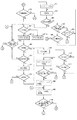
本例では、まず全2重通信により手順信号の送受信を行なう。図2は、本例の通信シーケンスを示した図である。
【0018】
着呼側は、着信に応答して、ANSam信号送出回路10からANSam信号(2100Hzを15Hzで変調した信号)を送出する。このANSam信号により公衆網のエコーサプレッサ機能又はエコーキャンセラ機能がディスイネーブル状態となり全2重通信が可能となる。発呼側は、着呼側からのANSam信号を受信すると、V.8変調によるCM信号を送出し、このCM信号により装置の有しているモデムの種類を着呼側に通知する。着呼側は、CM信号を受信すると、ANSam信号の送出を停止し、V.8変調によるJM信号を送出する。着呼側は、このJM信号によって、CM信号で通知されたモデムの種類の中で、着呼側が選択したモデムを発呼側に通知する。発呼側は、JM信号を受信するとCM信号の送出を停止し、V.8変調のCJ信号を送出する。発呼側は、このCJ信号によりJM信号に基づいて決定したモデムを着呼側に通知する。着呼側は、CJ信号を受信すると、JM信号の送出を停止し、発呼側からのラインプルービング信号の受信処理へ進む。このV.8手順で発呼側と着呼側の両方がV.34モデムを有していない(又はいずれか一方がV.34による通信を行なうように設定されていない)場合、T.30の手順に移行する。
【0019】
一方、発呼側は、CJ信号の送出を停止してから50msec経過後に回線2aの状況をチェックするためのラインプルービング信号(V.34で変調された信号)を送出する。この間の信号断は、50msecであるので、公衆網のエコーサプレッサ又はエコーキャンセラ機能はディスイネーブル状態のままである。一方、着呼側は、ラインプルービング信号を受信すると、このラインプルービング信号に対する応答信号(V.34変調の信号)を送出し、この応答信号によって、以後の信号の送出レベル、振幅レベルの補正、伝送ボーレートを発呼側に通知し、発呼側からのロングトレーニング信号の受信処理へ進む。
【0020】
発呼側は、前記応答信号を受信すると、ラインプルービング信号の送出を停止し、送出停止から50msec経過後にV.34変調のロングトレーニング信号を送出する。着呼側は、このロングトレーニング信号によりモデム8の等化器の調整、タイミング検出等の処理を実行する。
【0021】
発呼側は、ロングトレーニング信号の送出後、50msec経過後にV.34変調のパラメータ交換信号を送出する。着呼側は、パラメータ変調信号を受信すると、V.34変調のパラメータ変調応答信号を送出し、この応答信号により以降のリンク補正、ピットレート発呼側に通知する。そして、着呼側は、パラメータ交換の応答信号に続いてT.30勧告のCSI、DIS信号をV.34変調により送出し、更に発呼側からT.30勧告のTS1、DCSを受信するまでフラグ(ダミー信号)を送出する。
【0022】
発呼側は、CSI、DIS信号を受信するとパラメータ交換信号の送出を停止し、V.34変調によりTSI、DCSを送出した後、着呼側からCFR信号を受信するまでフラグを送出する。一方、着呼側は、発呼側からTSI、DCS信号を受信するとフラグ送出を停止し、V.34変調によりCFR信号を送出する。
【0023】
発呼側は、CFR信号を受信すると、フラグ送出を停止し、50msec経過後に前の手順で設定された伝送モードにより、画信号を送出し、着呼側は、設定された伝送モードにより画信号の受信を行なう。ここでの画信号の送受信は、全2重通信による誤り再送通信であってもよいし、半2重通信による誤り再送通信(ECM通信)であってもよい。
【0024】
発呼側は、1ページの画信号の送信後に、そのままの伝送モードで次ページの画信号を送出する場合には、画信号の送信終了から50msec経過後にPPS−MPS信号(T.30勧告のECMの場合)を送出した後、着呼側からMCF信号を受信するまでフラグを送出する。尚、伝送モードを変更して次ページの送信を行なう場合には、発呼側は、PPS−MPS信号に変わってPPS−EOM信号を送出する。
【0025】
着呼側は、画信号に続いてPPS−MPS信号を受信すると、画信号が良好に受信されているとMCF信号を送出した後に、次のページの画信号受信処理へ進む。
【0026】
発呼側は、MCF信号を受信すると、フラグ送出を停止し、50msec経過後に、次のページの画信号を送出する。そして、そのページが最終ページであると、そのページの画信号の送出終了後、50msec経過後にPPS−EOP信号を送出し、着呼側からMCF信号を受信するまでフラグを送出する。以上の通信処理では、50msec以上の信号断は発生しないので、エコーサプレッサ又はエコーキャンセラ機能は、ディスイネーブル状態のままである。
【0027】
発呼側は、着呼側からMCF信号を受信すると、フラグ送出を停止して、DCNを送出する。
【0028】
以上のV.8及びV.34手順において、発呼側及び着呼側は、相手先に対して手順信号の送出を開始してから所定時間経過してもその送出した手順信号に対する応答信号が受信されないと、T.30勧告に基づく半2重通信による手順へ移行する。この場合、着呼側によるNSF、CSI、DISの送出から半2重通信手順が実行される。
【0029】
以上の処理によって、全2重通信による手順が回線品質の低下により途中で実行できなくなっても、半2重通信による手順に切り換え、半2重通信手順によって残りの画信号の通信を行なうので、通信途中でエラー終了することなく、適切な画像通信を行なうことができる。
【0030】
図2〜図6は、本実施例の発呼側の制御(図3〜図5)及び着呼側の制御(図6、図7)を示したフローチャートである。
【0031】
図3において、S32では、信号線20aに信号レベル「0」の信号を出力し、CMLをオフする。
【0032】
S34では、信号線20dに、信号レベル「0」の信号を出力し、ANSam信号を送出しない設定とする。
【0033】
S36、S38では発呼、あるいは着呼が選択されたか否かが判断され、発呼が選択されるとS42に進み、着呼が選択されるとS102に進む。発呼、着呼ともに選択されていないと、S40に進み、その他の処理を行なう。
【0034】
S42では、信号線20aに信号レベル「1」の信号を出力しCMLをオンする。
【0035】
S44では、タイマーT1に35秒をセットする。
【0036】
S46では、ANSam信号、CED信号、NSF/CSI/DIS信号の受信を行ない、S48、S50、S52、S54にて夫々受信の有無を判断し、NSF/CSI/DIS信号(V.21信号)を受信すると、S60に進み、CED信号(2100Hzの信号)を受信するとS55に進み、ANSam信号(2100Hzを15Hzで変調した信号)を受信すると、S67−1に進み、T1がタイムオーバーしていないとS46に進み、T1がタイムオーバーすると、S32に進む。
【0037】
S55では、タイマーT1に35秒をセットし、S56、S57にてタイマーT1がタイムオーバーと、NSF/CSI/DIS信号の受信をチェックする。タイマーT1がタイムオーバーするまでにNSF/CSI/DIS信号が受信されると、S56からS58に進み、NSS/TSI/DCS信号を送信し、S59にてDCSで設定されたモデムの伝送スピード(V.27ter、V.29、又はV.17)でトレーニング(Tr)・TCF信号を送信し、CFRの受信後画信号の送信を行なう。
【0038】
S60では、DIS信号により相手受信機がV.8機能を有しているか否かを判断し、相手受信機がV.8機能を有しているとS61に進み、V.8機能を有していないとS58に進んで以降通常のT.30手順による画信号の送信を行なう。
【0039】
又、S60にて受信したDIS信号がV.8機能有りになっている場合、V.8手順へ移行するために、S61にてタイマーT1に35秒をセットし、S62にてV.8手順の信号であるCI信号(このCI信号により着呼側にV.8手順のANSam信号を送出させる)を送信する。そして、S63、S64、S65にて、ANSam信号の受信、NSF/CSI/DIS信号の受信、タイマーT1のタイムオーバーをチェックし、タイマーT1がタイムオーバーするまでにANSam信号が受信されるとS63からS67−1に進み、NSF/CSI/DIS信号が受信されるとS64からS66に進んで受信したDIS信号がV.8機能有りになっているか否かを判断する。S66にてDIS信号がV.8機能有りになっている場合、相手受信機がCI信号を受信できなかったものとして再びS62にてCI信号を送信するが、このときタイマーT1は再セットされないので、何度CI信号を送信してもANSam信号が受信されず、V.8機能有りのDIS信号が受信され続けても、タイマーT1のタイムオーバーでその通信をエラー終了させ待機状態に復帰できる。又、S66にて受信したDIS信号がV.8機能無しになっている場合、S58に進んで以降T.30手順により画信号の送信を行なう。
【0040】
又、ANSam信号が受信されS67−1に進むと、S67−1にて装置がV.34の通信を行なうように設定されているか否かを判断する。かかるモード設定は、操作部22によるキー入力に基づいて行なわれ、登録用メモリ24に設定されたモード情報が格納される。制御回路20は、登録用メモリ24のモード情報により装置がV.34の通信を行なうように設定されているか否かを判断する。装置がV.34の通信を行なうように設定されていると、S67−2にてV.34機能有りのCM信号の送信を開始し、他方V.34の通信を行なうように設定されていなければ、S67−3にてV.34機能無しのCM信号の送信を開始する。同時にS68にてV.8手順のJM信号の受信をチェックし、JM信号を受信するとS76に進み、JM信号を受信していないとS70に進む。
【0041】
S70では、CM信号の送信が終了したか否かを判断し、CM信号の送信が終了していなければ、S71にて、V.21によるNSF/CSI/DIS信号の受信をチェックする。S71にてNSF/CSI/DIS信号が受信されると、S58に進んで、T.30手順による画信号の送信を行なう。又、S70にてCM信号の送信が終了すると、S72に進み、JM信号の受信処理を所定期間(50msec未満)続行する。そして、S74にてJM信号の受信の有無を判定する。ここで、JM信号を受信できれば、S76に進み、V.8信号であるCJ信号を送信する。S74にてJM信号が受信されないと、全2重通信は不可と判定し、S55に進み、V21に基づいた手順(T.30手順)を行なう。
【0042】
S76に進むケースは、CM信号送信に対してJM信号が受信できた場合であるので、S76にてCJ信号を送信し、タイマーT1に35秒をセットし、S77にて装置がV.34通信を行なうように設定されているか、S78にて受信したJM信号がV.34通信を指定しているかを判断し、装置がV.34が行なうように設定され、かつJM信号によりV.34が指定されているとS80に進んで以降V.34に基づいた手順、画伝送を実行する。又、装置がV.34を行なうように設定されていない、又はJM信号によりV.34が指定されていないと、S55に進んで以降T.30手順により画信号の送信を行なう。
【0043】
S80では、ラインプルービング信号の送受信を行ない、S82にて、ラインプルービングの全2重通信が可能であるか否かを判断し、全2重通信が可能であると、S84に進み、V.34に基づいた手順、画伝送を実行する。S82にてラインプルービングの全2重通信が不可能であると、S55に進み、V.21に基づいた手順(T.30手順)を行なう。
【0044】
S84では、ロングトレーニング信号の送信を実行する。
【0045】
S86では、パラメータ交換及び、V.34信号による前手順を行ない、S88にてパラメータ交換、V.34信号にある前手順の全2重通信が、可能であるか否かを判断し、全2重通信が可能であると、S90へ進み、V.34での画伝送(画伝送は半2重通信である)をし、パラメータ変換、V.34信号による前手順の全2重通信が不可能であると、S55に進み、V.21に基づいた手順(T.30手順)を行なう。
【0046】
S92では、V.34信号による中間手順を表わしている。ここでS94にてV.34信号による中間手順の全2重通信が可能であると、S96に進み、V.34信号による中間手順の全2重通信が不可能である(手順信号の送出開始から所定時間内に応答信号が受信されない)と、S55に進み、V.21に基づいた手順(T.30手順)を行なう。
【0047】
S96では、次ページがあるか否かが判断され、次ページがあるとS98に進み、次ページがないとS100にて、V.34信号による後手順を行なう。
【0048】
S98では、モードチェンジがあるか否かを判断し、モードチェンジがあるとステップS86に進み、モードチェンジがないとS90に進む。
【0049】
次に着呼側の制御を説明する。
【0050】
図6のS102では、信号線20aに、信号レベル「1」の信号を出力し、CMLをオンする。
【0051】
S104では、信号線20dの制御により、ANSam信号の送出を開始する。
【0052】
S106では、V.8信号のCM信号の受信を行ない、ANSam信号送信終了(S114)以前に、CM信号を受信すると、S107に進み、V.8信号のJM信号を送信し、CM信号を受信できずにANSam信号の送出が終了すると、S115に進む。
【0053】
ANSam信号の送出中にCM信号が受信されS107に進むと、受信したCM信号がV.34機能有りになっているか否か(相手送信機がV.34機能を有しているか否か)を判断する。相手送信機がV.34機能を有していると、S109にてV.34を指定するJM信号の送信を開始し、他方、相手送信機がV.34機能を有していないと、S108にてV.21(又は、V.27ter、又はV.29、又はV.17)を指定するJM信号の送信を開始する。そして、S110、S112にてCJ信号の受信と、JM信号の送信終了をチェックし、JM信号の送信が終了するまで(JM信号の送信中)にCJ信号が受信されると、S110からS111に進み、他方、CJ信号が受信できずにJM信号の送信が終了すると、全2重通信は不可と判断してS113−1に進み、以降T.30手順による画信号の受信処理へ移行する。
【0054】
CJ信号が受信されS111に進むと、S111にてJM信号でV.34を指定したか否かを判断し、V.34を指定した場合には、S120に進み、V.34手順、V.34による画信号の受信処理へ移行する。
【0055】
S113−1では、タイマーT1に35秒をセットし、S113−2にて、タイマーT2に3秒をセットし、S113−3にてNSF/CSI/DIS信号を送信する。このとき、DIS信号としては、V.8機能無しに設定したDIS信号を送信され、これにより相手送信器で再びV.8手順が繰り返されることを防止し、速やかにかつ確実にT.30手順へ以降できる。S113−4、S113−5、S113−6では、NSS/TSI/DCS信号の受信、タイマーT2のタイムオーバー、タイマーT1のタイムオーバーをチェックし、3秒間隔でNSF/CSI/DIS信号を送信し、タイマーT1がタイムオーバーするまでにNSS/TSI/DCS信号が受信されると、S113−4からS118に進んで受信したDCS信号により指定されたモデムの伝送スピード(V.27ter、V.29、又はV.17)でトレーニング(Tr)、TCF信号を受信し、TCF信号の受信状態がよければCFR信号を送信して、設定したモデムの伝送スピードで画信号の受信を行なう。
【0056】
又、ANSam信号の送出中(約3秒間)にCM信号が受信されないとS114からS115に進み、S115にてタイマーT1に35秒をセットし、S116にてタイマーT2に3秒をセットし、S117−1にてV.21によりNSF/CSI/DIS信号を送信する。このときDIS信号としては、V.8機能有りに設定したDIS信号を送信する。これは、着信に応答してANSam信号を送信したものの、発呼元(相手送信機)がマニュアル送信指示の入力タイミングが遅くなってしまった等の理由により、ANSam信号を受信できなかった場合に、CI信号の送信から再度V.8手順を行なえるようにするためである。
【0057】
S117−2、S117−3、S119−1、S119−2では、V.8手順のCI信号の受信、V.21のNSS/TSI/DCS信号の受信、タイマーT2のタイムオーバー、タイマーT1のタイムオーバーをチェックし、CI信号が受信されるとS117−2からS104に進んでANSam信号の送信を行ない、他方、NSS/TSI/DCS信号が受信されるとS117−3からS118に進んで、T.30手順による画信号の受信を行なう。又、タイマーT2(3秒)がタイムオーバーするとS119−1からS116に進んで再度NSF/CSI/DIS信号を送信し、3秒間隔でNSF/CSI/DIS信号を送信するようにし、タイマーT1がタイムオーバーするまでにCI信号も、NSS/TSI/DCS信号も受信されないとその通信をエラー終了し待機状態へ戻る。尚、ここでS117−1で送信するNSF/CSI/DIS信号(V.8機能有り)の送出回数をカウントするようにし、所定回数(例えば5回)送出してもCI信号とNSS/TSI/DCS信号のいずれも受信されない場合に、S113−2に進んでV.8機能無しのDIS信号を送出するようにしてもよい。これによって、相手送信機からのCI信号が正常受信できずにエラー終了する代わりに、T.30手順での画信号の通信へ移行できる。
【0058】
又、V.34手順、V.34の通信を行なうべくS111からS120に進むと、S120にて、ラインプルービング信号の受信と、それに対する応答信号の送信を行なう。ここで、S122にて、ラインプルービングの全2重通信が可であるとS124に進み、ロングトレーニング信号の受信をし、ラインプルービングの全2重通信が不可であるとS113−1に進む。
【0059】
S124では、ロングトレーニングの受信を行なう。
【0060】
S126では、パラメータ変換、V.34信号による前手順を行なう。ここでS128にて、パラメータ変換、V.34信号による前手順の全2重通信が可であると、S130に進み、V.34での画信号の受信へ移行する。S128にてパラメータ変換、V.34信号による前手順の全2重通信が不可であると、S113−1に進む。
【0061】
S132では、V.34信号による中間手順を実行する。ここで、S134にてV.34信号による仲間手順での全2重通信が可能であると、S136に進み、V.34信号による中間手順での全2重通信が不可能であると、S113−1に進む。
【0062】
S136では、次ページがあるか否かが判断され、次ページがあると、S140に進み、次ページがないと、S138にてV.34信号による後手順を行なう。
【0063】
S140では、モードチェンジがあるか否かが判断され、モードチェンジがあるとS126に進み、モードチェンジがないとS130に進む。
【0064】
以上の処理によって、図2に示される通信シーケンスが発呼側及び着呼側で実行される。図8は、発呼側でのマニュアル送信指示の入力タイミングが遅れたことにより、CI信号の通信からV.8手順が実行される例を示した通信シーケンスである。
【0065】
以上の実施の形態によれば、発呼側(送信側)がV.8機能有りのDIS信号の受信に応答して、CI信号を送信し、着呼側(受信側)がCI信号の受信に失敗している場合に、送信側が再度CI信号の送信を行なう。又、V.8手順を実行した時、送信側と受信側のいずれか一方がV.34機能を有していない場合には、T.30手順へ移行するようにし、このとき受信側がV.8機能無しのDIS信号を送信する(V.8機能有りと宣言しない)ことにより速やかにかつ確実にT.30手順による画信号通信を行なうことができる。
【0066】
次に、本発明の他の実施の形態について説明する。
【0067】
ファクシミリ装置によっては、通信時間を短くするために通常のT.30手順と異なる特殊な手順(短縮手順)を実行するものがある。図9は、特殊手順(短縮手順)の例を示した図である。
【0068】
図9において、受信機側が送信するプリアンブル、NSF、CSI、DIS信号はV.21の信号でかつプリアンブルの送信時間は1秒であり、通常のT.30手順と同一である。ここでNSF信号により短縮手順の機能の有無を送信機に通知する。送信機は、短縮手順を実行する場合V.21のプリアンブル、NSS信号を送信する。ここで、プリアンブルの時間は300msとする。さらに、ここでのNSS信号は、概略機能の通知をする。そして、V.17のTr(トレーニング)、NSS、画信号の送信、そしてEOP信号の送信へ移行する。この高速のNSS信号では、詳細機能の通知を行なう。その後、受信機からV.21のプリアンブル、MCF信号、送信機からV.21のプリアンブル、EOP信号の送信を行なうが、これらのプリアンブルの時間は300msである。このような短縮手順の機能を有する装置が特に図8に示す通信シーケンスを行なう場合、受信側では、CI信号を受信するタイミングで短いプリアンブルのNSS信号が受信されることがある。
【0069】
従って受信機側では、CI信号と短いプリアンブルのNSS信号を識別しなければならないが、CI信号と短いプリアンブルのNSS信号の信号パターンがほぼ同じなために受信側では識別するのが困難である。その為に、V.8手順を優先させた場合には、図9に示すような短縮手順を実行できない。
【0070】
そこで、短縮手順を優先して行なうように設定されている場合には、図8のシーケンスで最初のANSam信号の送信に続いて、NSF/CSI/DIS信号を送信する際、V.8機能無しのDIS信号を送信し、これによって送信側からCI信号が送信されないようにして、短いプリアンブルのNSS信号の受信を行なうようにする。
【0071】
図10は、他の実施の形態における制御動作を示したフローチャートであり、図6のS114とS115の間に図10に示すS142〜S158の処理が追加される。
【0072】
S142では、操作部22のキー入力により短縮手順を優先するモードが選択されているか否かを判断し、短縮手順を優先するモードが選択されていなければ、図6のS115に進み、短縮手順を優先するモードが選択されているとS144にてタイマーT1に35秒をセットし、S146にてタイマーT2に3秒をセットする。そして、S148にてNSF(短縮手順機能有りのNSF)/CSI/DIS(V.8機能無しのDIS)信号を送信する。そして、S150、S152、S154、S156にて、NSS/TSI/DCS信号の受信、短縮手順のNSS信号の受信、タイマーT2のタイムオーバー、タイマーT1のタイムオーバーをチェックし、3秒間隔でNSF/CSI/DIS信号を送出しながら、タイマーT1がタイムオーバーするまでに通常のNSS/TSI/DCS信号が受信されるとS150から図6のS118に進み、T.30手順による画信号の受信へ移行し、短縮手順のNSS信号が受信されるとS152からS158に進んで図9に示す短縮手順による画信号の受信処理を行なう。そして、タイマーT1がタイムオーバーすると、図3のS32に進み待機状態に戻る。
【0073】
以上の様に他の実施の形態によれば、短縮手順を実行することが可能となる。
【0074】
又、本発明は、上述した実施の形態に限らず種々の変形が可能である。
【0075】
【発明の効果】
以上の様に本発明によれば、V.8手順を適切に実行できる。又、V.8手順からT.30手順への以降を速やかにかつ適切に行なうことができる。
【図面の簡単な説明】
【図1】本実施の形態のファクシミリ装置の構成を示したブロック図である。
【図2】本実施の形態による通信シーケンスを示した図である。
【図3】本実施の形態の制御動作を示したフローチャート図である。
【図4】本実施の形態の制御動作を示したフローチャート図である。
【図5】本実施の形態の制御動作を示したフローチャート図である。
【図6】本実施の形態の制御動作を示したフローチャート図である。
【図7】本実施の形態の制御動作を示したフローチャート図である。
【図8】マニュアル送信指示が遅れた場合の通信シーケンスを示した図である。
【図9】短縮手順の通信シーケンスを示した図である。
【図10】他の実施の形態の制御動作を示したフローチャートである。
【符号の説明】
2 NCU
4 電話機
6 ハイブリッド回路
8 モデム
10 ディスイネーブル信号送出回路
12 加算回路
14 読取部
16 記録部
18 画像メモリ
20 制御回路
22 操作部
24 登録メモリ[0001]
BACKGROUND OF THE INVENTION
The present invention provides a V.100 for identifying the type of modem. The present invention relates to a facsimile apparatus having eight procedures and a facsimile communication method.
[0002]
[Prior art]
In recent years, various types of communication such as communication by a personal computer and facsimile communication are performed through a general public line. Various modems are used for such communication. In particular, in computer communication, communication unique to each company is performed, and communication cannot be performed unless the same type of modem is used on the transmission side and the reception side. Therefore, a procedure (V.8 procedure) has been proposed in which the types of modems on the transmitting side and the receiving side are identified and the modems that are shared are specified.
[0003]
This V. The eight procedures are executed by full duplex communication. According to 8 procedures, V. Select 34 modem and select V. It is considered that a communication procedure is executed by full duplex communication using a 34 modem and image communication is performed by half duplex communication.
[0004]
[Problems to be solved by the invention]
V. mentioned above. When the function of 8 procedures is provided in the facsimile apparatus, the conventional T.D. V. Communication with a facsimile machine having only 30 procedures and V. Although it does not have 34 functions, It is also necessary to realize communication with a facsimile machine having eight procedures.
[0005]
[Means for Solving the Problems]
In the present invention, V.I. In response to reception of a digital identification signal indicating the presence of 8 functions, V. The first signal indicating the eight procedures is transmitted. In response to reception of the modulated tone signal of 8 procedures, V. 8 procedure, the modulation tone signal is not received and the V.V. When the digital identification signal indicating the presence of 8 functions is received, the first signal is transmitted again. Even if communication of the first signal fails once, V. 8 procedures can be executed.
[0006]
V. After execution of the 8 steps, the partner device or its own device If it does not have 34 functions, A digital identification signal including information indicating that there is no
[0007]
DETAILED DESCRIPTION OF THE INVENTION
Hereinafter, embodiments of the present invention will be described in detail with reference to the drawings.
[0008]
FIG. 1 is a block diagram showing a configuration of a facsimile apparatus according to an embodiment of the present invention.
[0009]
In the figure,
[0010]
The
[0011]
[0012]
10 disables the echo suppressor or echo canceller function of the public network. The ANSam signal for transmitting / receiving the full duplex communication procedure signal of 8 (a signal obtained by modulating a signal of 2100 Hz) to the line 2a through the
[0013]
Reference numeral 14 denotes a reading unit for reading a document, and reference numeral 16 denotes a recording unit that records an image signal as an image.
[0014]
[0015]
[0016]
Next, an outline of the operation of the facsimile apparatus according to the present embodiment will be described.
[0017]
In this example, procedure signals are first transmitted and received by full duplex communication. FIG. 2 is a diagram showing a communication sequence of this example.
[0018]
In response to the incoming call, the called side sends out an ANSam signal (a signal obtained by modulating 2100 Hz with 15 Hz) from the ANSam
[0019]
On the other hand, the calling side sends a line probing signal (a signal modulated by V.34) for checking the status of the line 2a after 50 msec has passed since the sending of the CJ signal is stopped. Since the signal interruption during this period is 50 msec, the echo suppressor or echo canceller function of the public network remains disabled. On the other hand, when the callee receives the line probing signal, it sends a response signal (V.34 modulation signal) to the line probing signal, and the response signal corrects the transmission level and amplitude level of the subsequent signals, The transmission baud rate is notified to the calling side, and the process proceeds to reception processing of a long training signal from the calling side.
[0020]
When the calling side receives the response signal, the calling side stops sending the line probing signal. 34 modulation long training signal is sent out. The called party performs processing such as adjustment of the equalizer of the
[0021]
The calling party sends a V.V. signal after 50 msec has elapsed since the transmission of the long training signal. A 34 modulation parameter exchange signal is transmitted. When the called party receives the parameter modulation signal, V. A 34-modulation parameter modulation response signal is transmitted, and the subsequent link correction and pit rate calling side are notified by this response signal. Then, the callee receives the parameter exchange response signal followed by T.P. 30 CSI and DIS signals of V.30 recommendation. 34 is transmitted by modulation, and the caller also sends T.P. Flags (dummy signals) are sent until TS30 and DCS of 30 recommendation are received.
[0022]
When the calling side receives the CSI and DIS signals, it stops sending parameter exchange signals. After sending TSI and DCS by 34 modulation, a flag is sent until a CFR signal is received from the called side. On the other hand, when the called side receives the TSI and DCS signals from the calling side, it stops sending the flag. A CFR signal is transmitted by 34 modulation.
[0023]
When the calling side receives the CFR signal, it stops sending the flag, and after 50 msec has passed, sends the image signal in the transmission mode set in the previous procedure, and the called side sends the image signal in the set transmission mode. Is received. The transmission / reception of the image signal here may be error retransmission communication by full-duplex communication or error retransmission communication (ECM communication) by half-duplex communication.
[0024]
When transmitting the image signal of the next page in the transmission mode as it is after the transmission of the image signal of one page, the calling side transmits the PPS-MPS signal (in accordance with T.30 recommendation) after 50 msec from the end of the transmission of the image signal. In the case of ECM), a flag is sent until an MCF signal is received from the called side. When the transmission mode is changed and the next page is transmitted, the calling side transmits a PPS-EOM signal instead of the PPS-MPS signal.
[0025]
When the callee receives the PPS-MPS signal following the image signal, if the image signal is received well, it sends an MCF signal and then proceeds to the image signal reception process for the next page.
[0026]
When the calling side receives the MCF signal, it stops sending the flag, and after the elapse of 50 msec, sends the image signal of the next page. If the page is the last page, a PPS-EOP signal is sent after the elapse of 50 msec after transmission of the image signal of the page, and a flag is sent until an MCF signal is received from the called side. In the above communication processing, signal interruption of 50 msec or more does not occur, so the echo suppressor or echo canceller function remains in the disabled state.
[0027]
When the calling side receives the MCF signal from the called side, the calling side stops sending the flag and sends the DCN.
[0028]
V. above. 8 and V.I. In 34 procedures, if the calling side and the called side do not receive a response signal for the transmitted procedure signal even after a predetermined time has elapsed since the start of transmission of the procedure signal to the other party, The procedure shifts to a half-duplex communication procedure based on the 30 recommendation. In this case, the half-duplex communication procedure is executed from the sending of the NSF, CSI, and DIS by the called party.
[0029]
With the above processing, even if the procedure by full duplex communication cannot be executed halfway due to the deterioration of the line quality, the procedure is switched to the half duplex communication procedure, and the remaining image signals are communicated by the half duplex communication procedure. Appropriate image communication can be performed without terminating the error during communication.
[0030]
2 to 6 are flowcharts showing the calling side control (FIGS. 3 to 5) and the incoming side control (FIGS. 6 and 7) of the present embodiment.
[0031]
In FIG. 3, in S32, a signal level “0” is output to the signal line 20a, and the CML is turned off.
[0032]
In S34, the signal level “0” is output to the
[0033]
In S36 and S38, it is determined whether an outgoing call or an incoming call is selected. If a outgoing call is selected, the process proceeds to S42, and if an incoming call is selected, the process proceeds to S102. If neither outgoing call nor incoming call is selected, the process proceeds to S40 to perform other processes.
[0034]
In S42, a signal level “1” is output to the signal line 20a to turn on the CML.
[0035]
In S44, the timer T1 is set to 35 seconds.
[0036]
In S46, the ANSam signal, the CED signal, and the NSF / CSI / DIS signal are received. In S48, S50, S52, and S54, the presence / absence of reception is determined, and the NSF / CSI / DIS signal (V.21 signal) is received. If received, the process proceeds to S60, and if a CED signal (2100 Hz signal) is received, the process proceeds to S55. If an ANSam signal (a signal obtained by modulating 2100 Hz at 15 Hz) is received, the process proceeds to S67-1, and if T1 has not timed out, S46 If T1 times out, the process proceeds to S32.
[0037]
In S55, the timer T1 is set to 35 seconds, and in S56 and S57, the timer T1 checks whether the time is over and the reception of the NSF / CSI / DIS signal. If the NSF / CSI / DIS signal is received before the timer T1 times out, the process proceeds from S56 to S58, where the NSS / TSI / DCS signal is transmitted, and the modem transmission speed (V.V. 27ter, V.29, or V.17), a training (Tr) / TCF signal is transmitted, and a CFR-received image signal is transmitted.
[0038]
In S60, the partner receiver receives the V.D. It is determined whether or not the other receiver has V.8 function. If it has 8 functions, the process proceeds to S61. If it does not have 8 functions, the process proceeds to S58 and thereafter normal T.P. The image signal is transmitted in 30 steps.
[0039]
The DIS signal received at S60 is V.V. If there are 8 functions, V. In order to shift to step 8, 35 seconds is set in timer T1 in S61, and V. is set in S62. A CI signal that is an 8-procedure signal (which causes the called party to transmit an ANSam signal of the V.8 procedure by this CI signal) is transmitted. In S63, S64, and S65, the reception of the ANSam signal, the reception of the NSF / CSI / DIS signal, and the timer T1 time-over are checked. If the ANSam signal is received before the timer T1 has timed-out, the process proceeds from S63 to S67-. 1, when the NSF / CSI / DIS signal is received, the process proceeds from S64 to S66 and the received DIS signal becomes V.1. It is determined whether or not there are 8 functions. In S66, the DIS signal is V.V. If eight functions are present, the receiver receiver transmits the CI signal again in S62, assuming that the receiver receiver has not received the CI signal. At this time, the timer T1 is not reset. However, no ANSam signal is received. Even if a DIS signal with 8 functions continues to be received, the communication can be terminated with an error when the timer T1 expires and the standby state can be restored. Further, the DIS signal received in S66 is V.V. If there are no 8 functions, the process proceeds to S58 and thereafter T.M. The image signal is transmitted in 30 steps.
[0040]
When the ANSam signal is received and the process proceeds to S67-1, the apparatus is connected to the V.S. It is determined whether or not it is set to perform
[0041]
In S70, it is determined whether or not the transmission of the CM signal is completed. If the transmission of the CM signal is not completed, the V.S. Check the reception of the NSF / CSI / DIS signal by 21. When the NSF / CSI / DIS signal is received in S71, the process proceeds to S58 and T.H. The image signal is transmitted in 30 steps. When the transmission of the CM signal is completed in S70, the process proceeds to S72, and the JM signal reception process is continued for a predetermined period (less than 50 msec). In S74, it is determined whether or not a JM signal has been received. Here, if the JM signal can be received, the process proceeds to S76 and V.D. The CJ signal which is 8 signals is transmitted. If the JM signal is not received in S74, it is determined that full duplex communication is not possible, and the process proceeds to S55 to perform a procedure based on V21 (T.30 procedure).
[0042]
The case where the process proceeds to S76 is a case where the JM signal can be received in response to the CM signal transmission, so the CJ signal is transmitted in S76, 35 seconds is set in the timer T1, and the device is set to V.S. 34, or the JM signal received in S78 is V.34. 34 determines whether or not communication is designated, 34 is set to be performed, and V.V. If 34 is designated, the process proceeds to S80 and thereafter V.34. 34, image transmission is executed. In addition, the device is V.V. 34 is not set to perform 34 or V.V. If 34 is not designated, the process proceeds to S55 and thereafter T.34. The image signal is transmitted in 30 steps.
[0043]
In S80, the line probing signal is transmitted and received. In S82, it is determined whether or not full-duplex communication of line probing is possible. If full-duplex communication is possible, the process proceeds to S84. 34, image transmission is executed. If full-duplex communication of line probing is not possible in S82, the process proceeds to S55, where The procedure based on 21 (T.30 procedure) is performed.
[0044]
In S84, a long training signal is transmitted.
[0045]
In S86, parameter exchange and V.S. 34. Perform pre-procedure with 34 signals, exchange parameters in S88, 34, it is determined whether or not the full-duplex communication of the previous procedure in the 34 signal is possible. If the full-duplex communication is possible, the process proceeds to S90. 34 (image transmission is half-duplex communication), parameter conversion, V. If full-duplex communication in the pre-procedure using the 34 signal is not possible, the process proceeds to S55, and The procedure based on 21 (T.30 procedure) is performed.
[0046]
In S92, V.I. It represents an intermediate procedure with 34 signals. Here, V. If the full-duplex communication of the intermediate procedure using 34 signals is possible, the process proceeds to S96, where If the full-duplex communication of the intermediate procedure using the 34 signal is impossible (the response signal is not received within a predetermined time from the start of sending the procedure signal), the process proceeds to S55, where The procedure based on 21 (T.30 procedure) is performed.
[0047]
In S96, it is determined whether or not there is a next page. If there is a next page, the process proceeds to S98. The post-procedure is performed using the 34 signal.
[0048]
In S98, it is determined whether or not there is a mode change. If there is a mode change, the process proceeds to step S86, and if there is no mode change, the process proceeds to S90.
[0049]
Next, the control on the called side will be described.
[0050]
In S102 of FIG. 6, a signal level “1” is output to the signal line 20a, and the CML is turned on.
[0051]
In S104, transmission of the ANSam signal is started under the control of the
[0052]
In S106, V.I. If the CM signal is received before the end of ANSam signal transmission (S114), the process proceeds to S107. When eight JM signals are transmitted and the CM signal cannot be received and the transmission of the ANSam signal is completed, the process proceeds to S115.
[0053]
When a CM signal is received during transmission of the ANSam signal and the process proceeds to S107, the received CM signal is changed to V.P. It is determined whether or not the 34 function is present (whether or not the partner transmitter has the V.34 function). The other transmitter is V. If it has 34 functions, V. 34 starts transmission of a JM signal designating 34. If it does not have the 34 function, V.S. The transmission of the JM signal designating 21 (or V.27ter, V.29, or V.17) is started. Then, the reception of the CJ signal and the end of transmission of the JM signal are checked in S110 and S112, and if the CJ signal is received until the transmission of the JM signal is completed (during transmission of the JM signal), the process proceeds from S110 to S111. On the other hand, when the transmission of the JM signal is completed without receiving the CJ signal, it is determined that the full duplex communication is impossible, and the process proceeds to S113-1, and thereafter, the T.D. The process proceeds to image signal reception processing according to 30 procedures.
[0054]
When the CJ signal is received and the process proceeds to S111, the V.V. It is determined whether or not V.34 is designated. If 34 is designated, the process proceeds to S120 and V.34. 34 procedures. The process proceeds to the image
[0055]
In S113-1, the timer T1 is set to 35 seconds, in S113-2, the timer T2 is set to 3 seconds, and in S113-3, the NSF / CSI / DIS signal is transmitted. At this time, as the DIS signal, V.V. The DIS signal set to no function is transmitted, so that the V. 8 procedures are prevented from being repeated, and T.I. After 30 steps. In S113-4, S113-5, and S113-6, the reception of the NSS / TSI / DCS signal, the timer T2 time-over, and the timer T1 time-over are checked, and the NSF / CSI / DIS signal is transmitted at intervals of 3 seconds. If the NSS / TSI / DCS signal is received before T1 times out, the process proceeds from S113-4 to S118 and the transmission speed (V.27ter, V.29, or V.29) of the modem designated by the received DCS signal. In step 17), training (Tr) and a TCF signal are received. If the reception state of the TCF signal is good, the CFR signal is transmitted, and the image signal is received at the set transmission speed of the modem.
[0056]
If the CM signal is not received during the transmission of the ANSam signal (about 3 seconds), the process proceeds from S114 to S115. In S115, the timer T1 is set to 35 seconds, and in S116, the timer T2 is set to 3 seconds. -1. 21 sends an NSF / CSI / DIS signal. At this time, V. Send DIS signal set to 8 functions. This is when an ANSam signal is transmitted in response to an incoming call, but the ANSam signal cannot be received because the input source of the manual transmission instruction has been delayed by the caller (partner transmitter). From the transmission of the CI signal, V. This is because eight procedures can be performed.
[0057]
In S117-2, S117-3, S119-1, and S119-2, V.S. 8 procedure CI signal reception; 21 NSS / TSI / DCS signal reception, timer T2 time-over, timer T1 time-over are checked, and CI signal is received, the process proceeds from S117-2 to S104 to transmit the ANSam signal. When the TSI / DCS signal is received, the process proceeds from S117-3 to S118. The image signal is received in 30 steps. When timer T2 (3 seconds) expires, the process proceeds from S119-1 to S116, and the NSF / CSI / DIS signal is transmitted again, and the NSF / CSI / DIS signal is transmitted at intervals of 3 seconds. If neither the CI signal nor the NSS / TSI / DCS signal is received, the communication ends with an error and returns to the standby state. Here, the number of transmissions of the NSF / CSI / DIS signal (with V.8 function) transmitted in S117-1 is counted, and the CI signal and the NSS / TSI / If none of the DCS signals are received, the process proceeds to S113-2 and the V.D. A DIS signal without 8 functions may be transmitted. As a result, the CI signal from the partner transmitter cannot be normally received and the process ends in error. It is possible to shift to image signal communication in 30 procedures.
[0058]
V. 34 procedures. When the process proceeds from S111 to S120 to perform the communication of 34, the line probing signal is received and the response signal is transmitted in S120. Here, in S122, if full-duplex communication of line probing is possible, the process proceeds to S124, a long training signal is received, and if full-duplex communication of line probing is impossible, the process proceeds to S113-1.
[0059]
In S124, long training is received.
[0060]
In S126, parameter conversion, V.S. Pre-procedure with 34 signals. Here, in S128, parameter conversion, V.P. If the full duplex communication of the pre-procedure using the 34 signal is possible, the process proceeds to S130, and The process proceeds to reception of an image signal at 34. In S128, parameter conversion is performed. If full duplex communication in the pre-procedure using 34 signals is not possible, the process proceeds to S113-1.
[0061]
In S132, V.I. An intermediate procedure with 34 signals is executed. Here, in S134, V.P. If full duplex communication is possible in the fellow procedure using 34 signals, the process proceeds to S136, and If full-duplex communication is not possible in the intermediate procedure using 34 signals, the process proceeds to S113-1.
[0062]
In S136, it is determined whether or not there is a next page. If there is a next page, the process proceeds to S140. The post-procedure is performed using the 34 signal.
[0063]
In S140, it is determined whether or not there is a mode change. If there is a mode change, the process proceeds to S126, and if there is no mode change, the process proceeds to S130.
[0064]
With the above processing, the communication sequence shown in FIG. 2 is executed on the calling side and the called side. FIG. 8 shows that the input timing of the manual transmission instruction on the calling side is delayed and the V.V. It is the communication sequence which showed the example in which 8 procedures are performed.
[0065]
According to the above embodiment, the calling side (transmission side) is the V.C. In response to the reception of the DIS signal with 8 functions, the CI signal is transmitted. When the called side (reception side) fails to receive the CI signal, the transmission side transmits the CI signal again. V. When 8 procedures are executed, either the sending side or the receiving side is V. If it does not have 34 function, 30. At this time, the receiving side is set to V.30. By transmitting a DIS signal with no 8 function (not declared as having V.8 function), the T.D. Image signal communication according to 30 procedures can be performed.
[0066]
Next, another embodiment of the present invention will be described.
[0067]
Depending on the facsimile apparatus, a normal T.P. Some perform a special procedure (shortening procedure) different from 30 procedures. FIG. 9 is a diagram illustrating an example of a special procedure (shortening procedure).
[0068]
In FIG. 9, the preamble, NSF, CSI, and DIS signals transmitted from the receiver side are V.16. 21 and the preamble transmission time is 1 second. It is the same as 30 procedures. Here, the transmitter is notified of the presence or absence of the function of the shortening procedure by the NSF signal. When the transmitter performs the shortening procedure, the V. 21 preambles and NSS signals are transmitted. Here, the preamble time is 300 ms. Further, the NSS signal here notifies the general function. And V. The process proceeds to 17 Tr (training), NSS, image signal transmission, and EOP signal transmission. This high-speed NSS signal notifies the detailed function. Thereafter, V.V. 21 preamble, MCF signal, V. 21 preambles and EOP signals are transmitted, and the time of these preambles is 300 ms. When a device having such a shortened procedure function performs the communication sequence shown in FIG. 8 in particular, a short preamble NSS signal may be received at the reception side at the timing of receiving a CI signal.
[0069]
Therefore, the receiver side must identify the CI signal and the short preamble NSS signal, but it is difficult to identify the CI signal and the short preamble NSS signal because the signal patterns of the CI signal and the short preamble NSS signal are substantially the same. Therefore, V. When priority is given to 8 procedures, the shortening procedure as shown in FIG. 9 cannot be executed.
[0070]
Therefore, when it is set so that the shortening procedure is performed with priority, when the NSF / CSI / DIS signal is transmitted following the transmission of the first ANSam signal in the sequence of FIG. A DIS signal having no 8 functions is transmitted, so that a CI signal is not transmitted from the transmitting side, and an NSS signal with a short preamble is received.
[0071]
FIG. 10 is a flowchart showing a control operation in another embodiment, and the processes of S142 to S158 shown in FIG. 10 are added between S114 and S115 of FIG.
[0072]
In S142, it is determined whether or not a mode that prioritizes the shortening procedure is selected by key input on the
[0073]
As described above, according to another embodiment, a shortening procedure can be executed.
[0074]
The present invention is not limited to the above-described embodiment, and various modifications can be made.
[0075]
【The invention's effect】
As described above, according to the present invention, V.V. Eight procedures can be properly executed. V. From 8 procedures to T.W. The subsequent steps to 30 procedures can be performed promptly and appropriately.
[Brief description of the drawings]
FIG. 1 is a block diagram illustrating a configuration of a facsimile apparatus according to an embodiment.
FIG. 2 is a diagram showing a communication sequence according to the present embodiment.
FIG. 3 is a flowchart showing a control operation of the present embodiment.
FIG. 4 is a flowchart showing a control operation of the present embodiment.
FIG. 5 is a flowchart showing a control operation of the present embodiment.
FIG. 6 is a flowchart showing a control operation of the present embodiment.
FIG. 7 is a flowchart showing a control operation of the present embodiment.
FIG. 8 is a diagram showing a communication sequence when a manual transmission instruction is delayed.
FIG. 9 is a diagram showing a communication sequence of a shortening procedure.
FIG. 10 is a flowchart illustrating a control operation according to another embodiment.
[Explanation of symbols]
2 NCU
4 Telephone
6 Hybrid circuit
8 Modem
10 Disenable signal transmission circuit
12 Adder circuit
14 Reading unit
16 Recording section
18 Image memory
20 Control circuit
22 Operation unit
24 Registered memory
Claims (5)
V.8手順の変調トーン信号の受信に応じてV.8手順を実行し、
V.8機能有りを示すデジタル識別信号の受信に応じて、V.8手順を示す第1の信号を送信したにも関わらず、前記変調トーン信号が受信されずに、前記V.8機能有りを示す情報を含む前記デジタル識別信号が受信された場合において、再度前記第1の信号を送信することを特徴とするファクシミリ通信方法。V. In response to receiving the digital identification signal including information indicating that the digital camera has the 8 functions, Send a first signal indicating 8 steps,
V. In response to reception of the modulated tone signal of 8 procedures, V. Perform 8 steps,
V. In response to reception of a digital identification signal indicating the presence of 8 functions, V. Although the first signal indicating the eight procedures is transmitted, the modulation tone signal is not received and the V.V. 8. A facsimile communication method , wherein the first signal is transmitted again when the digital identification signal including information indicating that eight functions are present is received.
Priority Applications (6)
| Application Number | Priority Date | Filing Date | Title |
|---|---|---|---|
| JP01659896A JP3658070B2 (en) | 1996-02-01 | 1996-02-01 | Facsimile apparatus and facsimile communication method |
| CN97102366A CN1109432C (en) | 1996-02-01 | 1997-01-30 | Facsimile apparatus having V.8 protocol facility and facsimile communication method |
| EP05010263A EP1562364A3 (en) | 1996-02-01 | 1997-01-31 | Facsimile apparatus having V.8 protocol facility and facsimile communication method |
| US08/797,666 US6437870B1 (en) | 1996-02-01 | 1997-01-31 | Facsimile apparatus having V.8 protocol facility and facsimile communication method |
| EP97101546A EP0788274B1 (en) | 1996-02-01 | 1997-01-31 | Facsimile apparatus having v.8 protocol facility and facsimile communication method |
| DE69733785T DE69733785T2 (en) | 1996-02-01 | 1997-01-31 | Facsimile machine with v.8 protocol capability and facsimile transmission method |
Applications Claiming Priority (1)
| Application Number | Priority Date | Filing Date | Title |
|---|---|---|---|
| JP01659896A JP3658070B2 (en) | 1996-02-01 | 1996-02-01 | Facsimile apparatus and facsimile communication method |
Related Child Applications (1)
| Application Number | Title | Priority Date | Filing Date |
|---|---|---|---|
| JP2003346878A Division JP3631239B2 (en) | 2003-10-06 | 2003-10-06 | Facsimile apparatus and facsimile communication method |
Publications (2)
| Publication Number | Publication Date |
|---|---|
| JPH09214716A JPH09214716A (en) | 1997-08-15 |
| JP3658070B2 true JP3658070B2 (en) | 2005-06-08 |
Family
ID=11920740
Family Applications (1)
| Application Number | Title | Priority Date | Filing Date |
|---|---|---|---|
| JP01659896A Expired - Lifetime JP3658070B2 (en) | 1996-02-01 | 1996-02-01 | Facsimile apparatus and facsimile communication method |
Country Status (5)
| Country | Link |
|---|---|
| US (1) | US6437870B1 (en) |
| EP (2) | EP1562364A3 (en) |
| JP (1) | JP3658070B2 (en) |
| CN (1) | CN1109432C (en) |
| DE (1) | DE69733785T2 (en) |
Families Citing this family (14)
| Publication number | Priority date | Publication date | Assignee | Title |
|---|---|---|---|---|
| US6266379B1 (en) | 1997-06-20 | 2001-07-24 | Massachusetts Institute Of Technology | Digital transmitter with equalization |
| JP3426122B2 (en) | 1997-11-05 | 2003-07-14 | パナソニック コミュニケーションズ株式会社 | Data communication device |
| JPH11298705A (en) | 1998-04-13 | 1999-10-29 | Nec Corp | Facsimile equipment and facsimile communication method therefor |
| US7046382B1 (en) * | 1999-06-30 | 2006-05-16 | Conexant Systems, Inc. | Network latency recovery for internet gateways |
| JP2002185738A (en) * | 2000-12-13 | 2002-06-28 | Nec Corp | Facsimile communication method |
| JP2002218191A (en) * | 2001-01-22 | 2002-08-02 | Murata Mach Ltd | Communication terminal and recording medium with communication control program recorded thereon |
| US7167469B2 (en) * | 2001-02-09 | 2007-01-23 | Lsi Logic Corporation | Method for eliminating multiple modulation and demodulation of Voice band Data communication over packet and low data rate digital networks |
| US6821661B2 (en) * | 2001-08-31 | 2004-11-23 | Plug Power, Inc. | Hydrophilic anode gas diffusion layer |
| US7511861B2 (en) * | 2002-08-30 | 2009-03-31 | Hewlett-Packard Development Company, L.P. | Multi-page facsimile method and device |
| CN100456736C (en) * | 2004-08-27 | 2009-01-28 | 华为技术有限公司 | Method for realizing high-speed facsimile service in communication network |
| US8441669B2 (en) * | 2010-03-02 | 2013-05-14 | Cisco Technology, Inc. | SG3-to-G3 fax spoof |
| US8422062B2 (en) * | 2010-05-10 | 2013-04-16 | Xerox Corporation | Apparatus and method for facsimile transmission configuration |
| ITTO20110731A1 (en) * | 2011-08-05 | 2013-02-06 | Inst Rundfunktechnik Gmbh | DIGITAL UMSCHALTSIGNALSEQUENZ FUER UMSCHALTZWECKE, GERAET ZUM UNTERBRINGEN DIESER DIGITALEN UMSCHALTSIGNALSEQUENZ IN EINEM DIGITALEN AUDIO-NUTZSIGNAL, UND GERAET ZUM EMPFANGEN DES NUTZSIGNALS VERSEHEN MIT DER UMSCHALTSIGNALSEQUENZ. |
| JP6180229B2 (en) | 2013-08-21 | 2017-08-16 | キヤノン株式会社 | COMMUNICATION DEVICE, ITS CONTROL METHOD, AND PROGRAM |
Family Cites Families (13)
| Publication number | Priority date | Publication date | Assignee | Title |
|---|---|---|---|---|
| US4897831A (en) * | 1987-03-02 | 1990-01-30 | Canon Kabushiki Kaisha | Data transmission/reception apparatus |
| US5442686A (en) * | 1989-05-02 | 1995-08-15 | Canon Kabushiki Kaisha | Image communication apparatus |
| US5404394A (en) * | 1993-05-24 | 1995-04-04 | Comsat Corporation | Secure communication system |
| JPH07298027A (en) * | 1994-04-27 | 1995-11-10 | Canon Inc | Facsimile equipment |
| JPH07298024A (en) * | 1994-04-27 | 1995-11-10 | Canon Inc | Facsimile equipment |
| JP3450436B2 (en) | 1994-05-30 | 2003-09-22 | キヤノン株式会社 | Facsimile machine |
| US5732104A (en) * | 1994-12-14 | 1998-03-24 | Motorola, Inc. | Signalling techniques and device for high speed data transmission over voiceband channels |
| JPH08181836A (en) * | 1994-12-22 | 1996-07-12 | Canon Inc | Facsimile equipment |
| US5721731A (en) * | 1995-01-25 | 1998-02-24 | Canon Kabushiki Kaisha | Data communication apparatus |
| JPH08298579A (en) * | 1995-02-27 | 1996-11-12 | Murata Mach Ltd | Communicating method and communication terminal equipment |
| US5847842A (en) * | 1995-02-28 | 1998-12-08 | Canon Kabushiki Kaisha | Facsimile apparatus having protocol for identifying modem type |
| US5812281A (en) * | 1995-12-11 | 1998-09-22 | Nec Corporation | Facsimile with multiple-protocol capability and method therefor |
| JPH09200483A (en) * | 1996-01-11 | 1997-07-31 | Canon Inc | Facsimile equipment |
-
1996
- 1996-02-01 JP JP01659896A patent/JP3658070B2/en not_active Expired - Lifetime
-
1997
- 1997-01-30 CN CN97102366A patent/CN1109432C/en not_active Expired - Fee Related
- 1997-01-31 EP EP05010263A patent/EP1562364A3/en not_active Withdrawn
- 1997-01-31 EP EP97101546A patent/EP0788274B1/en not_active Expired - Lifetime
- 1997-01-31 DE DE69733785T patent/DE69733785T2/en not_active Expired - Lifetime
- 1997-01-31 US US08/797,666 patent/US6437870B1/en not_active Expired - Lifetime
Also Published As
| Publication number | Publication date |
|---|---|
| EP1562364A3 (en) | 2005-08-17 |
| US6437870B1 (en) | 2002-08-20 |
| CN1109432C (en) | 2003-05-21 |
| CN1164788A (en) | 1997-11-12 |
| EP0788274B1 (en) | 2005-07-27 |
| JPH09214716A (en) | 1997-08-15 |
| EP0788274A3 (en) | 2000-11-02 |
| DE69733785T2 (en) | 2006-06-01 |
| DE69733785D1 (en) | 2005-09-01 |
| EP0788274A2 (en) | 1997-08-06 |
| EP1562364A2 (en) | 2005-08-10 |
Similar Documents
| Publication | Publication Date | Title |
|---|---|---|
| US5721731A (en) | Data communication apparatus | |
| US5172246A (en) | Image communication method and apparatus | |
| US5726765A (en) | Data communication apparatus for setting the baud rate and bit rate of a modem and performing data communication at the set baud rate and bit rate | |
| JP3658070B2 (en) | Facsimile apparatus and facsimile communication method | |
| US5438427A (en) | Facsimile apparatus with controlled image page transmission after retransmission | |
| JP3471953B2 (en) | Data communication device | |
| US5661568A (en) | Data communication apparatus | |
| JP3302209B2 (en) | Data communication device | |
| JP3631239B2 (en) | Facsimile apparatus and facsimile communication method | |
| JP3486620B2 (en) | Data communication device | |
| JP3967098B2 (en) | Facsimile device | |
| JP3359187B2 (en) | Facsimile machine | |
| JP3610199B2 (en) | Data communication system | |
| JPH08242221A (en) | Data communication equipment | |
| JP3376182B2 (en) | Facsimile machine | |
| JP3715928B2 (en) | Facsimile communication device | |
| JP3542570B2 (en) | Facsimile machine | |
| JP3582788B2 (en) | Facsimile machine and control method of facsimile machine | |
| JP3368206B2 (en) | Facsimile communication device | |
| JP3397643B2 (en) | Communication device | |
| JP2820689B2 (en) | Communication method | |
| JPH09321905A (en) | Data communication device | |
| JPH08163272A (en) | Data communication equipment | |
| JPH05300353A (en) | Facsimile equipment | |
| JPH08223243A (en) | Data communication equipment |
Legal Events
| Date | Code | Title | Description |
|---|---|---|---|
| A131 | Notification of reasons for refusal |
Free format text: JAPANESE INTERMEDIATE CODE: A131 Effective date: 20040720 |
|
| A521 | Written amendment |
Free format text: JAPANESE INTERMEDIATE CODE: A523 Effective date: 20040915 |
|
| TRDD | Decision of grant or rejection written | ||
| A01 | Written decision to grant a patent or to grant a registration (utility model) |
Free format text: JAPANESE INTERMEDIATE CODE: A01 Effective date: 20050301 |
|
| A61 | First payment of annual fees (during grant procedure) |
Free format text: JAPANESE INTERMEDIATE CODE: A61 Effective date: 20050311 |
|
| R150 | Certificate of patent or registration of utility model |
Free format text: JAPANESE INTERMEDIATE CODE: R150 |
|
| FPAY | Renewal fee payment (event date is renewal date of database) |
Free format text: PAYMENT UNTIL: 20080318 Year of fee payment: 3 |
|
| FPAY | Renewal fee payment (event date is renewal date of database) |
Free format text: PAYMENT UNTIL: 20090318 Year of fee payment: 4 |
|
| FPAY | Renewal fee payment (event date is renewal date of database) |
Free format text: PAYMENT UNTIL: 20100318 Year of fee payment: 5 |
|
| FPAY | Renewal fee payment (event date is renewal date of database) |
Free format text: PAYMENT UNTIL: 20100318 Year of fee payment: 5 |
|
| FPAY | Renewal fee payment (event date is renewal date of database) |
Free format text: PAYMENT UNTIL: 20110318 Year of fee payment: 6 |
|
| FPAY | Renewal fee payment (event date is renewal date of database) |
Free format text: PAYMENT UNTIL: 20120318 Year of fee payment: 7 |
|
| FPAY | Renewal fee payment (event date is renewal date of database) |
Free format text: PAYMENT UNTIL: 20130318 Year of fee payment: 8 |
|
| FPAY | Renewal fee payment (event date is renewal date of database) |
Free format text: PAYMENT UNTIL: 20140318 Year of fee payment: 9 |
|
| EXPY | Cancellation because of completion of term |