JP3655246B2 - Cable modem, information display control program - Google Patents
Cable modem, information display control program Download PDFInfo
- Publication number
- JP3655246B2 JP3655246B2 JP2002023922A JP2002023922A JP3655246B2 JP 3655246 B2 JP3655246 B2 JP 3655246B2 JP 2002023922 A JP2002023922 A JP 2002023922A JP 2002023922 A JP2002023922 A JP 2002023922A JP 3655246 B2 JP3655246 B2 JP 3655246B2
- Authority
- JP
- Japan
- Prior art keywords
- telephone
- caller
- information
- cable modem
- display
- Prior art date
- Legal status (The legal status is an assumption and is not a legal conclusion. Google has not performed a legal analysis and makes no representation as to the accuracy of the status listed.)
- Expired - Fee Related
Links
Images


Classifications
-
- H—ELECTRICITY
- H04—ELECTRIC COMMUNICATION TECHNIQUE
- H04M—TELEPHONIC COMMUNICATION
- H04M3/00—Automatic or semi-automatic exchanges
- H04M3/42—Systems providing special services or facilities to subscribers
- H04M3/42025—Calling or Called party identification service
- H04M3/42034—Calling party identification service
- H04M3/42042—Notifying the called party of information on the calling party
-
- H—ELECTRICITY
- H04—ELECTRIC COMMUNICATION TECHNIQUE
- H04M—TELEPHONIC COMMUNICATION
- H04M7/00—Arrangements for interconnection between switching centres
- H04M7/006—Networks other than PSTN/ISDN providing telephone service, e.g. Voice over Internet Protocol (VoIP), including next generation networks with a packet-switched transport layer
-
- H—ELECTRICITY
- H04—ELECTRIC COMMUNICATION TECHNIQUE
- H04Q—SELECTING
- H04Q3/00—Selecting arrangements
- H04Q3/72—Finding out and indicating number of calling subscriber
-
- H—ELECTRICITY
- H04—ELECTRIC COMMUNICATION TECHNIQUE
- H04Q—SELECTING
- H04Q2213/00—Indexing scheme relating to selecting arrangements in general and for multiplex systems
- H04Q2213/13034—A/D conversion, code compression/expansion
-
- H—ELECTRICITY
- H04—ELECTRIC COMMUNICATION TECHNIQUE
- H04Q—SELECTING
- H04Q2213/00—Indexing scheme relating to selecting arrangements in general and for multiplex systems
- H04Q2213/13091—CLI, identification of calling line
-
- H—ELECTRICITY
- H04—ELECTRIC COMMUNICATION TECHNIQUE
- H04Q—SELECTING
- H04Q2213/00—Indexing scheme relating to selecting arrangements in general and for multiplex systems
- H04Q2213/13175—Graphical user interface [GUI], WWW interface, visual indication
-
- H—ELECTRICITY
- H04—ELECTRIC COMMUNICATION TECHNIQUE
- H04Q—SELECTING
- H04Q2213/00—Indexing scheme relating to selecting arrangements in general and for multiplex systems
- H04Q2213/13199—Modem, modulation
-
- H—ELECTRICITY
- H04—ELECTRIC COMMUNICATION TECHNIQUE
- H04Q—SELECTING
- H04Q2213/00—Indexing scheme relating to selecting arrangements in general and for multiplex systems
- H04Q2213/13202—Network termination [NT]
-
- H—ELECTRICITY
- H04—ELECTRIC COMMUNICATION TECHNIQUE
- H04Q—SELECTING
- H04Q2213/00—Indexing scheme relating to selecting arrangements in general and for multiplex systems
- H04Q2213/13296—Packet switching, X.25, frame relay
-
- H—ELECTRICITY
- H04—ELECTRIC COMMUNICATION TECHNIQUE
- H04Q—SELECTING
- H04Q2213/00—Indexing scheme relating to selecting arrangements in general and for multiplex systems
- H04Q2213/13332—Broadband, CATV, dynamic bandwidth allocation
-
- H—ELECTRICITY
- H04—ELECTRIC COMMUNICATION TECHNIQUE
- H04Q—SELECTING
- H04Q2213/00—Indexing scheme relating to selecting arrangements in general and for multiplex systems
- H04Q2213/13389—LAN, internet
Description
【0001】
【発明の属する技術分野】
本発明は、CATV(Cable Television)網などに接続して使用されるVoIP(Voice over Internet Protocol)対応のケーブルモデムに係り、特にCallerID表示機能を有するケーブルモデムに関する。
【0002】
【従来の技術】
インターネットの普及に伴い、家庭でのデータ通信サービスの需要が伸びてきている。こうした中で、DOCSIS(Data Over System Interface Specification)と呼ばれるCATV網上でIP(internet protocol)通信を可能とするための通信プロトコルの標準化や装置の認定試験基準を策定したことで、各ベンダー間の互換性向上や低価格化によりケーブルモデムの普及率が急速に伸びてきている。各家庭で数Mbpsの高速データ通信が可能となり、動画配信や音声通話など様々なアプリケーションの利用が期待されている。
【0003】
近年では、各家庭にVoIP対応のケーブルモデムを設置することで、高速データサービスに加えVoIPによる電話サービスを提供することが可能となっている。また、ケーブルモデムには、一般的な電話サービスに加え、各種の電話サービス機能をサポートしている。この電話サービス機能としては、相手先(発信側)の電話番号を電話機上に表示するCallerID(IDentification)機能がある。CallerID機能を利用する場合には、電話機側がこの機能に対応している必要がある。
【0004】
ケーブルモデムは、デジタル化された相手先(発信側)の電話番号等を示すCallerID信号(Signaling Message)を受信すると、この信号をアナログ信号に変換し、アナログインタフェースを通じてCallerID機能付き電話機へ送信する。電話機は、ケーブルモデムからの信号をもとにCallerID(相手先電話番号)をディスプレイに表示する。
【0005】
【発明が解決しようとする課題】
このように従来では、ケーブルモデムにおいてデジタル化されたCallerID信号をアナログ信号に変換し、CallerID機能をサポートする電話機へ送信することで、CallerIDを表示することが可能となっていた。
【0006】
すなわち、CallerID機能を利用できるか否かは、電話機がCallerID機能をサポートしているか否かに依存し、サポートしていない場合には利用することができなかった。また、電話機がCallerID機能をサポートしていたとしても、電池切れなどによってディスプレイ表示できない状態にある場合にはCallerID機能を利用することができなかった。
【0007】
本発明は前記のような事情を考慮してなされたもので、電話機に依存しないでCallerID機能を利用することが可能なケーブルモデムを提供することを目的とする。
【0008】
【課題を解決するための手段】
本発明は、電話機が接続されるVoIP対応のケーブルモデムにおいて、通信網を介して受信した信号から接続相手の情報を検出する検出手段と、前記検出手段により検出された情報を前記電話機に提供する提供手段と、前記検出手段によって検出された情報を複数登録しておくためのテーブル格納手段と、前記検出手段によって検出された情報を表示する表示手段と、前記テーブル格納手段によって格納された複数の情報のうち前記表示手段によって表示対象となる情報を切り替える切り替え手段と、前記表示手段により表示された情報に対応する接続相手との接続要求を入力する入力手段と、前記入力手段により接続要求が入力された場合に前記電話機が所定時間が経過するまでに通話可能な状態となっているかを確認する確認手段と、前記確認手段により前記電話機が通話可能な状態となっていることが確認された場合に、前記表示手段により表示された情報に対応する前記接続相手に対する発呼を実行する接続手段と、前記確認手段により所定時間が経過するまでに前記電話機が通話可能な状態となったことが確認されなかった場合に前記接続相手に対する発呼を中止する中止手段とを具備したことを特徴とする。
【0009】
【発明の実施の形態】
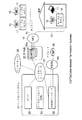
以下、図面を参照して本発明の実施の形態について説明する。図1は本実施形態に係わるケーブルモデム10が用いられるVoIPシステム構成を示すブロック図である。本実施形態におけるケーブルモデム10は、例えば家庭内などに設置されて使用されるもので、DOCSIS(Data Over System Interface Specification)プロトコルをサポートし、CATV網と接続して高速データサービス及びVoIPによる電話サービスを実現するものとする。VoIP対応のケーブルモデム10は、例えばEMTA(Embedded Media Terminal Adapter)とも呼ばれる。ケーブルモデム10がサポートする電話サービス機能としては、相手先(発信側)の電話番号を電話機上に表示するCallerID機能(情報表示機能)があるものとする。本実施形態では、ケーブルモデム10に接続される電話機12に依存せずに、電話機12がCallerID機能をサポートしていなくてもCallerID(相手先電話番号)を表示することができる機能を提供する。ケーブルモデム10は、電話機12を接続するためのアナログインタフェース、パーソナルコンピュータ14を接続するためのPCインタフェースなどが設けられている。また、ケーブルモデム10は、CATV網16と接続するためのCATV(Cable Television)ネットワークインタフェースが設けられている。ケーブルモデム10は、CATV網16を介してCATV網16に接続されている他のケーブルモデム17に接続されている。(このケーブルモデム17は、ケーブルモデム10と同じものである。)このケーブルモデム17には、電話機12が接続されている。従って、ケーブルモデム10とケーブルモデム17のVoIP機能を用いることにより、ケーブルモデム10に接続された電話機12とケーブルモデム17に接続された電話機12とは、相互に通話することができる。また、ケーブルモデム10は、CATV網16、HFC(Hybrid Fiber Coaxial)18、D−Hub(Distribution Hub)20に設けられているCMTS(Cable Modem Termination System)20aと接続されている。
【0010】
CMTS20aは、ケーブルモデム終端装置、ヘッドエンドモデム、ケーブルルータ等と呼ばれるもので、バックボーンネットワーク22を介してヘッドエンドシステム24、インターネット26と接続される。ヘッドエンドシステム24には、サーバ28、コールエージェント30、PSTNゲートウェイ32などが含まれる。サーバ28は、データサービスを提供するための制御を司るもので、各種プロトコル(例えば、DHCP(Dynamic Host Configuration Protocol)/TFTP(Trivial File Transfer Protocol)/SNMP(Simple Network Management Protocol))などによる通信制御を行う。コールエージェント30は、ケーブルモデム10を制御するもので、ケーブルモデム間あるいはケーブルモデム10とPSTNゲートウェイ32との間の通話チャネルの確立/解放等のシグナリング処理を実行する機能を持つ。PSTNゲートウェイ32は、公衆電話回線網(PSTN:Public Switched Telephone Network)34とデジタルネットワーク網との間でシグナリング及び音声データのアナログデジタル変換を行う。PSTNゲートウェイ32は、デジタルネットワーク網の電話機(CATV網16の電話機17、ケーブルモデム10に接続された電話機12)と公衆電話回線網34の電話機36との間で通話する場合にパケット交換と回線交換のプロトコル変換を行う。
【0011】
ケーブルモデム10に接続された電話機12には電話番号が、ケーブルモデム10にはIPアドレスが予め設定されている。電話機12において接続先の電話番号がダイヤルされると、ケーブルモデム10は、ダイヤル番号をコールエージェント30に通知する。コールエージェント30は、ケーブルモデム10から通知されたダイヤル番号をもとに、着信がケーブルモデム10であるかPSTNゲートウェイ32であるかを判断し、発信元のケーブルモデム10に着信先のケーブルモデム10あるいはPSTNゲートウェイ32のIPアドレスを通知する。発信元のケーブルモデム10は、コールエージェント30から通知された着信先のIPアドレスで直接、呼を確立してVoIPによる音声パケットが流れるようにして会話が可能な状態にする。
【0012】
図2は、図1中に示すVoIP対応のケーブルモデム10の詳細な構成を示すブロック図である。図2に示すように、ケーブルモデム10には、CPU40、チューナ41、コントローラ42、メモリ45、不揮発性メモリ46、データインタフェース47、DSP48、メモリ49、アナログインタフェース50、ディスプレイ51、及びボタン52が設けられている。
【0013】
CPU40は、メモリ45、不揮発性メモリ46に格納されたプログラムやデータに従い、ケーブルモデム10を構成する各部の制御を行なう。チューナ41は、コントローラ42による制御のもとで、DOCSIS準拠の下りのパケット信号(接続相手からの信号)を受信し、またDOCSIS準拠の上りのパケット信号(接続相手への信号)を出力する。コントローラ42は、DOCSISプロトコルを制御する機能を持っている。このDOCSISのプロトコルを制御する機能は、従来から実現されているものであり、その詳細な説明については省略する。また、コントローラ42には、CallerID機能(情報表示機能)を実現するためのCallerID検出プログラム43及びCallerID制御プログラム44とが設けられており、CallerID検出プログラム43によるCATV網16を介して受信したパケット信号からCallerID信号(Signaling Message)の検出、CallerID制御プログラム44による受信したCallerID信号に対するデータ登録/表示を実現している。メモリ45は、DOCSISプロトコル及びVoIPを制御するためのプログラムやデータを格納する。不揮発性メモリ46は、CallerID機能によって取得した相手先電話番号等のデータからなるCallerIDテーブル46aを格納する。データインタフェース47は、DOCSISによる高速データサービスを提供するためのパーソナルコンピュータ14を接続可能なインタフェースである。具体的には、10BASE−T、100BASE−T、USB(Universal Serial Bus)、HomePNA(Home Phoneline Networking Alliance)などによって実現される。DSP(Digital Signal Processor)48は、アナログインタフェース50を介して接続される電話機12を通じて、VoIPによって通話をする際の音声信号のアナログ/デジタル変換を行う。また、DSP48は、チューナ41を介して受信したデジタルのCallerID信号をアナログに変換して、アナログインタフェース50を通じて電話機12に送信する。電話機12がCallerID機能をサポートしている場合には、アナログのCallerID信号をもとにCallerIDを表示することができる。メモリ49は、DSP48によってアナログ/デジタル変換が実行される際の作業エリアとして利用される。アナログインタフェース50は、DSP48とアナログ電話機12とを接続するためのインタフェースである。ディスプレイ51は、CPU40の制御のもとで各種データを表示してユーザに対して提示するもので、CallerID機能が利用される場合にはCallerID(相手先電話番号)を表示する。ボタン52は、ユーザからの各種指示を入力するための複数のボタン群を含み、CallerID機能によってCallerIDをディスプレイ51において表示させる際に使用される上ボタン52a及び下ボタン52bが設けられている。上ボタン52a及び下ボタン52bは、不揮発性メモリ46に格納されたCallerIDテーブル46aに複数のCallerIDが登録されている場合に、任意のCallerIDを表示させるための表示切り替えを指示を入力する際に使用される。ダイヤルボタン52cは、ケーブルモデム10からディスプレイ51において表示されているCallerID先への発呼を指示するために用いられる。
【0014】
次に、本実施形態におけるケーブルモデム10の動作について説明する。
ケーブルモデム10は、チューナ41においてHFC18を介して得られる下り信号を選択する。ケーブルモデム10は、CPU40とコントローラ42とによって高速データサービスや電話サービスを制御し、データインタフェース47を介して接続されたパーソナルコンピュータ14に対してデータサービスを提供し、アナログインタフェース50を介して接続された電話機12に対して電話サービスを提供する。
【0015】
VoIPでは、アナログインタフェース50を介して接続された電話機12に対して電話サービスを提供する。電話サービスの1つであるCallerID機能では、コントローラ42においてCallerID検出プログラム43によってデジタルのCallerID信号を検出し、DSP48においてアナログ信号に変換してアナログインタフェース50を通じて電話機12に提供する。これにより、電話機12は、ケーブルモデム10から取得したアナログ信号のCallerID信号をもとにディスプレイにCallerIDを表示することができる。ここで、電話機12がCallerID機能をサポートしていない場合(あるいは電池切れなどによってディスプレイ表示ができない状態の場合)には、アナログ信号に変換されたCallerID信号は電話機12で無視されるため、ユーザはCallerIDを見ることが出来ない。
【0016】
一方、ケーブルモデム10は、電話機12とは関係なく、以下に説明するようにしてCallerID検出プログラム43により検出されたCallerID信号を、CallerID制御プログラム44により不揮発性メモリ46のCallerIDテーブル46aに登録すると共に、ディスプレイ51においてCallerIDを表示させることができる。
【0017】
次に、ケーブルモデム10によるCallerID機能の動作について、図3に示すフローチャートを参照しながら説明する。
ケーブルモデム10は、CallerID機能の実行が設定されている場合、CallerID検出プログラム43とCallerID制御プログラム44を起動する(ステップA1,B1)。
【0018】
コントローラ42は、CallerID検出プログラム43の制御により、チューナ41を通じてパケットを受信すると(ステップA2)、受信したパケットがシグナリングパケットであるかを判別する(ステップA3)。シグナリングパケットである場合(ステップA3、Yes)、シグナリングパケット内部に相手先電話番号を示すCallerID信号があるかを判別する(ステップA4)。受信したパケットがシグナリングパケットでない場合(ステップA3、No)、及びCallerID信号がない場合には(ステップA4、No)、同様にして受信したパケットに対するCallerID信号の検出を継続する(ステップA2〜A3)。受信したシグナリングパケットからCallerID信号が得られた場合にはCallerID制御プログラム44に通知して制御を渡す。
【0019】
CallerID制御プログラム44は、不揮発性メモリ46に格納されたCallerIDテーブル46aに既に予め決められた数のCallerIDか登録済みであるか、すなわちCallerIDテーブル46aが一杯であるかを確認する(ステップB2)。ここで、CallerIDテーブル46aに予め決められた数のCallerIDが登録済みであり一杯である場合には(ステップB2、Yes)、CallerIDテーブル46aに登録された一番古いCallerIDに新しく受信したCallerIDを上書きする(ステップB3)。また、CallerIDテーブル46aに余裕がある場合には(ステップB2、No)、テーブルのエントリを追加し、新しく受信したCallerIDを書き込む(ステップB4)。図4には、CallerIDテーブル46aに複数のCallerIDが登録されている状態の一例を示している。
【0020】
CallerID制御プログラム44は、不揮発性メモリ46に格納した新たに受信したCallerIDを登録したCallerIDテーブル46aをメモリ45に記憶させ(ステップB5)、これをもとにディスプレイ51において受信したCallerIDを表示させる(ステップB6)。図5(a)には、ディスプレイ51において新たに受信したCallerID「○○○○○○5678」が表示されている状態を示している。これにより、電話機12がCallerID機能をサポートしていなくても、ケーブルモデム10に設けられたディスプレイ51においてCallerID(相手先電話番号)を確認することができる。
【0021】
なお、CallerID検出プログラム43により検出されたCallerIDは、DSP48によりアナログ信号に変換されて、アナログインタフェース50を通じて電話機12に通知される。電話機12がCallerID機能をサポートしている場合には、電話機12のディスプレイにおいてもCallerIDが表示されて確認が可能である。
【0022】
また、CallerIDテーブル46aに登録されたCallerIDをボタン52の上ボタン52a,下ボタン52bを押下することで任意にを切り替えて表示させることができる。図6には、ディスプレイ51に表示されたCallerIDに対する操作処理のフローチャートを示している。
【0023】
ケーブルモデム10では、例えばボタン52中の図示せぬボタンの操作によって、過去に受信してCallerIDテーブル46aに登録されているCallerIDを任意に表示させることができる。
【0024】
CallerIDがディスプレイ51において表示された状態で上ボタン52aが押された場合(ステップB7)、現在表示対象となっているCallerIDのCallerIDテーブル46aにおける1段上のエントリのCallerIDを表示対象に変更する(ステップB8)。ここで、表示対象としたエントリにCallerIDが登録されていた場合には(ステップB11、Yes)、そのCallerIDをディスプレイ51において表示する。一方、表示対象にしたエントリにCallerIDが登録されていない場合には(ステップB11、No)、例えば「No data」の文字列をディスプレイ51において表示して、該当エントリにCallerIDが登録されていないことを提示する(ステップB13)。図5(b)には、図5(a)のようにCallerIDが表示されている状態で上ボタン52aが押下された場合に表示されるCallerIDの一例を示している。すなわち、図4に示すエントリ2のCallerID「○○○○○○5678」の1段上のエントリであるエントリ1のCallerID「××××××1234」が表示されている。
【0025】
同様にして、下ボタン52bが押下された場合(ステップB9)、現在表示対象となっているCallerIDのCallerIDテーブル46aにおける1段下のエントリのCallerIDを表示対象に変更する(ステップB9)。ここで、表示対象としたエントリにCallerIDが登録されていた場合には(ステップB11、Yes)、そのCallerIDをディスプレイ51において表示する。一方、表示対象にしたエントリにCallerIDが登録されていない場合には(ステップB11、No)、例えば「No data」の文字列をディスプレイ51において表示して、該当エントリにCallerIDが登録されていないことを提示する(ステップB13)。図5(c)には、図5(a)のようにCallerIDが表示されている状態で下ボタン52bが押下された場合に表示されるCallerIDの一例を示している。すなわち、図4に示すCallerID「○○○○○○5678」の1段下のエントリ3のCallerID「△△△△△△9012」が表示されている。
【0026】
こうして、CallerIDテーブル46aに登録された過去に受信したCallerIDを含めて、上ボタン52a、下ボタン52bに対する操作によって任意に表示対象を切り替えてディスプレイ51において表示させることができる。
【0027】
さらに、本実施形態におけるケーブルモデム10では、ディスプレイ51において任意のCallerIDを表示させた状態でダイヤルボタン52cを押下することで、該当するCallerIDを接続先として発呼(ダイアリング)する接続処理を実行させることができる。
【0028】
すなわち、CallerIDが表示された状態でダイヤルボタン52cが押された場合(ステップB14)、アナログインタフェース50を通じて電話機12がオフフックされて通話可能な状態となっているかを確認する(ステップB15)。オフフックされていなかった場合、所定時間が経過するまで、電話機12がオフフックされたことが通知するまで待つ(ステップB16のNo,B15)。所定時間が経過しても電話機12がオフフックされない場合には(ステップB16、Yes)、通話ができないので、現在表示中のCallerIDに対する発呼を中止する。
【0029】
一方、所定時間内に電話機12がオフフックされたことが通知されると、コントローラ42は、ユーザがダイアルする番号の代わりに、現在表示中のCallerIDに対応する相手を接続先としてコールエージェント30へ通知し、接続処理を実行する(ステップB17)。
【0030】
これにより、電話機12がCallerID機能をサポートしていない場合であっても、ケーブルモデム10が提供するCallerID機能を利用して、接続相手のCallerIDをディスプレイ51に表示させてダイヤルボタン52cを押下することで、簡単にCallerIDを受信したことのある相手との接続が可能となる。
【0031】
このようにして、デジタル化されたCallerID信号をケーブルモデム10において検出し、この検出したCallerIDをケーブルモデム10に設けたディスプレイ51に表示するので、電話機12に依存せずにCallerIDサービスを利用することが可能となる。すなわち、電話機12がCallerID機能をサポートしていない場合や、電話機12がCallerID機能をサポートしていたとしても、電池切れなどによってディスプレイ表示できない状態にある場合であっても、CallerIDサービスを利用することができる。
【0032】
なお、前述した説明では、相手先(発信側)から受信した信号からCallerID信号を検出してCallerID(相手先電話番号)を表示する場合についてのみ説明しているが、相手先から受信される信号から検出可能な他の情報を表示するようにしても良い。他の情報としては、日時、相手先で任意に付加された属性情報などがある。この場合も電話機12に依存することなくケーブルモデム10において各種情報をディスプレイ51に表示してユーザに提示することができる。
【0033】
また、図2に示す構成では、CallerID検出プログラム43とCallerID制御プログラム44がコントローラ42に付随して設けられているものとして説明しているが、メモリ45に格納されてCPU40により実行されることで、CallerID信号の検出、CallerIDに対する表示制御が行われる構成としても良い。この場合、CallerID検出プログラム43とCallerID制御プログラム44は、コンピュータに実行させることのできるプログラムとして、例えば磁気ディスク(フレキシブルディスク、ハードディスク等)、光ディスク(CD−ROM、DVD等)、半導体メモリなどの記録媒体に書き込んで各種装置に提供することができる。また、通信媒体により伝送して各種装置に提供することも可能である。本実施形態におけるケーブルモデム10を実現する装置(コンピュータ)は、記録媒体に記録されたプログラムを読み込み、または通信媒体を介してプログラムを受信し、このプログラムによって動作が制御されることにより、上述した処理を実行する。
【0034】
また、本願発明は、前述した実施形態に限定されるものではなく、実施段階ではその要旨を逸脱しない範囲で種々に変形することが可能である。更に、前記実施形態には種々の段階の発明が含まれており、開示される複数の構成要件における適宜な組み合わせにより種々の発明が抽出され得る。例えば、実施形態に示される全構成要件から幾つかの構成要件が削除されても効果が得られる場合には、この構成要件が削除された構成が発明として抽出され得る。
【0035】
【発明の効果】
以上詳述したように本発明によれば、ケーブルモデムにおいてデジタル化されたCallerID信号を検出し、この検出したCallerIDをケーブルモデムに設けたディスプレイに表示するので、電話機に依存せずにCallerIDサービスを利用することが可能となる。
【図面の簡単な説明】
【図1】本実施形態に係わるケーブルモデム10が用いられるVoIPシステム構成を示すブロック図。
【図2】図1中に示すVoIP対応のケーブルモデム10の詳細な構成を示すブロック図。
【図3】ケーブルモデム10によるCallerID機能の動作について説明するためのフローチャート。
【図4】CallerIDテーブル46aに複数のCallerIDが登録されている状態の一例を示す図。
【図5】CallerIDが表示されているディスプレイの表示例を示す図。
【図6】ディスプレイ51に表示されたCallerIDに対する操作処理を説明するためのフローチャート。
【符号の説明】
10,17…ケーブルモデム
12,36…電話機
14…パーソナルコンピュータ(PC)
16…CATV網
18…HFC
20…D−Hub
20a…CMTS
22…バックボーンネットワーク
24…ヘッドエンドシステム
26…インターネット
28…サーバ
30…コールエージェント(CA)
32…PSTNゲートウェイ
34…公衆電話回線網(PSTN)
40…CPU
41…チューナ
42…コントローラ
43…CallerID検出プログラム
44…CallerID制御プログラム
45…メモリ
46…不揮発性メモリ
46a…CallerIDテーブル
47…データインタフェース
48…DSP(Digital Signal Processor)
49…メモリ
50…アナログインタフェース
51…ディスプレイ
52…ボタン[0001]
BACKGROUND OF THE INVENTION
The present invention relates to a VoIP (Voice over Internet Protocol) compatible cable modem used by connecting to a CATV (Cable Television) network, and more particularly to a cable modem having a CallerID display function.
[0002]
[Prior art]
With the spread of the Internet, the demand for home data communication services is increasing. Under these circumstances, the establishment of communication protocol standardization and equipment qualification test standards for enabling IP (internet protocol) communication on the CATV network called DOCSIS (Data Over System Interface Specification). The penetration rate of cable modems is increasing rapidly due to improved compatibility and lower prices. High-speed data communication of several Mbps is possible in each home, and use of various applications such as video distribution and voice calls is expected.
[0003]
In recent years, it has become possible to provide a VoIP telephone service in addition to a high-speed data service by installing a VoIP compatible cable modem in each home. Cable modems support various telephone service functions in addition to general telephone services. As this telephone service function, there is a Caller ID (IDentification) function for displaying the telephone number of the other party (calling side) on the telephone. When using the CallerID function, the telephone side needs to support this function.
[0004]
When the cable modem receives a digitized CallerID signal (Signaling Message) indicating the telephone number of the other party (calling side), the cable modem converts this signal into an analog signal and transmits it to the telephone with the CallerID function through the analog interface. The telephone displays the Caller ID (destination telephone number) on the display based on the signal from the cable modem.
[0005]
[Problems to be solved by the invention]
As described above, conventionally, the Caller ID can be displayed by converting the Caller ID signal digitized by the cable modem into an analog signal and transmitting the analog signal to a telephone that supports the Caller ID function.
[0006]
That is, whether or not the Caller ID function can be used depends on whether or not the telephone supports the Caller ID function, and cannot be used when the telephone ID function is not supported. Further, even if the telephone supports the Caller ID function, the Caller ID function cannot be used when the display cannot be displayed due to battery exhaustion or the like.
[0007]
The present invention has been made in consideration of the above-described circumstances, and an object of the present invention is to provide a cable modem that can use the Caller ID function without depending on a telephone.
[0008]
[Means for Solving the Problems]
The present invention Phone is connected In a VoIP compatible cable modem, Via communication network Detecting means for detecting information of the connection partner from the received signal; Providing means for providing information detected by the detecting means to the telephone; table storing means for registering a plurality of pieces of information detected by the detecting means; Display means for displaying information detected by the detection means; Switching means for switching information to be displayed by the display means among a plurality of pieces of information stored by the table storage means, and input means for inputting a connection request with a connection partner corresponding to the information displayed by the display means And a confirmation means for confirming whether the telephone is ready for a call before a predetermined time elapses when a connection request is input by the input means; and a state in which the telephone can be communicated by the confirmation means When the confirmation is made, the connection means for making a call to the connection partner corresponding to the information displayed by the display means, and the telephone set before the predetermined time elapses by the confirmation means A canceling means for canceling a call to the connection partner when it is not confirmed that a call can be made; It is characterized by comprising.
[0009]
DETAILED DESCRIPTION OF THE INVENTION
Embodiments of the present invention will be described below with reference to the drawings. FIG. 1 is a block diagram showing a VoIP system configuration in which a
[0010]
The CMTS 20 a is called a cable modem terminator, a head end modem, a cable router or the like, and is connected to the head end system 24 and the Internet 26 via the
[0011]
The
[0012]
FIG. 2 is a block diagram showing a detailed configuration of the VoIP
[0013]
The
[0014]
Next, the operation of the
The
[0015]
In VoIP, a telephone service is provided to the
[0016]
On the other hand, the
[0017]
Next, the operation of the Caller ID function by the
When the execution of the CallerID function is set, the
[0018]
When receiving a packet through the
[0019]
The Caller
[0020]
The Caller
[0021]
The Caller ID detected by the Caller
[0022]
Further, the Caller ID registered in the Caller ID table 46a can be arbitrarily switched and displayed by pressing the
[0023]
In the
[0024]
When the
[0025]
Similarly, when the
[0026]
In this way, including the previously received CallerID registered in the CallerID table 46a, the display target can be arbitrarily switched and displayed on the
[0027]
Furthermore, in the
[0028]
That is, when the
[0029]
On the other hand, when notified that the
[0030]
Thus, even when the
[0031]
In this way, the digitized CallerID signal is detected by the
[0032]
In the above description, only the case where the Caller ID signal is detected from the signal received from the other party (calling side) and the Caller ID (the other party telephone number) is displayed is described. However, the signal received from the other party Other information that can be detected from the image may be displayed. Other information includes date and time, attribute information arbitrarily added by the other party, and the like. Also in this case, various information can be displayed on the
[0033]
Further, in the configuration shown in FIG. 2, it is described that the Caller
[0034]
The present invention is not limited to the above-described embodiments, and various modifications can be made without departing from the scope of the invention at the stage of implementation. Further, the embodiments include inventions at various stages, and various inventions can be extracted by appropriately combining a plurality of disclosed constituent elements. For example, when the effect can be obtained even if several constituent requirements are deleted from all the constituent requirements shown in the embodiment, a configuration from which the constituent requirements are deleted can be extracted as an invention.
[0035]
【The invention's effect】
As described above in detail, according to the present invention, the digitized Caller ID signal is detected in the cable modem, and the detected Caller ID is displayed on the display provided in the cable modem, so that the Caller ID service can be performed without depending on the telephone. It can be used.
[Brief description of the drawings]
FIG. 1 is a block diagram showing a VoIP system configuration in which a
FIG. 2 is a block diagram showing a detailed configuration of the VoIP
FIG. 3 is a flowchart for explaining the operation of the Caller ID function by the
FIG. 4 is a diagram showing an example of a state in which a plurality of Caller IDs are registered in a Caller ID table 46a.
FIG. 5 is a diagram showing a display example of a display on which CallerID is displayed.
FIG. 6 is a flowchart for explaining an operation process for CallerID displayed on the
[Explanation of symbols]
10, 17 ... cable modem
12, 36 ... Telephone
14 ... Personal computer (PC)
16 ... CATV network
18 ... HFC
20 ... D-Hub
20a ... CMTS
22 ... Backbone network
24 ... Headend system
26 ... Internet
28 ... Server
30 ... Call Agent (CA)
32 ... PSTN gateway
34 ... Public telephone network (PSTN)
40 ... CPU
41 ... Tuner
42 ... Controller
43 ... CallerID detection program
44 ... CallerID control program
45 ... Memory
46 ... Non-volatile memory
46a ... CallerID table
47 ... Data interface
48 ... DSP (Digital Signal Processor)
49 ... Memory
50 ... Analog interface
51 ... Display
52 ... button
Claims (3)
通信網を介して受信した信号から接続相手の情報を検出する検出手段と、
前記検出手段により検出された情報を前記電話機に提供する提供手段と、
前記検出手段によって検出された情報を複数登録しておくためのテーブル格納手段と、
前記検出手段によって検出された情報を表示する表示手段と、
前記テーブル格納手段によって格納された複数の情報のうち前記表示手段によって表示対象となる情報を切り替える切り替え手段と、
前記表示手段により表示された情報に対応する接続相手との接続要求を入力する入力手段と、
前記入力手段により接続要求が入力された場合に前記電話機が所定時間が経過するまでに通話可能な状態となっているかを確認する確認手段と、
前記確認手段により前記電話機が通話可能な状態となっていることが確認された場合に、前記表示手段により表示された情報に対応する前記接続相手に対する発呼を実行する接続手段と、
前記確認手段により所定時間が経過するまでに前記電話機が通話可能な状態となったことが確認されなかった場合に前記接続相手に対する発呼を中止する中止手段と
を具備したことを特徴とするケーブルモデム。 In a VoIP (Voice over Internet Protocol) compatible cable modem to which the telephone is connected ,
Detecting means for detecting information of a connection partner from a signal received via a communication network ;
Providing means for providing information detected by the detecting means to the telephone;
Table storage means for registering a plurality of pieces of information detected by the detection means;
Display means for displaying information detected by the detection means;
Switching means for switching information to be displayed by the display means among the plurality of information stored by the table storage means;
An input means for inputting a connection request with a connection partner corresponding to the information displayed by the display means;
Confirmation means for confirming whether the telephone is ready for a call before a predetermined time elapses when a connection request is input by the input means;
Connection means for making a call to the connection partner corresponding to the information displayed by the display means when it is confirmed by the confirmation means that the telephone is in a callable state;
A canceling means for canceling a call to the connection partner when the confirmation means does not confirm that the telephone is ready for a call before a predetermined time elapses. Characteristic cable modem.
コンピュータを、
通信網を介して受信した信号から接続相手の情報を検出する検出手段と、
前記検出手段により検出された情報を前記電話機に提供する提供手段と、
前記検出手段によって検出された情報を複数登録しておくためのテーブル格納手段と、
前記検出手段によって検出された情報を表示する表示手段と、
前記テーブル格納手段によって格納された複数の情報のうち前記表示手段によって表示対象となる情報を切り替える切り替え手段と、
前記表示手段により表示された情報に対応する接続相手との接続要求を入力する入力手段と、
前記入力手段により接続要求が入力された場合に前記電話機が所定時間が経過するまでに通話可能な状態となっているかを確認する確認手段と、
前記確認手段により前記電話機が通話可能な状態となっていることが確認された場合に、前記表示手段により表示された情報に対応する前記接続相手に対する発呼を実行する接続手段と、
前記確認手段により所定時間が経過するまでに前記電話機が通話可能な状態となったことが確認されなかった場合に前記接続相手に対する発呼を中止する中止手段として機能させるための情報表示制御プログラム。An information display control program for controlling a computer that realizes a VoIP compatible cable modem to which a telephone is connected ,
Computer
Detecting means for detecting information of a connection partner from a signal received via a communication network ;
Providing means for providing information detected by the detecting means to the telephone;
Table storage means for registering a plurality of pieces of information detected by the detection means;
Display means for displaying information detected by the detection means;
Switching means for switching information to be displayed by the display means among the plurality of information stored by the table storage means;
An input means for inputting a connection request with a connection partner corresponding to the information displayed by the display means;
Confirmation means for confirming whether the telephone is ready for a call before a predetermined time elapses when a connection request is input by the input means;
Connection means for making a call to the connection partner corresponding to the information displayed by the display means when it is confirmed by the confirmation means that the telephone is in a callable state;
An information display control program for causing the confirmation unit to function as a canceling unit for canceling a call to the connection partner when it is not confirmed that the telephone is ready for a call before a predetermined time elapses .
Priority Applications (3)
| Application Number | Priority Date | Filing Date | Title |
|---|---|---|---|
| JP2002023922A JP3655246B2 (en) | 2002-01-31 | 2002-01-31 | Cable modem, information display control program |
| US10/353,963 US20030145332A1 (en) | 2002-01-31 | 2003-01-30 | VoIP (voice over internet protocol)-compliant cable modem |
| EP03002081A EP1333617A3 (en) | 2002-01-31 | 2003-01-30 | VoIP (Voice over Internet Protocol) -compliant cable modem |
Applications Claiming Priority (1)
| Application Number | Priority Date | Filing Date | Title |
|---|---|---|---|
| JP2002023922A JP3655246B2 (en) | 2002-01-31 | 2002-01-31 | Cable modem, information display control program |
Publications (2)
| Publication Number | Publication Date |
|---|---|
| JP2003224679A JP2003224679A (en) | 2003-08-08 |
| JP3655246B2 true JP3655246B2 (en) | 2005-06-02 |
Family
ID=19192260
Family Applications (1)
| Application Number | Title | Priority Date | Filing Date |
|---|---|---|---|
| JP2002023922A Expired - Fee Related JP3655246B2 (en) | 2002-01-31 | 2002-01-31 | Cable modem, information display control program |
Country Status (3)
| Country | Link |
|---|---|
| US (1) | US20030145332A1 (en) |
| EP (1) | EP1333617A3 (en) |
| JP (1) | JP3655246B2 (en) |
Families Citing this family (10)
| Publication number | Priority date | Publication date | Assignee | Title |
|---|---|---|---|---|
| US20030202462A1 (en) * | 2002-04-29 | 2003-10-30 | Smith David B. | Method and apparatus for fail over protection in a voice over internet communication system |
| US7460523B2 (en) * | 2003-09-08 | 2008-12-02 | Bradley Richard Ree | Client-server architecture for the delivery of broadband services |
| US20060221947A1 (en) * | 2005-03-30 | 2006-10-05 | Baker Mark C | Multiple IP identities for end user telephony devices |
| JP2007006009A (en) * | 2005-06-22 | 2007-01-11 | Adc Technology Kk | Telephone adapter |
| US20070124205A1 (en) * | 2005-09-14 | 2007-05-31 | Xg Technology, Llc | Enhanced modem for direct advertising information via an LCD screen |
| TWI307236B (en) * | 2006-03-03 | 2009-03-01 | Hon Hai Prec Ind Co Ltd | Voip modem and method for detecting voip services |
| CA2659436A1 (en) * | 2006-08-11 | 2008-02-14 | Xg Technology, Inc. | Enhanced modem for direct advertising information via an lcd screen |
| CN101640596B (en) * | 2008-07-31 | 2012-05-23 | 鸿富锦精密工业(深圳)有限公司 | Modulator-demodulator and configuration method thereof |
| TWI510025B (en) * | 2012-07-24 | 2015-11-21 | Nec Corp | Communication systems and methods and programs |
| CN105846863B (en) * | 2016-05-31 | 2019-07-05 | 青岛海信电器股份有限公司 | A kind of operating method and equipment based on bluetooth |
Family Cites Families (5)
| Publication number | Priority date | Publication date | Assignee | Title |
|---|---|---|---|---|
| JPH10150501A (en) * | 1996-11-18 | 1998-06-02 | Nippon Telecom Kk | Terminal equipment for catv terminal equipment |
| US6711160B2 (en) * | 1998-03-31 | 2004-03-23 | International Business Machines Corporation | Packet network telephone interface system for POTS |
| US6209025B1 (en) * | 1998-11-09 | 2001-03-27 | John C Bellamy | Integrated video system |
| US6785301B1 (en) * | 2000-06-29 | 2004-08-31 | Cisco Technology, Inc. | Method and apparatus for conducting call waiting-caller identification in a packet switched network |
| US7113503B1 (en) * | 2001-12-18 | 2006-09-26 | At&T Corp. | Intelligent network interface device for caller identification multicasting |
-
2002
- 2002-01-31 JP JP2002023922A patent/JP3655246B2/en not_active Expired - Fee Related
-
2003
- 2003-01-30 US US10/353,963 patent/US20030145332A1/en not_active Abandoned
- 2003-01-30 EP EP03002081A patent/EP1333617A3/en not_active Withdrawn
Also Published As
| Publication number | Publication date |
|---|---|
| EP1333617A3 (en) | 2005-11-02 |
| EP1333617A2 (en) | 2003-08-06 |
| US20030145332A1 (en) | 2003-07-31 |
| JP2003224679A (en) | 2003-08-08 |
Similar Documents
| Publication | Publication Date | Title |
|---|---|---|
| US6700955B1 (en) | System and method for remote management of a DSL device | |
| US7106726B2 (en) | Internet switch box, system and method for internet telephony | |
| EP1816843A1 (en) | Set top box supporting bridging between a packet switched network and the public switched telephone network | |
| US9749586B2 (en) | Integration of home entertainment devices with a software client for telephony | |
| US20020162116A1 (en) | VoIP telephony peripheral | |
| US20070183401A1 (en) | Set top box supporting selective local call termination and call bridging | |
| JP3655246B2 (en) | Cable modem, information display control program | |
| JP2005218120A (en) | VoIP TERMINAL, AND CALL BACKUP METHOD OF VoIP TERMINAL | |
| JP3758808B2 (en) | Communication terminal and communication method | |
| EP2074750B1 (en) | Embedded media terminal adapter (emta) endpoint redirect mode | |
| US8526583B2 (en) | Media terminal adapter (MTA) local ringback option | |
| JP2005039540A (en) | Television receiver | |
| US20100008264A1 (en) | Method and apparatus for facilitating installation of packet-switched telephony equipment on a subscriber premises | |
| US7227933B1 (en) | System and method for remote management of a DSL device | |
| JP2003198725A (en) | Cable modem, and protocol conversion processing program | |
| JP2004135147A (en) | Cable terminal, server device, and initial setup method | |
| US7609286B2 (en) | Method and apparatus for video conferencing | |
| JP4391362B2 (en) | Image communication device | |
| JP5428074B2 (en) | Message transmission device, message transmission system, message transmission method, and program for causing computer to function as message transmission device | |
| JP2003348252A (en) | Cable modem, speaking information recording apparatus and method, and speaking information management program | |
| TWI262704B (en) | VoIP terminal with PSTN connection supported | |
| JP2004135060A (en) | Cable modem and informing method for voice mail | |
| JP2005057365A (en) | Cable modem, connection control method, and connection control program | |
| JP3882801B2 (en) | IP telephone system, server device and router control method | |
| JP4193671B2 (en) | Heterogeneous network line accommodation apparatus, information notification program, and recording medium |
Legal Events
| Date | Code | Title | Description |
|---|---|---|---|
| A977 | Report on retrieval |
Free format text: JAPANESE INTERMEDIATE CODE: A971007 Effective date: 20040728 |
|
| A131 | Notification of reasons for refusal |
Free format text: JAPANESE INTERMEDIATE CODE: A131 Effective date: 20040803 |
|
| A521 | Written amendment |
Free format text: JAPANESE INTERMEDIATE CODE: A523 Effective date: 20040929 |
|
| TRDD | Decision of grant or rejection written | ||
| A01 | Written decision to grant a patent or to grant a registration (utility model) |
Free format text: JAPANESE INTERMEDIATE CODE: A01 Effective date: 20050222 |
|
| A61 | First payment of annual fees (during grant procedure) |
Free format text: JAPANESE INTERMEDIATE CODE: A61 Effective date: 20050302 |
|
| LAPS | Cancellation because of no payment of annual fees |