JP3653746B2 - Electronic clock - Google Patents
Electronic clock Download PDFInfo
- Publication number
- JP3653746B2 JP3653746B2 JP14609994A JP14609994A JP3653746B2 JP 3653746 B2 JP3653746 B2 JP 3653746B2 JP 14609994 A JP14609994 A JP 14609994A JP 14609994 A JP14609994 A JP 14609994A JP 3653746 B2 JP3653746 B2 JP 3653746B2
- Authority
- JP
- Japan
- Prior art keywords
- atmospheric pressure
- data
- sensor
- needle
- environmental data
- Prior art date
- Legal status (The legal status is an assumption and is not a legal conclusion. Google has not performed a legal analysis and makes no representation as to the accuracy of the status listed.)
- Expired - Lifetime
Links
Images


Classifications
-
- G—PHYSICS
- G04—HOROLOGY
- G04G—ELECTRONIC TIME-PIECES
- G04G21/00—Input or output devices integrated in time-pieces
- G04G21/02—Detectors of external physical values, e.g. temperature
-
- G—PHYSICS
- G04—HOROLOGY
- G04C—ELECTROMECHANICAL CLOCKS OR WATCHES
- G04C3/00—Electromechanical clocks or watches independent of other time-pieces and in which the movement is maintained by electric means
- G04C3/008—Mounting, assembling of components
-
- G—PHYSICS
- G04—HOROLOGY
- G04C—ELECTROMECHANICAL CLOCKS OR WATCHES
- G04C3/00—Electromechanical clocks or watches independent of other time-pieces and in which the movement is maintained by electric means
- G04C3/14—Electromechanical clocks or watches independent of other time-pieces and in which the movement is maintained by electric means incorporating a stepping motor
- G04C3/146—Electromechanical clocks or watches independent of other time-pieces and in which the movement is maintained by electric means incorporating a stepping motor incorporating two or more stepping motors or rotors
Description
【0001】
【産業上の利用分野】
本発明は、電子時計に関し、さらに詳しくは、センサなどを内蔵した多機能電子時計に関するものである。
【0002】
【従来の技術】
従来のセンサ付き多機能電子時計では、実開昭61−154585号公報、または特開平4−64085号公報に記載されているように、時刻表示面とセンサとを重ならないようにする目的に、外装ケースの外周部に突出部を設け、そこにセンサを内蔵させている。
【0003】
また、実開平4−43238号公報には、センサとして圧力センサを電子時計に内蔵させて気圧計や高度計としての機能を付加し、さらに天候を表示するものも商品化されている。
【0004】
さらに、特開昭60−260883号公報には、電子時計の電池寿命を延ばす目的に、各種の検出パルスを用いた補正駆動方式を採用することが開示されている。
【0005】
【発明が解決しようとする課題】
しかしながら、従来の電子時計では、新たな機能を追加すると、以下に掲げるように、追加した機能の価値を損なうほどのマイナス面があるという問題点がある。
【0006】
まず、第1に、新たな機能を追加するにあたって、指針式でないので、表示を確認しにくい。
【0007】
第2に、気圧値を測定可能にした多機能電子時計では、その測定結果から相対高度や海面校正した気圧値を求めようとすると、補正のための演算が必要であるため、多数の操作ボタンを配置する必要があるとともに、その操作が極めて複雑になる。
【0012】
以上の問題点に鑑みて、本発明の課題は、新たな機能を追加するにあたって、構造上のマイナス面を最小限に抑えた電子時計を提供することにある。たとえば、複雑な構造や操作を必要とすることなく、新たな機能として、気圧から高度の読みとりができ、しかも、気圧の海面更生を行なえるセンサ付きの電子時計を提供することを課題とする。また、新たな機能として、簡単な構成で気圧値などの環境データの変化量を表示可能な電子時計を提供する。
【0013】
【課題を解決するための手段】
上記課題を解決するために、本発明の電子時計では、
気圧値、湿度、温度などの環境データを測定するセンサと、
前記センサの測定結果を表示する複数の環境データ表示用指針、前記センサの測定結果に基づいて測定値の変化を検出する変化量検出手段、及び前記変化量検出手段の検出結果に基づいて前記環境データの変化量を表示する変化量表示用指針とを備えた環境データ表示手段と、
時刻を指針で表示する時刻表示手段と、
前記センサ、前記環境データ表示手段、および前記時刻表示手段の駆動源となる電池と、
前記センサ、前記環境データ表示手段、および前記時刻表示手段を制御するICとを有する電子時計において、
前記時刻表示手段は、第 1 のステップモータによって駆動され、
前記環境データ表示用指針の内最小単位で表示される第1指針および前記第1指針が取りつけられた番車からの減速輪列を介して表示される前記変化量表示用指針は、前記第2のステップモータによって駆動され、
前記環境データ表示用指針の内前記最小単位以外の計測単位で表示される指針は、第3のステップモータによって駆動される
ことを特徴とする。
【0014】
また、本発明の電子時計では、前記環境データ表示手段は、前記環境データの最大値または最小値のいずれかを含む特定データを記憶しておく特定データ記憶手段と、この記憶手段に記憶されている特定データを表示する特定データ表示手段と、この特定データ表示手段が前記特定データ記憶手段に記憶されている特定データを表示する直前に前記センサに環境データを測定させ、その測定結果に基づいて表示すべき特定データを更新する特定データ更新手段とを有することを特徴する。
【0015】
さらに、本発明の電子時計では、前記センサの測定結果と表示とのずれを校正するための校正手段とを有し、前記校正手段は、校正可能なモードに入るための操作を開始してから、モードに入るまでの間に、前記センサに環境データを測定させ、その測定結果を前記環境データ表示手段に表示させることを特徴とする。
【0016】
また、本発明の電子時計では、前記校正手段は、校正動作を開始した直後にその旨の報知音を発生する報知音発生手段を有することを特徴とする。
【0017】
また、本発明の電子時計では、前記環境データ表示手段は、前記センサの測定結果のうちから異常データの有無を検出する異常データ検出手段と、前記異常データ検出手段による検出結果に基づいて、前記センサの測定結果から前記異常データを除いたデータに基づいて前記環境データの変化量を演算するデータ手段とを有することを特徴とする。
【0032】
本発明のいずれの形態においても、環境データとして、湿度や温度などを測定してそれを表示することができ、特に、気圧や水圧などの圧力値を測定してそれを表示した場合には、アウトドアライフを楽しむ者にとって便利である。
【0033】
【実施例】
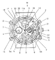
図1は、本例の多機能電子時計の要部の外観を示す平面図である。
【0034】
(全体構成および機能の概略説明)
この図において、本例のセンサ付き多機能電子時計Wには、センター指針としての時針1および分針2が取り付けられているとともに、九時を示す方向には、副針としての秒針3および二十四時針4が取り付けられている。文字板5には、時針1に対応する位置に十二時間制の目盛り5aが形成され、五時を示す方向と四時を示す方向との間には、カレンダーを表示する日車6を透視するための窓5bが形成されている。
【0035】
文字板5の三時を示す方向には、月齢を表示するための月齢車7を透視するための窓5cも形成され、時針1に連動する月齢車7により月の満ち欠けを表示している。
【0036】
文字板5の六時を示す方向には、アラーム時刻を表示するアラーム時針8およびアラーム分針9が配置されており、予め設定されたアラーム時刻と、現在の時刻とが一致したときにアラーム音が20秒間発生するようになっている。アラーム時刻の設定は、四時を示す方向に設けられた四時龍頭15を操作することにより行なうようになっている。
【0037】
たとえば、四時龍頭15を通常位置に押し込んだ状態では、いわゆるワンタッチ・アラームモードであり、アラーム音を1回発生すると、アラームセットが解除される。この状態では、八時方向にある八時ボタン14を押すたびにアラーム分針9、およびアラーム時針8が1分単位で運針されるので、アラーム時刻を所定の時刻に設定できる。従って、最大で12時間のアラーム設定が可能である。また、八時ボタン14を押し続けると、アラーム分針9およびアラーム時針8は、加速的に連続回転するので、アラーム時刻を短時間で設定できる。
【0038】
四時龍頭15を一段階引き出した状態では、いわゆるデイリーアラームモードになり、設定時刻になると、アラーム音が毎日12時間サイクルで2回発生する。この状態でも、八時ボタン14を押すと、アラーム分針9およびアラーム時針8が1分単位で回転するので、アラーム時刻を設定できる。また、八時ボタン14を押し続けると、アラーム分針9およびアラーム時針8は、加速的に連続して回転するので、アラーム時刻を短時間で設定できる。
【0039】
四時龍頭15を二段階引き出した状態では、時差修正モードになり、八時ボタン14を押す度に、アラーム分針9およびアラーム時針8が1時間単位で運針されるので、アラーム設定時刻を時差修正することができる。この状態で、四時龍頭15を回転させると、時針1を単独で回転させることができ、この方法でも、時差修正を行なうことができる。
【0040】
なお、アラーム時針8およびアラーム分針9は、ワンタッチ・アラームモードの場合には、アラーム音を発生させた以降、12時間制で時刻を1分ステップで表示する。この場合の動作は、時針1、および分針2などとは独立している。従って、アラーム時針8およびアラーム分針9の時刻合わせを行なう場合がある。この場合には、小秒針3が0秒位置にきたときに、三時龍頭16を二段階引出した後、八時ボタン14を押して時刻を合わせ、しかる後に、時報に合わせて三時龍頭16を通常状態にまで押し込む。また、三時龍頭16を二段階引き出した状態で三時龍頭16を回転させることによっても、時刻修正が可能である。なお、三時龍頭16を引き出す度に報知音を発生するようにすることにより、ユーザの使い勝手を高めてある。
【0041】
また、三時龍頭16を一段階引き出した状態で、三時龍頭16を回転させることによって、カレンダー修正と月齢修正とが可能である。さらに、三時龍頭16は、通常位置にあるときには、後述の気圧表示機能を切り換えるスイッチとしての機能も有する。
【0042】
本例のセンサ付き多機能電子時計において、センター位置には、1ステップで2hPaを表示する気圧針11が設けられ、文字板5の周囲に取り付けられたダイヤルリング17には、気圧目盛り18が付されている。文字板5の十二時を示す方向には、気圧の最小単位を示す小気圧針10が設けられ、その周囲には小気圧目盛り11aが印刷されている。通常の携帯時には、三時龍頭16を通常状態に押し込んでおけば、後述する気圧センサにより、気圧値が10分間に1回測定され、測定されたデータは、アナログ・デジタル変換された後、小気圧針10および気圧針11で表示されるようになっている。また、三時龍頭16を通常状態に押し込んだ状態で、二時を示す方向に設けられた二時ボタン12を押すことによって、気圧の連続測定モードになり、5秒に1回、気圧の連続測定を5分間行なうようになっている。さらに、十時を示す方向に設けられた十時ボタン13を押すと、最低気圧呼出モードになり、これまで測定した気圧値のうち最低の気圧値を小気圧針10および気圧針11によって表示するようになっている。なお、気圧の最低値に代えて、気圧の最高値を表示してもよいが、気圧の場合には、最低値を表示して天候の悪化を監視できるようにした方が使い勝手がよい。
【0043】
ダイヤルリング17の外周側には、気圧目盛り18に対して同心円状に回転ベゼル19が配置され、この回転ベゼル19は、円周方向に回転可能である。回転ベゼル19の上面には、高度目盛り20が形成されている。従って、気圧針11の位置と、ダイヤルリング17の気圧目盛り18から気圧値を読みとることが可能であるとともに、高度目盛りから相対高度を読みとることが可能である。すなわち、高度が10m高くなれば、一般的には、気圧が12hPaから8hPa変化するからである。たとえば、現在地点が高度0mであり、気圧値が1013hPaである場合には、回転ベゼル19を回転させて、高度目盛り20の高度0mを1013hPaに合わせる。この状態から標高の異なる地点に移動したとき、気圧針11が900hPaを示した場合には、気圧針11と高度目盛り20から約1000mの高度位置にまできたことを視認できる。また、大気圧が1日に変化する量は、2hPaから3hPa程度であり小さい。従って、移動に要した時間が短時間であれば、周知の高度位置からの相対高度を知ることができる。
【0044】
また、本例のセンサ付き多機能電子時計Wでは、現在の気圧値とその場所の高度とがわかれば、実際に測定した気圧値を高度0mで測定した値に修正する海面更生を行なうことが可能である。一般に、テレビや新聞などで発表される天気図には、気圧分布を見やすいように、一定の高さ(海面上)での気圧値に更生した値で気圧配置を示してある。このため、実際に測定した気圧値と、新聞などで発表された気圧値とを比較する場合には、実際に測定した気圧値を更生する必要がある。このような更生も、本例のセンサ付き多機能電子時計Wでは、回転ベゼル19の簡単な操作により海面更生を行なう。たとえば、高度1000mで気圧値が900hPaであった場合に、回転ベゼル19を回転して高度目盛り20の高度1000mと気圧目盛り18の900hPaとを合わせ、この状態で高度0mの位置の気圧を読みとる。このときの値が1012hPaであれば、天気図上の気圧でいう1012hPaの気圧の中にいることがわかる。
【0045】
さらにまた、本例では、センター針として、現在の気圧と約3時間前の気圧との差を示す気圧傾向針21が設けられている。気圧傾向針21は、三時方向をプラスマイナス零とし、右上方向にあると、気圧がプラス傾向、右下方向にあると、気圧がマイナス傾向にあることを示している。従って、気圧傾向針21から大気圧の変化をみれば、天候がよい方向に向かっているか、あるいは悪い方向に向かっているかをある程度知ることができる。一般に、気圧が高くなりつつあるときには天候が回復傾向にあり、逆に、気圧が低くなるつつあるときには、天候が下り傾向にあると判断できるからである。
【0046】
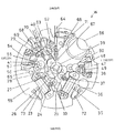
(駆動系の構成)
図2乃至図8を参照して、本例のセンサ付き多機能電子時計の機構系を説明する。図2は、本例のセンサ付き多機能電子時計の輪列、モータ、切換機構、およびスイッチング機構の構成を示す平面図である。
【0047】
図2において、本例では、4つのステップモータ23、35、54、47が内蔵されており、これらのステップモータは、いずれもコイルブロック、ステータ、およびロータで構成されている。コイルブロックは、高透磁率材からなる磁芯、それに巻かれたコイル、その両端を導通可能に処理したコイルリード基板、コイル枠から構成されている。ステータは、磁芯と同様、高透磁率材から構成されている。ロータでは、ロータ磁石に金属製のかなが取り付けられている。
【0048】
ステップモータ23、35、54、47は、いずれもCPU−IC40から出力される駆動パルスによって回転する。また、時計体の電源には、後述するコイン型のリチウム電池が用いられており、コイルには3vの直流電圧が印加されるようになっている。
【0049】
これらのステップモータのうち、A系列のステップモータ23は、通常時刻を表示するための駆動源であり、図3に示すように、ロータ24、五番車25、四番車26、三番車27、および二番車28からなる輪列を回転駆動するようになっている。これらの車のうち、二番車28は、時計体のセンター位置にある。この輪列には、日の裏車29および筒車30も機構的に接続し、そのうち、筒車30は、時計体のセンター位置にある。小秒針33は、図4に示すように、五番車25に機構的に接続され、通常時刻の秒表示を行なうようになっている。このようにして、本例では、時刻表示用指針の回転により時刻を表示する時刻表示手段が構成されている。
【0050】
図2および図5において、B系列のステップモータ35は、気圧および高度を表示するための駆動源であり、図5に示すように、ロータ36、第1の気圧表示用中間車37、第2の気圧表示用中間車38、および気圧表示車39からなる輪列を正逆方向(時計周りの方向および反時計周りの方向)のいずれの方向にも回転駆動するようになっている。これらの車のうち、気圧表示車39は、時計体のセンター位置にあり、それに気圧針11が取り付けられている。ここで、気圧針11は、時計体のセンター位置で2hPa単位で500hPaから1050hPaまでの気圧を表示するとともに、これらの気圧を標準高度に換算すれば、海面下300mから海抜5500mまでの高度も表示できるようになっている。なお、ステップモータ35およびステップモータ23には、電気的抵抗値が約3kΩの同じタイプのコイルブロックを用いてあり、約10A程度の起磁力を発生する。
【0051】
図2および図6において、C系列のステップモータ54は、アラーム設定時刻を表示するための駆動源であり、ロータ41、アラーム用中間車55、アラーム用分車56、アラーム日の裏車57、アラーム用筒車58からなる輪列を回転駆動するようになっている。これらの車のうち、アラーム用分車56、およびアラーム用筒車58は、六時を示す方向においてアラーム時針8およびアラーム分針9をそれぞれ運針するようになっている。ここで、ステップモータ54は、アラーム時刻の通常の設定時には、1分単位で運針するが、八時ボタン14を押すと、毎秒64ステップで正転方向に早送り可能である。なお、ステップモータ54は、他のステップモータ23、35に比して占有面積が小さい。また、ステップモータ54のコイルは、細い導線が用いられているので、その電気的抵抗値が約2.6kΩであり、約8Aの起磁力を有する。
【0052】
図3および図7において、D系列のステップモータ47は、10hPa未満の気圧値を1hPa単位で気圧値の表示を行なうとともに、気圧の相対的な変化を表示するための駆動源であり、1hPa単位用ロータ48、1hPa単位用中間車49、および1hPa単位用表示車50からなる輪列を回転駆動するようになっている。これらの車のうち、1hPa単位用表示車50は、十二時を示す方向において、その先端に小気圧針10が取り付けられている。
【0053】
1hPa単位用ロータ48のかな48aは、1hPa単位用中間車49の歯車49bに噛み合い、1hPa単位用中間車49のかな49aは、1hPa単位用表示車50の歯車50bに噛み合っており、1hPa単位用ロータ48のかな48aから1hPa単位用表示車50の歯車50bまでの減速比は、1/15である。また、1hPa単位用ロータ48は、1ステップで180°回転するため、1hPa単位用表示車50は、30ステップで1周360°を回転するようになっている。また、CPU−IC40は、気圧が1hPa変化すると3ステップ分の駆動パルスをステップモータ47に出力するので、1hPa単位用表示車50に取り付けられている小気圧針10は、1周10hPa分を1hPa毎に表示するようになっている。このようにして、本例では、小気圧針10および気圧針11を環境データ表示用指針として気圧値(環境データ)を表示する気圧表示手段(環境データ表示手段)が構成されている。
【0054】
なお、CPU−IC40がステップモータ47に出力する3ステップ分の駆動パルスは、その間隔が15msから30数msと非常に短いため、見た目には、小気圧針10は、1回で1目盛り分を回転したときと同様に見えるので、ユーザーにとって、違和感がない。また、1目盛り分を3分割してあるため、小気圧針10の取付け角度位置や文字板の印刷位置に誤差があっても、小気圧針10の位置と、目盛りの位置とのずれを軽減できる。
【0055】
また、本例では、1hPa単位用表示車50からは、目安表示用中間車51、目安表示用伝達車52、および目安表示車53からなる輪列に回転駆動力が伝達されるようになっている。すなわち、1hPa単位用表示車50のかな50aは、目安表示用中間車51の歯車51bに噛み合い、目安表示用中間車51のかな51aは、目安表示用伝達車52の歯車52bに噛み合っている。目安表示用伝達車52のかな52aは、目安表示車53の歯車53bに噛み合っており、この目安表示車53の回転軸の先端には、気圧(環境データ)の相対的な変化を表示するための気圧傾向針21(変化量表示用指針)が取り付けられている。
【0056】
再び、図2において、三時方向には、三時龍頭16が取り付けられる第1の巻真64が配置されている。第1の巻真64の先端側には、おしどり62およびかんぬき63が機構的に接続されている。おしどり62およびかんぬき63には規制レバー65が係合している。ここで、第1の巻真64を2段階引き出すと、規制レバー65は、四番車26の回転を規制するようになっており、四番車26の回転を規制すると、ロータ24が停止し、小秒針3の運針が停止するようになっている。この状態でも、二番歯車28aは、一定のすべりトルクをもって二番かな28bと結合しているため、小鉄車67、日の裏車29、二番車かな28b、および筒車30は回転が可能である。従って、時針1および分針2は、回転が可能である。それ故、第1の巻真64を二段階引き出すことにより、時針1および分針2の時刻合わせが可能である。
【0057】
また、第1の巻真64を一段階引き出した状態で、第1の巻真64を回転させると、その回転力は、つづみ車66および小鉄車67を介して日の裏車29に伝わり、カレンダーの修正が可能である。
【0058】
四時方向には、四時龍頭15が取り付けられる第2の巻真70が配置されている。この第2の巻真70には、アラーム用おしどり68が機構的に接続されている。ここで、四時龍頭15は、アラーム時刻を設定するとき、および時針1を単独で修正するときに用いる。すなわち、第1の巻真64を二段階引き出した状態で、四時龍頭15を操作して、第2の巻真70を回転させて時刻修正用つづみ69を回転させることにより、時針1のみを回転させることが可能である。
【0059】
なお、二時、十時、および八時方向には、それぞれスイッチレバー71、72、73がそれぞれ取り付けられている。これらのスイッチレバー71、72、73は、それぞれ二時ボタン12、十時ボタン13、および八時ボタン14に機構的に接続しており、これらのボタンを操作したときの感触を高めている。
【0060】
(小気圧針と気圧傾向針との関係)
次に、小気圧針10と気圧傾向針21との機構的な関係を説明する。
【0061】
再び、図1において、気圧傾向針21を備える気圧傾向表示部22は、三時を示す方向において、二時を示す方向から四時を示す方向に至る角度範囲に構成されている。気圧傾向表示部22では、三時方向をプラスマイナス零とし、そこから6°毎の角度間隔でプラス側およびマイナス側の双方に5目盛りが付されている。ここで、1目盛りは、約3時間前に測定した気圧と、今回測定した気圧との相対的な差が1hPaであることを表示する。たとえば、今回新たに測定した気圧が1015hPaであり、約3時間前の測定値は1013hPaであれば、3時間のうちに2hPa分だけ気圧が高くなったとして、気圧傾向針21は、12°斜め上向きの方向を指す。逆に、3時間前の測定値が1017hPaであれば、気圧傾向針21は、斜め下向きの方向を指す。以降、気圧傾向針21は、30分に一度、気圧の相対的な差を更新しながら表示する。
【0062】
ここで、気圧傾向針21は、小気圧針10と連動して回転し、しかも、小気圧針10は、測定した気圧値を表示するのに対して、気圧傾向針21は、気圧の変化を表示する。すなわち、1周360°を回転可能な小気圧針10(第1の指針)と駆動源が同じで、小気圧針10とは異なる単位系、および異なる角度範囲で回転する気圧傾向針21(第2の指針)が構成されている。それにもかかわらず、本例では、小気圧針10および気圧傾向針21のいずれをも、一つのステップモータ47で駆動できるように、以下の構成にしてある。
【0063】
まず、気圧の測定が5秒または10分毎に行なわれ、今回測定した気圧値と、3時間前に測定した気圧値との相対比較の結果を、気圧傾向針21は、30分毎に更新しながら表示する。ここで、更新時期と更新時期との間に気圧が変化して、小気圧針10が回転するとき、気圧傾向針21も回転する。しかしながら、図2および図6を参照して説明したとおり、1hPa単位用表示車50のかな50aから目安表示車53までの減速比は、1/120であるため、目安表示車53の回転角度は、極めて小さい。しかも、現実には、大気圧が1時間のうちに変化する量は、大きくても2hPaから3hPaである。従って、30分間における小気圧針10の回転角度が72°であっても、このときの目安表示車53の回転角度は、0.6°程度にすぎない。
【0064】
従って、気圧傾向針21は、表示の更新時期の間に気圧の変動があってもプラスマイナス1/4目盛りの範囲を回転するだけである。しかも、気圧傾向針21の機能は、気圧の相対変化をその傾斜角によって示すだけでよいものであり、厳密性を強く求められるものではない。それ故、1つのステップモータで駆動することに起因して、更新時期と更新時期との間において、気圧傾向針21が小気圧針10とともに回転しても、実使用上の問題点がない。逆に、同じ駆動モータで駆動される2つの指針があるので、部品点数を大幅に増やすことなく、表示可能な情報量を増やすことができる。
【0065】
なお、小気圧針10から気圧傾向針21までの間には、2つの中間車が設けられているので、回転方向が逆である。また、小気圧針10が1周360°を回転すると、気圧傾向針21は、逆方向に3°回転する。逆に、気圧の相対的な変化がプラス2hPaであるとき、小気圧針10は、4周を逆方向に回転して元の気圧表示の目盛り位置を指す。
【0066】
また、小気圧針10と気圧傾向針21との取付け位置は、小気圧針10が0位置(12時方向)にあるとき、気圧傾向針21は、0位置(三時を示す方向)に対して1.5°の角度分(1/4目盛り)だけ斜め下方に向けて取り付けられている。従って、小気圧針10が正回転方向(時計周りの方向)に気圧傾向針21の5目盛り分回転したときでも、気圧傾向針21は、目盛り上を逆回転方向(反時計周りの方向)に回転する。気圧が低下したことを表示できる範囲を広く確保した方が、天候の悪化を監視しやすいという点で便利であるからである。また、小気圧針10は、9hPaの位置にくるまで正回転方向に回転した後、そこから1hPa上昇するときには、逆方向(反時計周りの方向)に回転して0hPaを指す。このとき、気圧傾向針21は、再び0位置(三時を示す方向)に対して1.5°の角度分(1/4目盛り)だけ斜め下方を指す。同様に、気圧が降下し、小気圧針10が逆転して1周する場合には、気圧傾向針21は、正回転方向に回転して0hPaに戻る。
【0067】
(小気圧針および気圧傾向針の0°位置合わせ)
次に、電池を交換したときなどに行なう小気圧針10と気圧傾向針21の0°位置合わせの方法を説明する。
【0068】
まず、三時龍頭16を二段階引き出した後に、二時ボタン12および十時ボタン13を同時に押すことによりシステムリセットして、CMOS−ICに内蔵されたCPUを初期化した後に、二時ボタン12を押すと、小気圧針10は、逆方向(反時計周りの方向)に回転する。ここで、図8に示すように、目安表示車53には、左右対称に15枚の歯形が2組形成され、歯形のない部分がある。従って、この歯形のない部分によって、気圧傾向針21の回転は、所定の角度位置で強制的に停止するようになっている。それ故、CPU−IC40からの逆転駆動パルスの出力が終了した後に、小気圧針10を0°位置に合わせるのに、気圧傾向針21の停止位置を基準にすることができる。
【0069】
また、指針の動く範囲が規定されているため、六時を示す方向にある副針(アラーム設定時刻表示用の指針)などと干渉することがない。従って、他の副針を同じ高さ位置に設定でき、針の高さ位置を低く抑えることができる。それ故、本例では、センター位置に4本の針が取り付けられているが、気圧傾向針21とアラーム時針8とを文字板5から同じ高さ位置に設定することにより、時針1および分針2の高さ位置を従来の3針タイプの多軸時計と同じ高さ位置に設定することができる。
【0070】
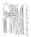
(センサの配置構造)
図9において、時計の各構成部品は、基枠である地板55に支持された状態にある。地板55には、外周寄りの位置には、センサ取付け用のセンサ収納部55aが凹部として形成されており、そこに圧力センサ56が収納されている。ここで、センサ収納部55aは、図2に示すように、いずれの輪列、およびステップモータ24、35、54、47とも平面的にずらした位置に形成されている。
【0071】
再び、図9において、センサ収納部55aでは、圧力センサ56と地板55との間に第1のパッキン57が配置されている。第1のパッキン57は、センサ押さえ板58がねじ止めされることにより、圧力センサ56とセンサ収納部55aとの間に挟まれた状態にあり、そこでの防水性を確保している。地板55には、センサ収納部55aから地板55の表面に抜ける第1の貫通孔55bが形成されている。ここで、第1の貫通孔55bは、センサ収納部55aの中心から外周寄りにずれた位置に形成されている。第1の貫通孔55bは、外装ケース32に斜めに形成された第2の貫通孔32aに連通している。外装ケース32の外面側では、第2の貫通孔32aが回転ベゼル19の下方位置で開口しており、回転ベゼル19と外装ケース32との間には、隙間19aが確保されている。従って、圧力センサ56のセンシング面は、貫通孔55b、32aからなる必要最小限の通路を介して外気に連通している。このような構成によれば、回転ベゼル19が第2の貫通孔32aの外面側開口を覆っているので、保護板などを用いなくても第2の貫通孔32aおよび第1の貫通孔55bにほこりやごみなどが侵入することを防止できる。また、回転ベゼル19に代えて、その他の時計体の固定枠で覆ってもよい。
【0072】
本例では、第1の貫通孔55bは、地板55の筒部55cを貫通するように形成され、この筒部55cは、周囲に第2のパッキン59が装着された状態で第2の貫通孔32aの拡張部分32b(凹部)に嵌め込まれている。この第2のパッキン59は、地板55と外装ケース19との間の防水性を確保している。
【0073】
このように、本例では、圧力センサ19が地板55の外周寄りの位置に配置されているため、日車6やステップモータ23、35、47、54などと重ならない位置に配置できる。また、第1の貫通孔55bは、センサ収納部55aの外周寄りの位置に形成されているので、第2の貫通孔32aも、日車6などの部品から離れた位置に形成できる。また、センサ収納部55aをいずれの輪列、およびステップモータ24、35、54、47からも平面的にずらした位置に形成してあるので、地板55や外装ケース19は、薄いままでよい。しかも、地板55や外装ケース19の外周側に突出部分を形成しなくても、貫通孔55b、32aやセンサ収納部55aの形成位置を確保することができる。それ故、薄い時計体を構成できるとともに、回転ベゼル19(円形ムーブメント)からセンサ収納部55aが張り出さないデザイン的にも優れたセンサ付き多機能電子時計Wを実現することができる。
【0074】
(別の形態におけるセンサの配置構造)
なお、図10に示すように、地板55、センサ押さえ板58、およびセンサ枠61によってセンサ収納部55dを構成し、そのうち、地板55の内面に位置する回路スペーサ60とセンサ押さえ板58とによって、圧力センサ56を挟むようにしてもよい。この場合にも、第1の貫通孔55aをセンサ収納部55dの外周寄りの位置に形成することによって、日車6やステップモータ23、35、47、54などと重ならない位置に第1の貫通孔55aを形成できる。それ故、センサ付き多機能電子時計の薄型化に有利である。
【0075】
(電子部品の配置構造)
さらに、図11にも示すように、圧力センサ56は、センサ押さえ板58をねじ77、78で止めてある。このため、第1のパッキン57および第2のパッキン59は、確実に押さえられているので、防水性が高い。
【0076】
なお、図11において、圧力センサ56は、回路カバー81により完全に保護されている。この回路カバー81は、圧力センサ56のアナログ信号をデジタル信号に変換するA/D変換IC76(アナログデジタル変換IC)も覆っている。電池74は、ねじ79、80で着脱自在な電池押さえ75により押さえつけられた状態で装着されている。ここで、圧力センサ56、A/D変換IC76、および電池74も、互いに重ならない位置にあるので、センサ付き多機能電子時計の薄型化に有利である。
【0077】
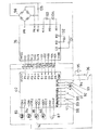
(制御系の構成)
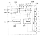
図12は、本例のセンサ付き多機能電子時計の回路結線図である。
【0078】
この図において、本例のセンサ付き多機能電子時計Wの電子回路系は、その時刻表示系および気圧表示系を制御するCPU−IC40、ダイヤフラム上に形成されたピエゾ抵抗のピエゾ抵抗効果を利用して500hPaから1050hPaまでの圧力を測定可能な圧力センサ56(半導体センサ)、および圧力センサ56の測定結果をデジタル信号化するA/D変換IC76から大略構成されている。
【0079】
CPU−IC40は、ワンチップ上にコアCPU、プログラムメモリ、モータドライバ、モータ運針制御回路などを集積したアナログ電子時計用のマイクロコンピュータである。CPU−IC40に対しては、内蔵の発振回路の源振となるべき音叉型水晶振動子87、および内蔵の定電圧回路の電圧変動を抑えるための容量が0.1μFのキャパシタ88が回路接続している。CPU−IC40には、かんぬき63の一部に形成されたスイッチ89、およびアラーム用おしどり68の一部に形成されたスイッチ90を介して、三時龍頭16および四時龍頭15に対して行なわれた操作内容が入力されるようになっている。そのうち、スイッチ89は、第1の巻真64の動きに連動して、三時龍頭16を一段階引き出したときに端子RA1と閉じ、二段階引き出したときに端子RA2と閉じるようになっている。スイッチ90は、第2の巻真70の動きに連動して、四時龍頭15を一段階引き出したときに端子RB1と閉じ、二段階引き出したときに端子RB2と閉じるようになっている。また、CPU−IC40には、二時ボタン12、十時ボタン13、および八時ボタン14の操作に連動するスイッチ91、92、93が構成されており、これらのスイッチは、二時ボタン12、十時ボタン13、および八時ボタン14をプッシュ時にその旨の信号を入力するようになっている。また、CPU−IC40からは保護ダイオード付きのトランジスタ96に制御信号が出力されており、昇圧コイル94、および腕時計ケースの裏蓋側に取り付けられた圧電ブザー95によって、確認用のブザー音(報知音)を必要に応じて発するようになっている。さらに、CPU−IC40は、各ステップモータ24、35、54、47のコイルブロック83、84、85、86に駆動パルスを出力するようになっている。
【0080】
A/D変換IC76には、積分回路、二重積分を行なうためのタイミング制御回路、アナログ信号を増幅するためのプリアンプ、圧力センサ56を駆動するための定電圧発生回路などが内蔵されている。また、A/D変換IC76には、積分回路の一部を構成する積分コンデンサ131、および積分抵抗132が回路接続されている。さらに、A/D変換IC76には、デジタル変換すべきアナログ信号を増幅するためのプリアンプの一部を構成する抵抗133、134と、内蔵の定電圧回路の電圧を安定化するための容量が0.1μFのキャパシタ135とが回路接続されている。
【0081】
CPU−IC40とA/D変換IC76とは、信号線151〜155、および信号線156〜159で電気的に接続されている。CPU−IC40からA/D変換IC76へは、信号線151〜155を介し、A/D変換IC76を制御するための基準クロック信号、およびA/D変換開始信号などが出力されるようになっている。A/D変換IC76からCPU−IC40へは、信号線156〜159を介して、A/D変換結果が出力されるとともに、信号線160を介して、A/D変換が終了した旨の信号も出力されるようになっている。
【0082】
(CPU−ICの構成)
図13は、CPU−IC40の機能を示すブロック図である。
【0083】
この図において、CPU−IC40のコアCPU201には、ALU(演算装置)、演算用レジスタ、スタックポインタ、インストラクションレジスタ、およびインストラクションデコーダなどが構成されており、周辺回路とは、メモリマップI/O方式によりアドレスバス、およびデータバスで接続されている。プログラムメモリ202は、マスクROMで構成され、ICを動作させるためのソフトウエアを格納してある。このプログラムメモリ202のアドレスは、アドレスデコーダ203によって指定する。
【0084】
データメモリ204は、RAMで構成され、そのアドレスは、アドレスデコーダ205によって指定する。データメモリ204は、図14に示すように、秒カウンタ601、および時分カウンタ602に加えて、気圧値603、気圧針針位置604、小気圧針針位置605、気圧針の現在の針位置606、小気圧針の現在の針位置607、気圧針針位置と現在の針位置との差608、小気圧針針位置と現在の針位置との差609、アラームセット時刻610、3時間前の気圧611、3時間前との気圧差612を記録するカウンタが構成されている。なお、本例では、気圧差612(環境データの変化量)を演算する変化量検出手段としての機能をコアCPU201が担っている。
【0085】
再び、図13において、発振回路20は、端子XIN、XOUT に接続された音叉型水晶発振子87を源振として32768Hzで発振する。発振回路20から出力された32768Hzの信号は、分周回路207で1Hzの信号に分周される。サウンドジェネレータ208は、コアCPU201からの命令に基づいてブザー駆動信号を形成し、端子ALに出力する。インタラプト制御回路215は、分周回路207、モータ運針制御回路209、入出力制御回路211と接続され、タイマ割り込み、モータ制御割り込み、およびキー割り込みをコアCPU201に出力する。
【0086】
モータ運針制御回路209は、コアCPU201からの命令により正回転駆動パルス、逆回転駆動パルス、および補正駆動パルスを発生し、A系列からD系列のモータドライバ210〜213に出力する。これらのモータドライバ210〜213は、モータ運針制御回路209で生成された正回転駆動パルス、逆回転駆動パルス、および補正駆動パルスをA系列からD系列の対応するステップモータ23、35、54、47にそれぞれ出力する。
【0087】
入出力制御回路214は、二時ボタン12、十時ボタン13、および八時ボタン14のスイッチ91〜94に対応する端子A〜C、三時龍頭16のスイッチ89に対応する端子RA1、RA2、四時龍頭15のスイッチ90に対応する端子端子RB1、RB2、入力端子D1〜D5、および出力端子P1〜P5を制御する。また、入出力制御回路214は、発振回路206と接続され、コアCPU201からの命令に基づいて、出力端子P1に32768Hzのクロック信号を出力する。
【0088】
(A/D変換ICの構成)
図15は、A/D変換IC76の機能を示すブロック図である。
【0089】
図において、定電圧発生回路306は、圧力センサ56を駆動するための電圧Vs、およびA/D変換に必要な各レベルの基準電圧を発生している。圧力センサ56が駆動されると、圧力に応じた電圧が発生し、それが入力端子IN1、IN2より入力される。入力端子IN1、IN2より入力された差動入力電圧は、差動−シングルエンド変換回路301において基準電圧に対する電位差に変換される。この電位差を示すアナログ信号は、プリアンプ302で数倍、または数十倍に増幅される。その増幅率は、端子VC1、RO、R1に接続される抵抗133、134の抵抗値の比によって規定されるので、入力端子IN1、IN2から入力されたアナログ信号をどのレベルの分解能をもつデジタル信号にするかによって、抵抗133、134の抵抗値を設定する。A/Dコンバータ303は、端子R3、R2、C0に積分抵抗132および積分キャパシタ131を接続して使用される。実際の動作において、A/Dコンバータ303の状態は、時系列的には正積分時間と逆積分時間とに分かれ、そのうち正積分時間は、タイミング制御回路305により制御される。A/D変換結果は、12ビットで格納されており、CPU−IC40から入力端子I2、I3を介して入力される制御信号に基づいて、4ビットずつに区切られた3つの4ビットデータのうちのいずれかが出力端子O1、O2・・から出力されるようになっている。このようなマルチプレクサなどにより、インターフェース回路304が構成されている。
【0090】
(運針動作)
このように構成した駆動系、および制御系によって行なわれる時刻および気圧値の表示動作を、図16を参照して説明する。
【0091】
図16は、本例のセンサ付き多機能電子時計の表示動作を示すフローチャートである。なお、以下に説明する動作は、三時龍頭16および四時龍頭15のいずれをも通常状態にまで押し込んだ状態で行なわれる。
【0092】
まず、1Hzのタイマ割り込みがあると、ステップST101で端子RA2がOFFであるか否か、すなわち、三時龍頭16が2段階引き出された状態にあるか否かを判断する。ここで、三時龍頭16が2段階引き出されていないと判断した場合には、ステップST102で、コアCPU201は、モータ運針制御回路209に正回転駆動パルス出力命令を出力し、A系列のモータドライバ210は、A系列のステップモータ23に対して正回転駆動パルスを出力する。その結果、ステップモータ23が正方向に180°回転し、小秒針3を右周り(正回転の方向)に6°回転させて、秒表示を行なう。また、分針2、時針1、24時針4も輪列を介して小秒針3と連動して運針する。
【0093】
一方、気圧の測定、およびその表示は、以下のとおり行なわれる。
【0094】
1Hzのタイマ割り込みがあった以降、ステップST103では、秒カウンタ601に「1」を加算する。ステップST104で分の桁上げがあるか否かを判断し、分の桁上げがあれば、ステップST105で時分カウンタ602に「1」を加算する。
【0095】
ステップST106で正10分になったか否かを判断し、正10分であると判断した場合には、以降、気圧の測定、およびその表示を実行する。
【0096】
この気圧の測定の処理では、まず、ステップST107で端子P1より32768Hzのクロック信号を出力した後、ステップST108〜ステップST109で、出力端子P2〜P5を順次、「H」レベルとする。この切換に基づいて、A/D変換IC76で圧力センサ56の検出結果(アナログ信号)をデジタル変換し、このA/D変換が終了すると、A/D変換IC76の出力端子O5を「H」レベルにする。この出力端子O5は、CPU−IC40の入力端子D5に接続しているので、入力端子D5が「H」レベルになるまで、ステップST110で待機する。
【0097】
入力端子D5が「H」レベルになると、ステップST111で、CPU−IC40は、出力端子P4、5よりデータを選択しながら、入力端子D1〜D4より気圧測定値のA/D変換結果を取り込む。ステップST112では、コアCPU201がA/D変換結果に定数を加算および乗算して気圧値603を計算する。ステップST113では、コアCPU201が気圧針11の針位置604を計算し、現在の針位置606との差608を計算する。併せて、コアCPU201が小気圧針10の針位置605を計算し、現在の針位置607との差609を計算する。ステップST114で、針位置の差608、609が正の場合には、正回転駆動パルスを、負の場合には、逆回転駆動パルスを差608、609に相当するパルス数だけB系列およびD系列のモータドライバ211、213から出力する。その結果、気圧針11および小気圧針10は、所定の位置まで回転し、測定した気圧値を表示する。
【0098】
ステップST115で、このときのタイミングが正30分である場合には、ステップST116で、3時間前の気圧測定値611と今回測定した測定値603との差612を計算し、ステップST117で必要な数だけのパルスをD系列のステップモータを駆動する。その結果、気圧傾向針21は、所定の位置まで回転し、気圧差613を表示する。
【0099】
なお、ステップST104において、分の桁上がりがあると判断した以降、ステップST106で正10分でない場合、またはステップST115で正30分でないと判断した後には、ステップST118において、データメモリ104に記憶されているアラームのセット時刻610と現在の時刻602とを比較する。アラームのセット時刻610と現在の時刻602とが一致していた場合には、コアCPU201からの命令によりサウンドジェネレータ208がアラーム発生指令信号を出力してトランジスタ96を駆動し、アラームを鳴鐘する。以降、次の割り込みがあるまで、他の処理に移行する。
【0100】
〔実施例2〕
次に、本発明の実施例2を説明する。なお、本例のセンサ付き多機能電子時計は、基本的な構成が実施例1に係るセンサ付き多機能電子時計と同様であるため、共通する機能を有する部分には同じ符号を付してそれらの説明を省略する。
【0101】
本例では、図17に示すように、CPU−IC40のデータメモリ204は、秒カウンタ601、時分カウンタ602、気圧値603、気圧針針位置604、小気圧針針位置605、気圧針の現在の針位置606、小気圧針の現在の針位置607、気圧針針位置と現在の針位置との差608、小気圧針針位置と現在の針位置との差609、アラームセット時刻610、3時間前の気圧611、3時間前との気圧差612に加えて、最低気圧613、気圧補正モード614、および電池寿命615をも記憶するようになっている。
【0102】
以下に、本例のセンサ付き多機能電子時計で行なわれる動作を、図18を参照して説明する。図18は、本例のセンサ付き多機能電子時計の表示動作を示すフローチャートである。
【0103】
1Hzのタイマ割り込みが発生すると、ステップST201で端子RA2がOFFであるか否か、すなわち、三時龍頭16が2段階引き出されているか否かを判断する。三時龍頭16が2段階引き出されていない場合には、現在時刻をカウントするために、ステップST202でデータメモリ204の秒カウンタ601に「1」を加算する。次に、ステップST203でデータメモリ204に電池寿命表示実行中であることを示すフラグが「1」か「0」であるかを判断する。ここで、フラグが「1」であるとは、電池の寿命が尽きつつあるため、2秒ごとに2ステップの運針を行なって、使用者に電池寿命が尽きつつあることを知らせる。これに対し、フラグが「0」である場合には、通常の運針を行なう。
【0104】
通常運針では、ステップST204で分の桁上げがあるか否かを判断し、桁上げがある場合には、ステップST205で時分カウンタ602に「1」を加算した後、ステップST206で正10分であるか否かを判断する。ここで、正10分であると判断した場合には、ステップST207でステップモータに正回転パルスを1発出力し、以下の気圧測定および気圧表示の処理を行なう。このときの正回転パルスは、以降に行なうA/D変換の処理を行う時間を確保できるように、大きなトルクで指針を駆動し、運針を短時間のうちに実行するようになっている。
【0105】
気圧測定の処理では、まず、ステップST208で出力端子P1より32768Hzのクロック信号を出力した後、ステップST209〜ステップST210で、出力端子P2〜P5を順次、「H」レベルとする。A/D変換IC76でのA/D変換が終了すると、A/D変換IC76の出力端子O5が「H」レベルになるので、CPU−IC40は、入力端子D5が「H」レベルになるまで、ステップST211で待機する。
【0106】
入力端子D5が「H」レベルになると、ステップST212で、CPU−IC40は、出力端子P4、5よりデータを選択しながら、入力端子D1〜D4より気圧測定値のA/D変換結果を取り込む。ステップST213では、コアCPU201がA/D変換結果に定数を加算および乗算して気圧値603を計算する。ステップST214では、気圧針11および小気圧針10の針位置604、605を計算し、現在の針位置606、607との差608、609を計算する。ステップST215で、針位置の差608、609が正の場合には、正回転駆動パルスを、負の場合には、逆回転駆動パルスを差608、609に相当するパルス数だけB系列およびD系列のモータドライバ211、212から出力する。その結果、気圧針11および小気圧針10は、所定の位置まで回転し、測定した気圧値を表示する。
【0107】
次に、ステップST217で、今回の測定値がデータメモリ204に記憶された過去の最低気圧613より小さい場合には、最低気圧613の内容を今回の測定値に変更する。
【0108】
ステップST218では、このときのタイミングが正30分であるか否かを判断し、正30分である場合には、ステップST219で、3時間前の気圧測定値611と今回測定した測定値603との差612を計算する。ステップST220では、必要な数だけのパルスを出力し、D系列のステップモータ47を駆動する。その結果、気圧傾向針21は、所定の位置で気圧差を表示する。
【0109】
なお、ステップST216で今回の測定値がデータメモリ204に記憶された過去の最低気圧613より大きい場合には、最低気圧613の内容を更新せずに、ステップST218でこのタイミングが正30分であるか否かを判断する。
【0110】
次に、ステップST221で電池電圧が低下しているか否かを判断し、低下してない場合には、ステップST222でアラームセット時刻と現在時刻とを比較する。現在時刻がアラームセット時刻と一致していた場合には、ステップST223でアラームを発生させた後に、他の処理に移行する。これに対し、ステップST221で電池寿命が尽きつつあると判断した場合にはフラグ「1」をセットした後、アラーム処理を行なわずに他の処理に移行する。
【0111】
本例では、ステップST204で分の桁上がりがないと判断した場合には、ステップST225でA系列のステップモータに補正運針パルスを1発出力し、しかる後に、処理に移行する。同様に、ステップST206で正10分でないと判断した場合にも、ステップST226でA系列のステップモータに補正運針パルスを1発出力し、しかる後に、他の処理に移行する。これらの場合には、気圧測定の処理を行なわない。ここで行なう運針方法は、気圧の測定を行なうときの運針に比して、小さなトルクで運針を行い、その消費電力を節約している。すなわち、圧力センサ56のデータ測定期間と、その休止期間との間で時刻表示用指針の運針方法を切り換える運針方法切換手段が構成されている。従って、センサ付きのアナログ電子時計、またはアナログデジタル両表示の電子時計において、補正駆動方式を採用しても、圧力センサ56の測定期間における運針を短時間に済ませることによって、センサの測定結果のデジタル化に要する時間を充分に確保できる。
【0112】
また、ステップST203で電池の寿命が尽きつつあると判断した場合には、使用者に電池寿命が尽きつつあることを認識させるための運針を行なう。すなわち、ステップST227で偶数秒でないと判断した場合には、他の処理に移行し、運針しない。これに対し、ステップST227で偶数秒であると判断した場合には、ステップST228で正回転パルスを2発(2秒分)出力した後に、他の処理に移行する。従って、2秒毎に2ステップの運針を行なうため、使用者に電池寿命が尽きつつあることを知らせることができる。なお、この場合には、気圧の測定を行なわない。
【0113】
このようにして、本例では、付加機能駆動手段として構成したアラーム手段の動作タイミングに合わせて、電源電圧を監視する電源電圧検出手段と、その監視結果に基づいて運針方法を変える駆動制御手段が構成されている。従って、電源電圧を監視するタイミングのみを制御する特別の計数手段を設けなくても、電源電圧の監視、およびそれに対応した制御を行なうことができる。
【0114】
本例では、B系統のステップモータ35へのパルス出力において、図19に示すフローチャートに従って気圧針11を回転させるバックラッシュ防止手段が構成されているので、バックラッシュに起因する表示のずれが発生しない。
【0115】
ここで、気圧表示第1中間車37、気圧表示第2中間車38、気圧表示車39によるバックラッシュは、駆動パルス1ステップ分に相等する大きさとする。
【0116】
図19において、ステップST301でB系列のステップモータ35およびD系列のステップモータ47に駆動パルスを出力した後、ステップST302でB系列のステップモータ35による今回の表示位置と、現在の表示位置とを比較する。ここで、今回の表示位置が現在の表示位置より大きいと判断した場合には、ステップST303でステップモータ35による前回の運針方向が正回転方向か否かを判断する。
【0117】
ステップST303で、前回の運針方向が正回転方向であると判断した場合には、ステップST304でステップモータ35を駆動して今回の表示を行なう。すなわち、今回の表示位置から前回の表示位置との差に相当する数だけの正回転方向の駆動パルスをステップモータ35に出力する。
【0118】
これに対し、ステップST303で、前回の運針方向が逆回転方向であると判断した場合には、ステップST305では、今回の表示位置から前回の表示位置との差に相当する数に対して1発余分の正回転方向の駆動パルスをステップモータ35に出力する。従って、第1の気圧表示用中間車37、第2の気圧表示用中間車38、および気圧表示車39のバックラッシュが補正され、気圧針11は、指示ずれのない状態で気圧値を表示する。
【0119】
これに対して、ステップST302で今回の表示位置が現在の表示位置より大きいと判断した場合には、ステップST310でB系列のステップモータ35による今回の表示位置と、現在の表示位置とを比較する。ここで、今回の表示位置が現在の表示位置より小さいと判断した場合には、ステップST311でステップモータ35による前回の運針方向が逆回転方向か否かを判断する。ステップST311で、前回の運針方向が逆回転方向であると判断した場合には、ステップST312今回の表示位置から前回の表示位置との差に相当する数だけの正回転方向の駆動パルスをステップモータ35に出力する。ステップST311で、前回の運針方向が正回転方向であると判断した場合には、ステップST313では、今回の表示位置から前回の表示位置との差に相当する数に対して1発余分の逆回転方向の駆動パルスをステップモータ35に出力する。従って、この場合も、バックラッシュが補正され、気圧針11は、指示ずれのない状態で気圧値を表示する。
【0120】
次に、ステップST306でD系列のステップモータ47による今回の表示位置が現在の表示位置より大きいか否かを判断する。ここで、今回の表示位置が現在の表示位置より大きいと判断した場合には、ステップST307で今回の表示位置から前回の表示位置との差に相当する数の正回転方向の駆動パルスをステップモータ47に出力する。これに対し、ステップST306で今回の表示位置が現在の表示位置より大きくないと判断した場合には、ステップST308で今回の表示位置が現在の表示位置より小さいか否かを判断する。ステップST306で今回の表示位置が現在の表示位置より小さいと判断した場合には、ステップST309で今回の表示位置から前回の表示位置との差に相当する数の逆回転方向の駆動パルスをステップモータ47に出力する。
【0121】
なお、ステップST310で今回の表示位置が現在の表示位置より小さくないと判断した場合には、同じ表示位置であるとして、ステップモータ47の駆動を行なわない。
【0122】
(小気圧針と気圧傾向針の0位置合わせの処理)
次に、小気圧針10と、気圧傾向針21の0位置合わせの処理を、図20を参照して、説明する。この処理は、小気圧針10と、気圧傾向針21の0位置がずれた場合に、三時龍頭16を二段階引き出した状態で二時ボタン12および十時ボタン13を同時に押すことにより行なう。
【0123】
図20において、まず、ステップST401で端子R2AがONであるか否かに基づいて、三時龍頭16が二段階引き出されているか否かを判断し、ONであると判断した場合には、ステップST402で端子AがOFFからONに切り換わったか否かを判断する。ここで、二時ボタン12が押されて端子AがOFFからONに切り換わったと判断した場合には、ステップST403で0位置合わせのモードに入ったか否かを判断する。
【0124】
ステップST403で0位置合わせのモードに入っていないと判断した場合には、D系列のステップモータ47に対し、800発の逆回転パルスを出力する。ここで、気圧傾向針21の目安表示車53には、図8を参照して先に説明したように、左右対称に15枚の歯形が2組形成され、歯形のない部分がある。従って、小気圧針10と、気圧傾向針21とは、歯形が形成されている部分の端部に規定された位置で停止する。パルスの出力が終了すると、ステップST405で0位置合わせのモードに入る。
【0125】
従って、再度、割り込みがあった以降、ステップST403で0位置合わせモードに入っていると判断した場合には、ステップST406でステップモータ47に正回転パルスを1発出力して、気圧傾向針21の0位置を調整する。
【0126】
なお、図20に示すフローチャートに代えて、図21に示すフローチャートに基づいて0位置合わせを行なうことにより、0位置合わせを短時間で行なうことができる。
【0127】
図21において、ステップST501で端子R2AがONであるか否かを判断し、ONであると判断した場合に、ステップST502で二時ボタン12が押された否かを判断する。ここで、二時ボタン12が押されたと判断した場合には、ステップST503で0位置合わせのモード中であるか否かを判断する。
【0128】
ここで、0位置合わせのモードに入っていないと判断した場合には、ステップST504でD系列のステップモータ47に対して800発の逆回転パルスを出力して、気圧傾向針21を逆方向(反時計周りの方向)に回転させる。このとき、気圧傾向針21には、その一部にのみ歯形が形成されているため、小気圧針10と、気圧傾向針21とは、歯形が形成されている部分の端部で停止する。その後に、ステップST505でステップモータ47に対して360発の正回転パルスを出力して、気圧傾向針21を時計周りに回転させる。その結果、気圧傾向針21は、0位置の手前で停止した状態にあり、ステップST506でパルスの出力が終了すると、0位置合わせモードになる。
【0129】
以降、割り込みあって、ステップST503で0位置合わせモードに入っていると判断した場合には、ステップST507でステップモータ47に正回転パルスを1発出力する。その結果、気圧傾向針21は、すでに0位置の手前で停止した状態にあるので、正回転パルスで0位置に合う。
【0130】
このようにして、本例では、歯形の非形成部分を利用して、指針の回転を停止させた後に、この停止位置を基準に指針の位置を調整する指針位置調整手段が構成されているので、簡単、かつ正確に指針位置の調整を行なうことができる。
【0131】
(気圧最低値の呼出動作)
次に、測定した気圧値の最低値を表示するための動作を、図22を参照して説明する。
【0132】
図22において、ステップST601では、端子RA1、RA2がOFF、すなわち、三時龍頭16が通常位置にあるか否かを判断する。ここで、三時龍頭16が通常位置にあると判断した場合には、ステップST602で十時ボタン13(Bスイッチ)が押されたか否かを判断する。ステップST602で十時ボタン13が押されたと判断すると、ステップST603で気圧を一回測定し、その測定値を過去10分毎の最低値であるデータメモリ204の最低気圧613と比較する。
【0133】
ここで、今回の測定値が最低気圧値である場合には、今回の測定値をデータメモリ204の最低気圧613に書き込んだ後に、ステップST606で最低気圧613を表示する。このようにして、最低気圧613(特定データ)を表示直前に更新する特定データ更新手段が構成されているので、最新のデータに基づいて情報を表示できる。
【0134】
これに対して、今回の測定値が、これまでの最低気圧値より大きかった場合には、そのままステップST606で最低気圧613を表示する。
【0135】
(気圧針を校正するための動作)
気圧の測定値を校正するための動作を、図23を参照して説明する。この動作は、たとえば、気圧値がずれた場合に、気圧基準器などを合わせるときに行なう。具体的には、三時龍頭16を一段階引き出した状態で二時ボタン12および十時ボタン13の双方を同時に押すことによって行なう。
【0136】
図23において、ステップST701で端子RA1がONであるか否か、すなわち、三時龍頭16が一段階引き出されているか否かを判断する。ここで、端子RA1がONであると判断した場合には、ステップST702で気圧値補正モードになっているか否かを判断する。このときの判断は、データメモリ204のフラグが「0」であるか否かに基づいて行ない、データメモリ204のフラグが「0」である場合には、気圧値補正モードに入っていないと判断する。
【0137】
気圧値補正モードに入っていないと判断し、かつ、ステップST703で二時ボタン12(Aスイッチ)および十時ボタン13(Bスイッチ)の双方が同時に押されたと判断すると、ステップST704で気圧値を測定する。次に、ステップST705で二時ボタン12(Aスイッチ)および十時ボタン13(Bスイッチ)が2秒以上押されたと判断した場合には、まず、ステップST706で測定値を表示する。しかる後に、ステップST707で気圧値の補正を行なうとして、データメモリ204のフラグに「1」を書き込んだ後に、ステップST708でその旨を知らせる報知音を鳴らす。
【0138】
以降、割り込みがあって、ステップST702で気圧補正モードになっていると判断し、かつ、ステップST709で二時ボタン12(Aスイッチ)が押されたと判断した場合には、ステップST710で気圧の測定値に1hPaを加算する補正を行なう。しかる後に、ステップST711で補正された気圧値を表示する。
【0139】
これに対し、ステップST712で十時ボタン13(Bスイッチ)が押されたと判断した場合には、ステップST713で気圧の測定値に1hPaを減算する補正を行なう。しかる後に、ステップST711で補正された気圧値を表示する。
【0140】
このように、本例では、校正可能なモードに入る操作中に気圧値を測定した後にそのまま表示させる校正手段を構成したので、正確な校正を行なうことができる。しかも、気圧計測を実行した後に、電力を必要とする報知音を鳴らす報知音発生手段を構成したので、電圧変動による気圧計測誤差が小さい。それ故、信頼性の高い校正を行なうことができる。
【0141】
(気圧傾向針が行なう気圧変化の表示に対する補正の動作)
次に、気圧傾向針が気圧変化を表示するときに、移動などに起因する急激な気圧変化を除外するための補正処理の一例を、図24を参照して説明する。
【0142】
本例の補正方法では、まず、所定の時間内に一定以上の気圧変化があった場合には、そのデータを用いず、それを他のデータで補完する。さらに、変化が大きなデータが多数あった場合には、補完処理を行なわない。
【0143】
たとえば、3時間(単位期間)の気圧差を比較するにあたって、基本的には、3時間前から現在まで、30分毎に気圧の測定値の差を求め、これらの6つの気圧差のデータの和を気圧差として3時間毎に表示する。ここで、30分毎の気圧差のデータのうち2hPa以上のデータを棄てて、残るデータの和に基づいて気圧の変化量を求める。すなわち、所定の単位期間内にセンサが測定した一定時間毎の環境データの変化量を示すデータ群のうち、所定の値より大きな値のデータを異常データと判断する異常データ検出手段と、データ群から異常データを除いたデータに基づいて、単位期間が経過する前後の環境データの変化量に補完した内容を表示内容として演算するデータ補正手段とを設けてある。
【0144】
また、30分毎の気圧差のデータのうち、2hPa以上のデータの数が5個以上の場合には、補完処理を行なわずに、6つの気圧差のデータの和をそのまま気圧の差とする。
【0145】
このような処理を行なう目的に、図24において、まず、ステップST801〜ステップST804で、ある時刻での気圧の測定値と、この時刻から30分前の気圧の測定値との差Dnを順次求める。
【0146】
次に、ステップST805〜ステップST807で変数を初期化する。ステップST808〜ステップST812では、30分毎の各気圧の差Dnの絶対値が2hPa以上であるか否かを判断しながら、2hPa以上の変化量をもつデータを棄てるとともに、棄てたデータの数mと、残ったデータの和Sとを求める。
【0147】
次に、ステップST813で棄てたデータの数mが5以上であるか否かを判断する。ここで、棄てたデータの数mが5未満であると判断した場合には、和Sに対し、6/(6−m)を乗じた値を求め、この値を気圧差として表示する。これに対して、棄てたデータの数mが5以上である場合には、6つの気圧差のデータの和Sをそのまま気圧の差とする。
【0148】
このような補正方法を用いれば、海抜差の大きな地点を通過したことに起因する気圧の大きな変化があっても、このデータは、棄てられる。
【0149】
なお、図24に示す方法において、ステップST814では、和Sに対して、(6/6−m)を乗じているが、たとえば、mが1の場合には、有効なデータの和Sをそのまま使用し、mが2の場合には、有効なデータの和Sに1.5を乗じ、mが3または4の場合には、有効なデータの和Sに2を乗じてもよい。このようにして、処理を簡素化すれば、バイナリーでの演算が簡単になるので、表示の高速化および省電力化に有利である。
【0150】
また、気圧の差を求める際に行なう補正方法としては、図25に示す方法を用いてもよい。
【0151】
この方法では、気圧差を算出するのに単純に2点間の気圧差を求めるのではなく、時間的に離れたデータ同士の比較も行なう。
【0152】
たとえば、3時間(単位期間)における気圧差を求める場合には、単位時間を1時間ずつ3分割し、まず、1時と2時の気圧変化を計算する。この計算にあたって、基本的には、0時40分の気圧測定値(データa1)、0時50分の気圧測定値(データa2)、および1時00分の気圧測定値(データa3)の平均値aと、1時40分の気圧測定値(データb1)、1時50分の気圧測定値(データb2)、および2時00分の気圧測定値(データb3)の平均値bとを求め、平均値aと平均値bとの差を求める。
【0153】
ここで、データa1とデータa2の差が一定値以上、かつ、データa1とデータa3の差が一定値以上であって、データa2とデータa3の差が一定値未満の場合には、平均値aをデータa2とデータa3とから求め、データa1を異常データであるとして棄てる。また、棄てるデータの数が一定以上あった場合には、補正を行なわずに、データa1、a2、a3から平均値aを求める。
【0154】
このようにして各期間毎の平均値を求めるために、図25において、ステップST901では、データa1とデータa2の差の絶対値が3hPa以上であるか否かを判断する。ステップST902、およびステップST903では、データa1とデータa3の差の絶対値が3hPa以上であるか否かを判断する。ステップST904、ステップST905、およびステップST906では、データa2とデータa3の差の絶対値が3hPa以上であるか否かを判断する。
【0155】
その結果、ステップST901でデータa1とデータa2の差の絶対値が3hPa以上でないと判断した場合に、ステップST902でデータa1とデータa3の差の絶対値が3hPa以上でないと判断すると、ステップST907でデータa1、a2、a3から平均値aを求める。すなわち、差の絶対値が3hPa以上でないと判断した演算に用いたデータのみを平均値aの算出に用いる。
【0156】
たとえば、ステップST901で差が3hPa以上であると判断しても、ステップST903で差が3hPa以上でないと判断し、かつ、ステップST905で差が3hPa以上でないと判断した場合には、ステップST907でデータa1、a2、a3から平均値aを求める。すなわち、補正処理を行なわない。
【0157】
また、ステップST901、ステップST903、およびステップST906のいずれの判断においても、差が3hPa以上であると判断した場合には、ステップST907でデータa1、a2、a3から平均値aを求める。すなわち、補正処理を行なわない。
【0158】
これに対し、3回の比較の結果、ステップST901で行なった判断のみで差が3hPa以上でないと判断し、他の2回の判断では、差が3hPa以上であると判断した場合には、ステップST908において、ステップST901での判断に用いたデータa1、a2から平均値aを求める。同様に、ステップST905でのみ差が3hPa以上でないと判断した場合には、ステップST909において、データa1、a3から平均値aを求める。同様に、ステップST906でのみ差が3hPa以上でないと判断した場合には、ステップST910において、データa2、a3から平均値aを求める。
【0159】
このようにして、センサの測定結果のうちから異常データの有無を検出する異常データ検出手段と、この異常データ検出手段による検出結果に基づいて、センサの測定結果から異常データを除いたデータに基づいて表示内容を演算するデータ補正手段とを構成してあるので、異常な値が表示されない。しかも、異常データ検出手段は、所定の単位期間を等分割した各期間内でセンサが一定時間毎に計測したデータ群のうち、他のいずれのデータに対しても差が所定の設定値より大きなデータを異常データとし、データ補正手段は、異常データを除いたデータからの等分割した期間毎に平均値を演算し、これらの平均値に基づいて、単位期間が経過する前後の環境データの変化量を表示内容として演算する。それ故、補正の精度が高い。
【0160】
なお、このようにして求めた平均値aからさらに長時間の気圧変化を補正処理することもできる。たとえば、図24に示すフローチャートのステップST802では、ある測定値と、その30分前の測定値とを比較して気圧値の差Dnを求めているが、30分前の測定値に代えて、図25に示すフローチャートに基づいて行なった処理で求めた平均値毎に異常を確認して単位時間毎の気圧の変化量を求めてもよい。
【0161】
【発明の効果】
本発明は、気圧値などの環境データの変化量を表示する変化量表示用指針を設けたので、環境の変化を指針により簡単に視認でき、たとえば、天候が回復傾向にあるか、下り坂傾向にあるかを簡単に知ることができる。
【0169】
本発明では、環境データ表示手段に対し、特定データを表示する直前にセンサに環境データを測定させる特定データ更新手段を設けたので、最新の情報に基づいて情報を表示できる。また、途中に異常なデータが検出されても、それを表示することがない。
【0170】
本発明では、センサの測定結果と表示とのずれを校正するための校正手段に、校正動作の途中にもセンサの環境データを測定させるので、正確な校正を行なうことができる。しかも、校正動作を開始した直後に報知音を発生するので、校正中に電圧の降下がなく、安定した状態で校正を行なうことができる。
【0171】
本発明では、センサの測定結果のうちから異常データの有無を検出する異常データ検出手段を設け、異常データを除いて表示内容を演算するので、正確な情報を表示することができる。
【図面の簡単な説明】
【図1】本発明の実施例に係るセンサ付き多機能電子時計の要部の外観を示す平面図である。
【図2】図1に示すセンサ付き多機能電子時計の内部を裏蓋側からみた底面図である。
【図3】図1に示すセンサ付き多機能電子時計において、通常時刻を表示するための駆動系の構成を示す断面図である。
【図4】図1に示すセンサ付き多機能電子時計を八時側で切断して、通常時刻を表示するための駆動系の構成を示す断面図である。
【図5】図1に示すセンサ付き多機能電子時計を九時側で切断して、通常時刻を表示するための駆動系の構成を示す断面図である。
【図6】図1に示すセンサ付き多機能電子時計を十時側で切断して、気圧値を表示するための駆動系の構成を示す断面図である。
【図7】図1に示すセンサ付き多機能電子時計を十二時側で切断して、アラーム時刻を表示するための駆動系の構成を示す断面図である。
【図8】図1に示すセンサ付き多機能電子時計において、気圧傾向針、およびそれと一体に回転する目安表示車の構成を示す平面図である。
【図9】図1に示すセンサ付き多機能電子時計を二時側で切断して、センサの配置構造を示す断面図である。
【図10】図9とは別のセンサの配置構造を示す断面図である。
【図11】図1に示すセンサ付き多機能電子時計における電池、IC、およびセンサの配置構造を裏蓋側からみた底面図である。
【図12】図1に示すセンサ付き多機能電子時計の回路配線図である。
【図13】図1に示すセンサ付き多機能電子時計のCPU−ICの機能を示すブロック図である。
【図14】本発明の実施例1に係るセンサ付き多機能電子時計のCPU−ICのメモリマップを示す説明図である。
【図15】本発明の実施例1に係るセンサ付き多機能電子時計の基本動作を示すフローチャートである。
【図16】図1に示すセンサ付き多機能電子時計のA/D変換ICの機能を示すブロック図である。
【図17】本発明の実施例2に係るセンサ付き多機能電子時計のCPU−ICのメモリマップを示す説明図である。
【図18】本発明の実施例2に係るセンサ付き多機能電子時計の基本動作を示すフローチャートである。
【図19】本発明の実施例2に係るセンサ付き多機能電子時計の気圧表示動作を示すフローチャートである。
【図20】本発明の実施例2に係るセンサ付き多機能電子時計における小気圧針および気圧傾向針の0点位置の調整動作を示すフローチャートである。
【図21】図20とは別の0点位置の調整動作を示すフローチャートである。
【図22】本発明の実施例2に係るセンサ付き多機能電子時計における最低気圧値の表示動作を示すフローチャートである。
【図23】本発明の実施例2に係るセンサ付き多機能電子時計における表示の校正動作を示すフローチャートである。
【図24】本発明の実施例2に係るセンサ付き多機能電子時計におけるデータの補正動作を示すフローチャートである。
【図25】図24とは別のデータの補正動作を示すフローチャートである。
【符号の説明】
W・・・センサ付き多機能電子時計
1・・・時針
2・・・分針
3・・・秒針
4・・・二十四時針
8・・・アラーム時針
9・・・アラーム分針
10・・・小気圧針
11・・・気圧針
12・・・二時ボタン
13・・・十時ボタン
14・・・八時ボタン
15・・・四時龍頭
16・・・三時龍頭
17・・・ダイヤルリング
18・・・気圧目盛り
19・・・回転ベゼル
20・・・高度目盛り
21・・・気圧傾向針
23、35、54、47・・・ステップモータ
32・・・外装ケース
32a・・・第2の貫通孔
40・・・CPU−IC
55・・・地板(基板)
55a・・・センサ収納部
55b、55d・・・第1の貫通孔
56・・・圧力センサ
57・・・第1のパッキン
59・・・第2のパッキン
76・・・A/D変換IC
74・・・電池[0001]
[Industrial application fields]
The present invention relates to an electronic timepiece, and more particularly to a multi-function electronic timepiece incorporating a sensor or the like.
[0002]
[Prior art]
In the conventional multi-function electronic timepiece with sensor, as described in Japanese Utility Model Laid-Open No. 61-154585 or Japanese Patent Laid-Open No. 4-64085, for the purpose of preventing the time display surface and the sensor from overlapping. A protrusion is provided on the outer periphery of the outer case, and a sensor is incorporated therein.
[0003]
In Japanese Utility Model Publication No. 4-43238, a pressure sensor is built in an electronic timepiece as a sensor to add a function as a barometer or an altimeter, and further displays the weather.
[0004]
Further, Japanese Patent Application Laid-Open No. 60-260883 discloses that a correction driving method using various detection pulses is adopted for the purpose of extending the battery life of the electronic timepiece.
[0005]
[Problems to be solved by the invention]
However, in the conventional electronic timepiece, there is a problem that when a new function is added, as described below, there is a downside that impairs the value of the added function.
[0006]
First, when adding a new function, since it is not a pointer type, it is difficult to confirm the display.
[0007]
Secondly, in the multi-function electronic watch that can measure the atmospheric pressure value, it is necessary to calculate for the relative altitude and the atmospheric pressure value calibrated from the sea surface from the measurement result. And the operation becomes extremely complicated.
[0012]
In view of the above problems, an object of the present invention is to provide an electronic timepiece that minimizes the structural downside when adding a new function. For example, it is an object of the present invention to provide an electronic timepiece with a sensor that can read altitude from atmospheric pressure as a new function without requiring a complicated structure and operation, and can perform sea level regeneration of atmospheric pressure. In addition, as a new function, an electronic timepiece capable of displaying a change amount of environmental data such as an atmospheric pressure value with a simple configuration is provided.
[0013]
[Means for Solving the Problems]
In order to solve the above problems, in the electronic timepiece of the invention,
A sensor that measures environmental data such as atmospheric pressure, humidity, and temperature;
Displays the measurement result of the sensorpluralEnvironmental data display guideline, change amount detection means for detecting a change in measured value based on the measurement result of the sensor, and change amount display for displaying the change amount of the environmental data based on the detection result of the change amount detection means Environmental data display means with guidelines for use;
Time display means for displaying the time with a pointer,
A battery serving as a drive source for the sensor, the environmental data display means, and the time display means;
An IC for controlling the sensor, the environmental data display means, and the time display means.In electronic watches,
The time display means 1 Driven by a step motor
The first indicator that is displayed in the smallest unit of the environmental data display indicator and the change amount indicator that is displayed via the speed reduction wheel train from the number wheel to which the first indicator is attached are the second indicator. Driven by a step motor
A pointer displayed in a measurement unit other than the minimum unit among the environmental data display pointers is driven by a third step motor.
It is characterized by that.
[0014]
In the electronic timepiece of the invention, the environmental data display means stores specific data including either the maximum value or the minimum value of the environmental data, and is stored in the storage means. Specific data display means for displaying the specific data, and the specific data display means causes the sensor to measure environmental data immediately before displaying the specific data stored in the specific data storage means, and based on the measurement result And specific data updating means for updating specific data to be displayed.
[0015]
Furthermore, in the electronic timepiece of the present invention, the electronic timepiece has a calibration means for calibrating the deviation between the measurement result of the sensor and the display,After starting the operation to enter the calibratable mode,The environmental data is measured by the sensor, and the measurement result is displayed on the environmental data display means.
[0016]
In the electronic timepiece of the invention, the calibrating means has a notification sound generating means for generating a notification sound to that effect immediately after starting the calibration operation.
[0017]
In the electronic timepiece of the invention, the environmental data display means is based on an abnormality data detection means for detecting presence / absence of abnormality data from measurement results of the sensor, and based on a detection result by the abnormality data detection means. Based on the data obtained by removing the abnormal data from the sensor measurement resultsChange amount of the environmental dataAnd data means for calculating.
[0032]
In any form of the present invention, as environmental data, it is possible to measure and display humidity, temperature, etc., particularly when measuring pressure values such as atmospheric pressure and water pressure and displaying it, It is convenient for those who enjoy outdoor life.
[0033]
【Example】
FIG. 1 is a plan view showing the appearance of the main part of the multifunction electronic timepiece of this example.
[0034]
(Overview of overall configuration and functions)
In this figure, a multi-function electronic timepiece W with a sensor of this example is equipped with an
[0035]
In the direction indicating the three o'clock of the
[0036]
An
[0037]
For example, when the four
[0038]
In the state where the four
[0039]
In the state where the four
[0040]
In the one-touch alarm mode, the
[0041]
Further, the calendar correction and the moon age correction are possible by rotating the three
[0042]
In the multi-function electronic timepiece with sensor of this example, a
[0043]
On the outer peripheral side of the
[0044]
Further, in the multi-function electronic watch W with a sensor of this example, if the current atmospheric pressure value and the altitude of the place are known, the sea level renewal can be performed to correct the actually measured atmospheric pressure value to the value measured at an altitude of 0 m. Is possible. In general, weather maps published on television, newspapers, etc. show the atmospheric pressure arrangement with values regenerated to atmospheric pressure values at a certain height (above the sea surface) so that the atmospheric pressure distribution can be easily seen. For this reason, when comparing the actually measured pressure value with the pressure value published in a newspaper or the like, it is necessary to regenerate the actually measured pressure value. Such rehabilitation is also performed on the sea surface by simple operation of the
[0045]
Furthermore, in this example, an atmospheric
[0046]
(Configuration of drive system)
With reference to FIG. 2 thru | or FIG. 8, the mechanism system of the multifunctional electronic timepiece with a sensor of this example is demonstrated. FIG. 2 is a plan view showing the configuration of the train wheel, the motor, the switching mechanism, and the switching mechanism of the multifunction electronic timepiece with sensor of this example.
[0047]
In FIG. 2, in this example, four
[0048]
[0049]
Of these step motors, the
[0050]
2 and 5, a B-
[0051]
2 and 6, a C-
[0052]
In FIG. 3 and FIG. 7, a D-
[0053]
The
[0054]
Note that the 3-step drive pulse output from the CPU-
[0055]
Further, in this example, the rotational driving force is transmitted from the 1hPa
[0056]
Again, in FIG. 2, the first winding
[0057]
Further, when the first winding
[0058]
In the four o'clock direction, a second winding
[0059]
Note that switch levers 71, 72, and 73 are attached to the two o'clock, ten o'clock, and eight o'clock directions, respectively. These switch levers 71, 72, 73 are mechanically connected to the 2
[0060]
(Relationship between small pressure hand and pressure tendency hand)
Next, the mechanical relationship between the small
[0061]
Referring again to FIG. 1, the atmospheric pressure
[0062]
Here, the atmospheric
[0063]
First, the atmospheric pressure is measured every 5 seconds or 10 minutes, and the
[0064]
Therefore, the atmospheric
[0065]
In addition, since the two intermediate wheels are provided between the
[0066]
The attachment position of the
[0067]
(0 ° alignment of the small pressure needle and the pressure trend needle)
Next, a description will be given of a method for aligning the
[0068]
First, after pulling out the three
[0069]
Further, since the range of movement of the hands is defined, there is no interference with the secondary hand (the hand for displaying the alarm setting time) in the direction indicating six o'clock. Therefore, the other sub-needle can be set at the same height position, and the height position of the needle can be kept low. Therefore, in this example, four hands are attached at the center position, but by setting the atmospheric
[0070]
(Sensor arrangement structure)
In FIG. 9, each component of the timepiece is in a state of being supported by a
[0071]
In FIG. 9 again, the
[0072]
In this example, the first through-
[0073]
Thus, in this example, since the
[0074]
(Sensor arrangement structure in another form)
As shown in FIG. 10, the
[0075]
(Electronic component arrangement structure)
Further, as shown in FIG. 11, the
[0076]
In FIG. 11, the
[0077]
(Control system configuration)
FIG. 12 is a circuit connection diagram of the sensor-equipped multifunction electronic timepiece of this example.
[0078]
In this figure, the electronic circuit system of the sensor-equipped multifunction electronic timepiece W uses the piezoresistive effect of the piezoresistor formed on the CPU-
[0079]
The CPU-
[0080]
The A /
[0081]
The CPU-
[0082]
(Configuration of CPU-IC)
FIG. 13 is a block diagram illustrating functions of the CPU-
[0083]
In this figure, the
[0084]
The
[0085]
In FIG. 13 again, the
[0086]
The motor hand
[0087]
The input /
[0088]
(Configuration of A / D conversion IC)
FIG. 15 is a block diagram illustrating functions of the A /
[0089]
In the figure, a constant
[0090]
(Hand movement)
The display operation of the time and the atmospheric pressure value performed by the drive system configured as described above and the control system will be described with reference to FIG.
[0091]
FIG. 16 is a flowchart showing the display operation of the sensor-equipped multifunction electronic timepiece of this example. The operation described below is performed in a state where both the three
[0092]
First, if there is a 1 Hz timer interrupt, it is determined in step ST101 whether or not the terminal RA2 is OFF, that is, whether or not the three
[0093]
On the other hand, the measurement of atmospheric pressure and its display are performed as follows.
[0094]
After the 1 Hz timer interruption, “1” is added to the
[0095]
In step ST106, it is determined whether or not the current time is 10 minutes. If it is determined that the current time is 10 minutes, the atmospheric pressure is measured and displayed.
[0096]
In this atmospheric pressure measurement process, first, a clock signal of 32768 Hz is output from the terminal P1 in step ST107, and then the output terminals P2 to P5 are sequentially set to the “H” level in steps ST108 to ST109. Based on this switching, the detection result (analog signal) of the
[0097]
When the input terminal D5 becomes “H” level, in step ST111, the CPU-
[0098]
If the timing at this time is positive 30 minutes in step ST115, a difference 612 between the atmospheric
[0099]
After determining that there is a carry in minutes in step ST104, if it is not positive 10 minutes in step ST106, or after determining that it is not positive 30 minutes in step ST115, it is stored in the
[0100]
[Example 2]
Next, a second embodiment of the present invention will be described. The multi-function electronic timepiece with sensor of this example has the same basic configuration as the multi-function electronic timepiece with sensor according to the first embodiment, and therefore, parts having common functions are denoted by the same reference numerals. The description of is omitted.
[0101]
In this example, as shown in FIG. 17, the
[0102]
In the following, the operation performed in the sensor-equipped multifunction electronic timepiece of this example will be described with reference to FIG. FIG. 18 is a flowchart showing the display operation of the multifunction electronic timepiece with sensor of this example.
[0103]
When a 1 Hz timer interrupt occurs, it is determined in step ST201 whether or not the terminal RA2 is OFF, that is, whether or not the three
[0104]
In normal hand movement, it is determined whether or not there is a carry in minutes in step ST204. If there is a carry, “1” is added to the hour /
[0105]
In the atmospheric pressure measurement process, first, a 32768 Hz clock signal is output from the output terminal P1 in step ST208, and then the output terminals P2 to P5 are sequentially set to the “H” level in steps ST209 to ST210. When the A / D conversion by the A /
[0106]
When the input terminal D5 becomes “H” level, in step ST212, the CPU-
[0107]
Next, when the current measured value is smaller than the past lowest atmospheric pressure 613 stored in the
[0108]
In step ST218, it is determined whether or not the timing at this time is positive 30 minutes. If it is positive 30 minutes, in step ST219, the measured
[0109]
If the current measured value is larger than the past lowest atmospheric pressure 613 stored in the
[0110]
Next, in step ST221, it is determined whether or not the battery voltage is lowered. If not, the alarm set time is compared with the current time in step ST222. If the current time matches the alarm set time, an alarm is generated in step ST223, and then the process proceeds to another process. On the other hand, if it is determined in step ST221 that the battery life is running out, after setting the flag “1”, the process proceeds to another process without performing the alarm process.
[0111]
In this example, if it is determined in step ST204 that there is no carry of the minute, one correction handing pulse is output to the step motor of the A series in step ST225, and then the process proceeds. Similarly, when it is determined in step ST206 that it is not 10 minutes, one correction handing pulse is output to the step motor of the A series in step ST226, and thereafter, the process proceeds to another process. In these cases, the pressure measurement process is not performed. In the hand moving method performed here, the hand is moved with a small torque as compared with the hand moving when the atmospheric pressure is measured, and the power consumption is saved. That is, a hand movement method switching means for switching the hand movement method of the time display pointer between the data measurement period of the
[0112]
If it is determined in step ST203 that the battery life is about to expire, a hand movement is performed to make the user recognize that the battery life is about to expire. That is, when it is determined in step ST227 that it is not an even-numbered second, the process proceeds to another process and the hand is not moved. On the other hand, when it is determined in step ST227 that it is an even-numbered second, after outputting two forward rotation pulses (for two seconds) in step ST228, the process proceeds to another process. Therefore, since the two-step operation is performed every 2 seconds, the user can be informed that the battery life is running out. In this case, the atmospheric pressure is not measured.
[0113]
In this way, in this example, the power supply voltage detection means for monitoring the power supply voltage in accordance with the operation timing of the alarm means configured as the additional function drive means, and the drive control means for changing the hand movement method based on the monitoring result. It is configured. Therefore, the power supply voltage can be monitored and the control corresponding to the power supply voltage can be performed without providing special counting means for controlling only the timing for monitoring the power supply voltage.
[0114]
In this example, in the pulse output to the
[0115]
Here, the backlash caused by the atmospheric pressure display first
[0116]
In FIG. 19, after driving pulses are output to the B
[0117]
If it is determined in step ST303 that the previous hand movement direction is the normal rotation direction, the
[0118]
On the other hand, if it is determined in step ST303 that the previous hand movement direction is the reverse rotation direction, in step ST305, one shot is made for the number corresponding to the difference between the current display position and the previous display position. An extra drive pulse in the forward rotation direction is output to the
[0119]
On the other hand, if it is determined in step ST302 that the current display position is larger than the current display position, the current display position is compared with the current display position by the B-
[0120]
Next, in step ST306, it is determined whether or not the current display position by the D-
[0121]
When it is determined in step ST310 that the current display position is not smaller than the current display position, the
[0122]
(Processing for zero-position adjustment of the small pressure hand and the pressure tendency hand)
Next, the zero-positioning process of the
[0123]
In FIG. 20, first, in step ST401, based on whether or not the terminal R2A is ON, it is determined whether or not the three
[0124]
If it is determined in step ST403 that the 0-position alignment mode has not been entered, 800 reverse rotation pulses are output to the D-
[0125]
Therefore, after it is interrupted again, if it is determined in step ST403 that the 0-position alignment mode is entered, one positive rotation pulse is output to the
[0126]
Instead of the flowchart shown in FIG. 20, the zero alignment can be performed in a short time by performing the zero alignment based on the flowchart shown in FIG.
[0127]
In FIG. 21, it is determined whether or not the terminal R2A is ON in step ST501. If it is determined that the terminal R2A is ON, it is determined whether or not the 2:00
[0128]
Here, if it is determined that the 0-position alignment mode has not been entered, in step ST504, 800 reverse rotation pulses are output to the D-
[0129]
Thereafter, when there is an interruption and it is determined in step ST503 that the zero alignment mode is entered, one forward rotation pulse is output to the
[0130]
In this way, in this example, the pointer position adjusting means is configured to adjust the position of the pointer based on the stop position after stopping the rotation of the pointer using the non-formed portion of the tooth profile. The position of the pointer can be adjusted easily and accurately.
[0131]
(Calling operation with the lowest atmospheric pressure)
Next, an operation for displaying the lowest measured pressure value will be described with reference to FIG.
[0132]
In FIG. 22, in step ST601, it is determined whether or not the terminals RA1 and RA2 are OFF, that is, the three
[0133]
If the current measured value is the lowest atmospheric pressure value, the current measured value is written in the lowest atmospheric pressure 613 of the
[0134]
On the other hand, when the current measured value is larger than the lowest atmospheric pressure value so far, the lowest atmospheric pressure 613 is displayed as it is in step ST606.
[0135]
(Operation to calibrate the barometric needle)
The operation for calibrating the measurement value of the atmospheric pressure will be described with reference to FIG. This operation is performed, for example, when the atmospheric pressure reference unit is adjusted when the atmospheric pressure value is deviated. Specifically, it is performed by simultaneously pressing both the two
[0136]
In FIG. 23, in step ST701, it is determined whether or not the terminal RA1 is ON, that is, whether or not the three
[0137]
If it is determined that the pressure value correction mode is not entered, and it is determined in step ST703 that both the 2 o'clock button 12 (A switch) and the 10 o'clock button 13 (B switch) are pressed simultaneously, the atmospheric pressure value is determined in step ST704. taking measurement. Next, when it is determined in step ST705 that the 2 o'clock button 12 (A switch) and the 10 o'clock button 13 (B switch) have been pressed for 2 seconds or more, first, the measured value is displayed in step ST706. Thereafter, assuming that the atmospheric pressure value is corrected in step ST707, “1” is written in the flag of the
[0138]
Thereafter, when there is an interruption, it is determined in step ST702 that the atmospheric pressure correction mode is set, and in step ST709, it is determined that the 2 o'clock button 12 (A switch) is pressed, the atmospheric pressure is measured in step ST710. Correction is performed by adding 1 hPa to the value. Thereafter, the atmospheric pressure value corrected in step ST711 is displayed.
[0139]
On the other hand, if it is determined in step ST712 that the 10 o'clock button 13 (B switch) has been pressed, correction is performed in step ST713 to subtract 1 hPa from the atmospheric pressure measurement value. Thereafter, the atmospheric pressure value corrected in step ST711 is displayed.
[0140]
In this way, in this example, the calibration means for displaying the pressure value after measuring the atmospheric pressure value during the operation to enter the calibratable mode is configured, so that accurate calibration can be performed. In addition, since the notification sound generating means for generating the notification sound that requires electric power after the atmospheric pressure measurement is performed, the atmospheric pressure measurement error due to voltage fluctuation is small. Therefore, highly reliable calibration can be performed.
[0141]
(Correction action for the display of atmospheric pressure changes performed by the atmospheric pressure hand)
Next, an example of a correction process for excluding an abrupt atmospheric pressure change caused by movement or the like when the atmospheric pressure trend needle displays an atmospheric pressure change will be described with reference to FIG.
[0142]
In the correction method of this example, first, when there is a change in atmospheric pressure exceeding a certain level within a predetermined time, the data is not used and is supplemented with other data. Further, when there is a large amount of data that changes greatly, no complement processing is performed.
[0143]
For example, when comparing the atmospheric pressure difference for 3 hours (unit period), basically, the difference between the measured values of atmospheric pressure is obtained every 30 minutes from 3 hours ago to the present, and the data of these six atmospheric pressure differences The sum is displayed every 3 hours as a pressure difference. Here, data of 2 hPa or more is discarded among the data of the atmospheric pressure difference every 30 minutes, and the change amount of the atmospheric pressure is obtained based on the sum of the remaining data. That is, an abnormal data detection means for determining data having a value larger than a predetermined value as abnormal data among a data group indicating the amount of change in environmental data measured by a sensor within a predetermined unit period, and the data group Based on the data obtained by removing the abnormal data from the data, there is provided data correction means for calculating, as the display content, the content supplemented with the change amount of the environmental data before and after the unit period elapses.
[0144]
In addition, when the number of data of 2 hPa or more is 5 or more among the data of the pressure difference every 30 minutes, the sum of the data of the six pressure differences is directly used as the pressure difference without performing the complement processing. .
[0145]
For the purpose of performing such processing, in FIG. 24, first, in steps ST801 to ST804, the difference Dn between the measured value of the atmospheric pressure at a certain time and the measured value of the
[0146]
Next, variables are initialized in step ST805 to step ST807. In step ST808 to step ST812, while judging whether or not the absolute value of the difference Dn between the atmospheric pressures every 30 minutes is 2 hPa or more, the data having the change amount of 2 hPa or more is discarded and the number m of the discarded data is m. And the sum S of the remaining data.
[0147]
Next, it is determined whether or not the number m of data discarded in step ST813 is 5 or more. Here, when it is determined that the number m of discarded data is less than 5, a value obtained by multiplying the sum S by 6 / (6-m) is obtained, and this value is displayed as a pressure difference. On the other hand, when the number m of discarded data is 5 or more, the sum S of the six atmospheric pressure difference data is directly used as the atmospheric pressure difference.
[0148]
If such a correction method is used, even if there is a large change in atmospheric pressure due to passing through a point with a large difference in sea level, this data is discarded.
[0149]
In the method shown in FIG. 24, in step ST814, the sum S is multiplied by (6 / 6-m). For example, when m is 1, the sum S of valid data is used as it is. If m is 2, the effective data sum S may be multiplied by 1.5, and if m is 3 or 4, the effective data sum S may be multiplied by 2. If the processing is simplified in this way, binary operations are simplified, which is advantageous for speeding up display and reducing power consumption.
[0150]
Further, as a correction method performed when obtaining the pressure difference, the method shown in FIG. 25 may be used.
[0151]
This method does not simply calculate the pressure difference between two points to calculate the pressure difference, but also compares data that are separated in time.
[0152]
For example, when obtaining the atmospheric pressure difference in 3 hours (unit period), the unit time is divided into 3 for 1 hour, and first, the atmospheric pressure change at 1 o'clock and 2 o'clock is calculated. In this calculation, basically, the average of the measured pressure value of 0:40 (data a1), measured pressure value of 0:50 (data a2), and measured pressure value of 1:00 (data a3). The value a and the average value b of the 1:40 barometric pressure measurement value (data b1), the 1:50 barometric pressure measurement value (data b2), and the 2:00 barometric pressure measurement value (data b3) are obtained. The difference between the average value a and the average value b is obtained.
[0153]
Here, when the difference between the data a1 and the data a2 is equal to or greater than a certain value and the difference between the data a1 and the data a3 is equal to or greater than a certain value and the difference between the data a2 and the data a3 is less than the certain value, the average value a is obtained from data a2 and data a3, and data a1 is discarded as abnormal data. If the number of data to be discarded exceeds a certain value, the average value a is obtained from the data a1, a2, and a3 without correction.
[0154]
In this way, in order to obtain the average value for each period in step ST901 in FIG. 25, it is determined whether or not the absolute value of the difference between data a1 and data a2 is 3 hPa or more. In step ST902 and step ST903, it is determined whether or not the absolute value of the difference between data a1 and data a3 is 3 hPa or more. In step ST904, step ST905, and step ST906, it is determined whether or not the absolute value of the difference between data a2 and data a3 is 3 hPa or more.
[0155]
As a result, if it is determined in step ST901 that the absolute value of the difference between data a1 and data a2 is not 3 hPa or more, if it is determined in step ST902 that the absolute value of the difference between data a1 and data a3 is not 3 hPa or more, in step ST907 The average value a is obtained from the data a1, a2, and a3. That is, only the data used for the calculation that is determined that the absolute value of the difference is not 3 hPa or more is used for calculating the average value a.
[0156]
For example, even if it is determined in step ST901 that the difference is 3 hPa or more, if it is determined in step ST903 that the difference is not 3 hPa or more, and it is determined in step ST905 that the difference is not 3 hPa or more, data is stored in step ST907. An average value a is obtained from a1, a2, and a3. That is, no correction process is performed.
[0157]
In any of the determinations of step ST901, step ST903, and step ST906, when it is determined that the difference is 3 hPa or more, the average value a is obtained from the data a1, a2, and a3 in step ST907. That is, no correction process is performed.
[0158]
On the other hand, as a result of the three comparisons, if it is determined that the difference is not 3 hPa or more only by the determination made in step ST901, and if the difference is 3 hPa or more in the other two determinations, In ST908, an average value a is obtained from the data a1 and a2 used for the determination in step ST901. Similarly, when it is determined that the difference is not 3 hPa or more only in step ST905, the average value a is obtained from the data a1 and a3 in step ST909. Similarly, when it is determined that the difference is not 3 hPa or more only in step ST906, the average value a is obtained from the data a2 and a3 in step ST910.
[0159]
Thus, based on the data obtained by removing the abnormal data from the measurement result of the sensor based on the detection result by the abnormal data detection means based on the detection result by the abnormal data detection means. Since the data correction means for calculating the display contents is configured, abnormal values are not displayed. In addition, the abnormal data detection means has a difference larger than a predetermined set value for any other data among the data group measured by the sensor at regular intervals within each period obtained by equally dividing the predetermined unit period. The data is abnormal data, and the data correction means calculates an average value for each equally divided period from the data excluding the abnormal data, and based on these average values, changes in environmental data before and after the unit period elapses The amount is calculated as the display content. Therefore, the correction accuracy is high.
[0160]
Note that it is possible to correct a change in atmospheric pressure for a longer time from the average value a obtained in this way. For example, in step ST802 of the flowchart shown in FIG. 24, a measured value is compared with a measured
[0161]
【The invention's effect】
Since the present invention is provided with a change amount display guideline for displaying a change amount of environmental data such as an atmospheric pressure value, the change in the environment can be easily visually recognized by the guideline, for example, whether the weather is in a recovery tendency or a downhill tendency You can easily find out if there is.
[0169]
In the present invention, since the environmental data display means is provided with the specific data updating means for causing the sensor to measure the environmental data immediately before displaying the specific data, the information can be displayed based on the latest information. Moreover, even if abnormal data is detected on the way, it is not displayed.
[0170]
In the present invention, since the calibration means for calibrating the deviation between the measurement result of the sensor and the display measures the environmental data of the sensor even during the calibration operation, accurate calibration can be performed. In addition, since a notification sound is generated immediately after the start of the calibration operation, there is no voltage drop during calibration, and calibration can be performed in a stable state.
[0171]
In the present invention, the abnormal data detection means for detecting the presence or absence of abnormal data from the sensor measurement results is provided, and the display contents are calculated by removing the abnormal data, so that accurate information can be displayed.
[Brief description of the drawings]
FIG. 1 is a plan view showing an appearance of a main part of a multifunction electronic timepiece with a sensor according to an embodiment of the present invention.
2 is a bottom view of the inside of the multifunction electronic timepiece with a sensor shown in FIG. 1 as viewed from the back cover side.
3 is a cross-sectional view showing a configuration of a drive system for displaying a normal time in the multi-function electronic timepiece with a sensor shown in FIG. 1;
4 is a cross-sectional view showing a configuration of a drive system for displaying a normal time by cutting the multifunctional electronic timepiece with a sensor shown in FIG. 1 at eight o'clock side.
5 is a cross-sectional view showing the configuration of a drive system for displaying the normal time by cutting the multifunctional electronic timepiece with sensor shown in FIG. 1 at nine o'clock side.
6 is a cross-sectional view showing a configuration of a drive system for displaying a barometric pressure value by cutting the multi-function electronic timepiece with sensor shown in FIG. 1 at the ten o'clock side.
7 is a cross-sectional view showing the configuration of a drive system for displaying the alarm time by cutting the sensor-equipped multifunction electronic timepiece shown in FIG. 1 at the twelve o'clock side. FIG.
8 is a plan view showing a configuration of a barometric pressure hand and a guide indicating wheel that rotates integrally with the sensor in the multifunction electronic timepiece with a sensor shown in FIG. 1; FIG.
9 is a cross-sectional view showing a sensor arrangement structure by cutting the multifunctional electronic timepiece with a sensor shown in FIG. 1 at the two o'clock side.
10 is a cross-sectional view showing another sensor arrangement structure different from FIG. 9; FIG.
11 is a bottom view of the arrangement structure of the battery, IC, and sensor in the multifunctional electronic timepiece with sensor shown in FIG. 1 as viewed from the back cover side.
12 is a circuit wiring diagram of the sensor-equipped multifunction electronic timepiece shown in FIG. 1. FIG.
13 is a block diagram showing functions of a CPU-IC of the multi-function electronic timepiece with sensors shown in FIG. 1. FIG.
FIG. 14 is an explanatory diagram showing a memory map of the CPU-IC of the multifunction electronic timepiece with a sensor according to the first embodiment of the invention.
FIG. 15 is a flowchart showing the basic operation of the multifunction electronic timepiece with sensor according to
16 is a block diagram showing functions of an A / D conversion IC of the multi-function electronic timepiece with sensors shown in FIG. 1;
FIG. 17 is an explanatory diagram showing a memory map of a CPU-IC of a multifunction electronic timepiece with a sensor according to a second embodiment of the invention.
FIG. 18 is a flowchart showing the basic operation of a multifunction electronic timepiece with a sensor according to
FIG. 19 is a flowchart showing an atmospheric pressure display operation of the multi-function electronic timepiece with a sensor according to the second embodiment of the present invention.
FIG. 20 is a flowchart showing the adjustment operation of the zero point positions of the small pressure hand and the pressure tendency hand in the multi-function electronic timepiece with sensor according to
FIG. 21 is a flowchart showing an adjustment operation of the zero point position different from FIG.
FIG. 22 is a flowchart showing a display operation of a minimum atmospheric pressure value in the multi-function electronic timepiece with a sensor according to the second embodiment of the present invention.
FIG. 23 is a flowchart showing a display calibration operation in the multi-function electronic timepiece with sensors according to the second embodiment of the present invention.
FIG. 24 is a flowchart showing a data correction operation in the multi-function electronic timepiece with sensor according to
FIG. 25 is a flowchart showing another data correction operation different from FIG. 24;
[Explanation of symbols]
W ・ ・ ・ Multifunctional electronic watch with sensor
1 ... hour hand
2 ... minute hand
3 ... Second hand
4 ... 24 hour hand
8 ... Alarm hour hand
9 ... Alarm minute hand
10 ... Small bar needle
11 ... Barometric pressure needle
12 ... Button
13 ... 10 o'clock button
14 ... 8 o'clock button
15 ... Four o'clock dragon head
16 ... Ryuzu three o'clock
17 ... Dial ring
18 ... Pressure scale
19 ... Rotating bezel
20 ... Altitude scale
21 ... Barometric pressure needle
23, 35, 54, 47... Step motor
32 ... Exterior case
32a ... second through hole
40 ... CPU-IC
55 ... Ground plate (substrate)
55a ... Sensor housing
55b, 55d ... 1st through-hole
56 ... Pressure sensor
57 ... 1st packing
59 ... Second packing
76 ... A / D conversion IC
74 ... Battery
Claims (6)
前記センサの測定結果を表示する複数の環境データ表示用指針、前記センサの測定結果に基づいて測定値の変化を検出する変化量検出手段、及び前記変化量検出手段の検出結果に基づいて前記環境データの変化量を表示する変化量表示用指針とを備えた環境データ表示手段と、
時刻を指針で表示する時刻表示手段と、
前記センサ、前記環境データ表示手段、および前記時刻表示手段の駆動源となる電池と、
前記センサ、前記環境データ表示手段、および前記時刻表示手段を制御するICとを有する電子時計において、
前記時刻表示手段は、第 1 のステップモータによって駆動され、
前記環境データ表示用指針の内最小単位で表示される第1指針および前記第1指針が取りつけられた番車からの減速輪列を介して表示される前記変化量表示用指針は、前記第2のステップモータによって駆動され、
前記環境データ表示用指針の内前記最小単位以外の計測単位で表示される指針は、第3のステップモータによって駆動される
ことを特徴とする電子時計。A sensor that measures environmental data such as atmospheric pressure, humidity, and temperature;
A plurality of environmental data display guidelines for displaying the measurement result of the sensor, a change amount detection means for detecting a change in a measurement value based on the measurement result of the sensor, and the environment based on the detection result of the change amount detection means Environmental data display means including a change amount display guideline for displaying a change amount of data;
Time display means for displaying the time with a pointer,
A battery serving as a drive source for the sensor, the environmental data display means, and the time display means;
In an electronic timepiece having the sensor, the environmental data display means, and an IC for controlling the time display means ,
The time display means is driven by a first step motor,
The first indicator that is displayed in the smallest unit of the environmental data display indicator and the change amount indicator that is displayed via the speed reduction wheel train from the number wheel to which the first indicator is attached are the second indicator. Driven by a step motor
An electronic timepiece wherein a pointer displayed in a measurement unit other than the minimum unit among the environmental data display pointer is driven by a third step motor .
Priority Applications (6)
| Application Number | Priority Date | Filing Date | Title |
|---|---|---|---|
| JP14609994A JP3653746B2 (en) | 1993-07-01 | 1994-06-28 | Electronic clock |
| US08/269,453 US5802016A (en) | 1993-07-01 | 1994-06-30 | Electronic watch |
| DE69418730T DE69418730T2 (en) | 1993-07-01 | 1994-06-30 | Electronic clock |
| EP94304795A EP0640896B1 (en) | 1993-07-01 | 1994-06-30 | Electronic watch |
| DE69409184T DE69409184T2 (en) | 1993-07-01 | 1994-06-30 | Electronic clock |
| EP96203410A EP0769734B1 (en) | 1993-07-01 | 1994-06-30 | Electronic watch |
Applications Claiming Priority (5)
| Application Number | Priority Date | Filing Date | Title |
|---|---|---|---|
| JP16365093 | 1993-07-01 | ||
| JP5-163650 | 1993-07-01 | ||
| JP31364393 | 1993-12-14 | ||
| JP5-313643 | 1993-12-14 | ||
| JP14609994A JP3653746B2 (en) | 1993-07-01 | 1994-06-28 | Electronic clock |
Related Child Applications (1)
| Application Number | Title | Priority Date | Filing Date |
|---|---|---|---|
| JP2003315531A Division JP2004004129A (en) | 1993-07-01 | 2003-09-08 | Electronic timepiece |
Publications (2)
| Publication Number | Publication Date |
|---|---|
| JPH07225285A JPH07225285A (en) | 1995-08-22 |
| JP3653746B2 true JP3653746B2 (en) | 2005-06-02 |
Family
ID=27319099
Family Applications (1)
| Application Number | Title | Priority Date | Filing Date |
|---|---|---|---|
| JP14609994A Expired - Lifetime JP3653746B2 (en) | 1993-07-01 | 1994-06-28 | Electronic clock |
Country Status (4)
| Country | Link |
|---|---|
| US (1) | US5802016A (en) |
| EP (2) | EP0769734B1 (en) |
| JP (1) | JP3653746B2 (en) |
| DE (2) | DE69409184T2 (en) |
Cited By (2)
| Publication number | Priority date | Publication date | Assignee | Title |
|---|---|---|---|---|
| EP1914607A1 (en) | 2006-10-10 | 2008-04-23 | Seiko Epson Corporation | Timepiece |
| JP2018503098A (en) * | 2015-01-27 | 2018-02-01 | Tdk株式会社 | Sensor |
Families Citing this family (39)
| Publication number | Priority date | Publication date | Assignee | Title |
|---|---|---|---|---|
| JP3742128B2 (en) * | 1995-06-02 | 2006-02-01 | シチズン時計株式会社 | Electronic clock |
| DE19707528C1 (en) * | 1997-02-25 | 1998-08-13 | Reinhausen Maschf Scheubeck | Position indicator |
| US6278659B1 (en) * | 1998-06-22 | 2001-08-21 | Seiko Epson Corporation | Sensor mounting structure and electronics and watch having the structure |
| GB2337833B (en) * | 1999-01-19 | 2000-04-12 | Good Fortune Electronics | A timepiece |
| DE29902984U1 (en) * | 1999-02-18 | 1999-05-12 | Orka Optik Gmbh | Barometer with electronically controlled display |
| DE60134090D1 (en) * | 2000-07-04 | 2008-07-03 | Seiko Epson Corp | Electronic timepiece with hands, function method and control program for it |
| JP2002039808A (en) * | 2000-07-25 | 2002-02-06 | Denso Corp | Indicating instrument for vehicle |
| US6590534B1 (en) | 2000-12-16 | 2003-07-08 | Kroll Family Trust | Electronic car locator |
| US6791903B2 (en) * | 2002-09-04 | 2004-09-14 | Asulab S.A. | Electronic diving watch with analog display |
| DE60235901D1 (en) * | 2002-12-23 | 2010-05-20 | Asulab Sa | Watch case with bottom or lid with bayonet lock that can be opened manually |
| US7072246B2 (en) * | 2003-05-20 | 2006-07-04 | Timex Group B.V. | Wearable electronic device with multiple ring indicia display |
| US7113450B2 (en) * | 2003-05-20 | 2006-09-26 | Timex Group B.V. | Wearable electronic device with multiple display functionality |
| ATE533092T1 (en) * | 2003-12-17 | 2011-11-15 | Eta Sa Mft Horlogere Suisse | PORTABLE ELECTRONIC DEVICE EQUIPPED WITH A PRESSURE SENSOR |
| EP1544696B1 (en) * | 2003-12-17 | 2011-11-09 | ETA SA Manufacture Horlogère Suisse | Portable electronic device comprising a pressure sensor |
| JP4840752B2 (en) * | 2005-02-25 | 2011-12-21 | セイコーインスツル株式会社 | Mechanical watch with small hand display mechanism |
| DE602005014736D1 (en) * | 2005-03-30 | 2009-07-16 | Asulab Sa | Analog display clock capable of converting a date from one calendar to another calendar |
| EP1708049B1 (en) * | 2005-03-31 | 2019-05-08 | Richemont International S.A. | Moon phase display mechanism |
| FI119262B (en) | 2005-11-30 | 2008-09-15 | Suunto Oy | An arrangement for arranging a pressure measurement on a wrist instrument |
| JP4595977B2 (en) * | 2007-09-20 | 2010-12-08 | カシオ計算機株式会社 | Dial and electronic equipment |
| WO2009036809A1 (en) * | 2007-09-21 | 2009-03-26 | Senses Ltd. | Timepiece with density altitude indicator |
| US7515508B1 (en) * | 2008-03-12 | 2009-04-07 | Timex Group B.V. | Indicator assembly for a wearable electronic device |
| JP2011191220A (en) * | 2010-03-16 | 2011-09-29 | Casio Computer Co Ltd | Analog electronic timepiece |
| JP5434958B2 (en) * | 2011-05-13 | 2014-03-05 | カシオ計算機株式会社 | Barometric pressure notification control apparatus and barometric pressure notification control method |
| JP5853504B2 (en) * | 2011-08-31 | 2016-02-09 | セイコーエプソン株式会社 | Dial assembly and clock |
| JP6010886B2 (en) * | 2011-09-07 | 2016-10-19 | カシオ計算機株式会社 | Electronic clock and electronic equipment |
| CH707513B1 (en) * | 2011-11-28 | 2016-11-30 | Vdw | mechanical complication wristwatch comprising at least an aneroid capsule. |
| JP5660093B2 (en) * | 2012-08-31 | 2015-01-28 | カシオ計算機株式会社 | Analog electronic clock |
| EP2818943B1 (en) * | 2013-06-24 | 2018-04-25 | Montres Breguet SA | Portable object provided with a device for measuring atmospheric pressure |
| EP2957965A1 (en) * | 2014-06-20 | 2015-12-23 | The Swatch Group Research and Development Ltd. | Semi-sealed closure device |
| TWI582553B (en) * | 2014-09-30 | 2017-05-11 | 巨擘科技股份有限公司 | Wristwatch structure with physical hands and method for offering communication function to wristwatch |
| EP3168694B1 (en) * | 2015-11-11 | 2019-01-02 | Blancpain SA. | Mechanism indicating ascension speed and diving watch comprising such a mechanism |
| EP3182221A1 (en) * | 2015-12-15 | 2017-06-21 | Omega SA | Watch strap |
| JP6668781B2 (en) * | 2016-01-26 | 2020-03-18 | セイコーエプソン株式会社 | Electronic clock |
| JP6668873B2 (en) | 2016-03-28 | 2020-03-18 | セイコーエプソン株式会社 | Electronic clock |
| US9989932B2 (en) * | 2016-03-29 | 2018-06-05 | Seiko Epson Corporation | Electronic timepiece |
| JP1599795S (en) * | 2016-11-02 | 2018-03-19 | ||
| JP2019148534A (en) * | 2018-02-28 | 2019-09-05 | セイコーエプソン株式会社 | clock |
| EP4134758B1 (en) * | 2021-08-10 | 2024-04-03 | Blancpain SA | Timepiece mechanism indicating information about a surrounding pressure comprising a reset mechanism and timepiece, such as a diving watch, comprising such a mechanism |
| JP2024046812A (en) * | 2022-09-26 | 2024-04-05 | カシオ計算機株式会社 | Sensor device and clock |
Family Cites Families (22)
| Publication number | Priority date | Publication date | Assignee | Title |
|---|---|---|---|---|
| US2510402A (en) * | 1948-03-15 | 1950-06-06 | Robert M Johnston | Barometer |
| FR1402908A (en) * | 1964-03-16 | 1965-06-18 | Blessing Werke Kommanditgesell | Portable clock |
| JPS53127772A (en) * | 1977-08-22 | 1978-11-08 | Seiko Epson Corp | Digital display portable watch |
| EP0001248B1 (en) * | 1977-09-19 | 1980-10-01 | Ciba-Geigy Ag | Benzopyranothiazoles, their preparation and their use in pressure- or heat-sensitive recording material |
| CH616551B (en) * | 1978-04-26 | Ebauches Electroniques Sa | ELECTRONIC WATCH PART WITH BAROMETRIC INDICATOR. | |
| US4247112A (en) * | 1978-06-29 | 1981-01-27 | Americo Del Raso | Golfing putting game apparatus |
| US4352168A (en) * | 1980-04-14 | 1982-09-28 | Anderson Robert D | Diver's bottom timer/depth gauge or the like and direct digital input and tracking system therefor |
| CH641313GA3 (en) * | 1980-05-31 | 1984-02-29 | ||
| JPS58135483A (en) * | 1982-02-05 | 1983-08-12 | Citizen Watch Co Ltd | Electronic watch with thermometer |
| JPH067176B2 (en) * | 1983-06-17 | 1994-01-26 | セイコーエプソン株式会社 | Electronic clock with water depth gauge |
| JPS60260883A (en) | 1984-06-07 | 1985-12-24 | Seiko Epson Corp | Analog electronic timepiece |
| DE3603073C2 (en) * | 1985-02-02 | 1995-06-29 | Dieter Dipl Ing Fuehring | Electronic clock with weather station |
| EP0195636B1 (en) * | 1985-03-19 | 1991-07-10 | Citizen Watch Co. Ltd. | Wristwatch with pressure sensor |
| JPS61154585U (en) | 1985-03-19 | 1986-09-25 | ||
| JPS6375690A (en) * | 1986-09-19 | 1988-04-06 | Citizen Watch Co Ltd | Electronic time-piece with depth-sounding apparatus |
| US5224059A (en) * | 1988-06-07 | 1993-06-29 | Citizen Watch Co., Ltd. | Device for measuring altitude and barometric pressure |
| EP0345929B1 (en) * | 1988-06-07 | 1993-10-13 | Citizen Watch Co. Ltd. | A device for measuring altitude and barometric pressure |
| JPH02247594A (en) * | 1989-03-20 | 1990-10-03 | Kemikaraijingu Kenkyusho:Kk | Clock |
| ES2079071T3 (en) * | 1990-07-03 | 1996-01-01 | Citizen Watch Co Ltd | CLOCK WITH SENSOR. |
| JP2883419B2 (en) | 1990-07-03 | 1999-04-19 | シチズン時計株式会社 | Clock with sensor |
| JPH0443238U (en) | 1990-08-10 | 1992-04-13 | ||
| US5251190A (en) * | 1991-02-22 | 1993-10-05 | Citizen Watch Co., Ltd. | Electronic timepiece having functional hands |
-
1994
- 1994-06-28 JP JP14609994A patent/JP3653746B2/en not_active Expired - Lifetime
- 1994-06-30 DE DE69409184T patent/DE69409184T2/en not_active Expired - Fee Related
- 1994-06-30 DE DE69418730T patent/DE69418730T2/en not_active Expired - Fee Related
- 1994-06-30 EP EP96203410A patent/EP0769734B1/en not_active Expired - Lifetime
- 1994-06-30 US US08/269,453 patent/US5802016A/en not_active Expired - Fee Related
- 1994-06-30 EP EP94304795A patent/EP0640896B1/en not_active Expired - Lifetime
Cited By (2)
| Publication number | Priority date | Publication date | Assignee | Title |
|---|---|---|---|---|
| EP1914607A1 (en) | 2006-10-10 | 2008-04-23 | Seiko Epson Corporation | Timepiece |
| JP2018503098A (en) * | 2015-01-27 | 2018-02-01 | Tdk株式会社 | Sensor |
Also Published As
| Publication number | Publication date |
|---|---|
| JPH07225285A (en) | 1995-08-22 |
| EP0769734B1 (en) | 1999-05-26 |
| US5802016A (en) | 1998-09-01 |
| EP0769734A2 (en) | 1997-04-23 |
| DE69418730T2 (en) | 1999-10-07 |
| EP0640896A1 (en) | 1995-03-01 |
| DE69418730D1 (en) | 1999-07-01 |
| DE69409184D1 (en) | 1998-04-30 |
| EP0640896B1 (en) | 1998-03-25 |
| EP0769734A3 (en) | 1997-05-21 |
| DE69409184T2 (en) | 1998-07-30 |
Similar Documents
| Publication | Publication Date | Title |
|---|---|---|
| JP3653746B2 (en) | Electronic clock | |
| US7180829B2 (en) | Timepiece equipped with calendar mechanism including first and second date indicators | |
| US5500835A (en) | Weather forecasting watch | |
| EP1553469A1 (en) | Time correction system, time correction designating unit, pointer type clock, and method for correcting time | |
| WO1992018916A1 (en) | Electronic watch with meter function | |
| US7254094B2 (en) | Timepiece with calendar mechanism containing 2 date indicators | |
| EP0500386B1 (en) | Electronic timepiece having functional hands | |
| JP2004004129A (en) | Electronic timepiece | |
| JP3043015B2 (en) | Electronic clock with analog time display | |
| JP4957407B2 (en) | Pointer-type electronic timepiece and method for controlling hand movement | |
| US20180259912A1 (en) | Electronic timepiece | |
| JP3699646B2 (en) | High-precision alarm clock with a reference hand | |
| JP3742160B2 (en) | Electronic watch with water depth gauge | |
| JP3266917B2 (en) | Multifunction electronic clock | |
| US20220163927A1 (en) | Electronic watch | |
| JP2603262Y2 (en) | Wristwatch with pointer-type pressure gauge | |
| JPH0743670Y2 (en) | Electronic clock | |
| JP2018159665A (en) | Electronic timepiece | |
| JP3633512B2 (en) | Pointer-type electronic timepiece, operation method of pointer-type electronic timepiece, control program for pointer-type electronic timepiece | |
| JP2017191028A (en) | Electronic timepiece | |
| JPS5942272B2 (en) | alarm electronic clock | |
| JP2017146117A (en) | Electronic timepiece | |
| JP3636099B2 (en) | Electronic clock with alarm, its operation method, its control program | |
| JPH0933669A (en) | Analog-digital display electronic wristwatch with sensor | |
| JP2015028494A (en) | Analog electronic timepiece |
Legal Events
| Date | Code | Title | Description |
|---|---|---|---|
| A02 | Decision of refusal |
Free format text: JAPANESE INTERMEDIATE CODE: A02 Effective date: 20040330 |
|
| A521 | Written amendment |
Free format text: JAPANESE INTERMEDIATE CODE: A523 Effective date: 20040726 |
|
| A521 | Written amendment |
Free format text: JAPANESE INTERMEDIATE CODE: A821 Effective date: 20040726 |
|
| A131 | Notification of reasons for refusal |
Free format text: JAPANESE INTERMEDIATE CODE: A131 Effective date: 20041005 |
|
| A521 | Written amendment |
Free format text: JAPANESE INTERMEDIATE CODE: A523 Effective date: 20041203 |
|
| TRDD | Decision of grant or rejection written | ||
| A01 | Written decision to grant a patent or to grant a registration (utility model) |
Free format text: JAPANESE INTERMEDIATE CODE: A01 Effective date: 20050208 |
|
| A61 | First payment of annual fees (during grant procedure) |
Free format text: JAPANESE INTERMEDIATE CODE: A61 Effective date: 20050221 |
|
| R150 | Certificate of patent or registration of utility model |
Free format text: JAPANESE INTERMEDIATE CODE: R150 |
|
| FPAY | Renewal fee payment (event date is renewal date of database) |
Free format text: PAYMENT UNTIL: 20080311 Year of fee payment: 3 |
|
| FPAY | Renewal fee payment (event date is renewal date of database) |
Free format text: PAYMENT UNTIL: 20090311 Year of fee payment: 4 |
|
| FPAY | Renewal fee payment (event date is renewal date of database) |
Free format text: PAYMENT UNTIL: 20090311 Year of fee payment: 4 |
|
| FPAY | Renewal fee payment (event date is renewal date of database) |
Free format text: PAYMENT UNTIL: 20100311 Year of fee payment: 5 |
|
| FPAY | Renewal fee payment (event date is renewal date of database) |
Free format text: PAYMENT UNTIL: 20100311 Year of fee payment: 5 |
|
| FPAY | Renewal fee payment (event date is renewal date of database) |
Free format text: PAYMENT UNTIL: 20110311 Year of fee payment: 6 |
|
| FPAY | Renewal fee payment (event date is renewal date of database) |
Free format text: PAYMENT UNTIL: 20120311 Year of fee payment: 7 |
|
| FPAY | Renewal fee payment (event date is renewal date of database) |
Free format text: PAYMENT UNTIL: 20120311 Year of fee payment: 7 |
|
| FPAY | Renewal fee payment (event date is renewal date of database) |
Free format text: PAYMENT UNTIL: 20130311 Year of fee payment: 8 |
|
| FPAY | Renewal fee payment (event date is renewal date of database) |
Free format text: PAYMENT UNTIL: 20140311 Year of fee payment: 9 |
|
| EXPY | Cancellation because of completion of term |